
Previous Lecture Energy and Power Power in an Electric Circuit Resistor Power Ratings Energy...
30
Previous Lecture • Energy and Power • Power in an Electric Circuit • Resistor Power Ratings • Energy Conversion and Voltage Drop • Power Supplies
-
Upload
maryann-gordon -
Category
Documents
-
view
223 -
download
0
Transcript of Previous Lecture Energy and Power Power in an Electric Circuit Resistor Power Ratings Energy...

Previous Lecture
• Energy and Power • Power in an Electric Circuit • Resistor Power Ratings • Energy Conversion and Voltage Drop • Power Supplies

SERIES CIRCUITS
• Resistors in Series • Current in a Series Circuit • Total Series Resistance • Application of Ohm's Law • Voltage Sources in Series • Kirchhoff's Voltage Law • Voltage Dividers
Lecture 6

RESISTORS IN SERIES
When connected in series, resistors form a "string" in which there is only one path for current.
A series circuit provides only one path for current between two points so that the current is the same through each series resistor.

CURRENT IN A SERIES CIRCUIT
The current is the same through all points in a series circuit.

TOTAL SERIES RESISTANCE
The total resistance of a series circuit is equal to the sum of the resistances of each individual series resistor.
Total resistance increases with each additional series resistor

Series Resistance Formula
For any number of individual resistors connected in series, the total resistance is the sum of each of the individual values.
Where n= 1,2,3……………….
RT = R1 + R2 + R3 + ... + Rn
240 Ω

Determine the value of R4 in the circuit of following figure?
1OkΩ

Equal-Value Series Resistors
When a circuit has more than one resistor of the same value in series, there is a shortcut method to obtain the total resistance:
RT = nR
where n is the number of equal-value resistors and R is the resistance value.
Find the RT of eight 22 Ω resistors in series.
176 Ω

APPLICATION OF OHM'S LAW
The basic concepts of series circuits and Ohm's law can be applied to series circuit analysis.
1. Current through any of the series resistors is the same as the total current.
2. If you know the total applied voltage and the total resistance, you can determine the total current by Ohm's law.
3. If you know the voltage drop across one of the series resistors (Rx ), you can determine the total current by Ohm's law.

APPLICATION OF OHM'S LAW
4. If you know the total current, you can find the voltage drop across any of the series resistors by Ohm's law.
5. The polarity of a voltage drop across a resistor is positive at the end of the resistor that is closest to the positive terminal of the voltage source.
6. The current through a resistor is defined to be in a direction from the positive end of the resistor to the negative end.
7. An open in a series circuit prevents current; and, therefore, there is zero voltage drop across each series resistor. The total voltage appears across the points between which there is an open.

The source voltage appears across the open series resistor

SERIES CIRCUIT ANALYSIS
Find the current in the given circuit.
129Ω, 194mA

The current in the circuit of following Figure is 1 mA. For this amount of current, what must the source voltage V s be?
9.5kΩ , 9.5 V

Calculate the voltage across each resistor in the following Figure and find the value of Vs . To what maximum value can Vs be raised if the current is to be limited to 5 mA?
1V, 3.3 V , 4.7 V , 9kΩ , 9V, 45 V

VOLTAGE SOURCES IN SERIES
Recall that a voltage source is an energy source that provides a constant voltage to a load. Batteries and electronic power supplies are practical examples of dc voltage sources.
When two or more voltage sources are in series, the total voltage is equal to the algebraic sum of the individual source voltages.
VS(tot) = VS1 + VS2 + ... + VSn

VOLTAGE SOURCES IN SERIES

Example
What is the total source voltage in the given circuit.
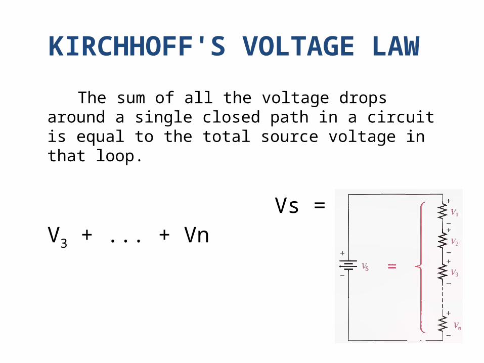
KIRCHHOFF'S VOLTAGE LAW
The sum of all the voltage drops around a single closed path in a circuit is equal to the total source voltage in that loop.
Vs = V1 + V2 + V3 + ... + Vn
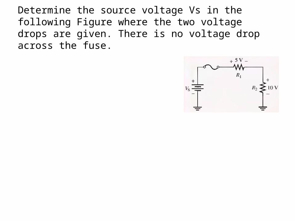
Determine the source voltage Vs in the following Figure where the two voltage drops are given. There is no voltage drop across the fuse.

Determine the unknown voltage drop, V3 , in the given Figure.
17V

Find the value of R4 in the following Figure.
2.0V , 9.4 V , 20 V , 68.6 V , =343 Ω
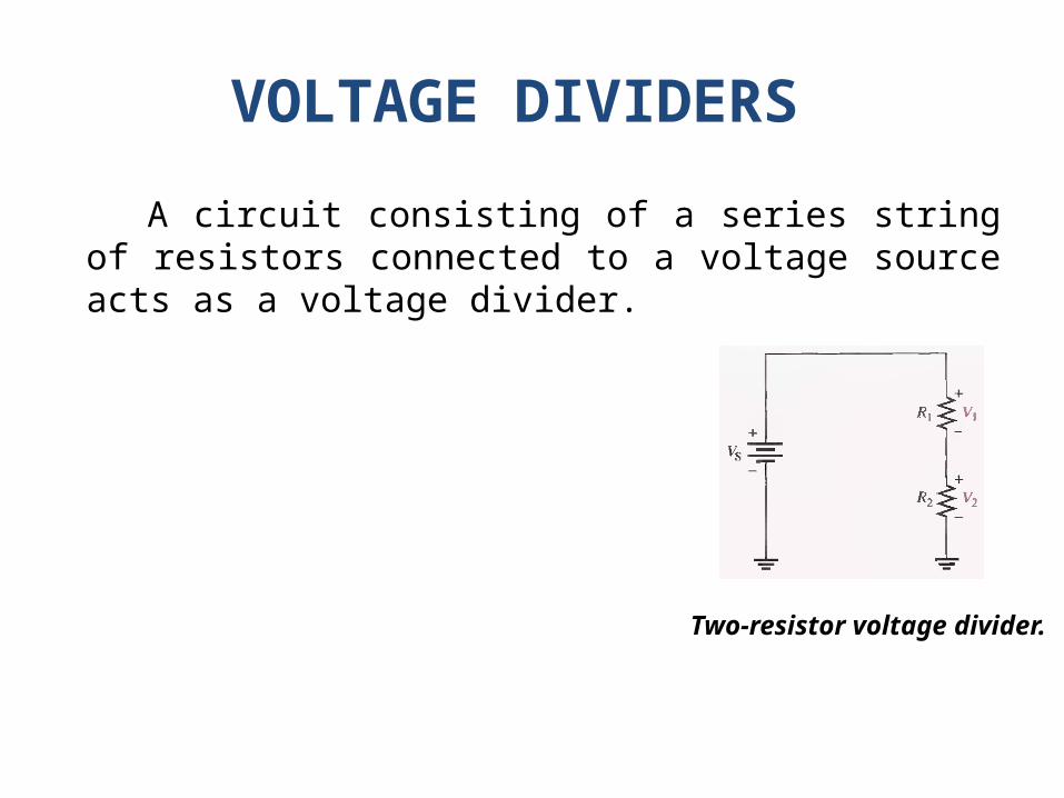
VOLTAGE DIVIDERS
A circuit consisting of a series string of resistors connected to a voltage source acts as a voltage divider.
Two-resistor voltage divider.

Voltage-Divider Formula
The voltage drop across any resistor or combination of resistors in a series circuit is equal to the ratio of that resistance value to the total resistance, multiplied by the source voltage.

Determine V1 (the voltage across R1 ) and V2 (the voltage across R2 ) in the voltage divider in following Figure.
156Ω, 6.41 V , 3.59 V

Calculate the voltage drop across each resistor in the voltage divider of following Figure.
1000Ω, 1V, 2.2V, 6.8V

Determine the voltages between the following points in the voltage divider of following Figure:
(a) A to B (b) A to C (c) B to C (d) B to D (e) C to D
12.5kΩ, 2V, 18.4 V 16.4 V, 23 V , 6.6 V


Summary
• Resistors in Series • Current in a Series Circuit • Total Series Resistance • Application of Ohm's Law • Voltage Sources in Series • Kirchhoff's Voltage Law • Voltage Dividers


