Ohm’s Law / Energy and Power / Electric Meters · A student uses a voltmeter to measure the...
36
12.4 Ohm’s Law / Energy and Power / Electric Meters
Transcript of Ohm’s Law / Energy and Power / Electric Meters · A student uses a voltmeter to measure the...

12.4
Ohm’s Law / Energy and Power / Electric Meters
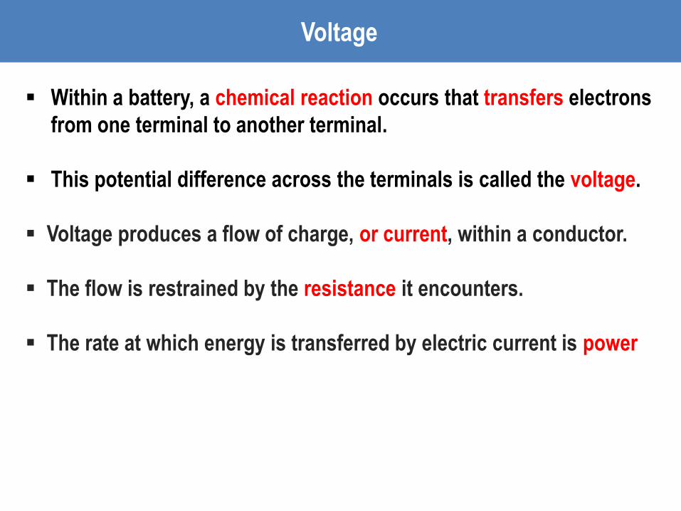
Within a battery, a chemical reaction occurs that transfers electrons
from one terminal to another terminal.
This potential difference across the terminals is called the voltage.
Voltage produces a flow of charge, or current, within a conductor.
The flow is restrained by the resistance it encounters.
The rate at which energy is transferred by electric current is power
Voltage
Ohm’s Law
The relationship among voltage, current, and resistance is called
Ohm’s Law.
Ohm’s Law states:
Current in a circuit is directly proportional to the voltage across
the circuit, and is inversely proportional to the resistance of the circuit.

Voltage
(Volts)
Current
(Amps)
Resistance
(Ohms Ω)
Ohm’s Law Formula
Example #1
An iron supplies 6 amps of current and has 20 Ω of resistance.
What is the voltage?
120 V
Ohm’s Law

Example #1
The current in a wire is 24 amperes when connected to a 1.5
volt battery. Find the resistance of the wire.
0.0625 Ω
Ohm’s Law
Example #2
In a simple electric circuit, a 24 Ω resistor is connected across a
6 volt battery. What is the current in the circuit?
0.25 A
Ohm’s Law

Electric Circuits

• In an electric circuit, an energy source and an energy
consuming device are connected by conducting wires through
which electric charges move.
Electric Circuits
• Electric Circuits are typically represented using diagrams know as schematics.
• Schematics are simplified, standard representation in which common circuit elements are represented with specific symbols, and wires connecting the elements in the circuits are represented by lines.
Electric Circuits

Electric Circuits

V = 12 V R = 6 Ω
I = 2 A
V = 12 V R = 3 Ω
I = 4 A
Ohm’s Law with Schematics
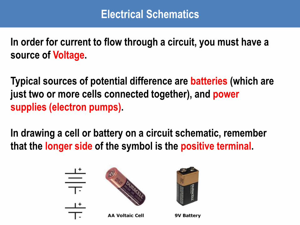
In order for current to flow through a circuit, you must have a
source of Voltage.
Typical sources of potential difference are batteries (which are
just two or more cells connected together), and power
supplies (electron pumps).
In drawing a cell or battery on a circuit schematic, remember
that the longer side of the symbol is the positive terminal.
Electrical Schematics

Voltage

Electric circuits must form a complete conducting path
(closed loop) in order for current to flow.
In the example circuit shown below, the circuit is incomplete
because the switch is open, therefore no current will flow
and the lamp will not light.
Electrical Schematics

In the circuit below, the switch is closed, creating a closed
loop path. Current will flow and the lamp will light up.
Electrical Schematics

Just like mechanical power is the rate at which mechanical
energy is expended, electrical power is the rate at which
electrical energy is expended.
Formula(s):
VIP RIP 2
R
VP
2
SI Unit of Power: Watts (W)
Energy and Power
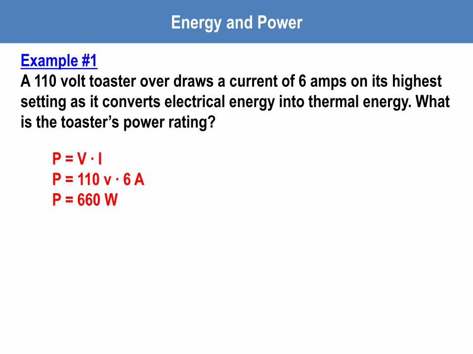
Example #1
A 110 volt toaster over draws a current of 6 amps on its highest
setting as it converts electrical energy into thermal energy. What
is the toaster’s power rating?
P = V ∙ I
P = 110 v ∙ 6 A
P = 660 W
Energy and Power

Example #2
A potential drop of 50 volts is measured across a 250 Ω resistor.
What is the power in the resistor?
Energy and Power
P = V2 / R
P = (50 V)2 / 250 Ω
P = 10 W

Example #3
Complete the table
20 W
0.5 W
15 V
6 V
20 Ω
132.25 Ω
Energy and Power
Series and Parallel Connections
Electrical Meters

The basic idea of a “series” connection is that components are
connected end-to-end in a line to form a single path for electrons to flow.
Series Connections
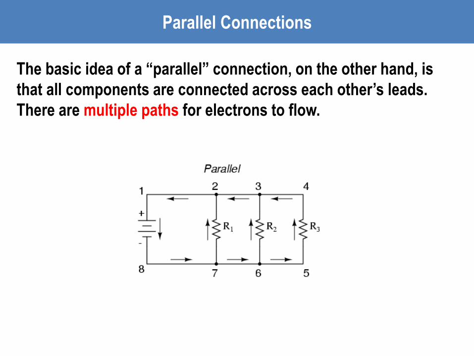
The basic idea of a “parallel” connection, on the other hand, is
that all components are connected across each other’s leads.
There are multiple paths for electrons to flow.
Parallel Connections

Meters
Electrical Meters

Voltmeters are tools used to measure the voltage between
two points in a circuit.
The voltmeter is connected in parallel with the element to
be measured, meaning an alternate current path around the
element to be measured and through the voltmeter is
created.
Electrical Meters - Voltmeters
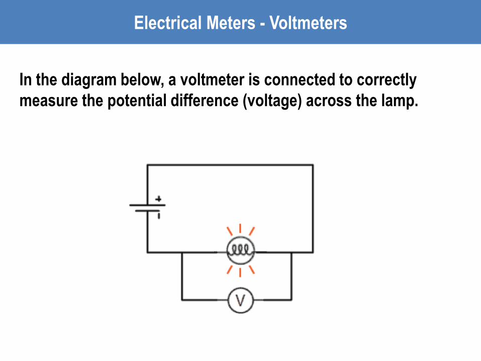
In the diagram below, a voltmeter is connected to correctly
measure the potential difference (voltage) across the lamp.
Electrical Meters - Voltmeters
Ammeters are tools used to measure the current in a circuit.
The ammeter is connected in series with the circuit, so that
the current to be measured flows directly through the
ammeter.
Electrical Meters - Ammeters

In the diagram below, a ammeter is connected to correctly
measure the current flowing through the circuit.
Electrical Meters - Ammeters

Electrical Meters

Electrical Meters - Voltage
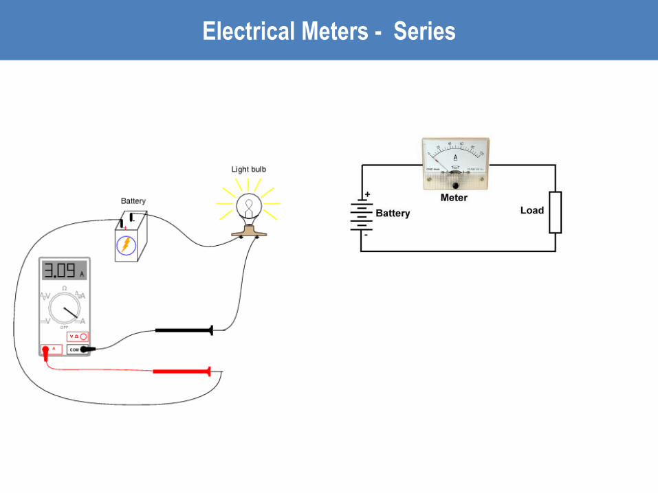
Electrical Meters - Series

Electrical Meters

Electrical Meters

Example #1
In the electric circuit diagram, possible locations of an ammeter
and voltmeter are indicated by circles 1, 2, 3, and 4. Where should
the ammeter be located and where should a voltmeter be located
to correctly measure the total current and voltage?
Ammeter: 1
Voltmeter: 4
Electrical Meters
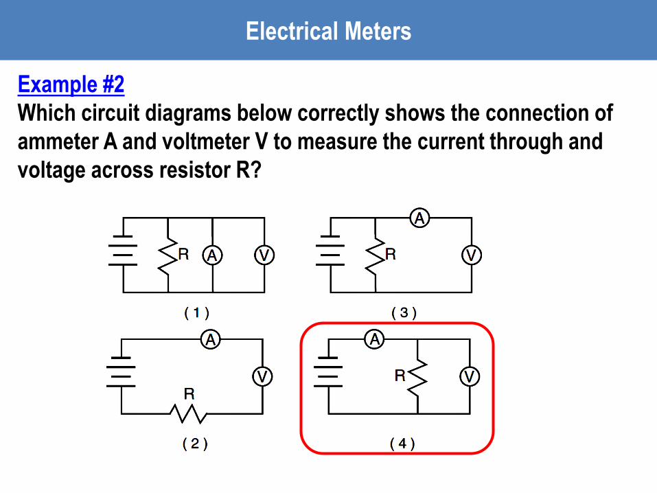
Example #2
Which circuit diagrams below correctly shows the connection of
ammeter A and voltmeter V to measure the current through and
voltage across resistor R?
Electrical Meters

Example #3
A student uses a voltmeter to measure the voltage across a
resistor. To obtain a correct reading, the student must connect
the voltmeter:
a. In series with the resistor
b. In parallel with the resistor
c. Before connecting the other circuit components
d. After connecting the other circuit components
Electrical Meters