Preventive Maintenance LX Project XX · Web viewVisual inspection of wiring to and from the unit X...
53
Ó Copyright 2017 ABB. All rights reserved. Preventive Maintenance LX Project XX ABB AB Title: Preventive Maintenance LX Project XX Doc No.: Doc. Kind: Lang.: en Project name: Revision: Creator name: Pia Sandberg Status: Draft Department code: MSO Date: 2017-08-10 E-mail: [email protected] Page: 1/53 Time period:
Transcript of Preventive Maintenance LX Project XX · Web viewVisual inspection of wiring to and from the unit X...

Preventive Maintenance LX Project XX
ÓC
opyr
ight
201
7 A
BB
. All
right
s re
serv
ed.
ABB AB Title: Preventive Maintenance LX Project XX
Doc No.: Doc. Kind:
Lang.: en Project name:
Revision: Creator name: Pia Sandberg
Status: Draft Department code: MSO
Date: 2017-08-10 E-mail: [email protected]
Page: 1/39 Time period:

ÓC
opyr
ight
201
7 A
BB
. All
right
s re
serv
ed.
Table of Contents1. General data 3
1.1. Customer reference 31.2. Machine details 31.3. Driven equipment details 31.4. Site condition and operating data 32. ABB preventive maintenance program – Basic concept 43. Summary 5
3.1. Summary of work done 53.2. Recommendations 53.3. Discovered irregularities and action taken 63.4. Spare parts 74. Preventive maintenance program 8
4.1. Machine 84.2. Stator 94.3. Stator terminal 104.4. Rotor 114.5 Bearings 124.6 Run down tank 134.7 Exciter and Rectifier 144.8. Start resistor 154.9 Permanent Magnet Generator (PMG) 164.10 Rotor earth fault brush 174.11 Rotor earth brush 184.12 Cooling system 194.13 Cooling fan motor and fan 205. Protocols 21
Protocol: Logged data 21Protocol: Insulation resistance/Polarization Index (PI) 22Protocol: Insulation resistance/Polarization Index (PI) 23Protocol: Resistance of RTD’s (PT100) 24Protocol: Resistance of RTD’s (PT100) cont. 25Protocol: Resistance of RTD’s (PT100) 26Protocol: Resistance of RTD’s (PT100) cont. 27Protocol: Resistance and Insulation resistance of heaters 28Protocol: Insulation resistance of rotor 29Protocol: Main rotor impedance 4 pole 30Protocol: Main rotor impedance 6 pole 31Protocol: Coil support insulation plates 32Protocol: Coil support insulation plates 6 pole 33Protocol: Air gap and clearance 34Protocol: Insulation resistance of exciter PMG stator and firing level of CPU 35Protocol: Insulation resistance of start resistor 36Protocol: Leakage test coolers 376. Additional site and machine information 387. Appendix 38
Title: Preventive Maintenance LX Project XX
Dep: DM/DMMG/MS/MST
Doc No.:
Date: 2015-06-16
Page: 2/39

1. General data
1.1. Customer reference
Name Company Phone number e-mail address
1.2. Machine details Machine type Serial number Work order number Original order number AC/DC Power (kW) Voltage (V) Frequency (Hz) Full load current (A) Speed (RPM) Poles Insulation Class Temperature rise class Degree of protection Duty Power factor Efficiency (%) Motor driven by VSD Year of manufacture Weight
Protection type Ex II T Ex certificate number Ex ref. standards
1.3. Driven equipment detailsEquipment type
1.4. Site condition and operating dataMotor’ protection devices Foundation type Machine mounting Coupling type
Operating hours No. of starts Equivalent operating hours
Title: Preventive Maintenance LX Project XX
Dep: MSO
Doc No.:
Date: 2017-08-10
Page: 3/39

2. ABB preventive maintenance program – Basic conceptThis is an overview of the preventive maintenance program. A maintenance schedule is determined from actual site conditions, number of operating hours, the mode of operation and the number of starts of the Motor/Generator. Enclosed report is information from the inspection. All cross-sections of machine parts are principal sketches and not necessary for the actual machine.
Level 1(L1)
Level 2(L2)
Level 3(L3)
Level 4(L4)
Interval Max. 10 000h (equivalent hours) of operation or yearly
Max. 20 000h (equivalent hours) of operation or max. 3 years
Max 40 000h (equivalent hours) of operation or max. 6 years
Max 80 000h (equivalent hours) of operation or max. 12 years
Preparation for inspection
Opening of inspection covers
Opening of inspection covers
Disassembly of covers. Opening of bearings. Opening of water coolers (if coolers)
Opening of bearings. Removal of rotor and exciter. Opening of water coolers (if coolers)
Maintenance parts
L1 Preventive Maintenance Kit
L2 Preventive Maintenance Kit and recommendations from earlier inspections
L3 Preventive Maintenance Kit and recommendations from earlier inspections
L4 Preventive Maintenance Kit and recommendations from earlier inspections
Exp. downtime Approx. 1 day Approx. 2 days Approx. 5 days Approx. 10 days
Equivalent hours = Total hours of operation + number of starts x 20
Example of maintenance scheduleInterval[approx.
1 2 3 4 5 6 7 8 9 …
Interval[hours x 10 20 30 40 50 60 70 80 90 …
Level L1 L2 L1 L3 L1 L2 L1 L4 L1 …
The table above is for information only. Consult your ABB motor/generator specialist for specific recommendations.
Electrical measurements are performed according to ABB AB Machines Technical Provisions.
3BSM005426 Measurement of impedance on rotor complete4104016E-3 Insulation resistance
4104016E-4 Polarization Index
Title: Preventive Maintenance LX Project XX
Dep: MSO
Doc No.:
Date: 2017-08-10
Page: 4/39

3. Summary 3.1. Summary of work doneThis section includes a summary of the main performed actions / surveys / findings.Details are described in the next dedicated sessions/pages.
3.2. RecommendationsThis section includes recommendations for future operation and maintenance.
Title: Preventive Maintenance LX Project XX
Dep: MSO
Doc No.:
Date: 2017-08-10
Page: 5/39

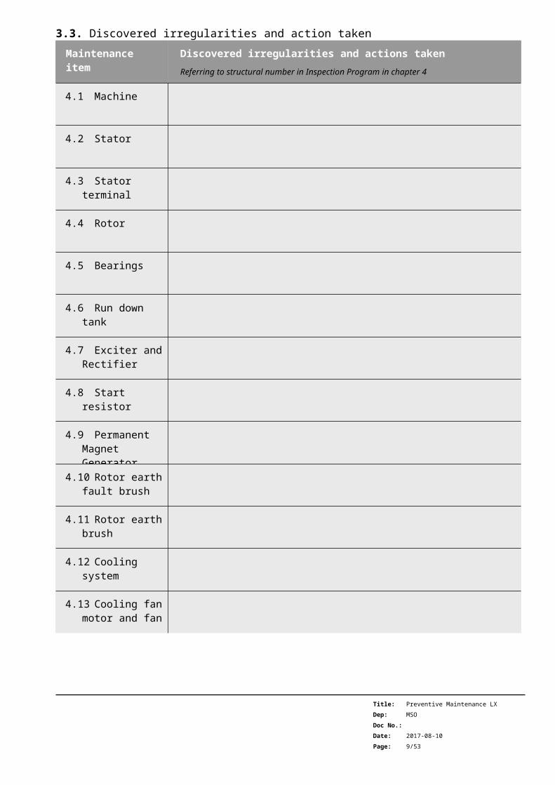
3.3. Discovered irregularities and action takenMaintenance item Discovered irregularities and actions taken
Referring to structural number in Inspection Program in chapter 4
4.1 Machine
4.2 Stator
4.3 Stator terminal
4.4 Rotor
4.5 Bearings
4.6 Run down tank
4.7 Exciter and Rectifier
4.8 Start resistor
4.9 Permanent Magnet Generator (PMG)
4.10 Rotor earth fault brush
4.11 Rotor earth brush
4.12 Cooling system
4.13 Cooling fan motor and fan
Title: Preventive Maintenance LX Project XX
Dep: MSO
Doc No.:
Date: 2017-08-10
Page: 6/39

3.4. Spare partsMaintenance item
1. Materials and spare parts used
2. Recommended spare parts
Title: Preventive Maintenance LX Project XX
Dep: MSO
Doc No.:
Date: 2017-08-10
Page: 7/39

4. Preventive maintenance program4.1. MachineA=Approved / B=Approved with remarks / C=Not approved / D=Approved after action taken / NA=Not applicable
Location L3 L4 Activity A B C D NA
1. Machine X X 1. Look through all logged or recorded data available; load, temperature, vibrations etc.Protocol: Logged data
X X 2. Visual inspection of exterior of machine for rust, leaks or other defects
X X 3. Visual inspection of all external fastenings
X X 4. Visual inspection of ventilation ducts2. Foundation
X X 1. Visual inspection of grouting and anchored bolts. Check for excessive clearances and correct as required. Inspect for cracks in the foundation.
3. Service and repair X X 1. Replacing, cleaning and modification acc.
to recommendation in earlier inspections and suppliers service bulletin
4. Purging X X 1. Check for leaks after assembling
5. Others X X 1. Visual inspection
Title: Preventive Maintenance LX Project XX
Dep: MSO
Doc No.:
Date: 2017-08-10
Page: 8/39
4.2. StatorA=Approved / B=Approved with remarks / C=Not approved / D=Approved after action taken / NA=Not applicable
Location L3 L4 Activity A B C D NA
1. Stator winding
X X 1. Visual inspection of winding connections
X X 2. Visual inspection of winding and bracing rope
X X 3. Visual inspection of cleanliness, discoloration, condition of insulation, looseness, movement and wear
X X 4. Measure and record insulation resistanceProtocol: Insulation resistance/Polarization Index (PI)
X X 5. Measure Polarization IndexProtocol: Insulation resistance/Polarization Index (PI)
2. Air cover X X 1. Visual inspection of sealing
3. RTDs X X 1. Verify function of all RTDsProtocol: Resistance of RTD’s (PT100)
4. Stand still heaters
X X 1. Function checkProtocol: Resistance and Insulation resistance of heaters
5. Stator core X 1. Visual inspection.
6. Others X X 1. Visual inspection
Title: Preventive Maintenance LX Project XX
Dep: MSO
Doc No.:
Date: 2017-08-10
Page: 9/39

4.3. Stator terminalA=Approved / B=Approved with remarks / C=Not approved / D=Approved after action taken / NA=Not applicable
Location L3 L4 Activity A B C D NA
1. Terminal box
X X 1. Visual inspection of all line – and neutral connections and stator bushings
X X 2. Visual inspection of general condition
X X 3. Check tightening torque at all connections and insulation behind the terminals
X X 4. Inspection of pressure relief hatch
X X 5. Visual inspection of insulators
2. Others X X 1. Visual inspection
Title: Preventive Maintenance LX Project XX
Dep: MSO
Doc No.:
Date: 2017-08-10
Page: 10/39

4.4. RotorA=Approved / B=Approved with remarks / C=Not approved / D=Approved after action taken / NA=Not applicable
Location L3 L4 Activity A B C D NA1. Rotor X X 1. Visual inspection of all brazed connections for
cracks and discoloration
X X 2. Measure and record insulation resistance. Protocol: Insulation resistance of rotor
2. Rotor coils X X 1. Visual inspection of turn to turn insulation, discoloration etc.
X X 2. Visual inspection interconnections
X X 3. Measure turn to turn insulation (impedance)Protocol: Main rotor impedance
3. Rotor coil support
X X 1. Visual inspection of coil supports, screws, washers and insulation
X X 2. Check upper coil support insulation plate for movementProtocol: Control of coil support insulation plates
4. Pole shoes X X 1. Visual inspection of pole shoes for discoloration
5. Pole bolts X 1. Inspection of bolt heads
6. Fan X X 1. Visual inspection of fan blades and welding
7. Balancing X X 1. Visual inspection balancing weights and fastening and details
8. Air gap X 1. Check air gap after assembling of machineProtocol: Air gap and clearance
9. Others X X 1. Visual inspection
Title: Preventive Maintenance LX Project XX
Dep: MSO
Doc No.:
Date: 2017-08-10
Page: 11/39

4.5 Bearings A=Approved / B=Approved with remarks / C=Not approved / D=Approved after action taken / NA=Not applicable
Location L3 L4 Activity A B C D NA
1. Bearing X X 1. Open bearings
2. Bearing housing and support
X X 1. Visual inspection for leaks
X X 2. Visual inspection of all bolted joints
X X 3. Visual inspection of guide support
3. Shaft seals X X 1. Visual inspection for leaks. If leaks are found, check for wear and damages
X X 2. Visual inspection of drain holes in the shaft seals
X X 3. Check clearance shaft seals/rotor shaftProtocol: Air gap and clearance
4. Shaft and bearing surface
X X 1. Visual inspection of the sealing surface regarding corrosion and wearing
X X 2. Visual inspection of bearing journal
5. Bearing liners
X X 1. Visual inspection of contact surfaces
6. Bearing insulation
X1) X 1. Measure insulation resistanceProtocol: Air gap and clearance
7. Oil piping X X 1. Visual inspection for leaks
8. Measuring instrument
X X 1. Visual inspection of all measuring instruments
9. Lube oil X X 1. Visual inspection of oil quality
10. Air filter X X 1. Visual inspection of air filters for dirt and clogging
11. Air lock hoses
X X 1. Visual inspection of hoses for air lock hoses
12. Others X X 1. Visual inspection
X1) can be performed if rotor coupling is disconnected
Title: Preventive Maintenance LX Project XX
Dep: MSO
Doc No.:
Date: 2017-08-10
Page: 12/39

4.6 Run down tank A=Approved / B=Approved with remarks / C=Not approved / D=Approved after action taken / NA=Not applicable
Location L3 L4 Activity A B C D NA
1. Air filter X X 1. Visual inspection of air filters for dirt and clogging
2. Tank X X 1. Inspect exterior of machine for rust, leaks and other defects
X X 2. Verify function of level indicator
3. Hoses X X 1. Visual inspection of hydraulic hoses for leaks or other defects
4. Others X X 1. Visual inspection
Title: Preventive Maintenance LX Project XX
Dep: MSO
Doc No.:
Date: 2017-08-10
Page: 13/39

4.7 Exciter and Rectifier A=Approved / B=Approved with remarks / C=Not approved / D=Approved after action taken / NA=Not applicable
Location L3 L4 Activity A B C D NA
1. Exciter Rotor
X X 1. Visual inspection
X X 2. Measure and record insulation resistanceProtocol: Insulation resistance of exciter PMG stator and firing level of CPU
X X Function test of diode, thyristor and CPU circuitProtocol: Insulation resistance of exciter PMG stator and firing level of CPU
2. Diodes, thyristors
X X 1. Visual inspection of cleanliness
X X 2. Check all bolts fastening
X X 3. Replacing of diodes and thyristors
3. Control pulse unit
X X 1. Visual inspection of wiring to and from the unit
X X 2. Visual inspection of firing level setting
X X 3. Replacing of Control Pulse unit
4. Rotor terminal
X X 1. Visual inspection of all connections to the exciter
5. Exciter stator
X X 1. Visual inspection
X X 2. Measure and record insulation resistanceProtocol: Insulation resistance of exciter PMG stator and firing level of CPU
6. Air gap X X 1. Check air gapProtocol: Air gap and clearance
7. Stand still heaters
X X 1. Function checkProtocol: Resistance and Insulation resistance of heaters
8. Others X X 1. Visual inspection
Title: Preventive Maintenance LX Project XX
Dep: MSO
Doc No.:
Date: 2017-08-10
Page: 14/39

4.8. Start resistorA=Approved / B=Approved with remarks / C=Not approved / D=Approved after action taken / NA=Not applicable
Location L3 L4 Activity A B C D NA
1. Start resistor
X X 1. Visual inspection of the start resistor
X X 2. Measure insulation resistance, 500 V DC meggerProtocol: Insulation resistance of start resistor
X X 3. Inspection for cleanliness, discoloration, condition of insulation, looseness, movement and wear. Clean if necessary.
2. Thyristors X X 1. General cleaning.
X X 2. Check all bolts fastening.
3. Resistor Control Pulse Unit (RCPU)
X X 1. Check wiring to and from the unit.
X X 2. Visual inspection of resistor control pulse unit.
4. Rotor terminals
X X 1. Check all connections between the start resistor and the exciter.
Title: Preventive Maintenance LX Project XX
Dep: MSO
Doc No.:
Date: 2017-08-10
Page: 15/39

4.9 Permanent Magnet Generator (PMG) A=Approved / B=Approved with remarks / C=Not approved / D=Approved after action taken / NA=Not applicable
Location L3 L4 Activity A B C D NA
1. PMG Stator X X 1. Visual inspection
X X 2. Measure and record insulation resistanceProtocol: Insulation resistance of exciter PMG stator and firing level of CPU
2. PMG Rotor X X 1. Visual inspection
3. Air gap X X 1. Check air gapProtocol: Air gap and clearance
4. Others X X 1. Visual inspection
Title: Preventive Maintenance LX Project XX
Dep: MSO
Doc No.:
Date: 2017-08-10
Page: 16/39

4.10 Rotor earth fault brushA=Approved / B=Approved with remarks / C=Not approved / D=Approved after action taken / NA=Not applicable
Location L3 L4 Activity A B C D NA
1. Brush and brush holder
X X 1. Visual inspection and check of brush. Replace if shorter than 15 mm
X X 2. Measure and record insulation resistanceProtocol: Insulation resistance of rotor
X X 3. Check and clean brush holder
X X 4. Check rotor ground fault protection alarm
2. Slip ring X X 1. Visual inspection of slip ring
3. Others X X 1. Visual inspection
Title: Preventive Maintenance LX Project XX
Dep: MSO
Doc No.:
Date: 2017-08-10
Page: 17/39

4.11 Rotor earth brush A=Approved / B=Approved with remarks / C=Not approved / D=Approved after action taken / NA=Not applicable
Location L3 L4 Activity A B C D NA
1. Brush and brush holder
X X 1. Visual inspection and check of brushes. Replace if shorter than 15 mm
X X 2. Check and clean brush holder
2. Others X X 1. Visual inspection
Title: Preventive Maintenance LX Project XX
Dep: MSO
Doc No.:
Date: 2017-08-10
Page: 18/39

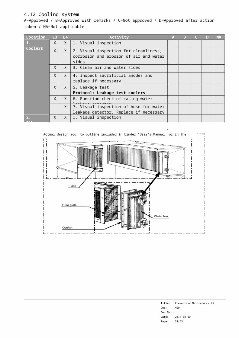
4.12 Cooling systemA=Approved / B=Approved with remarks / C=Not approved / D=Approved after action taken / NA=Not applicable
Location L3 L4 Activity A B C D NA1. Coolers X X 1. Visual inspection
X X 2. Visual inspection for cleanliness, corrosion and erosion of air and water sides
X X 3. Clean air and water sides
X X 4. Inspect sacrificial anodes and replace if necessary
X X 5. Leakage testProtocol: Leakage test coolers
X X 6. Function check of casing water leakage detector
X 7. Visual inspection of hose for water leakage detector. Replace if necessary
2. Others X X 1. Visual inspection
Title: Preventive Maintenance LX Project XX
Dep: MSO
Doc No.:
Date: 2017-08-10
Page: 19/39
Actual design acc. to outline included in binder “User’s Manual” or in the introduction of this document.

4.13 Cooling fan motor and fanA=Approved / B=Approved with remarks / C=Not approved / D=Approved after action taken / NA=Not applicable
Location L3 L4 Activity A B C D NA
1. Cooling fan motor
X X 1. Visual inspection
X X 2. Visual inspection of the exterior of fan motor and fan wheel
X X 3. Run the fan motor and fan during standstill to check the condition, e.g. vibration, noise, bearing, etc.
Title: Preventive Maintenance LX Project XX
Dep: MSO
Doc No.:
Date: 2017-08-10
Page: 20/39

5. ProtocolsProtocol: Logged data
Data before shut down
Power MW/MVA
Power factor Cos
Stator current kA
Excitation current ABearing temperature, D-end CBearing temperature, ND-end CWinding temperature, U CWinding temperature, V CWinding temperature, W CCold air, CCold water C (if water cooler)Warm air, CVibration level, D-end Y m
X m
Vibration level, ND-end Y m
X m
Operation hours hNumber of start noLube oil flow Litre/minLube oil pressure barg
Date:
Checked by:
Title: Preventive Maintenance LX Project XX
Dep: MSO
Doc No.:
Date: 2017-08-10
Page: 21/39

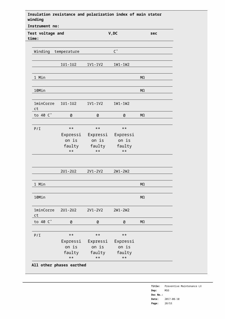
Protocol: Insulation resistance/Polarization Index (PI)
Insulation resistance and polarization index of main stator winding
Instrument no:
Test voltage and time: V,DC sec
Winding temperature C˚
1U1-1U2 1V1-1V2 1W1-1W2
1 Min MΩ
10Min MΩ
1minCorrect 1U1-1U2 1V1-1V2 1W1-1W2to 40 C˚ 0 0 0 MΩ
P/I **Expressionis faulty **
**Expressionis faulty **
**Expressionis faulty **
2U1-2U2 2V1-2V2 2W1-2W2
1 Min MΩ
10Min MΩ
1minCorrect 2U1-2U2 2V1-2V2 2W1-2W2to 40 C˚ 0 0 0 MΩ
P/I **Expressionis faulty **
**Expressionis faulty **
**Expressionis faulty **
All other phases earthed
Date:
Checked by:
Title: Preventive Maintenance LX Project XX
Dep: MSO
Doc No.:
Date: 2017-08-10
Page: 22/39

Protocol: Insulation resistance/Polarization Index (PI)
Insulation resistance and polarization index of main stator winding.
Instrument no:
Test voltage and time: V,DC sec
Winding temperature C˚
U V W
1 Min MΩ
10Min MΩ
1minCorrect U V Wto 40 C˚ 0 0 0 MΩ
P/I **Expressionis faulty **
**Expressionis faulty **
**Expressionis faulty **
All other phases earthed
Date:
Checked by:
Title: Preventive Maintenance LX Project XX
Dep: MSO
Doc No.:
Date: 2017-08-10
Page: 23/39
Protocol: Resistance of RTD’s (PT100)
Resistance measured with a digital multi meterInstrument no:
Measured CalculatedResistance Temp.
Located Terminal no. C
Stator winding phase 1 501-502 Stator winding phase 1 502-503 -254Stator winding phase 2 504-505 Stator winding phase 2 505-506 -254Stator winding phase 3 507-508 Stator winding phase 3 508-509 -254Stator winding phase 1 511-512 Stator winding phase 1 512-513 -254Stator winding phase 2 514-515 Stator winding phase 2 515-516 -254Stator winding phase 3 517-518 Stator winding phase 3 518-519 -254 -254In warm air 551-552 In warm air 552-553 -254In warm air 554-555 In warm air 555-556 -254In cold air NDE 557-558 In cold air NDE 558-559 -254In cold air NDE 560-561 In cold air NDE 561-562 -254In cold air DE 563-564 In cold air DE 564-565 -254In cold air DE 566-567 In cold air DE 567-568 -254Date:
Checked by:
Title: Preventive Maintenance LX Project XX
Dep: MSO
Doc No.:
Date: 2017-08-10
Page: 24/39

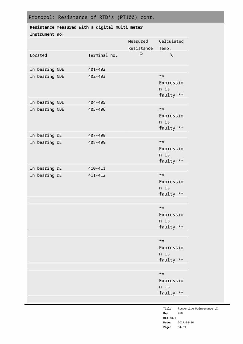
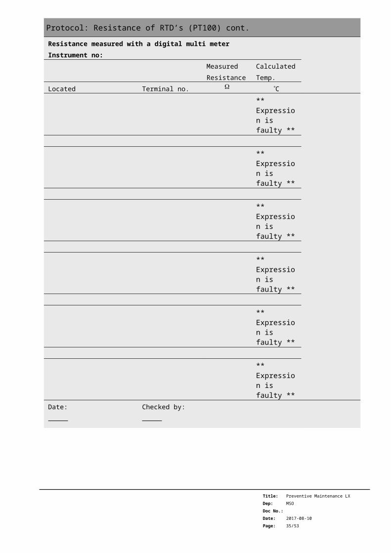
Protocol: Resistance of RTD’s (PT100) cont.
Resistance measured with a digital multi meterInstrument no:
Measured CalculatedResistance Temp.
Located Terminal no. C
In bearing NDE 401-402 In bearing NDE 402-403 -254In bearing NDE 404-405 In bearing NDE 405-406 -254In bearing DE 407-408 In bearing DE 408-409 -254In bearing DE 410-411 In bearing DE 411-412 -254 -254 -254 -254 -254 -254 -254 -254 -254 -254Date:
Checked by:
Title: Preventive Maintenance LX Project XX
Dep: MSO
Doc No.:
Date: 2017-08-10
Page: 25/39

Protocol: Resistance of RTD’s (PT100)
Resistance measured with a digital multi meterInstrument no:
Measured CalculatedResistance Temp.
Located Terminal no. C
Stator winding phase U 501-504 Stator winding phase U 501-502 -254Stator winding phase U 502-503 Stator winding phase V 505-508 Stator winding phase V 505-506 -254Stator winding phase V 506-507 Stator winding phase W 509-512 Stator winding phase W 509-510 -254Stator winding phase W 510-511 Stator winding phase U 513-516 Stator winding phase U 513-514 -254Stator winding phase U 514-515 Stator winding phase V 517-520 Stator winding phase V 517-518 -254Stator winding phase V 518-519 Stator winding phase W 521-524 Stator winding phase W 521-522 -254Stator winding phase W 522-523 -254 -254 Date:
Checked by:
Title: Preventive Maintenance LX Project XX
Dep: MSO
Doc No.:
Date: 2017-08-10
Page: 26/39

Protocol: Resistance of RTD’s (PT100) cont.
Resistance measured with a digital multi meterInstrument no:
Measured CalculatedResistance Temp.
Located Terminal no. C
In warm air 551-554 In warm air 551-552 -254In warm air 552-553 In cold air NDE 555-558 In cold air NDE 555-556 -254In cold air NDE 556-557 In cold air DE 559-562 In cold air DE 559-560 -254In cold air DE 560-561 In warm air exciter 563-566 In warm air exciter 563-564 -254In warm air exciter 564-565 In bearing NDE 401-404 In bearing NDE 401-402 -254In bearing NDE 402-403 In bearing DE 405-408 In bearing DE 405-406 -254In bearing DE 406-407 -254 -254 Date:
Checked by:
Title: Preventive Maintenance LX Project XX
Dep: MSO
Doc No.:
Date: 2017-08-10
Page: 27/39
Protocol: Resistance and Insulation resistance of heaters
Resistance measured with a digital multi meterInstrument no: Heaters in stator marked: W VHeaters in exciter marked: W VAmbient temperature: C
Located Terminal Resistanceno.
Terminal box Stator Stator Stator Exciter
Insulation resistance Instrument no: Test voltage and time: V,DC SECAmbient temperature: C
Terminal 1 min Controlno. M of function
Terminal box Stator Stator Stator Exciter
Date:
Checked by:
Title: Preventive Maintenance LX Project XX
Dep: MSO
Doc No.:
Date: 2017-08-10
Page: 28/39

Protocol: Insulation resistance of rotor
Instrument no:
Test voltage and time: V,DC sec
Insulation resistance complete field circuit
Winding temperature: C
1 minute value MΩ
Corrected value to 40˚C 0 MΩ
Insulation resistance main rotor disconnected from exciter rotor
Winding temperature: C
1 minute value MΩ
Corrected value to 40˚C 0 MΩ
Insulation resistance exciter rotor disconnected from rotating rectifier
Winding temperature: C
1 minute value MΩCorrected value to 40˚C 0 MΩ
Insulation resistance rotating rectifierWinding temperature: C1 minute value MΩ
Corrected value to 40˚C 0 MΩ
Insulation resistance of bearing insulation1 minute value MΩ
Insulation resistance of brush holder1 minute value MΩ
Date:
Checked by:
Title: Preventive Maintenance LX Project XX
Dep: MSO
Doc No.:
Date: 2017-08-10
Page: 29/39

Protocol: Main rotor impedance 4 pole
Instrument no:
Voltage Amps Ohm Hz
Pole 1 ** Expression is faulty **
** Expression is faulty **
Pole2 ** Expression is faulty **
** Expression is faulty **
Pole3 ** Expression is faulty **
** Expression is faulty **
Pole4 ** Expression is faulty **
** Expression is faulty **
Total 0
Tot Ω/4 ** Expression is faulty **
Date:
Checked by:
Title: Preventive Maintenance LX Project XX
Dep: MSO
Doc No.:
Date: 2017-08-10
Page: 30/39

Protocol: Main rotor impedance 6 pole
Instrument no:
Voltage Amps Ohm Hz
Pole 1 ** Expression is faulty **
** Expression is faulty **
Pole2 ** Expression is faulty **
** Expression is faulty **
Pole3 ** Expression is faulty **
** Expression is faulty **
Pole4 ** Expression is faulty **
** Expression is faulty **
Pole5 ** Expression is faulty **
** Expression is faulty **
Pole6 ** Expression is faulty **
** Expression is faulty **
Total 0 Tot Ω/6 ** Expression is faulty **
Date:
Checked by:
Title: Preventive Maintenance LX Project XX
Dep: MSO
Doc No.:
Date: 2017-08-10
Page: 31/39

Protocol: Coil support insulation plates
Movement of insulation plates before replacement
Direction of rotations
Date:
Checked by:
Title: Preventive Maintenance LX Project XX
Dep: MSO
Doc No.:
Date: 2017-08-10
Page: 32/39
Movement [mm]
A B C D E
Position Left Right Left Right Left Right Left Right Left Right
1-2
2-3
3-4
4-1

Protocol: Coil support insulation plates 6 pole
Movement of insulation plates before replacement
Direction of rotations
Date:
Checked by:
Title: Preventive Maintenance LX Project XX
Dep: MSO
Doc No.:
Date: 2017-08-10
Page: 33/39
Movement [mm]
A B C D E
Position Left Right Left Right Left Right Left Right Left Right
1-2
2-3
3-4
4-5
5-6
6-1
Protocol: Air gap and clearance
Z+
Y+ Y-
Z-
Measured values in mm according to picture above seen from driven end
Z+ Y- Z- Y+Air-gap measurement between main rotor and stator DEAir-gap measurement between main rotor and stator NDEAir-gap measurement between exciter rotor and stator Air-gap measurement between PMG rotor and stator
Clearance rotor shaft/bearing seals DE inClearance rotor shaft/bearing seals DE out
Clearance rotor shaft/bearing seals NDE inClearance rotor shaft/bearing seals NDE out
Clearance air lock seal DE
Clearance air lock seal NDE
Date:
Checked by:
Title: Preventive Maintenance LX Project XX
Dep: MSO
Doc No.:
Date: 2017-08-10
Page: 34/39
Protocol: Insulation resistance of exciter PMG stator and firing level of CPU
Instrument no: Test voltage and time: V,DC sec
Insulation resistance Exciter statorWinding temperature: C1 minute value MΩCorrected value to 40˚C 0 MΩ
Insulation resistance PMG Stator Winding temperature: C1 minute value MΩCorrected value to 40˚C 0 MΩ
Setting of CPU voltage
Existing CPU setting YT352011-A Volt
New CPU setting VoltFunction test of rectifier components
Circuit verified Approved Not approvedDate:
Checked by:
Title: Preventive Maintenance LX Project XX
Dep: MSO
Doc No.:
Date: 2017-08-10
Page: 35/39

Protocol: Insulation resistance of start resistor
Instrument no: Test voltage and time: V,DC sec
Insulation resistance start resistorWinding temperature: C1 minute value MΩCorrected value to 40˚C 0 MΩ
Date:
Checked by:
Title: Preventive Maintenance LX Project XX
Dep: MSO
Doc No.:
Date: 2017-08-10
Page: 36/39

Protocol: Leakage test coolers
The coolers have been leakage tested with:
Medium: For minutesPressure bar
Recommended test pressure is working pressure plus 10%.
Approved Approved after action
Not approved
Cooler No:
Cooler No:
Cooler No:
Cooler No:
Date:
Checked by:
Title: Preventive Maintenance LX Project XX
Dep: MSO
Doc No.:
Date: 2017-08-10
Page: 37/39

6. Additional site and machine information
7. Appendix
Title: Preventive Maintenance LX Project XX
Dep: MSO
Doc No.:
Date: 2017-08-10
Page: 38/39

Rev. Date(yyyy-mm-dd)
Prepared by Division/ Department
Description
A 2014-12-01 Olle Ö MSO New document
B 2015-06-29 Isabelle W MST New document
Title: Preventive Maintenance LX Project XX
Dep: MSO
Doc No.:
Date: 2017-08-10
Page: 39/39