Pressure-relief damPers drK bacK-draught damPers rsK · PDF filePressure-relief damPers drK...
2
INSTALLATION, OPERATION AND MAINTENANCE INSTRUCTIONS PRESSURE-RELIEF DAMPERS DRK BACK-DRAUGHT DAMPERS RSK PRODUCT DESIGNATION DRK-10…., RSK10…. TECHNICAL SPECIFICATIONS Max. size W x H: DRK: 2400 mm x 7900 mm RSK: 7900 mm x 7900 mm (subject to shipping) Max. slat length: 1200 mm Tripping pressure: DRK: acc. to order RSK: no specified tripping pressure Air flow direction: horizontal or vertical acc. to customer order Free cross section: >60 % ((more precise figures after calculation by manufacturer) ATEX DRK and RSK are only approved in specific designs and with appropriate identification for Zones 1, 2, 21 and 22 according to ATEX Directive 94/9/EC. If the fitter or operator changes the dampers in any way, the ATEX approval becomes null and void. It is important to ensure that the damper and additional equipment are installed in compliance with zoning requirements. In principle, avoid all damage caused by external influ- ences. Never lift dampers by the slats or the outer lin- kages. Dampers with a maximum weight of 50 kg can be lifted by the C-profile frame. With heavier dam- pers, use at least four points at the corner angles as suspension points. Do not use individual slats under any circumstances as footholds during installation. Report any damage, e.g. deformation of slats, dents, impacts or warping of the C-profile frame etc. imme- SHIPMENT INSTALLATION diately to the supplier or manufacturer. This may im- pair the proper functioning of the damper and at best cause dangerous circumstances to occur. ATEX: Under no circumstances may ATEX dampers be fitted after a fall or impact with visible or concealed damage These dampers can be fitted or removed to or from a wall or an air conditioning system, or integrated in a duct section. First make sure the air flow is in the pro- per direction as indicated by the red arrow on the damper housing. Mount the dampers warp-free, ten- sion-free, on a flat surface and without any angular errors in the damper frame. When mounting, use the 4 corner holes provided as standard. With larger dam- pers, fit additional flange couplings at spacings of 200-500 mm. This is the responsibility of the planning engineer or fitter. During installation, make sure that the slats are exactly horizontal. The damper must be adjusted exactly vertically (for horizontal air flow) or exactly horizontally (for vertical air flow). When installation is complete, check the angle of the damper frame. It must be exactly 90°. Correct any de- viations immediately. In addition check the free move- ment of the slats, linkage and tripping mechanism. Avoid as far as possible any reduction in freedom of movement on customer premises when installing insu- lation materials, installation ducts, auxiliary structures etc. If this is not observed, it can lead to considerable disruptions in operation, e.g. slats rub against the dam- per frame, different tripping pressure, damper fails to open or close, reduced leak tightness, etc. On models with side seals (Di, DIN, CEN etc.) protect the units from impurities of all kinds during the instal- lation phase. Drilling swarf and concrete chips can damage the side seals. Before starting up the dampers, wipe the side seals thoroughly until they are dry. LUCOMA AG Weekendweg 5 · CH-3646 Einigen Switzerland Telefon +41 33 655 00 44 · Fax +41 33 655 00 45 · www.lucoma.com · [email protected]
Transcript of Pressure-relief damPers drK bacK-draught damPers rsK · PDF filePressure-relief damPers drK...
InstallatIon, operatIon and maIntenance InstructIons
Pressure-relief damPers drK bacK-draught damPers rsK
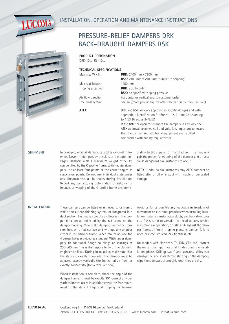
Product designation DRK-10…., RSK10…. technical sPecifications Max. size W x H: drK: 2400 mm x 7900 mm rsK: 7900 mm x 7900 mm (subject to shipping)Max. slat length: 1200 mmTripping pressure: drK: acc. to order rsK: no specified tripping pressureAir flow direction: horizontal or vertical acc. to customer orderFree cross section: >60 % ((more precise figures after calculation by manufacturer)
ateX DRK and RSK are only approved in specific designs and with appropriate identification for Zones 1, 2, 21 and 22 according to ATEX Directive 94/9/EC. If the fitter or operator changes the dampers in any way, the ATEX approval becomes null and void. It is important to ensure that the damper and additional equipment are installed in compliance with zoning requirements.
In principle, avoid all damage caused by external influ-ences. Never lift dampers by the slats or the outer lin-kages. Dampers with a maximum weight of 50 kg can be lifted by the C-profile frame. With heavier dam-pers, use at least four points at the corner angles as suspension points. Do not use individual slats under any circumstances as footholds during installation. Report any damage, e.g. deformation of slats, dents, impacts or warping of the C-profile frame etc. imme-
shiPment
installation
diately to the supplier or manufacturer. This may im-pair the proper functioning of the damper and at best cause dangerous circumstances to occur.
ateX: Under no circumstances may ATEX dampers be fitted after a fall or impact with visible or concealed damage
These dampers can be fitted or removed to or from a wall or an air conditioning system, or integrated in a duct section. First make sure the air flow is in the pro-per direction as indicated by the red arrow on the damper housing. Mount the dampers warp-free, ten-sion-free, on a flat surface and without any angular errors in the damper frame. When mounting, use the 4 corner holes provided as standard. With larger dam-pers, fit additional flange couplings at spacings of 200-500 mm. This is the responsibility of the planning engineer or fitter. During installation, make sure that the slats are exactly horizontal. The damper must be adjusted exactly vertically (for horizontal air flow) or exactly horizontally (for vertical air flow).
When installation is complete, check the angle of the damper frame. It must be exactly 90°. Correct any de-viations immediately. In addition check the free move-ment of the slats, linkage and tripping mechanism.
Avoid as far as possible any reduction in freedom of movement on customer premises when installing insu-lation materials, installation ducts, auxiliary structures etc. If this is not observed, it can lead to considerable disruptions in operation, e.g. slats rub against the dam-per frame, different tripping pressure, damper fails to open or close, reduced leak tightness, etc.
On models with side seals (Di, DIN, CEN etc.) protect the units from impurities of all kinds during the instal-lation phase. Drilling swarf and concrete chips can damage the side seals. Before starting up the dampers, wipe the side seals thoroughly until they are dry.
lucoma ag Weekendweg 5 · CH-3646 Einigen Switzerland Telefon +41 33 655 00 44 · Fax +41 33 655 00 45 · www. lucoma.com · [email protected]
installation
ifitting motors
adjusting triPPing Pressure
maintenance
sPecial instructions
Warranty
ateX: All relevant national and international stan-dards and regulations for Ex zones must be observed. On dampers with ATEX functionality in particular, the damper housing must be earthed using the earthing braids attached by the manufacturer. No mechanical changes may be made to the product. In addition do not attach any components (motors, limit switches, etc.) to the damper if they have not been analyzed for ignition risk by the appropriate manufacturers or ap-
proved for ATEX zones. It is prohibited to drill holes or fit bolts or screws in the interior of the dampers. This could lead to damage or disturb damper operation. If there is a risk at the factory that foreign bodies may enter the movement area of the slats, prevent them by suitable means (filters or catchment grills). This pre-vents the slats from sticking and the possibility of frictional heat developing.
rsK: Back-draught dampers have no specified open-ing pressure.
drK: The tripping pressure is adjusted according to customer specifications on a test stand at the manu-facturer›s factory. After installation, the tripping pres-
sure may be readjusted within a limited range as required. This occurs by sliding the tripping weight on the lever and refixing it in the required position. If the weights are arranged above a passageway, it is impe-rative to install a suitable catchment device.
Depending on the degree of soiling of the medium, carry out a dry clean from time to time; the seals in particular must be cleaned at regular intervals. In addi-tion, operate the dampers at regular intervals to test for their operability depending on the specific plant conditions. This prevents the adjacent slats from sti-cking. The slide bearings can be blown off using com-
pressed air as required, although they are basically maintenance-free (lubrication). Otherwise the DRK models operate maintenance-free.Only LUCOMA genuine spare parts may be used for all repair and maintenance work.
ateX: All relevant national and international stan-dards and regulations for Ex zones must be observed.
Before using LUCOMA dampers in areas with increased requirements, report the prevailing conditions to the manufacturer so that the correct damper materials can be selected. The correct damper materials are
especially important in factories with chemically laden atmospheres, electroplating shops, battery rooms etc.
When installed and operated properly, the warranty according to the Swiss Code of Obligations is 2 years.
ateX: Dampers operated in ATEX zones should be replaced every 10 years for safety reasons.
lucoma ag Weekendweg 5 · CH-3646 Einigen Switzerland Telefon +41 33 655 00 44 · Fax +41 33 655 00 45 · www. lucoma.com · [email protected]
InstallatIon, operatIon and maIntenance InstructIons
Pressure-relief damPers drKbacK-draught damPers rsK
DRK and RSK basically function without a motor. How-ever, for special applications, a motor may be fitted using a special bracket. When fitting motors, always comply with the maintenance and fitting instructions of the motor manufacturer. With lift motors, pay spe-cial attention to power transmission at right angles to ensure trouble-free operation of the damper. Especially with drive motors which have high closing speeds, pay special attention to adequate protection of the move-
ment areas (slats and linkages) to prevent reaching into the mechanisms. Responsibility lies with the ope-rator.
ateX: All relevant national and international stan-dards and regulations for Ex zones must be observed. In particular, only drive motors, limit switches etc. with special approval for use in ATEX zones are allowed. Responsibility lies with the operator.