Presentation on ULP GFSK PHY proposal November 2013 · 2013-11-14 · of IEEE and may be made...
50
IEEE-15-13-0709-00-004q Submission November 2013 Henk de Ruijter, Ping Xiong (Silicon Labs) Slide 1 Project: IEEE P802.15 Working Group for Wireless Personal Area Networks (WPANs) Submission Title: Presentation on ULP GFSK PHY proposal Date Submitted: November 2013 Source: Henk de Ruijter, Ping Xiong, Silicon Labs 940 Stewart Dr, Sunnyvale, CA, USA Abstract: Presentation on ULP GFSK PHY proposal Purpose: Providing direction towards a ULP PHY standard Notice: This document has been prepared to assist the IEEE P802.15. It is offered as a basis for discussion and is not binding on the contributing individual(s) or organization(s). The material in this document is subject to change in form and content after further study. The contributor(s) reserve(s) the right to add, amend or withdraw material contained herein. Release: The contributor acknowledges and accepts that this contribution becomes the property of IEEE and may be made publicly available by P802.15.
Transcript of Presentation on ULP GFSK PHY proposal November 2013 · 2013-11-14 · of IEEE and may be made...
IEEE-15-13-0709-00-004q
Submission
November 2013
Henk de Ruijter, Ping Xiong (Silicon Labs) Slide 1
Project: IEEE P802.15 Working Group for Wireless Personal Area Networks (WPANs)
Submission Title: Presentation on ULP GFSK PHY proposal
Date Submitted: November 2013
Source: Henk de Ruijter, Ping Xiong, Silicon Labs
940 Stewart Dr, Sunnyvale, CA, USA
Abstract: Presentation on ULP GFSK PHY proposal
Purpose: Providing direction towards a ULP PHY standard
Notice: This document has been prepared to assist the IEEE P802.15. It is offered as a basis
for discussion and is not binding on the contributing individual(s) or organization(s). The
material in this document is subject to change in form and content after further study. The
contributor(s) reserve(s) the right to add, amend or withdraw material contained herein.
Release: The contributor acknowledges and accepts that this contribution becomes the property
of IEEE and may be made publicly available by P802.15.
IEEE-15-13-0709-00-004q
Submission
November 2013
Slide 2
Ultra Low Power GFSK PHY proposal (presentation on draft proposal 15-13-0630-00-ULP-FSK-PHY-proposal)
Henk de Ruijter, Ping Xiong
November, 2013
Henk de Ruijter, Ping Xiong (Silicon Labs)
IEEE-15-13-0709-00-004q
Submission
November 2013
Slide 3
Outline:
• Introduction
• ULP-GFSK proposal
• Evaluation using TGD
• Abbreviations
• References
• Appendix
Henk de Ruijter, Ping Xiong (Silicon Labs)
IEEE-15-13-0709-00-004q
Submission
November 2013
Slide 4
Introduction
Henk de Ruijter, Ping Xiong (Silicon Labs)
IEEE-15-13-0709-00-004q
Submission
November 2013
Slide 5
Summary:
This proposal, ULP-GFSK PHY, can be considered as an extension, adding low power options, to the MR-FSK PHY as defined in the 802.15.4g amendment [1]
This will have the following benefits:
• The similarities to the MR_FSK PHY will reduce development cost for implementers as well as chip vendors.
• Piggyback on an existing and successful PHY standard will help to expedite industrial acceptance.
Henk de Ruijter, Ping Xiong (Silicon Labs)
IEEE-15-13-0709-00-004q
Submission
November 2013
Slide 6 Henk de Ruijter, Ping Xiong (Silicon Labs)
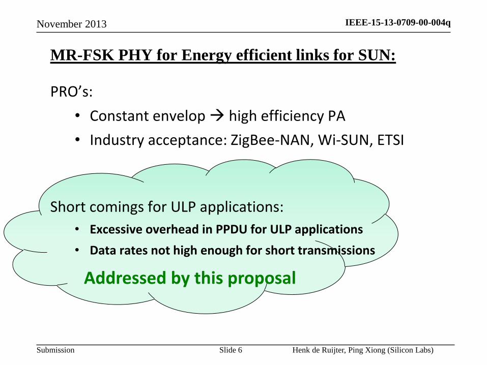
MR-FSK PHY for Energy efficient links for SUN:
PRO’s:
• Constant envelop high efficiency PA
• Industry acceptance: ZigBee-NAN, Wi-SUN, ETSI
Short comings for ULP applications:
• Excessive overhead in PPDU for ULP applications
• Data rates not high enough for short transmissions
Addressed by this proposal
IEEE-15-13-0709-00-004q
Submission
November 2013
Slide 7
Power savings of this proposal:
Power is being saved by:
• Increase data rate to reduce the receiver and transmitter ON time.
• Double Data Rate mode (DDR) without re-sync required
Additional power is being saved by reducing overhead:
• 1 octet PHY header (vs 2 octet in MR-FSK PHY)
• Optional 2 octet preamble (vs 4 octet in MR-FSK PHY)
Henk de Ruijter, Ping Xiong (Silicon Labs)
IEEE-15-13-0709-00-004q
Submission
November 2013
Slide 8
ULP-GFSK PHY proposal
Henk de Ruijter, Ping Xiong (Silicon Labs)
IEEE-15-13-0709-00-004q
Submission
November 2013
Slide 9 Henk de Ruijter, Ping Xiong (Silicon Labs)
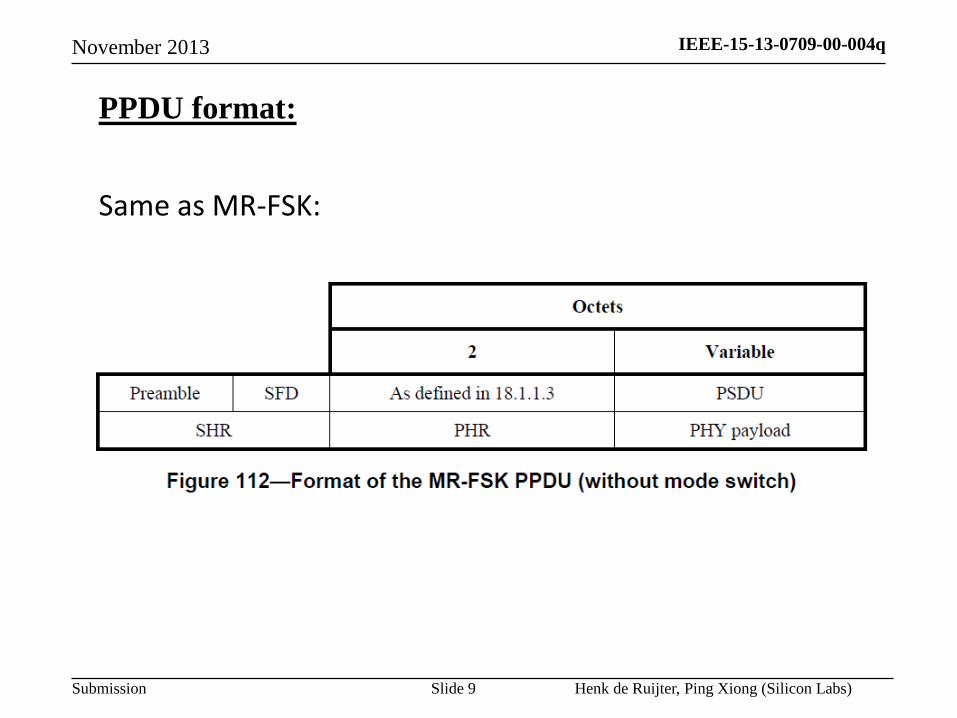
PPDU format:
Same as MR-FSK:
IEEE-15-13-0709-00-004q
Submission
November 2013
Slide 10 Henk de Ruijter, Ping Xiong (Silicon Labs)
Preamble:
To reduce overhead (and save power):
• The minimum preamble for the ULP-GFSK PHY is reduced to 2 octet.
• The PHY PIB attribute “phyFSKPreambleLength” will be made available for ULP-FSK. The description in table 71 needs to reflect that and describe the related value range of 2 – 1000 for ULP-FSK.
Common with MR-FSK:
• The Preamble field shall contain phyFSKPreambleLength (as defined in 9.3, see 802.15.4g-2012 [1]) multiples of the 8-bit sequence “01010101” for filtered 2FSK.

IEEE-15-13-0709-00-004q
Submission
November 2013
Slide 11 Henk de Ruijter, Ping Xiong (Silicon Labs)
SFD:
The SFD in ULP-GFSK is specified the same
as for MR-FSK. See section 18.1.1.2 [1].

IEEE-15-13-0709-00-004q
Submission
November 2013
Slide 12 Henk de Ruijter, Ping Xiong (Silicon Labs)
Mandatory PHY Header (PHR):
The ULP-FSK PHY shall support the PHY Header as
shown in Figure 114 [1].
• This PHY Header is also mandatory for MR-FSK
• In MR-FSK: “All reserved fields shall be set to
zero upon transmission and shall be ignored
upon reception”
• R1-R0 are used by the ULP-GFSK PHY
IEEE-15-13-0709-00-004q
Submission
November 2013
Slide 13
Resevered bits R1-R0:
R1-R0 are used in the ULP-FSK PHY as follows:
• R0 = SPH
Short PHR. When this bit is set while MS=”0”, the PHY Header (PHR) shown on the next slide shall be used.
• R1 = DDR
Double Data Rate. When this bit is set the data rate across the PSDU shall be doubled by applying 4GFSK modulation as appose to 2GFSK which is used during SHR and PHR. One symbol rate is maintained across the entire PPDU and the outer deviation of the 4GFSK is equal to the 2GFSK deviation to support seamless transition from PHR in 2GFSK to PSDU in 4GFSK.
Henk de Ruijter, Ping Xiong (Silicon Labs)
IEEE-15-13-0709-00-004q
Submission
November 2013
Slide 14 Henk de Ruijter, Ping Xiong (Silicon Labs)
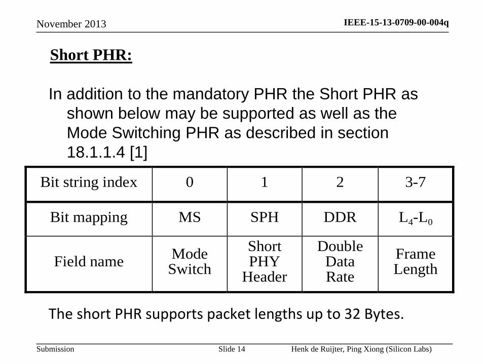
Short PHR:
In addition to the mandatory PHR the Short PHR as
shown below may be supported as well as the
Mode Switching PHR as described in section
18.1.1.4 [1]
The short PHR supports packet lengths up to 32 Bytes.
Bit string index 0 1 2 3-7
Bit mapping MS SPH DDR L4-L0
Field name Mode Switch
Short PHY
Header
Double Data Rate
Frame Length

IEEE-15-13-0709-00-004q
Submission
November 2013
Slide 15
Specification of MS/SPH and DDR:
Note: The DDR bit will be ignored when 4(G)FSK is used across the entire PPDU.
Henk de Ruijter, Ping Xiong (Silicon Labs)
MS SPH DDR PHY Header Modulation on PSDU Frame
Check Sum
Data
Whitening
0 0 0
Mandatory
PHR, see slide
11
Same as SHR and PHR
Selected by
FCS bit in
PHR
Selected by
DW bit in
PHR
1 X X
Mode Switch
PHR, see Figure
115 [1]
Same as SHR and PHR
Selected by
FCS bit in
PHR
Selected by
DW bit in
PHR
0 1 0 Short PHR, see
slide 13. Same as SHR and PHR FCS = 16 bit DW enabled
0 1 1 Short PHR, see
slide 13
4GFSK, same symbol
rate as SHR and PHR FCS = 16 bit DW enabled
0 0 1
Mandatory
PHR, see slide
11
4GFSK, same symbol
rate as SHR and PHR
Selected by
FCS bit in
PHR
Selected by
DW bit in
PHR

IEEE-15-13-0709-00-004q
Submission
November 2013
Slide 16
Modulation: = also used in MR_FSK
Henk de Ruijter, Ping Xiong (Silicon Labs)
ULP-FSK
Operating
Mode
Data
Rate
[kbps]
Channel
Spacing
[kHz]
Mod type Mod-
index/BT 20dB BW
Adjacent
channel
leakage
(dB)
Sensitivity
PER=1%
NF=10dB
[dBm]
4 4.8 12.5 2GFSK 1/0.5 10 -42 -115
5 9.6 12.5 4GFSK 0.333/0.5 8.8 -44 -109
6 9.6 25 2GFSK 1/0.5 20 -42 -112
7 19.2 25 4GFSK 0.333/0.5 18 -44 -106
8 50 200 2GFSK 1/0.5 104 -68 -105
9 100 200 4GFSK 0.333/0.5 92 -73 -99
10 150 400 2GFSK 1/0.5 312 -42 -100
11 300 400 4GFSK 0.333/0.5 276 -45 -94
12 400 1000 2GFSK 1/0.5 836 -41 -96
13 800 1000 4GFSK 0.333/0.5 740 -42 -90
IEEE-15-13-0709-00-004q
Submission
November 2013
Slide 17
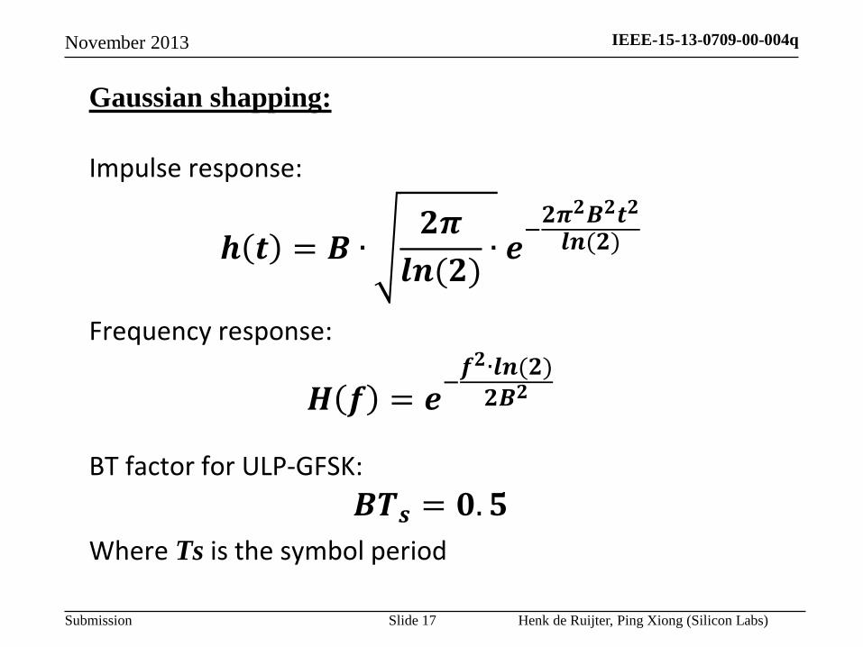
Gaussian shapping:
Impulse response:
𝒉 𝒕 = 𝑩 ∙𝟐𝝅
𝒍𝒏(𝟐)∙ 𝒆
−𝟐𝝅𝟐𝑩𝟐𝒕𝟐
𝒍𝒏(𝟐)
Frequency response:
𝑯 𝒇 = 𝒆−𝒇𝟐∙𝒍𝒏(𝟐)
𝟐𝑩𝟐
BT factor for ULP-GFSK:
𝑩𝑻𝒔 = 𝟎. 𝟓
Where Ts is the symbol period
Henk de Ruijter, Ping Xiong (Silicon Labs)
IEEE-15-13-0709-00-004q
Submission
November 2013
Slide 18
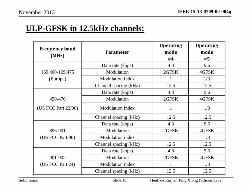
ULP-GFSK in 12.5kHz channels:
Henk de Ruijter, Ping Xiong (Silicon Labs)
Frequency band
(MHz) Parameter
Operating
mode
#4
Operating
mode
#5
Data rate (kbps) 4.8 9.6
169.400-169.475 Modulation 2GFSK 4GFSK
(Europe) Modulation index 1 1/3
Channel spacing (kHz) 12.5 12.5
Data rate (kbps) 4.8 9.6
450-470 Modulation 2GFSK 4GFSK
(US FCC Part 22/90) Modulation index 1 1/3
Channel spacing (kHz) 12.5 12.5
Data rate (kbps) 4.8 9.6
896-901 Modulation 2GFSK 4GFSK
(US FCC Part 90) Modulation index 1 1/3
Channel spacing (kHz) 12.5 12.5
Data rate (kbps) 4.8 9.6
901-902 Modulation 2GFSK 4GFSK
(US FCC Part 24) Modulation index 1 1/3
Channel spacing (kHz) 12.5 12.5
IEEE-15-13-0709-00-004q
Submission
November 2013
Slide 19
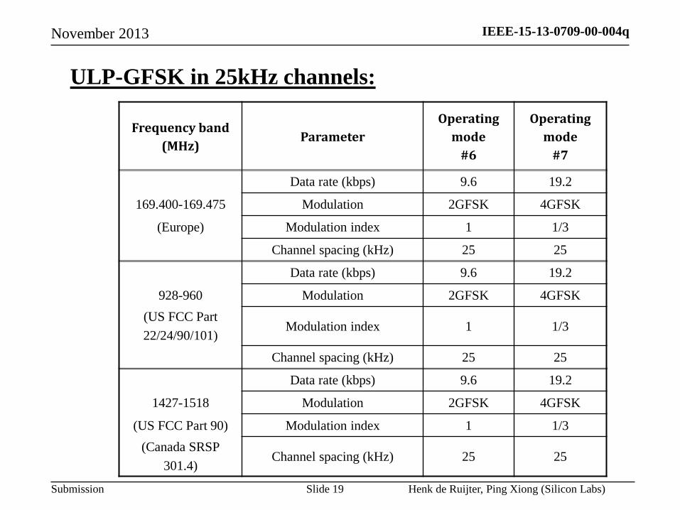
ULP-GFSK in 25kHz channels:
Henk de Ruijter, Ping Xiong (Silicon Labs)
Frequency band
(MHz) Parameter
Operating
mode
#6
Operating
mode
#7
Data rate (kbps) 9.6 19.2
169.400-169.475 Modulation 2GFSK 4GFSK
(Europe) Modulation index 1 1/3
Channel spacing (kHz) 25 25
Data rate (kbps) 9.6 19.2
928-960 Modulation 2GFSK 4GFSK
(US FCC Part
22/24/90/101) Modulation index 1 1/3
Channel spacing (kHz) 25 25
Data rate (kbps) 9.6 19.2
1427-1518 Modulation 2GFSK 4GFSK
(US FCC Part 90) Modulation index 1 1/3
(Canada SRSP
301.4) Channel spacing (kHz) 25 25

IEEE-15-13-0709-00-004q
Submission
November 2013
Slide 20
ULP-GFSK in 200 – 400 kHz channels (1):
Henk de Ruijter, Ping Xiong (Silicon Labs)
Frequency
band
(MHz)
Parameter
Operating
mode
#8
Operating
mode
#9
Operating
mode
#10
Operating
mode
#11
Data rate (kbps) 50 100 150 300
470-510 Modulation 2GFSK 4GFSK 2GFSK 4GFSK
(China) Modulation index 1 1/3 1 1/3
Channel spacing (kHz) 200 200 400 400
Data rate (kbps) 50 100 150 300
779-787 Modulation 2GFSK 4GFSK 2GFSK 4GFSK
(China) Modulation index 1 1/3 1 1/3
Channel spacing (kHz) 200 200 400 400
Data rate (kbps) 50 100 150 300
863-876 915-921 Modulation 2GFSK 4GFSK 2GFSK 4GFSK
(Europe) Modulation index 1 1/3 1 1/3
Channel spacing (kHz) 200 200 400 400
IEEE-15-13-0709-00-004q
Submission
November 2013
Slide 21
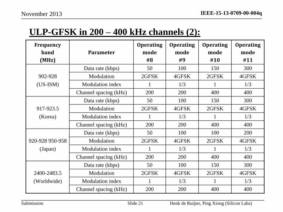
ULP-GFSK in 200 – 400 kHz channels (2):
Henk de Ruijter, Ping Xiong (Silicon Labs)
Frequency
band
(MHz)
Parameter
Operating
mode
#8
Operating
mode
#9
Operating
mode
#10
Operating
mode
#11
Data rate (kbps) 50 100 150 300
902-928 Modulation 2GFSK 4GFSK 2GFSK 4GFSK
(US-ISM) Modulation index 1 1/3 1 1/3
Channel spacing (kHz) 200 200 400 400
Data rate (kbps) 50 100 150 300
917-923.5 Modulation 2GFSK 4GFSK 2GFSK 4GFSK
(Korea) Modulation index 1 1/3 1 1/3
Channel spacing (kHz) 200 200 400 400
Data rate (kbps) 50 100 100 200
920-928 950-958 Modulation 2GFSK 4GFSK 2GFSK 4GFSK
(Japan) Modulation index 1 1/3 1 1/3
Channel spacing (kHz) 200 200 400 400
Data rate (kbps) 50 100 150 300
2400-2483.5 Modulation 2GFSK 4GFSK 2GFSK 4GFSK
(Worldwide) Modulation index 1 1/3 1 1/3
Channel spacing (kHz) 200 200 400 400
IEEE-15-13-0709-00-004q
Submission
November 2013
Slide 22
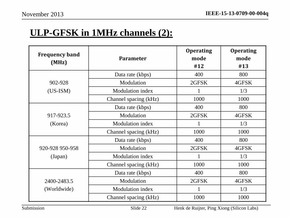
ULP-GFSK in 1MHz channels (2):
Henk de Ruijter, Ping Xiong (Silicon Labs)
Frequency band
(MHz) Parameter
Operating
mode
#12
Operating
mode
#13
Data rate (kbps) 400 800
902-928 Modulation 2GFSK 4GFSK
(US-ISM) Modulation index 1 1/3
Channel spacing (kHz) 1000 1000
Data rate (kbps) 400 800
917-923.5 Modulation 2GFSK 4GFSK
(Korea) Modulation index 1 1/3
Channel spacing (kHz) 1000 1000
Data rate (kbps) 400 800
920-928 950-958 Modulation 2GFSK 4GFSK
(Japan) Modulation index 1 1/3
Channel spacing (kHz) 1000 1000
2400-2483.5
(Worldwide)
Data rate (kbps) 400 800
Modulation 2GFSK 4GFSK
Modulation index 1 1/3
Channel spacing (kHz) 1000 1000
IEEE-15-13-0709-00-004q
Submission
November 2013
Slide 23
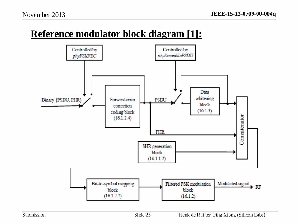
Reference modulator block diagram [1]:
Henk de Ruijter, Ping Xiong (Silicon Labs)

IEEE-15-13-0709-00-004q
Submission
November 2013
Slide 24
Radio frequency tolerance, same as in MR-FSK [1]:
Henk de Ruijter, Ping Xiong (Silicon Labs)

IEEE-15-13-0709-00-004q
Submission
November 2013
Slide 25
Leveraging MR-FSK [1]:
The ULP-GFSK PHY is using identical specifications for:
• Bit to Symbol Mapping
• Modulation quality
• Zero crossing tolerance
• Forward Error Correction (Convolution coding, K=4)
• Symbol interleaving
• Data Whitening
• Mode switching
• RF specification
Henk de Ruijter, Ping Xiong (Silicon Labs)
IEEE-15-13-0709-00-004q
Submission
November 2013
Slide 26
Evaluation of ULP-GFSK PHY proposal
Henk de Ruijter, Ping Xiong (Silicon Labs)

IEEE-15-13-0709-00-004q
Submission
PSDU efficiency:
Definition used here:
Where: Ttotal = total transmit on time
Tpayload = time of payload transmission
Notes: - ULP-GFSK PHY with 2 Byte preamble, Short PHR and 2 Byte FCS
- A 5 Byte PDSU might be an acknowledgement frame
November 2013
Slide 27 Henk de Ruijter, Ping Xiong (Silicon Labs)
PSDU
# of
Bytes
FCS #
of Bytes
ηPSDU
MR-
FSK
ULP-
GFSK
5 2 0.231 0.300
32 2 0.725 0.783
23% power saving 7.4% power saving
η𝑃𝑆𝐷𝑈
=𝑇𝑝𝑎𝑦𝑙𝑜𝑎𝑑
𝑇𝑡𝑜𝑡𝑎𝑙
IEEE-15-13-0709-00-004q
Submission
November 2013
Slide 28
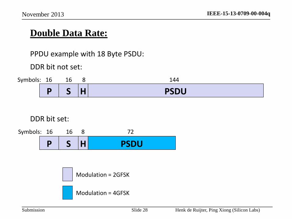
Double Data Rate:
PPDU example with 18 Byte PSDU:
DDR bit not set:
DDR bit set:
Henk de Ruijter, Ping Xiong (Silicon Labs)
H P S PSDU
H P S PSDU
Symbols: 16 16 8 144
Symbols: 16 16 8 72
Modulation = 2GFSK
Modulation = 4GFSK
IEEE-15-13-0709-00-004q
Submission
November 2013
Slide 29
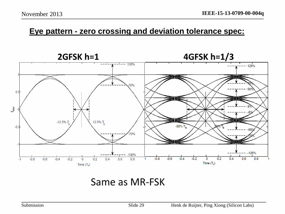
Eye pattern - zero crossing and deviation tolerance spec:
Henk de Ruijter, Ping Xiong (Silicon Labs)
2GFSK h=1 4GFSK h=1/3
Same as MR-FSK
IEEE-15-13-0709-00-004q
Submission
November 2013
Slide 30
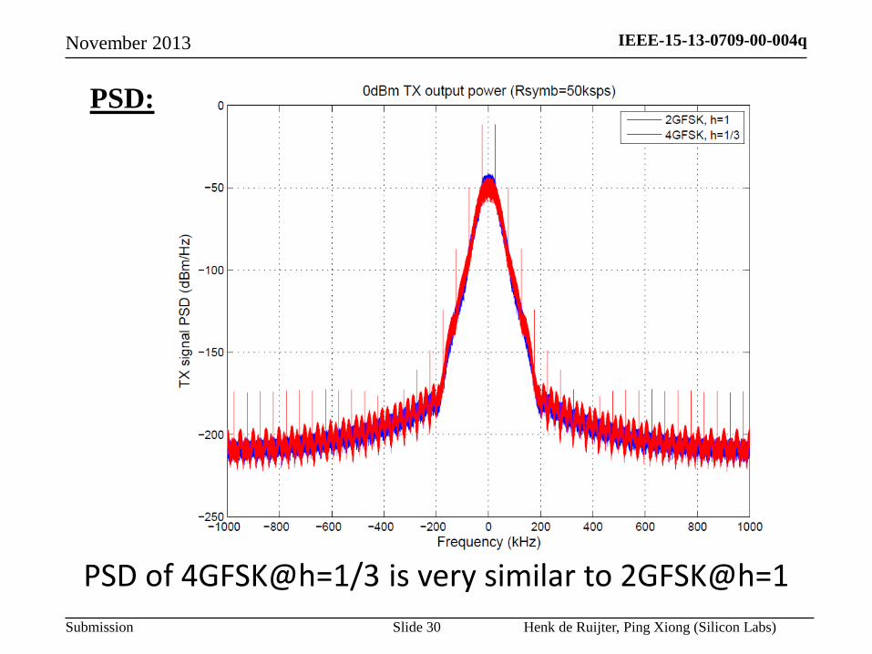
PSD:
Henk de Ruijter, Ping Xiong (Silicon Labs)
PSD of 4GFSK@h=1/3 is very similar to 2GFSK@h=1
IEEE-15-13-0709-00-004q
Submission
November 2013
Slide 31
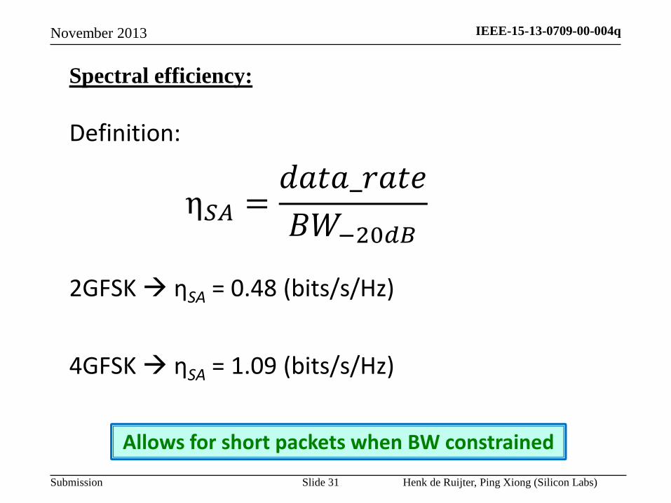
Spectral efficiency:
Definition:
2GFSK ηSA = 0.48 (bits/s/Hz)
4GFSK ηSA = 1.09 (bits/s/Hz)
Henk de Ruijter, Ping Xiong (Silicon Labs)
η𝑆𝐴 =𝑑𝑎𝑡𝑎_𝑟𝑎𝑡𝑒
𝐵𝑊−20𝑑𝐵
Allows for short packets when BW constrained

IEEE-15-13-0709-00-004q
Submission
November 2013
Slide 32
PSD of 4GFSK@h=1/3 compared to MSK:
Note: Both MSK and OQPSK(half sine shaped) have significant spectral leakage
Henk de Ruijter, Ping Xiong (Silicon Labs)

IEEE-15-13-0709-00-004q
Submission
November 2013
Slide 33
20 dB signal Bandwidth:
Henk de Ruijter, Ping Xiong (Silicon Labs)
ULP-FSK
Operating
Mode
Data
Rate
[kbps]
Channel
Spacing
[kHz]
Mod type Mod-
index/BT
20dB BW
(kHz)
Adjacent
channel
leakage
(dB)
Sensitivity
PER=1%
NF=10dB
[dBm]
4 4.8 12.5 2GFSK 1/0.5 10 -42 -115
5 9.6 12.5 4GFSK 0.333/0.5 8.8 -44 -109
6 9.6 25 2GFSK 1/0.5 20 -42 -112
7 19.2 25 4GFSK 0.333/0.5 18 -44 -106
8 50 200 2GFSK 1/0.5 104 -68 -105
9 100 200 4GFSK 0.333/0.5 92 -73 -99
10 150 400 2GFSK 1/0.5 312 -42 -100
11 300 400 4GFSK 0.333/0.5 276 -45 -94
12 400 1000 2GFSK 1/0.5 836 -41 -96
13 800 1000 4GFSK 0.333/0.5 740 -42 -90
IEEE-15-13-0709-00-004q
Submission
November 2013
Slide 34
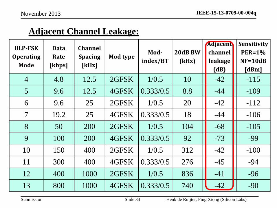
Adjacent Channel Leakage:
Henk de Ruijter, Ping Xiong (Silicon Labs)
ULP-FSK
Operating
Mode
Data
Rate
[kbps]
Channel
Spacing
[kHz]
Mod type Mod-
index/BT
20dB BW
(kHz)
Adjacent
channel
leakage
(dB)
Sensitivity
PER=1%
NF=10dB
[dBm]
4 4.8 12.5 2GFSK 1/0.5 10 -42 -115
5 9.6 12.5 4GFSK 0.333/0.5 8.8 -44 -109
6 9.6 25 2GFSK 1/0.5 20 -42 -112
7 19.2 25 4GFSK 0.333/0.5 18 -44 -106
8 50 200 2GFSK 1/0.5 104 -68 -105
9 100 200 4GFSK 0.333/0.5 92 -73 -99
10 150 400 2GFSK 1/0.5 312 -42 -100
11 300 400 4GFSK 0.333/0.5 276 -45 -94
12 400 1000 2GFSK 1/0.5 836 -41 -96
13 800 1000 4GFSK 0.333/0.5 740 -42 -90

IEEE-15-13-0709-00-004q
Submission
November 2013
Slide 35
Eb/No in AWGN:
Henk de Ruijter, Ping Xiong (Silicon Labs)
1% PER

IEEE-15-13-0709-00-004q
Submission
November 2013
Slide 36
RX sensitivity (non-coherent demodulator, 20B PSDU):
Henk de Ruijter, Ping Xiong (Silicon Labs)
ULP-FSK
Operating
Mode
Data
Rate
[kbps]
Channel
Spacing
[kHz]
Mod type Mod-
index/BT
20dB BW
(kHz)
Adjacent
channel
leakage
(dB)
Sensitivity
PER=1%
NF=10dB
[dBm]
4 4.8 12.5 2GFSK 1/0.5 10 -42 -115
5 9.6 12.5 4GFSK 0.333/0.5 8.8 -44 -109
6 9.6 25 2GFSK 1/0.5 20 -42 -112
7 19.2 25 4GFSK 0.333/0.5 18 -44 -106
8 50 200 2GFSK 1/0.5 104 -68 -105
9 100 200 4GFSK 0.333/0.5 92 -73 -99
10 150 400 2GFSK 1/0.5 312 -42 -100
11 300 400 4GFSK 0.333/0.5 276 -45 -94
12 400 1000 2GFSK 1/0.5 836 -41 -96
13 800 1000 4GFSK 0.333/0.5 740 -42 -90
IEEE-15-13-0709-00-004q
Submission
November 2013
Slide 37
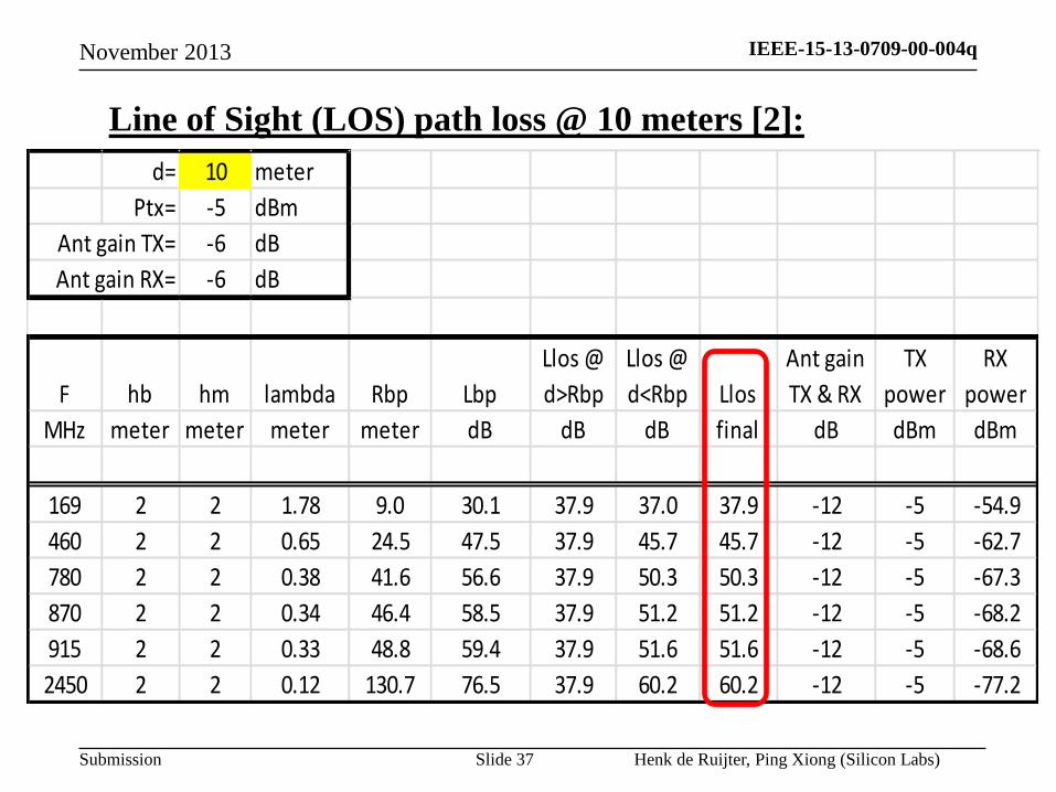
Line of Sight (LOS) path loss @ 10 meters [2]:
Henk de Ruijter, Ping Xiong (Silicon Labs)
d= 10 meter
Ptx= -5 dBm
Ant gain TX= -6 dB
Ant gain RX= -6 dB
F hb hm lambda Rbp Lbp
Llos @
d>Rbp
Llos @
d<Rbp Llos
Ant gain
TX & RX
TX
power
RX
power
MHz meter meter meter meter dB dB dB final dB dBm dBm
169 2 2 1.78 9.0 30.1 37.9 37.0 37.9 -12 -5 -54.9
460 2 2 0.65 24.5 47.5 37.9 45.7 45.7 -12 -5 -62.7
780 2 2 0.38 41.6 56.6 37.9 50.3 50.3 -12 -5 -67.3
870 2 2 0.34 46.4 58.5 37.9 51.2 51.2 -12 -5 -68.2
915 2 2 0.33 48.8 59.4 37.9 51.6 51.6 -12 -5 -68.6
2450 2 2 0.12 130.7 76.5 37.9 60.2 60.2 -12 -5 -77.2

IEEE-15-13-0709-00-004q
Submission
November 2013
Slide 38
ITU indoor channel model [2]:
Power Delay Profile:
Henk de Ruijter, Ping Xiong (Silicon Labs)
Tap Relative delay
(ns)
Average power
(dB)
Doppler
spectrum
1 0 0 Flat
2 50 -3 Flat
3 110 -10 Flat
4 170 -18 Flat
5 290 -26 Flat
6 310 -32 Flat
IEEE-15-13-0709-00-004q
Submission
November 2013
Slide 39
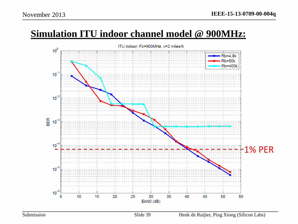
Simulation ITU indoor channel model @ 900MHz:
Henk de Ruijter, Ping Xiong (Silicon Labs)
1% PER
IEEE-15-13-0709-00-004q
Submission
November 2013
Slide 40
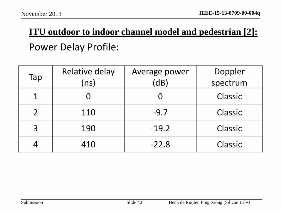
ITU outdoor to indoor channel model and pedestrian [2]:
Power Delay Profile:
Henk de Ruijter, Ping Xiong (Silicon Labs)
Tap Relative delay
(ns) Average power
(dB) Doppler
spectrum
1 0 0 Classic
2 110 -9.7 Classic
3 190 -19.2 Classic
4 410 -22.8 Classic

IEEE-15-13-0709-00-004q
Submission
November 2013
Slide 41
Simulation ITU indoor channel model @ 900MHz:
Henk de Ruijter, Ping Xiong (Silicon Labs)
1% PER
IEEE-15-13-0709-00-004q
Submission
November 2013
Slide 42
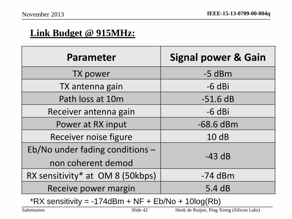
Link Budget @ 915MHz:
*RX sensitivity = -174dBm + NF + Eb/No + 10log(Rb)
Henk de Ruijter, Ping Xiong (Silicon Labs)
Parameter Signal power & Gain
TX power -5 dBm
TX antenna gain -6 dBi
Path loss at 10m -51.6 dB
Receiver antenna gain -6 dBi
Power at RX input -68.6 dBm
Receiver noise figure 10 dB
Eb/No under fading conditions –
non coherent demod -43 dB
RX sensitivity* at OM 8 (50kbps) -74 dBm
Receive power margin 5.4 dB

IEEE-15-13-0709-00-004q
Submission
November 2013
Slide 43
Receiver power consumption (1):
Power consumption in receiver depends on:
• Noise Figure
• Selectivity and blocking performance
• Demodulator sensitivity
E.g. the adjacent channel selectivity can be calculated as follows:
𝐴𝑑𝑗𝐶𝑅 = 10 ∗ log10
10𝑃𝑁𝐴𝑑𝑗𝐶ℎ+𝑆𝑁𝑅
10 + 10𝐶𝐹𝐴𝑑𝑗𝐶ℎ+𝑆𝑁𝑅
10
Where:
PNAdjCh is the LO phase noise power integrated over the adjacent channel in dBc
CFAdjCh is the suppression of the adjacent channel relative to the pass band in dB
SNR is the signal to noise ratio required at the demodulator input for the specified PER in dB
Henk de Ruijter, Ping Xiong (Silicon Labs)

IEEE-15-13-0709-00-004q
Submission
November 2013
Slide 44
Receiver power consumption (2):
Based on silicon available today:
• PLL tuning system ~ 11mW
• LNA/Mixer + demod ~ 7mW
• Total consumed power: ~18mW
• Higher performance than needed for ULP applications:
NF = 8dB, ULP TGD specifies 10dB
Adjacent Channel selectivity = -56dB
Down scaled performance is likely to meet the TG4q requirement of 15mW.
Henk de Ruijter, Ping Xiong (Silicon Labs)

IEEE-15-13-0709-00-004q
Submission
November 2013
Slide 45
Transmitter power consumption:
Power consumption in transmitter depends on: • PA efficiency
• Spurious emission requirements
Phase Noise on RF signal
From existing silicon: • PA power consumption < 1mW at -5dBm RF power
• RF carrier generation ~12mW
• For high performance / low phase noise carrier
• Already lower than TG4q requirement (15mW)
Henk de Ruijter, Ping Xiong (Silicon Labs)
IEEE-15-13-0709-00-004q
Submission
November 2013
Slide 46
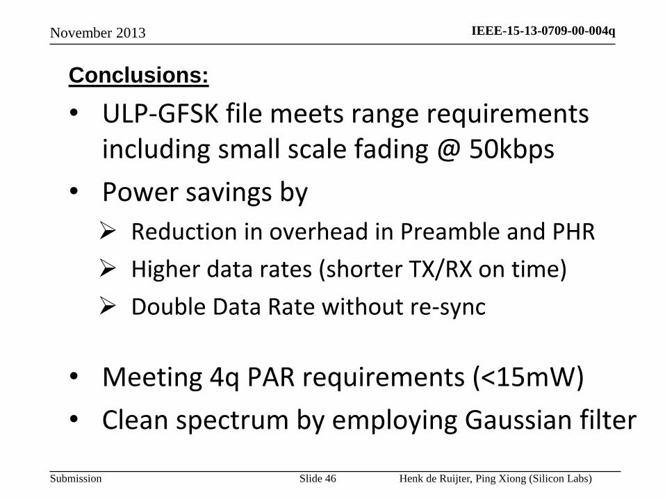
Conclusions:
• ULP-GFSK file meets range requirements including small scale fading @ 50kbps
• Power savings by
Reduction in overhead in Preamble and PHR
Higher data rates (shorter TX/RX on time)
Double Data Rate without re-sync
• Meeting 4q PAR requirements (<15mW)
• Clean spectrum by employing Gaussian filter
Henk de Ruijter, Ping Xiong (Silicon Labs)
IEEE-15-13-0709-00-004q
Submission
November 2013
Slide 47
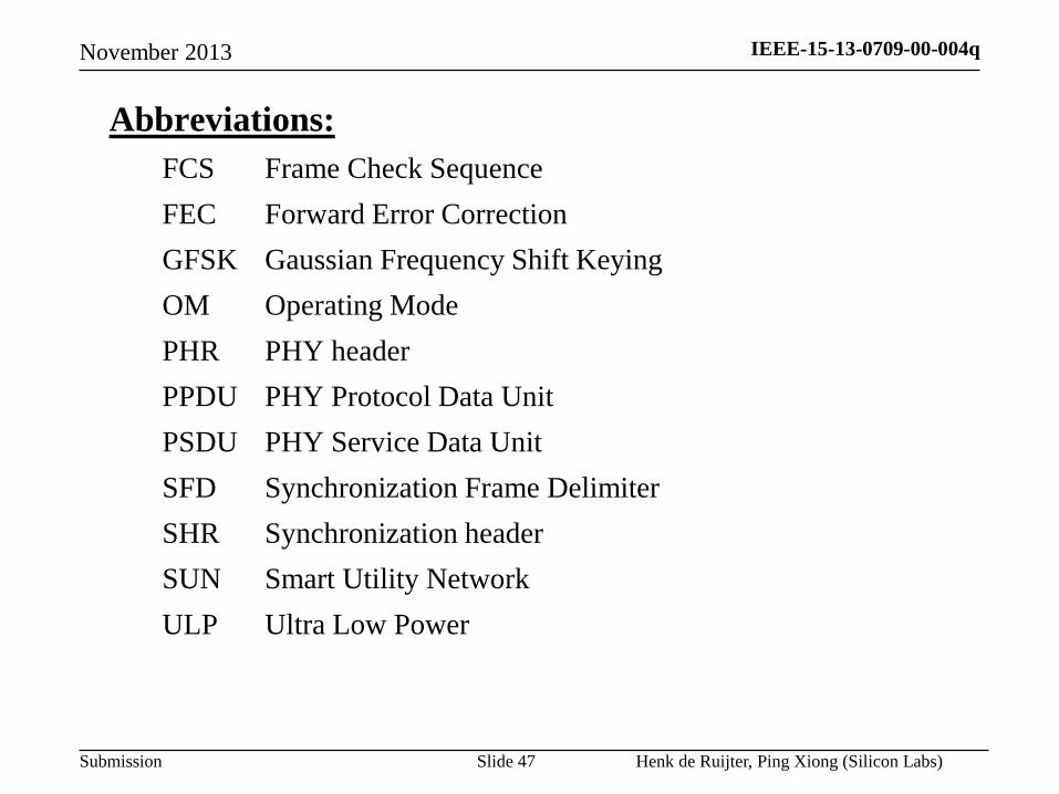
Abbreviations:
FCS Frame Check Sequence
FEC Forward Error Correction
GFSK Gaussian Frequency Shift Keying
OM Operating Mode
PHR PHY header
PPDU PHY Protocol Data Unit
PSDU PHY Service Data Unit
SFD Synchronization Frame Delimiter
SHR Synchronization header
SUN Smart Utility Network
ULP Ultra Low Power
Henk de Ruijter, Ping Xiong (Silicon Labs)

IEEE-15-13-0709-00-004q
Submission
November 2013
Slide 48
REFERENCES:
[1] IEEE802.15.4g-2012
[2] 15-13-0329-01-004q-channel-models-for-IEEE-802-15-4q
[3] 15-13-0341-03-004q-tg4q-tgd-draft
[4] IEEE802.15.4-2011
[5] 15-13-0630-01-ULP-FSK-PHY-proposal.pdf
Henk de Ruijter, Ping Xiong (Silicon Labs)

IEEE-15-13-0709-00-004q
Submission
November 2013
Slide 49
APPENDIX A – Frame structures – 802.15.4-2011:
Frame control field:
Address information:
MAC data frame:
Acknowledgement frame:
Henk de Ruijter, Ping Xiong (Silicon Labs)
IEEE-15-13-0709-00-004q
Submission
November 2013
Slide 50
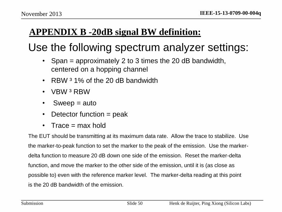
APPENDIX B -20dB signal BW definition:
Use the following spectrum analyzer settings: • Span = approximately 2 to 3 times the 20 dB bandwidth,
centered on a hopping channel
• RBW ³ 1% of the 20 dB bandwidth
• VBW ³ RBW
• Sweep = auto
• Detector function = peak
• Trace = max hold
The EUT should be transmitting at its maximum data rate. Allow the trace to stabilize. Use
the marker-to-peak function to set the marker to the peak of the emission. Use the marker-
delta function to measure 20 dB down one side of the emission. Reset the marker-delta
function, and move the marker to the other side of the emission, until it is (as close as
possible to) even with the reference marker level. The marker-delta reading at this point
is the 20 dB bandwidth of the emission.
Henk de Ruijter, Ping Xiong (Silicon Labs)