PRESENTATION
18
RESISTORS CAPACITORS INDUCTORS TAIMOOR TAHIR ABBAS AHMED SIDDIQUE HASSAN SAEED IBRAHIM ZAFAR SYED QASIM RAZA ZAIDI SAQIB JAVED
-
Upload
taimoor-tahir -
Category
Documents
-
view
10 -
download
0
Transcript of PRESENTATION

RESISTORSCAPACITORS
INDUCTORS
TAIMOOR TAHIR
ABBAS AHMED SIDDIQUE
HASSAN SAEED
IBRAHIM ZAFAR
SYED QASIM RAZA ZAIDI
SAQIB JAVED

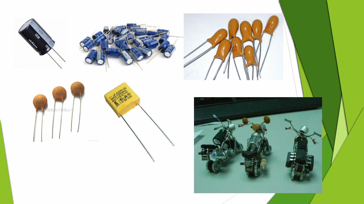
CAPACITORS
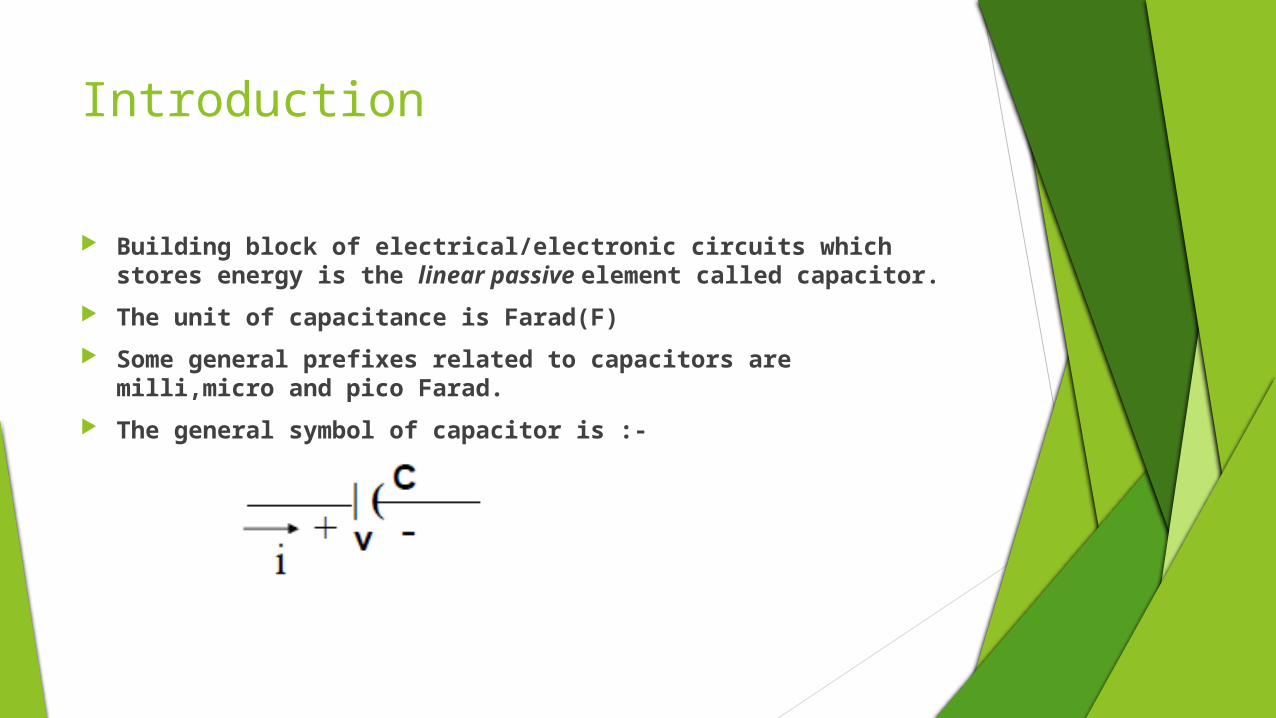
Introduction
Building block of electrical/electronic circuits which stores energy is the linear passive element called capacitor.
The unit of capacitance is Farad(F)
Some general prefixes related to capacitors are milli,micro and pico Farad.
The general symbol of capacitor is :-

Properties
The charge accumulated on capacitor is given by :-
Q=CV
‘C’ is not dependent on ‘q’ or ‘v’ but on the physical dimensions of capacitor.
Where ε= permittivity of material
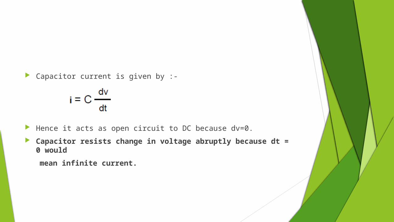
Capacitor current is given by :-
Hence it acts as open circuit to DC because dv=0.
Capacitor resists change in voltage abruptly because dt = 0 would
mean infinite current.
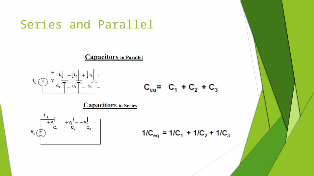
Series and Parallel
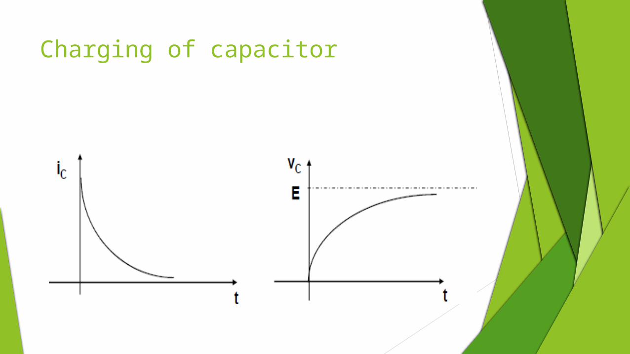
Charging of capacitor

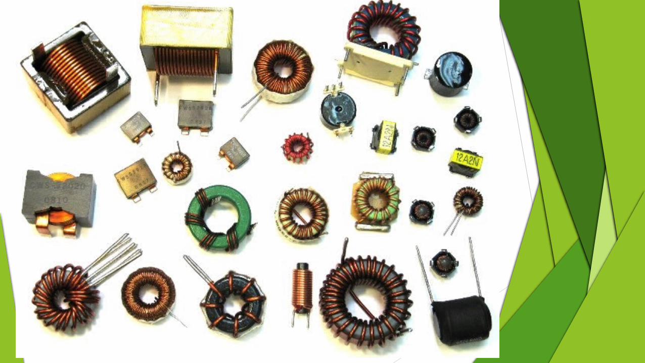
Inductors
Introduction An inductor is a coil of wire having magnetic properties.
Is a passive two terminal electric component which resists changes in electric current passing through it.
It consists of a conductor such as a wire, usually wound into a coil. When a current flows through it, energy is stored temporarily in a magnetic field in the coil.
Whenever current passes through a conductor, lines of magnetic flux are generated around it. This magnetic flux opposes any change in current due to the induced e.m.f.
This opposition to the current is known as inductance and the component producing inductance is known as inductor.
Relationship
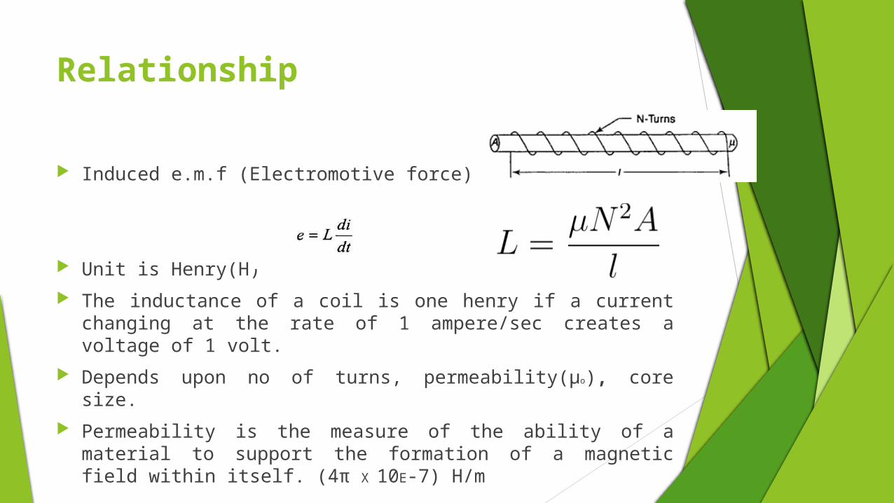
Induced e.m.f (Electromotive force)
Unit is Henry(H)
The inductance of a coil is one henry if a current changing at the rate of 1 ampere/sec creates a voltage of 1 volt.
Depends upon no of turns, permeability(µo), core size.
Permeability is the measure of the ability of a material to support the formation of a magnetic field within itself. (4π X
10E-7) H/m
Ideal and non ideal behaviour
An "ideal inductor" has inductance, but no resistance or capacitance, and does not dissipate or radiate energy.
However real inductors have resistance and parasitic capacitance (due to the electric field between the turns of wire which are at slightly different potentials).
At high frequencies the capacitance begins to affect the inductor's behaviour.
Inductors with ferromagnetic cores have additional energy losses due to hysteresis and eddy currents in the core
At high currents, iron core inductors also show gradual departure from ideal behaviour due to nonlinearity caused by magnetic saturation of the core.
An inductor may radiate electromagnetic energy into surrounding space and circuits, and may absorb electromagnetic emissions from other circuits.

Current and voltage
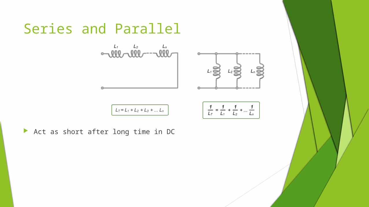
Series and Parallel
Act as short after long time in DC

Applications
Transformers
switched-mode power supplies to produce DC current
particularly in radio equipment.
They are used to block the flow of AC current while allowing DC to pass; inductors designed for this purpose are called chokes.
They are also used in electronic filters to separate signals of different frequencies, and in combination with capacitors to make tuned circuits, used to tune radio and TV receivers.
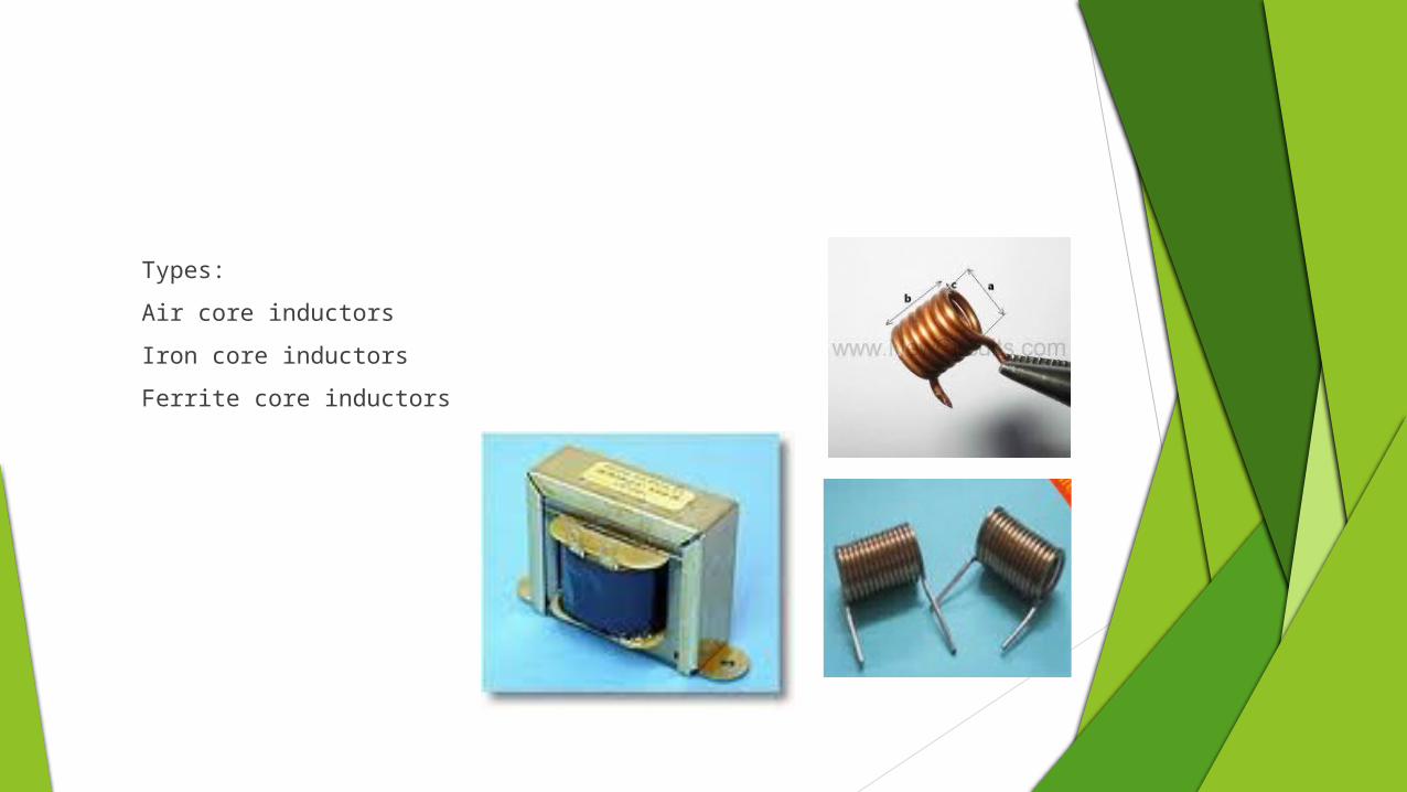
Types:
Air core inductors
Iron core inductors
Ferrite core inductors