Garage Door Repair Edmonton | Garage Door Installation | Garage Door Opener Replacement Service

CONTENTSPreparation . . . . . . . . . . . . . . . .2-3Assembly . . . . . . . . . . . . . . . . .4-5Installation . . . . . . . . . . . . . . . 6-13Install the Door Control . . . . . . 14-16Install the Protector System® . . 17-20Power. . . . . . . . . . . . . . . . . . 21-22Adjustments . . . . . . . . . . . . . 23-25Operation . . . . . . . . . . . . . . . . . 26Features . . . . . . . . . . . . . . . . . . 27Door Control . . . . . . . . . . . . . 28-29Remote Control . . . . . . . . . . . 30-31To Erase the Memory . . . . . . . . . 31To Open the Door Manually . . . . . 32Maintenance . . . . . . . . . . . . . . . 32Troubleshooting. . . . . . . . . . . 33-34Accessories. . . . . . . . . . . . . . . . 35Warranty. . . . . . . . . . . . . . . . . . 36Repair Parts . . . . . . . . . . . . . 37-38Notes . . . . . . . . . . . . . . . . . . . . 39
PREMIUM SeriesBelt Drive Garage Door Opener
■ Please read this manual and the enclosed safety materials carefully!
■ Fasten the manual near the garage door after installation.
■ The door WILL NOT CLOSE unless the Protector System® is connected and properly aligned.
■ Periodic checks of the garage door opener are required to ensure safe operation.
■ The model number label is located on the front panel of your garage door opener.
■ This garage door opener is ONLY compatible with MyQ® and Security✚ 2.0™ accessories.
■ ONLY enable the Timer-to-Close* or MyQ® remote operation feature* when the garage door opener is installed on a sectional door. (*Not available on all models)
NOTE: If you are installing the garage door opener on a one-piece door, visit www.liftmaster.com for installation instructions.
www.raynor.comSerial Number:
Date of Purchase:
Model 8355RGD - 1/2 hp
FOR RESIDENTIAL USE ONLY
Write down the following information for future reference:
.
Raynor Garage Doors1101 E. River Rd.
Dixon, Illinois 61021

2
Safety Symbol and SignalWord ReviewThis garage door opener has been designed andtested to offer safe service provided it is installed,operated,maintained and tested in strictaccordance with the instructions and warningscontained in thismanual.When you see these Safety Symbols and SignalWords on the following pages, they will alert youto the possibility of serious injury or death if youdo not comply with the warnings that accompanythem. The hazard may come from somethingmechanical or from electric shock. Read thewarnings carefully.
Mechanical
ElectricalWhen you see this Signal Word on the followingpages, it will alert you to the possibility of damageto your garage door and/or the garage dooropener if you do not comply with the cautionarystatements that accompany it. Read themcarefully.
Check the Door1. Disable locks and remove any ropes
connected to the garage door.2. Lift the door halfway up. Release the
door. If balanced, it should stay inplace, supported entirely by its springs.
3. Raise and lower the door to check forbinding or sticking. If your door binds,sticks, or is out of balance, call a traineddoor systems technician.
4. Check the seal on the bottom of thedoor. Any gap between the floor andthe bottom of the door must not exceed1/4 inch (6 mm).Otherwise, the safetyreversal systemmay not work properly.
5. The opener should be installed abovethe center of the door. If there is atorsion spring or center bearing platein the way of the header bracket, it maybe installed within 4 feet (1.2 m) to theleft or right of the door center. Seepage 7.
Torsion Spring Extension SpringOR
To prevent possible SERIOUS INJURY orDEATH:• ALWAYS call a trained door systems
technician if garage door binds, sticks, or isout of balance. An unbalanced garagedoor mayNOT reverse when required.
• NEVER try to loosen,move or adjustgarage door, door springs, cables, pulleys,brackets or their hardware, ALL of whichare under EXTREME tension.
• Disable ALL locks and remove ALL ropesconnected to garage door BEFOREinstallation and operating garage dooropener to avoid entanglement.
To prevent damage to garage door andopener:• ALWAYS disable locks BEFORE installing
and operating the opener.• ONLY operate garage door opener at
120 V, 60 Hz to avoid malfunction anddamage.
Tools Needed
21
3/16
7/16
1/2
5/32
5/16
5/8
9/16
1/4
7/16
Preparation

3
A B
C
J
N
I
OP
DE
F
H
GK
L
M
Carton Inventory
A. tekcarb redaeH
B. Pulley and bracket
C. tekcarb rooD
D. mra rood devruC
E. mra rood thgiartS
F. yellorT
G. Emergency release rope and handle
H. Rail
I. renepo rood egaraG
NOTE: Accessories will vary depending on the garage door opener model purchased. Depending on your specific model, other accessories may be included with your garage door opener. The instructions for these accessories will be attached to the accessory and are not included in this manual. The images throughout this manual are for reference and your product may look different.
J.K. tleB
L. lortnoc rooD
M. eriw etihw/der dna etihW
N.srosnes gnisrever ytefaS
with white and white/black wire attached: Sending Sensor (1) Receiving Sensor (1)
and Safety Sensor Brackets (2)
O. erutaretil dna slebal ytefaS
P. Rail grease
Not Provided
Not Provided
HardwareInstallation
Hex Bolt 5/16"-18 x 7/8" (4)
Lag Screw 5/16"-9 x 1-5/8" (2)
Clevis Pin 5/16" x 2-3/4" (1)
Clevis Pin 5/16" x 1-1/4" (1)
Clevis Pin 5/16" x 1" (1)
Nut 5/16"-18 (4)
Lock Washer 5/16" (4)
Self-Threading Screw 1/4"-14 x 5/8" (2)
Ring Fastener (3)
Carriage Bolt 1/4"-20 x 1/2" (2)
Wing Nut 1/4"-20 (2)
Door Control Hardware
Screw 6AB x 1" (2)
Screw 6-32 x 1" (2)
Drywall Anchors (2)
Insulated Staples
The Protector System®
Sprocket cover with hex screws
SECURITY✚ 2.0TM ACCESSORIES
893RGXRemote Control
041A7185-2Multi-Function
Door Control
Preparation

4
To avoid possible SERIOUS INJURY to finger frommoving garage door opener:• ALWAYS keep hand clear of sprocket while
operating opener.• Securely attach sprocket cover BEFORE
operating.
To avoid SERIOUS damage to garage dooropener, use ONLY those bolts/fastenersmounted in the top of the opener.
Washered Bolt5/16"-18x1/2"(Mounted in the garage door opener)
HARDWARE
Hex Screw#8x3/8"(Packed with the sprocket cover)
Lock Nut(Mounted in the garage door opener)
NOTE: ONLY use the bolts removed from thegarage door opener. Place the garage dooropener on the packing material to preventscratching.1.1 Remove bolt and lock nut from the top
of the garage door opener.
1.2 Align the rail and the styrofoam over thesprocket. Cut the tape from the rail, belt,and styrofoam.
1.3 Fasten the rail with the previouslyremoved washered bolt and lock nut.
1.4 Position the belt around the garagedoor opener sprocket.
1.5 Attach the sprocket cover over thegarage door opener sprocket andattach with hex screws.
Hex Screw
#8x3/8"Washered Bolt
5/16"-18x1/2" Lock
Nut
Assembly1 Attach the rail to the garage door opener

5
2 Tighten the Belt2.1 By hand, thread the spring trolley nut on the threaded shaft until it is finger tight against
the trolley. Do not use any tools.
Spring Trolley Nut
(To motor unit)
2.2 Insert a flathead screwdriver tip into one of the nut ring slots and brace it firmly against the trolley.
Nut ring
slot
2.3 Tighten the spring trolley nut with an adjustable wrench or a 7/16" open end wrench about a quarter turn until the spring releases and snaps the nut ring against the trolley. This sets the spring tooptimum belt tension.
Nut Ring Nut Ring
AFTER RELEASE1-1/4"
(3.18 cm)
BEFORE1"
(2.5 cm)

6
IMPORTANT INSTALLATION INSTRUCTIONSWARNING
To reduce the risk of SEVERE INJURY or DEATH:1. READANDFOLLOWALL INSTALLATIONWARNINGS AND INSTRUCTIONS.2. Install garage door opener ONLY on properly balanced and lubricated garage door. An
improperly balanced door mayNOT reverse when required and could result in SEVEREINJURY or DEATH.
3. ALL repairs to cables, spring assemblies and other hardware MUST be made by a traineddoor systems technician BEFORE installing opener.
4. Disable ALL locks and remove ALL ropes connected to garage door BEFORE installingopener to avoid entanglement.
5. Install garage door opener 7 feet (2.13 m) or more above floor.6. Mount the emergency release within reach, but at least 6 feet (1.83 m) above the floor and
avoiding contact with vehicles to avoid accidental release.7. NEVER connect garage door opener to power source until instructed to do so.8. NEVER wear watches, rings or loose clothing while installing or servicing opener. They could
be caught in garage door or opener mechanisms.
9. Install wall-mounted garage door control:
• within sight of the garage door.• out of reach of children atminimum height of 5 feet (1.5 m).• away fromALL moving parts of the door.
10. Place entrapment warning label on wall next to garage door control.11. Place manual release/safety reverse test label in plain view on inside of garage door.12. Upon completion of installation, test safety reversal system. Door MUST reverse on contact with
a 1-1/2" (3.8 cm) high object (or a 2x4 laid flat) on the floor.13. To avoid SERIOUS PERSONAL INJURY or DEATH from electrocution, disconnect ALL
electric and battery power BEFORE performing ANY service or maintenance.14. DO NOT enable the Timer-to-Close functionality if operating either one-piece or swinging
garage doors. To be enabled ONLY when operating a sectional door.
NOTE: If you are installing the garage door opener on a one-piece door, visit www.raynor.com for installation instructions.
Installation

7
To prevent possible SERIOUS INJURY orDEATH:• Header bracketMUST be RIGIDLY
fastened to structural support on headerwall or ceiling, otherwise garage door mightNOT reverse when required. DO NOTinstall header bracket over drywall.
• Concrete anchorsMUST be used ifmounting header bracket or 2x4 intomasonry.
• NEVER try to loosen,move or adjustgarage door, springs, cables, pulleys,brackets, or their hardware, ALL of whichare under EXTREME tension.
• ALWAYS call a trained door systemstechnician if garage door binds, sticks, or isout of balance. An unbalanced garagedoor might NOT reverse when required.
• DO NOT enable the Timer-to-Closefunctionality if operating either one-piece orswinging garage doors. To be enabledONLY when operating a sectional door.
1 Determine the header bracket location
NOTE: If you are installing the garage door opener on a one-piece door, visit www.raynor.com forinstallation instructions.1.1 Close the door and mark the inside vertical centerline of the garage door.1.2 Extend the line onto the header wall above the door.
You can fasten the header bracket within 4 feet (1.22 m) of the left or right of the doorcenter only if a torsion spring or center bearing plate is in the way; or you can attach it tothe ceilingwhen clearance is minimal. (It may be mounted on the wall upside down ifnecessary, to gain approximately 1/2" (1 cm).If you need to install the header bracket on a 2x4 (on wall or ceiling), use lag screws (notprovided) to securely fasten the 2x4 to structural supports.
1.3 Open your door to the highest point of travel as shown. Draw an intersecting horizontal line onthe header wall 2" (5 cm) above the high point. This height will provide travel clearance for thetop edge of the door.
NOTE: If the total number of inches exceeds the height available in your garage, use the maximumheight possible, or refer to page 8 for ceiling installation.
Sectional door with curved track
Header Wall
Track
2" (5 cm)
Highest Point of Travel
Door
Header Wall
Unfinished
Ceiling
Vertical Centerline of Garage Door
2x4
2x4
Structural Supports
Level (Optional)
OPTIONAL CEILING MOUNT FOR HEADER BRACKET
8
You can attach the header bracket either to thewall above the garage door, or to the ceiling.Follow the instructions which will work best foryour particular requirements.Donot install theheader bracket over drywall. If installing intomasonry, use concrete anchors (not provided).
HARDWARE
Lag Screw5/16" - 9 x 1-5/8"
OPTION A WALL INSTALLATION2.1A Center the bracket on the vertical
centerline with the bottom edge of thebracket on the horizontal line as shown(with the arrow pointing toward theceiling).
2.2A Mark the vertical set of bracket holes (donot use the holes designated for ceilingmount). Drill 3/16" pilot holes and fastenthe bracket securely to a structuralsupport with lag screws.
OPTION B CEILING INSTALLATION2.1B Extend the vertical centerline onto the
ceiling as shown.2.2B Center the bracket on the vertical mark,
no more than 6" (15 cm) from the wall.Make sure the arrow is pointing towardthe wall. The bracket can be mountedflush against the ceiling when clearanceisminimal.
2.3B Mark the side holes. Drill 3/16" pilot holesand fasten bracket securely to a structuralsupport with lag screws.
Wall Mount
Optional Mounting Holes
Vertical Centerline of Garage Door
(Header Wall)
Header Bracket
2x4 Structural Support
Door Spring
(Garage Door)
Highest Point of Garage Door Travel
Horizontal Line
Lag Screw5/16" - 9 x 1-5/8"
(Header Wall)
Ceiling Mounting Holes
(Finished Ceiling)
Vertical Centerline of Garage Door
Header Bracket
6" (15 cm) Maximum
Door Spring
(Garage Door)
Lag Screw5/16" - 9 x 1-5/8"
Installation2 Install the Header Bracket

9
3.1 Align the rail with the header bracket.Insert the clevis pin through the holes inthe header bracket and rail. Securewith the ring fastener.
NOTE: Use the packing material as aprotective base for the garage door opener.
RingFastener
Clevis Pin5/16" X 2-3/4"
HARDWARE
Clevis Pin5/16" x 2-3/4"
Ring Fastener
4 Position the garage door opener
To prevent damage to garage door, rest garagedoor opener rail on 2x4 placed on top section ofdoor.
4.1 Remove the packing material and lift thegarage door opener onto a ladder.
NOTE: A 2x4 is ideal for setting the distancebetween the rail and the door. If the ladder isnot tall enough you will need help at this point.
4.2 Fully open the door and place a 2x4 (laid flat) under the rail.NOTE: If the door hits the trolley when it is raised, pull the trolley release arm down todisconnect the inner and outer trolley. Slide the outer trolley toward the garage door opener.The trolley can remain disconnected until instructed.
Connected Disconnected
3 Attach the rail to the header bracket

10
5 Hang the garage door opener
To avoid possible SERIOUS INJURY from a fallinggarage door opener, fasten it SECURELY tostructural supports of the garage. Concrete anchorsMUST be used if installing ANY brackets intomasonry.
HARDWARE
Hex Bolt 5/16"- 18x7/8"
Nut 5/16"-18
Lock Washer
5/16"
Installation
Hanging your garage door opener will vary depending on yourgarage. Two representative installations are shown. Yoursmaybe different. Hanging brackets should be angled (Figure 1) toprovide rigid support. On finished ceilings (Figure 2), attach asturdymetal bracket to structural supports before installing theopener. This bracket and fastening hardware are not provided.Instructions below are for attaching the garage door openerdirectly to structural supports.5.1 Measure the distance from each side of the motor unit to
the structural support.5.2 Cut both pieces of the hanging bracket to required lengths.5.3 Drill 3/16" pilot holes in the structural supports.5.4 Attach one end of each bracket to a support with 5/16"-
18x1-7/8" lag screws (not provided).5.5 Fasten the opener to the hanging brackets with 5/16"-
18x7/8" hex bolts, lock washers and nuts.5.6 Check to make sure the rail is centered over the door (or in
line with the header bracket if the bracket is not centeredabove the door).
5.7 Remove the 2x4. Operate the door manually. If the doorhits the rail, raise the header bracket.
NOTE: DO NOT connect power to opener at this time.
FIGURE 1 FIGURE 2
(Not Provided)
Lag Screws
5/16"- 18x1-7/8"
Measure
Distance
Hex Bolt 5/16"- 18x7/8", Lock Washer 5/16", Nut 5/16"-18
FIGURE 3
Not Provided
Finished CeilingUnfinished Ceiling

11
To prevent possible OVERHEATING of the end panel or light socket:• Use ONLY A19 incandescent (100W maximum) or compact fluorescent (26W maximum) light
bulbs.• DO NOT use incandescent bulbs larger than 100W.• DO NOT use compact fluorescent light bulbs larger than 26W (100W equivalent).To prevent damage to the opener:• DO NOT use halogen bulbs.• DO NOT use short neck or specialty light bulbs.
6.1 Pull on the top center of the light lens and rotate thelight lens down.
6.2 Insert an A19 incandescent (100Wmaximum) orcompact fluorescent (26W, 100W equivalent) lightbulb into the light socket.
NOTE: Do not use halogen, short neck, or specialty lightbulbs as these may overheat the end panel or light socket.Do not use LED bulbs as theymay reduce the range orperformance of your remote control(s).6.3 Rotate the lens up to close.
or or
7 Attach the emergency release rope and handle
To prevent possible SERIOUS INJURY or DEATH from a falling garage door:• If possible, use emergency release handle to disengage trolleyONLY when garage door is
CLOSED.Weak or broken springs or unbalanced door could result in an open door fallingrapidly and/or unexpectedly.
• NEVER use emergency release handle unless garage doorway is clear of persons andobstructions.
• NEVER use handle to pull door open or closed. If rope knot becomes untied, you could fall.
7.1 Insert one end of the emergency release ropethrough the handle.Make sure that “NOTICE” isright side up. Tie a knot at least 1 inch (2.5 cm) fromthe end of the emergency release rope.
7.2 Insert the other end of the emergency release ropethrough the hole in the trolley release arm.Mountthe emergency release within reach, but at least 6feet (1.83 m) above the floor, avoiding contact withvehicles to prevent accidental release and securewith a knot.
NOTE: If it is necessary to cut the emergency release rope,seal the cut end with a match or lighter to preventunraveling. Ensure the emergency release rope andhandle are above the top of all vehicles to avoidentanglement.
Trolley
Release Arm
6 Install the light bulbs

12
Fiberglass, aluminum or lightweight steel garage doorsWILL REQUIRE reinforcement BEFOREinstallation of door bracket. Contact your door manufacturer for reinforcement kit.
Figure 1 shows one piece of angle iron as the horizontal brace.For the vertical brace, 2 pieces of angle iron are used to create aU-shaped support. The best solution is to check with your garagedoor manufacturer for an opener installation door reinforcementkit.NOTE: Many door reinforcement kits provide for direct attachmentof the clevis pin and door arm. In this case you will not need thedoor bracket; proceed to the next step.
Self-Threading Screw1/4"-14x5/8"
HARDWARE
SECTIONAL DOORS8.1 Center the door bracket on the previouslymarked vertical centerline used for the header bracket
installation. Note correct UP placement, as stamped inside the bracket.8.2 Position the top edge of the bracket 2"-4" (5-10 cm) below the top edge of the door, OR directly below
any structural support across the top of the door.8.3 Mark, drill holes and install as follows, depending on your door’s construction:
Metal or light weight doors using a vertical angle iron brace between the door panel supportand the door bracket:• Drill 3/16" fastening holes. Secure the door bracket using the two self threading screws.(Figure 2)
• Alternately, use two 5/16" bolts, lock washers and nuts (not provided). (Figure 3)Metal, insulated or light weight factory reinforced doors:• Drill 3/16" fastening holes. Secure the door bracket using the self-threading screws. (Figure 4)WoodDoors:• Use top and bottom or side to side door bracket holes. Drill 5/16” holes through the door andsecure bracket with 5/16"-18x2" carriage bolts, lock washers and nuts (not provided). (Figure 5)
NOTE: The 1/4"-14x5/8" self-threading screws are not intended for use on wood doors.
8 Install the door bracket A horizontal and vertical reinforcementis needed for lightweight garage doors(fi berglass, aluminum, steel, doorswith glass panel, etc.) (not provided).
A horizontal reinforcement braceshould be long enough to be securedto two or three vertical supports.A vertical reinforcement brace shouldcover the height of the top panel.
FIGURE 1
FIGURE 2
FIGURE 4 FIGURE 5
FIGURE 3
Vertical Reinforcement
Vertical Centerline
of Garage Door
UP
Door Bracket
Self-Threading Screw
1/4" - 14x 5/8"
Self-Threading
Screw
1/4" - 14x 5/8"
Vertical Reinforcement
Bolt 5/16"-18x2"
(Not provided)
Lock Washer 5/16"
Nut 5/16"-18
Door Bracket
UP
Vertical Centerline
of Garage Door
UP
Vertical
Centerline of
Garage Door
Bolt 5/16"-18x2"
(Not provided)
UP
Inside Edge of Door or
Reinforcement Board
Vertical Centerline
of Garage Door
Installation

13
IMPORTANT: The groove on the straight door armMUST face away from the curved door arm.
Straight Door Arm Curved
DoorArm
(Groove facing out)
CORRECT
INCORRECT
Straight Door Arm Curved
Door Arm
9.1 Close the door. Disconnect the trolley bypulling the emergency release handle.Slide the outer trolley back (away fromthe door) about 2" (5 cm).
9.2 Attach the straight door arm to the outertrolley using the clevis pin. Attach withthe ring fastener.
Ring
Fastener
Clevis Pin
5/16" x 1"
9.3 Attach the curved door arm to the doorbracket using the clevis pin. Attach withthe ring fastener.
Ring
Fastener
Clevis Pin
5/16" x 1-1/4"
HARDWARE
Hex Bolt 5/16"-18x7/8"
Nut
5/16"-18
Lock
Washer5/16"
Clevis Pin
5/16"x1"
Clevis Pin 5/16"x1-1/4"
Ring Fastener
9.4 Align the straight door armwith thecurved door arm. Select two alignedholes (as far apart as possible) andattach using the bolts, nuts and lockwashers.
Nut 5/16" - 18
Lock
Washer
5/16"
Hex Bolt
5/16" - 18 x 7/8"
NOTE: If the holes do not line up, reverse thestraight door arm. Select two aligned holes (asfar apart as possible) and attach using thebolts, nuts and lock washers.
If the straight door arm is hanging down too far, you may cut 6 inches (15 cm) from the solid end.
Nut 5/16" - 18
Lock Washer5/16"
Hex Bolt 5/16" - 18 x 7/8"
9.5 Pull the emergency release handletoward the garage door opener until thetrolley release arm is horizontal. Thetrolley will re-engage automatically whenthe garage door opener is activated.
Trolley release arm
9 Connect the door arm to the trolley

14
1 Install the door control
Install the Door Control
To prevent possible SERIOUS INJURY or DEATH from electrocution:• Be sure power is NOT connected BEFORE installing door control.• Connect ONLY to 12 VOLT low voltage wires.To prevent possible SERIOUS INJURY or DEATH from a closing garage door:• Install door control within sight of garage door, out of reach of children at a minimum height of 5 feet
(1.5 m), and away fromALL moving parts of door.• NEVER permit children to operate or play with door control push buttons or remote control
transmitters.• Activate door ONLY when it can be seen clearly, is properly adjusted, and there are no
obstructions to door travel.• ALWAYS keep garage door in sight until completely closed. NEVER permit anyone to cross path of
closing garage door.
INTRODUCTIONCompatible with MyQ® and Security+ 2.0™accessories, see page 35. Your garage dooropener is compatible with up to 2 Smart ControlPanels or 4 of any other Security+ 2.0™ doorcontrols.NOTE: Older Raynor door controls andthird party products are not compatible.
Install the door control within sight of the door ata minimum height of 5 feet (1.5 m) where smallchildren cannot reach, and away from themoving parts of the door.NOTE: Your productmay look different thanmoving parts of the door the illustrations.
Screw6ABx1"
HARDWARE
Drywall Anchors Screw
6-32x1"
NOTE: For gang box installations it is not necessary to drill holes or install the drywall anchors. Use the existing holes in the gang box.
1.1 Strip 7/16 inch (11 mm) of insulation fromone end of the wire and separate the wires.
7/16" (11 mm)
1.2 Connect one wire to each of the two screwson the back of the door control. The wirescan be connected to either screw.PRE-WIRED INSTALLATIONS: Chooseany two wires to connect, note which wiresare used so the correct wires are connectedat the garage door opener in a later step.
1.3 Mark the location of the bottommountinghole and drill a 5/32 inch (4 mm) hole.
Wall
1.4 Install the bottom screw, allowing 1/8 inch(3 mm) to protrude from the wall.
Screw
6-32 x 1"
DRYWALLGANG BOX
Screw
6AB x 1"
Drywall Anchor

15
k
Install the Door Control
1.5 Position the bottom hole of the doorcontrol over the screw and slidedown into place.
1.6 Lift the push bar up and mark the top hole. 1.7 Remove the door control from the walland drill a 5/32 inch (4 mm) hole forthe top screw.
1.8 Position the bottom hole of thedoor control over the screw andslide down into place. Attach thetop screw.
DRYWALL
Drywall Anchor
Screw 6-32 x 1"
Screw 6AB x 1"
GANG BOX
2 Wire the door control to the garage door opener
HARDWARE
Insulated Staple(Not shown)
PRE-WIRED INSTALLATIONS:When wiringthe door control to the garage door openermake sure you use the same wires that areconnected to the door control.
2.1 Run the white and red/white wire from the door control tothe garage door opener. Attach the wire to the wall andceiling with the staples (not applicable for gang box orpre-wired installations). Do not pierce the wire with thestaple as thismay cause a short or an open circuit.
Staple
2.2 Strip 7/16 inch (11 mm) of insulationfrom the end of the wire near thegarage door opener.
7/16" (11 mm)
2.3 Connect the wire to the red andwhite terminals on the garagedoor opener. To insert orrelease wires from the terminal,push in the tab with screwdrivertip.
RE
D
WH
ITE
WH
ITE
GR
EY
WH
IW
HIT
EE

16
Install the Door Control
3 Attach the warning labels3.1 Attach the entrapment warning label on the wall near the door control with tacks or
staples.3.2 Attach the manual release/safety reverse test label in a visible location on the inside of
the garage door.

17
Introduction
Be sure power is NOT connected to the garagedoor opener BEFORE installing the safetyreversing sensor.To prevent SERIOUS INJURY or DEATH fromclosing garage door:• Correctly connect and align the safety
reversing sensor. This required safetydevice MUSTNOT be disabled.
• Install the safety reversing sensor so beamis NO HIGHER than 6" (15 cm) abovegarage floor.
Install the Protector System®
IMPORTANT INFORMATION ABOUT THE SAFETY REVERSING SENSORSThe safety reversing sensors must be connected and aligned correctly before the garage door openerwillmove in the down direction.The sending sensor (with an amber LED) transmits an invisible light beam to the receiving sensor (with a green LED). If an obstruction breaks the lightbeamwhile the door is closing, the door will stop and reverse to the full open position, and the garage door opener lights will flash 10 times.NOTE: For energy efficiency the garage door opener will enter sleep mode when the door is fully closed. The sleep mode shuts the garage dooropener down until activated. The sleep mode is sequenced with the garage door opener light bulb; as the light bulb turns off the sensor LEDswill turnoff and whenever the garage door opener lights turn on the sensor LEDswill light. The garage door opener will not go into the sleep mode until thegarage door opener has completed 5 cycles upon power up.When installing the safety reversing sensors check the following:• Sensors are installed inside the garage, one on either side of the door.• Sensors are facing each other with the lenses aligned and the receiving sensor lens does not receive direct sunlight.• Sensors are no more than 6 inches (15 cm) above the floor and the light beam is unobstructed.
Invisible Light BeamProtection Area
Safety Reversing Sensor6" (15 cm) max. above floor
Safety Reversing Sensor6" (15 cm) max. above floor

Install the Protector System®
1 Install the Safety Reversing SensorsThe safety reversing sensors can be attached to the door track, the wall, or the floor. If the door track will not support the sensor bracket a wall installation is recommended. Choose one of the following installations.
HARDWARE
Carriage Bolt1/4"-20x1/2"
Wing Nut1/4"-20
OPTION A DOOR TRACK INSTALLATION
1.1A Slide the curved arms of the sensorbracket around the edge of the doortrack. Snap into place so that thesensor bracket is flush against thetrack.
1.2A Slide the carriage bolt into the slot oneach sensor.
Carriage Bolt
1/4" - 20 x 1/2"
1.3A Insert the bolt through the hole in the sensorbracket and attach with the wing nut. The lenseson both sensors should point toward each other.Make sure the lens is not obstructed by thesensor bracket.
Wing Nut1/4" - 20
OPTION B WALL INSTALLATIONIf additional clearance is needed an extension bracket (not provided) or wood blocks can be used.Make sure each bracket has the same amount of clearance so they will align correctly.
1.1B Position the sensor bracket against thewall with the curved arms facing thedoor.Make sure there is enoughclearance for the beam to beunobstructed.Mark holes.
(not provided)
1.2B Drill 3/16 inch pilot holes for each sensorbracket and attach the sensor bracketsto the wall using lag screws (notprovided).
Inside
Garag
e
Wall
(not provided)
1.3B Slide the carriage bolt into the slot oneach sensor.
Lens
Carriage Bolt
1/4" - 20 x 1/2"
1.4B Insert the bolt through the hole in the sensorbracket and attach with the wing nut. The lenseson both sensors should point toward eachother. Make sure the lens is not obstructed bythe sensor bracket.
Wing Nut
1/4" - 20
18

Install the Protector System®
1 Install the Safety Reversing SensorsOPTION C FLOOR INSTALLATIONUse an extension bracket (not provided) or wood block to raise the sensor bracket if needed.
1.1C Carefully measure the position of bothsensor brackets so they will be the samedistance from the wall and unobstructed.
1.2C Attach the sensor brackets to the floorusing concrete anchors (notprovided).
Inside
Garage
Wall
(not provided)
1.3C Slide the carriage bolt into the slot oneach sensor.
Carriage Bolt
1/4" - 20 x 1/2"
1.4C Insert the bolt through the hole in the sensorbracket and attach with the wing nut. The lenson both sensors should point toward eachother. Make sure the lens is not obstructed bythe sensor bracket.
Wing Nut
1/4" - 20
2 Wire the Safety ReversingSensors OPTION A INSTALLATION WITHOUT PRE-WIRING
PRE-WIRED INSTALLATIONS: If your garagealready haswires installed for the safety reversingsensors, see page 20.
HARDWARE
Insulated Staple(Not shown)
2.1A Run the wire from both sensors to thegarage door opener. Attach the wire tothe wall and ceiling with the staples.
Staple
2.2A Strip 7/16 inch (11 mm) of insulationfrom each set of wires. Separate thewires. Twist the white wires together.Twist the white/black wires together.
7/16" (11 mm)
2.3A Insert the white wires into the white terminal onthe garage door opener. Insert the white/blackwires into the grey terminal on the garage dooropener. To insert or remove the wires from theterminal, push in the tab with a screwdriver tip.
RE
D
WH
ITE
WH
ITE
GR
EY
DR
ED
WRE
WH
ITE
WH
ITE
GR
EY
GR
EY
19

Install the Protector System®
OPTION B PRE-WIRED INSTALLATION
2.1B Cut the end of the safetyreversing sensor wire,makingsure there is enough wire toreach the pre-installed wiresfrom the wall.
2.2B Separate the safety reversing sensor wires and strip 7/16 inch (11 mm) ofinsulation from each end. Choose two of the pre-installed wires and strip 7/16inch (11 mm) of insulation from each end.Make sure that you choose thesame color pre-installed wires for each sensor.
7/16" (11 mm)
7/16" (11 mm)
Safety reversing sensor wires
Pre-installed wires
2.3B Connect the pre-installed wires to the sensor wires with wire nutsmaking sure the colors correspond for each sensor. For example,the white wire would connect to the yellowwire and the white/blackwire would connect to the purple wire.
White
White/Black
Yellow (for example)
Purple (for example)
Not Provided
Pre-installed wires
Safety reversing sensor wires
2.4B At the garage door opener, strip 7/16 inch (11 mm) of insulation from each end of the wires previously chosen for thesafety reversing sensors. Twist the like-colored wires together.
7/16" (11 mm)
Yellow
Purple
2.5B Insert the wires connected to the white safety sensor wires to thewhite terminal on the garage door opener. Insert the wires that areconnected to the white/black safety sensor wires to the greyterminal on the garage door opener.
RE
D
WH
ITE
WH
ITE
GR
EY
D
WRE
DR
E
Purple(for example)
Yellow(for example)
To insert or remove the wires from the terminal, push in the tab with a screwdriver tip.
WH
ITE
WH
ITE
GR
EY
GR
EY
20

21
1 Connect Power
To prevent possible SERIOUS INJURY orDEATH from electrocution or fire:• Be sure power is NOT connected to the
opener, and disconnect power to circuitBEFORE removing cover to establishpermanent wiring connection.
• Garage door installation and wiring MUSTbe in compliance with ALL local electricaland building codes.
• NEVER use an extension cord, 2-wireadapter, or change plug in anyway to makeit fit outlet. Be sure the opener is grounded.
To avoid installation difficulties, do not activate the garage door opener at this time.To reduce the risk of electric shock, your garage door opener has a grounding type plug with a thirdgrounding pin. This plug will only fit into a grounding type outlet. If the plug doesn’t fit into your outlet,contact a qualified electrician to install the proper outlet.
THERE ARE TWO OPTIONS FOR CONNECTING POWER:
OPTION A TYPICAL WIRING1.1A Plug in the garage door opener into a grounded outlet.1.2A DO NOT run garage door opener at this time.
TYPICAL WIRING
Ground Tab
Green
Ground
Screw
Ground
Wire
White Wire
PERMANENT WIRING
Black Wire
Black Wire
OPTION B PERMANENT WIRINGIf permanent wiring is required by your local code, refer to the following procedure.Tomake a permanent connection through the 7/8 inch hole in the top of the motor unit (according tolocal code):1.1B Remove the motor unit cover screws and set the cover aside.1.2B Remove the attached 3-prong cord.1.3B Connect the black (line) wire to the screw on the brass terminal; the white (neutral) wire to the
screw on the silver terminal; and the ground wire to the green ground screw.The openermustbe grounded.
1.4B Reinstall the cover.
Power

22
2 Ensure the Safety Reversing Sensors are alignedThe doorwill not close if the sensorshave not been installed and alignedcorrectly.
When the light beam is obstructed ormisaligned while the door is closing, thedoor will reverse and the garage dooropener lights will flash ten times. If the dooris already open, it will not close. Thesensors can be aligned by loosening thewing nuts, aligning the sensors, andtightening the wing nuts.
2.1 Check to make sure the LEDs in both sensors are glowing steadily. The LEDs in both sensors will glow steadily if theyare aligned and wired correctly.
Green LED
ROSNES GNIVIECERROSNES GNIDNES
Amber LED
If the receiving sensor is in direct sunlight, switch it with sending sensor so it is on the opposite side of the door.
(invisible light beam)
IF THE AMBERLEDONTHE SENDING SENSOR IS NOTGLOWING: IF THE GREENLEDONTHE RECEIVING SENSOR IS NOTGLOWING:Make sure there is power to the garage door opener.
Make sure the sensor wire is not shorted/broken.
RED
WH
ITE
WH
ITE
GR
EY
Make sure the sensor has been wired correctly: white wires to white terminal and white/black wires to grey terminal.
Make sure the sensors are aligned.Make sure the sensor wire is not shorted/broken.
3 Ensure the Door Control is wired correctlyIf the door control has been installed and wired correctly, the command LED behind the push bar will blink.
Power

23
Without a properly installed safety reversalsystem, persons (particularly small children)could be SERIOUSLY INJURED or KILLED by aclosing garage door.• Incorrect adjustment of garage door travel
limits will interfere with proper operation ofsafety reversal system.
• After ANY adjustments are made, the safetyreversal systemMUST be tested. DoorMUST reverse on contact with 1-1/2" (3.8cm) high object (or 2x4 laid flat) on floor.
To prevent damage to vehicles, be sure fullyopen door provides adequate clearance.
INTRODUCTIONYour garage door opener is designed withelectronic controls to make setup andadjustments easy. The adjustments allow youto programwhere the door will stop in theopen (UP) and close (DOWN) position. Theelectronic controls sense the amount of forcerequired to open and close the door. Theforce is adjusted automatically when youprogram the travel.NOTE: If anything interferes with the door’supward travel it will stop. If anything interfereswith the door’s downward travel, it will reverse.To watch a short instructional video onprogramming your new garage door openeruse your smartphone to read the QRCodebelow:
PROGRAMMING BUTTONS
The programming buttons are located on theleft side panel of the garage door opener andare used to program the travel.
UP (Open) DOWN (Close)
UP Button
Adjustment Button
DOWN Button
PROGRAMMING BUTTONS
Adjustments

24
1 Program theTravel
Without a properly installed safety reversal system, persons (particularly small children) could be SERIOUSLY INJURED or KILLED by a closing garage door.• Incorrect adjustment of garage door travel limits will interfere with proper operation of safety reversal system.• After ANY adjustments are made, the safety reversal systemMUST be tested. Door MUST reverse on contact with 1-1/2" (3.8 cm) high object (or 2x4 laid flat) on
floor.
1.1 Press and hold theAdjustment Button untilthe UP Button begins toflash and/or a beep isheard.
1.2 Press and hold the UP Button until the door is inthe desired UP position.NOTE: The UP and DOWN Buttons can beused to move the door up and down as needed.
1.3 Once the door is in the desired UP positionpress and release the Adjustment Button. Thegarage door opener lights will flash twice andthe DOWNButton will begin to flash.
1.4 Press and hold the DOWNButton until the dooris in the desired DOWNposition.NOTE: The UP and DOWN Buttons can beused to move the door up and down as needed.
1.5 Once the door is in thedesired DOWNpositionpress and release theAdjustment Button. Thegarage door openerlights will flash twiceand the UP Button willbegin to flash.
1.6 Press and release the UP Button.When thedoor travels to the programmed UP position, theDOWNButton will begin to flash.
1.7 Press and release the DOWNButton. The doorwill travel to the programmed DOWNposition.Programming is complete.
If the garage door opener lights are flashing 5 timesduring the steps for Program the Travel, theprogramming has timed out. If the garage door openerlights are flashing 10 times during the steps forProgram the Travel, the safety reversing sensors aremisaligned or obstructed (refer to page 22).When thesensors are aligned and unobstructed, cycle the doorthrough a complete up and down cycle using theremote control or the UP and DOWNbuttons.Programming is complete. If you are unable to operatethe door up and down, repeat the steps forProgramming the Travel.
Adjustments

25
2 Test the Safety Reversal System
Without a properly installed safety reversal system,persons (particularly small children) could beSERIOUSLY INJURED or KILLED by a closinggarage door.• Safety reversal systemMUST be tested every
month.• After ANY adjustments are made, the safety
reversal systemMUST be tested. Door MUSTreverse on contact with 1-1/2" (3.8 cm) highobject (or 2x4 laid flat) on the floor.
2.1 With the door fully open, place a 1-1/2inch (3.8 cm) board (or a 2x4 laid flat) onthe floor, centered under the garagedoor.
2.2 Press the remote control push button toclose the door. The door MUST reversewhen it makes contact with the board.
If the door stops and does not reverse onthe obstruction, increase the down travel(refer to Adjustment Step 1).
Repeat the test.When the door reversesupon contact with the 1-1/2 inch board,remove the board and open/close thedoor 3 or 4 times to test the adjustment.
If the garage door opener continues to failthe safety reversal test, call a trained doorsystems technician.
3 Test the Protector System®
Without a properly installed safety reversingsensor, persons (particularly small children) couldbe SERIOUSLY INJURED or KILLED by a closinggarage door.
3.1 Open the door. Place the garage dooropener carton in the path of the door.
3.2 Press the remote control push button toclose the door. The door will notmovemore than an inch (2.5 cm), and thegarage door opener lights will flash 10times.
The garage door opener will not closefrom a remote control if the LED in eithersafety reversing sensor is off (alerting youto the fact that the sensor ismisaligned orobstructed).If the garage door opener closes the doorwhen the safety reversing sensor isobstructed (and the sensors are no morethan 6 inches [15 cm] above the floor), callfor a trained door systems technician.
Adjustments

26
IMPORTANT SAFETY INSTRUCTIONSWARNING
To reduce the risk of SEVERE INJURY or DEATH:1. READANDFOLLOWALL WARNINGS AND INSTRUCTIONS.2. ALWAYS keep remote controls out of reach of children. NEVER permit children to operate or
play with garage door control push buttons or remote controls.3. ONLY activate garage door when it can be seen clearly, it is properly adjusted, and there are
no obstructions to door travel.4. ALWAYS keep garage door in sight and away from people and objects until completely
closed. NO ONE SHOULDCROSS THE PATHOFTHE MOVING DOOR.5. NO ONE SHOULDGO UNDERA STOPPED, PARTIALLY OPENEDDOOR.6. If possible, use emergency release handle to disengage trolleyONLY when garage door is
CLOSED.Use caution when using this release with the door open.Weak or broken springsor unbalanced door could result in an open door falling rapidly and/or unexpectedly andincreasing the risk of SEVERE INJURY or DEATH.
7. NEVER use emergency release handle unless garage doorway is clear of persons andobstructions.
8. NEVER use handle to pull garage door open or closed. If rope knot becomes untied, youcould fall.
9. After ANY adjustments are made, the safety reversal systemMUST be tested.
10. Safety reversal systemMUST be tested everymonth. Garage door MUST reverse oncontact with 1-1/2" (3.8 cm) high object (or a 2x4 laid flat) on the floor. Failure to adjust thegarage door opener properly increases the risk of SEVERE INJURY or DEATH.
11. ALWAYS KEEP GARAGE DOORPROPERLY BALANCED (see page 2). An improperlybalanced door mayNOT reverse when required and could result in SEVERE INJURY orDEATH.
12. ALL repairs to cables, spring assemblies and other hardware, ALL of which are underEXTREME tension,MUST be made by a trained door systems technician.
13. To avoid SERIOUS PERSONAL INJURY or DEATH from electrocution, disconnect ALLelectric and battery power BEFORE performing ANY service or maintenance.
14. This operator system is equipped with an unattended operation feature. The door couldmove unexpectedly. NO ONE SHOULDCROSS THE PATHOFTHE MOVING DOOR.
15. DO NOT enable the Timer-to-Close functionality if operating either one-piece or swinginggarage doors. To be enabled ONLY when operating a sectional door.
16. SAVE THESE INSTRUCTIONS.
Operation
27
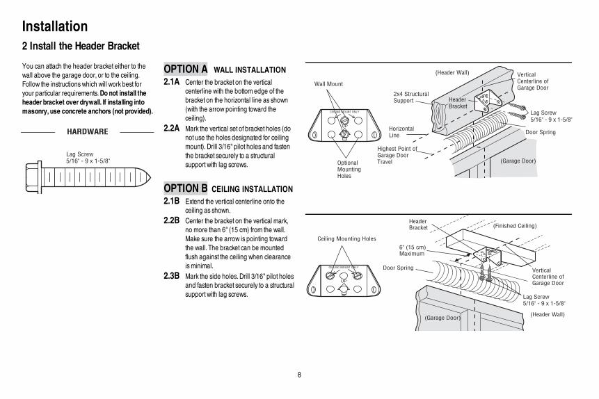
Your garage door opener is equipped with features to provide you with greater control over yourgarage door operation.Alert2CloseThe Alert2Close feature provides a visual and an audible alert that an unattended door is closing.Timer-to-Close (TTC)The TTC feature automatically closes the door after a specified time period that can be adjusted using aTTC enabled door control. Prior to and during the door closing the garage door opener lights will flashand the garage door opener will beep.MyQ®
MyQ® technology uses a 900MHz signal to provide two-way communication between the garage dooropener and MyQ® enabled accessories. Your garage door opener is compatible with up to 16 MyQ®
accessories.SECURITY+ 2.0™ REMOTE CONTROLS AND DOOR CONTROLSYour garage door opener has already been programmed at the factory to operate with your remotecontrol, which changeswith each use, randomly accessing over 100 billion new codes. Compatible withMyQ® and Security+ 2.0™ accessories, see page 35.NOTE: Older Raynor remote controls, door controls, and third party products are not compatible.
SECURITY+ 2.0TMAccessories MEMORY CAPACITY
Remote Controls Up to 12
DoorControls Up to 2 Smart Control Panels or 4 of any other Security+ 2.0™ door controls
Keyless Entries Up to 1
THE PROTECTOR SYSTEM® (SAFETY REVERSING SENSORS)When properly connected and aligned, the safety reversing sensors will detect an obstruction in thepath of the infrared beam. If an obstruction breaks the infrared beamwhile the door is closing, the doorwill stop and reverse to full open position, and the opener lights will flash 10 times. If the door is fullyopen, and the safety reversing sensors are not installed, or are misaligned, the door will not close froma remote control. However, you can close the door if you hold the button on the door control or keylessentry until the door is fully closed. The safety reversing sensors do not affect the opening cycle.
ENERGY CONSERVATIONFor energy efficiency the garage door opener will enter sleep mode when the door is fully closed. Thesleep mode shuts the garage door opener down until activated. The sleep mode is sequenced with thegarage door opener light bulb; as the light bulb turns off the sensor LEDswill turn off and whenever thegarage door opener lights turn on the sensor LEDswill light. The garage door opener will not go intothe sleep mode until the garage door opener has completed 5 cycles upon power up.LIGHTSThe garage door opener light bulbs will turn on when the opener is initially plugged in; power isrestored after interruption, or when the garage door opener is activated. The lights will turn offautomatically after 4-1/2 minutes. An incandescent A19 light bulb (100 watt maximum) or for maximumenergy efficiency a 26W (100W equivalent) compact fluorescent light (CFL) bulb may be used.Light FeatureThe garage door opener is equipped with an added feature; the lights will turn on when someoneenters through the open garage door and the safety reversing sensor infrared beam is broken. Foradded control over the light bulbs on your garage door opener, see page 29.USING YOUR GARAGE DOOR OPENERThe garage door opener can be activated through a wall-mounted door control, remote control,wireless keyless entry or MyQ® accessory.When the door is closed and the garage door opener isactivated the door will open. If the door senses an obstruction or is interrupted while opening the doorwill stop.When the door is in any position other than closed and the garage door opener is activatedthe door will close. If the garage door opener senses an obstruction while closing, the door will reverse.If the obstruction interrupts the sensor beam the garage door opener lights will blink 10 times. However,you can close the door if you hold the button on the door control or keyless entry until the door is fullyclosed. The safety reversing sensors do not affect the opening cycle. The safety reversing sensor mustbe connected and aligned correctly before the garage door opener will move in the down direction.
Features

28
USING THE DOOR CONTROLSYNCHRONIZE THE DOOR CONTROLTo synchronize the door control to the garage door opener, press the push bar until the garage dooropener activates (it may take up to 3 presses). Test the door control by pressing the push bar, eachpress of the push bar will activate the garage door opener.
Push Bar
LIGHT Button
SERVICE LED
LOCK Button
COMMAND LED
LEARN Button
PUSH BARPress the push bar to open or close the door.
LIGHT BUTTONPress the LIGHT button to turn the garage door opener lights on or off.When the lights are turned onthey will stay on until the LIGHT button is pressed again, or until the garage door opener is activated.Once the garage door opener is activated the lights will turn off after the specified period of time (thefactory setting is 4-1/2 minutes). The LIGHT button will not control the lights when the door is in motion.
The following features are accessible by lifting up the push bar:LEARN A DEVICEAny compatible remote controls, wireless keyless entry, or MyQ® accessories can be programmed tothe garage door opener by pressing the LEARN button the door control, see page 30.LOCKThe LOCK feature is designed to prevent activation of the garage door opener from remote controlswhile still allowing activation from the door control and keyless entry. This feature is useful for addedpeace ofmind when the home is empty (i.e. vacation).
AUTOMATIC LIGHTLight FeatureThe lights will turn on when someone enters through the open garage door and the safety reversingsensor infrared beam is broken.MAINTENANCE ALERT (MAS)This feature assists the homeowner in ensuring the garage door opener system stays in good workingcondition. When the garage door opener needs to be serviced (approximately 4500 garage dooropener cycles) the command (yellow) and service (red) LEDswill begin to alternately flash back andforth. The factory setting for the MAS feature is off and can be activated at time of installation. Contactyour installing dealer for service.
Door Control

29
Control Panel SetupLOCKNOTE: Your remote controls will NOT workwhen LOCK mode is active however yourkeyless entry will still allow access to yourgarage.
Activate: Press and hold the LOCK button for2 seconds. The command LEDwill flash as longas the lock feature is activated and yourhandheld remote control will not operate yourdoor at this time.Deactivate: Press and hold the LOCK buttonagain for 2 seconds. The command LEDwillstop flashing and normal operation will resume.
LOCK Button
Command LED
LIGHTTo change the amount of time the garage door opener lights will stay on:Press and hold the LOCK button until the garage door opener lights flash.* The time interval isindicated by the number of flashes.
Number of times garage door opener lights flash Time the garage door opener light stays on
1 1 1/2 Minutes
2 2 1/2 Minutes
3 3 1/2 Minutes
4 4 1/2 Minutes
To cycle through the time intervals repeat the step above.LIGHT FEATURE (Default is Active)Deactivate:Press and hold the LIGHT button until the garage door opener lights turn on, then off again.*Activate:Start with the garage door opener lights on. Press and hold the LIGHT button until the garage dooropener lights turn off, then on again.*NOTE: If the command LED is continuously blinking, the LOCK feature needs to be deactivated.
LOCK Button
LIGHT Button
Command LED
* Approximately 10 seconds
MAINTENANCE ALERT SYSTEM (MAS):Activate/DeactivatePress and hold the LEARN button. Then pressthe LIGHT button. The service LED will flashthe status; Active is 2 flashes and deactivatedis 3 flashes.
LEARN
Button
LIGHT
Button
Service
LED
Door Control
30
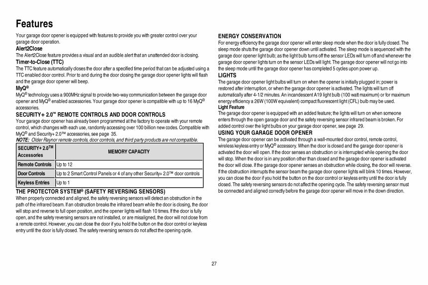
Your remote control has been programmed at the factory to operate with your garage door opener.Older Raynor remote controls are NOT compatible, see page 35 for compatible accessories. Programming can be done through the door control or the learn button the garage door opener. To programadditional accessories refer to the instructions provided with the accessory or visit www.raynor.com. If your vehicle is equipped with a Homelink®, you may require an external adapter depending on the make,model, and year of your vehicle. Visit www.homelink.com for additional information.
TO ADD,REPROGRAM,ORCHANGE AREMOTE CONTROL/KEYLESS ENTRY PINUSING THE DOORCONTROL
1 Press the LEARN button on the door controlto enter Programming Mode.
The command LED will flash once.
2 Press the LEARN button again, the LEDwillflash once.
The command LED will flash once again.
3 Remote Control:Press the button on the remote control that you wish to operateyour garage door.Keyless Entry:Enter a 4-digit personal identification number (PIN) of your choiceon the keyless entry keypad. Then press the ENTER button.
The garage door opener lights will flash (or two clicks will be heard)when the code has been programmed. Repeat the steps above forprogramming additional remote controls or keyless entry devices. Ifprogramming is unsuccessful, program the remote using the learnbutton.
OR
PIN
? ? ? ?
1 2ABC 3DEF
4GHI 5JKL 6MNO
7PRS 8TUV 9WXY
0 QZ* #
ENTER
0 QZ*
#
ENTER
PROGRAM USING THE GARAGE DOOR OPENER
1 Locate the Learn Button. 2 Press and immediately release the Learnbutton. The Learn LED will glow steady for30 seconds.Within 30 seconds...
3 Press and hold the button the remote control that you wish to use.Release the button when the garage door opener lights blink or two clicks are heard.If programming to other products, press the button a second time to activate products.
“click”
“click”
Remote Control

31
To Erase the Memory
ERASE ALL REMOTE CONTROLS AND KEYLESS ENTRIES1 Press and hold the learn button on garage door opener until the learn LED goes out
(approximately 6 seconds). All remote control and keyless entry codes are now erased.Reprogram any accessory you wish to use.ERASE ALL DEVICES (Including MyQ® enabled accessories)1 Press and hold the learn button on garage door opener until the learn LED goes out
(approximately 6 seconds).2 Immediately press and hold the learn button again until the learn LED goes out. All codes are
now erased.Reprogram any accessory you wish to use.
Remote Control

32
To prevent possible SERIOUS INJURY or DEATH from a falling garage door:• If possible, use emergency release handle to disengage trolleyONLY when garage door is
CLOSED.Weak or broken springs or unbalanced door could result in an open door falling rapidlyand/or unexpectedly.
• NEVER use emergency release handle unless garage doorway is clear of persons andobstructions.
• NEVER use handle to pull door open or closed. If rope knot becomes untied, you could fall.
DISCONNECTTHE TROLLEY1 The door should be fully closed if possible.2 Pull down on the emergency release handle.RECONNECTTHE TROLLEYThe lockout feature prevents the trolley from reconnecting automatically.1 Pull the emergency release handle down and back (toward the
opener). The door can then be raised and lowered manually as oftenas necessary.
2 To disengage the lockout feature, pull the handle straight down.The trolley will reconnect on the next UP or DOWNoperation, eithermanually or by using the door control or remote control.
NOTICE
NOTICE
MaintenanceEVERY MONTH• Manually operate door. If it is unbalanced or binding, call a trained door systems technician.• Check to be sure door opens and closes fully. Adjust if necessary, see page 24.• Test the safety reversal system. Adjust if necessary, see page 25.EVERY YEAR• Oil door rollers, bearings and hinges. The garage door opener does not require additional
lubrication. Do not grease the door tracks.EVERY TWO TO THREE YEARS• Use a rag to wipe away the existing grease from the garage door opener rail. Reapply a small layer
of white lithium grease to the top and underside of the rail surface where the trolley slides.NOTICE: To comply with FCC and/or Industry Canada (IC) rules, adjustment or modificationsof this transceiver are prohibited. THEREARE NO USERSERVICEABLE PARTS. Any changes or modifications not expresslyapproved by the party responsible for compliancecould void the user'sauthority to operate the equipment.Thisdevice complieswith Part 15 of the FCC rulesand ICRSS-210. Operation issubject to the following two conditions: (1) thisdevice maynot cause harmful interference, and (2) this device must accept any interference received, including interference that may causeundesired operation.ThisClassBdigitalapparatuscomplieswith Canadian ICES-003.
AVIS: Lesrèglesde la FCC et/ou d’Industrie Canada (IC) interdisent tout ajustement ou toute modification de ce récepteur. IL N’EXISTEAUCUNEPIÈCESUSCEPTIBLED’ÊTREENTRETENUEPAR L’UTILISATEUR. Tout changement ou toute modification nonexpressément approuvé par la partie responsablede la conformité peut avoirpour résultat d'annuler l'autorité de l'utilisateurde fairefonctionner l'équipement.Cet appareilest conforme auxdispositionsde la partie 15 du règlement de la FCC et de l'norme IC RSS-210. Son utilisation est assujettieauxdeuxconditoinssuivantes: (1)ce dispositif ne peut causerdesinterférencesnuisibles, et (2)ce dispositif doit accepter touteinterférence recue, ycomprisune interférence pouvant causerun fonctionnement non souhaité.Cet appareilnumerique de la classe Best conforme a la norme NMB-003 du Canada.
THE REMOTE CONTROL BATTERY
To prevent possible SERIOUS INJURY or DEATH:• NEVER allow small children near batteries.• If battery is swallowed, immediately notify doctor.To reduce risk of fire, explosion or chemical burn:• Replace ONLY with 3V2032 coin batteries.• DO NOT recharge, disassemble, heat above 212°F (100°C) or incinerate.
To replace the battery, pry open the case in the middle, then at eachside with the visor clip. Insert replacement battery positive side up (+).Replace the batteries with only 3V2032 coin cell batteries. Dispose ofold batteries properly.
To Open the Door Manually

33
Diagnostic ChartYour garage door opener is programmed with self-diagnostic capabilities. The UP and DOWNarrows on the garage door opener flash the diagnostic codes.
DIAGNOSTICCODE SYMPTOM SOLUTION
Up ArrowFlash(es)
Down ArrowFlash(es)
1 1 The garage door opener will not close and the lightbulbs flash.
Safety sensors are not installed, connected or wiresmay be cut. Inspect sensor wires for a disconnectedor cut wire.
1 2 The garage door opener will not close and the lightbulbs flash.
There is a short or reversed wire for the safety sensors. Inspect safety sensor wire at all staple pointsand connection points and replace wire or correct as needed.
1 3 The door control will not function. The wires for the door control are shorted or the door control is faulty. Inspect safety sensor wire at allstaple points and connection points and replace wire or correct as needed.
1 4 The garage door opener will not close and the lightbulbs flash.
Safety sensors are misaligned or were momentarily obstructed. Realign both sensors to ensure bothLEDs are steady and not flickering.Make sure nothing is hanging or mounted on the door that wouldinterrupt the sensors path while closing.
1 5 Door moves 6-8" stops or reverses. Manually open and close the door. Check for binding or obstructions, such as a broken spring or doorlock, correct as needed. Checkwiring connections at travel module and at the logic board. Replacetravel module if necessary.
No movement, only a single click. Manually open and close the door. Check for binding or obstructions, such as a broken spring or doorlock, correct as needed. Replace logic board if necessary.
Opener hums for 1-2 seconds no movement. Manually open and close the door. Check for binding or obstructions, such as a broken spring or doorlock, correct as needed. Replace motor if necessary.
1 6 Door coast after it has come to a complete stop. Program travel to coasting position or have door balanced by a trained technician.
2 1-5 No movement or sound. Replace logic board.
3 2 Unable to set the travel or retain position. Check travel module for proper assembly, replace if necessary.
Troubleshooting

34
DIAGNOSTICCODE SYMPTOM SOLUTION
Up ArrowFlash(es)
Down ArrowFlash(es)
4 1-4 Door ismoving stops and or reverses. Manually open and close the door. Check for binding or obstructions, such as a broken spring or door lock,correct as needed. If the door is binding or sticking contact a trained door systems technician. If door is notbinding or sticking attempt to reprogram travel (refer to page 24 ).
4 5 Opener runs approximately 6-8", stops and reverses. Communication error to travel module. Check travel module connections, replace module if necessary.
4 6 The garage door opener will not close and the lightbulbs flash.
Safety sensors are misaligned or were momentarily obstructed. Realign both sensors to ensure both LEDsare steady and not flickering.Make sure nothing is hanging or mounted on the door that would interruptthe sensor's path while closing.
The garage door opener can beep for several reasons:• Garage door opener has been activated through a device or feature such as Timer-to-
Close, garage door monitor or LiftMaster Internet Gateway, see page 27.My remote control will not activate the garage door:• Verify the lock feature is not activated on the door control.• Reprogram the remote control.• If the remote control will still not activate the door check the diagnostic codes to ensure
the garage door opener is working properly.My doorwill not close and the light bulbs blink onmy motor unit:The safety reversing sensor must be connected and aligned correctly before the garagedoor opener will move in the down direction.• Verify the safety sensors are properly installed, aligned and free of any obstructions.
My garage door opener light(s) will not turn off when the door is open:The garage door opener is equipped with a feature that turns the light on when the safety reversing sensorshave been obstructed or when the motion sensor on the door control detectsmovement in the garage. Thesefeatures can be disabled using the door control, see page 31 .My neighbor’s remote control opens my garage door:Erase the memory from your garage door opener and reprogram the remote control(s).The LEDs on the door control blink:If you have a Smart Control Panel installed and the TTC is set to a custom time, press the ON button on thePremiumMotion-Detecting Control Panel to set the time properly.My vehicle's Homelink® is not programming tomy garage door opener:Depending on the make,model, and year of your vehicle an external adapter may be required. Visitwww.homelink.com for additional information.
Troubleshooting

35
Accessories
895RGX 829LM
893RGX
41A7773-1
990LM
877MGX
MAX ACCESSORIESCompatible with Raynor® garage door openers manufactured since 1993.
MyQ® ACCESSORIES STANDARD ACCESSORIES
3-Button Remote Control:Includes visor clip.
Garage and Gate Monitor:Monitor open/closed status for up to 4 MyQ® compatible garage door openers or gate operators and close them from anywhere in the home.3-Button MAX Remote Control:
Includes visor clip.
Security✚ 2.0™ Wireless Door Control:Push bar, light feature and auxiliary button. Includes battery. SECURITY✚ 2.0™ compatible.
Surge Protector:The Garage Door Opener Surge Protector is designed to protect Raynor® garage door openers against damage from lightning and power surges. Easy to install.
MAX Wireless Keyless Entry:For use outside of the home to enable access to the garage using a 4-digit PIN.
828LG
823LM
825LMMyQ® Internet Gateway:Internet enabled accessory which connects to the computer and allows you to monitor and control garage door openers and lighting accessories enabled by MyQ® technology.
Remote Light Switch:Automatically control your lights using your garage door opener, a SECURITY✚ 2.0™ remote control or a MyQ® Internet Gateway. Simply replaces your current wired wall switch.
Remote Light Control:Automatically control your lights using your garage door opener, a SECURITY✚ 2.0™ remote control or a MyQ® Internet Gateway. Plugs into any interior outlet.
Extension Brackets:(Optional) For safety reversing sensor installation onto the wall or fl oor.
41A5281-1

WarrantyRAYNOR® ONE YEAR LIMITED WARRANTY
LIFETIME MOTOR AND BELT LIMITED WARRANTY
RAYNOR® (“Seller”) warrants to the fi rst retail purchaser of this product, for the residence in which this product is originally installed, that it is free from defects in materials and/or workmanship for a period of one year from the date of purchase, except that the motor and belt are warranted to be free from defects in materials and/or workmanship for the lifetime of the product while you own your residence. The proper operation of this product is dependent on your compliance with the instructions regarding installation, operation, and maintenance and testing. Failure to comply strictly with those instructions will void this limited warranty in its entirety.
If, during the limited warranty period, this product appears to contain a defect covered by this limited warranty, call 1-800-528-9131, toll free, before dismantling this product. You will be advised of disassembly and shipping instructions when you call. Then send the product or component, pre-paid and insured, as directed to our service center for warranty repair. Please include a brief description of the problem and a dated proof-of-purchase receipt with any product returned for warranty repair. Products returned to Seller for warranty repair, which upon receipt by Seller are confi rmed to be defective and covered by this limited warranty, will be repaired or replaced (at Seller’s sole option) at no cost to you and returned pre-paid. Defective parts will be repaired or replaced with new or factory-rebuilt parts at Seller’s sole option. [You are responsible for any costs incurred in removing and/or reinstalling the product or any component .]
ALL IMPLIED WARRANTIES FOR THE PRODUCT, INCLUDING BUT NOT LIMITED TO ANY IMPLIED WARRANTIES OF MERCHANTABILITY AND FITNESS FOR A PARTICULAR PURPOSE, ARE LIMITED IN DURATION TO THE APPLICABLE LIMITED WARRANTY PERIOD SET FORTH ABOVE FOR THE RELATED COMPONENT(S), AND NO IMPLIED WARRANTIES WILL EXIST OR APPLY AFTER SUCH PERIOD. Some States do not allow limitations on how long an implied warranty lasts, so the above limitation may not apply to you. THIS LIMITED WARRANTY DOES NOT COVER NON-DEFECT DAMAGE, DAMAGE CAUSED BY IMPROPER INSTALLATION, OPERATION OR CARE (INCLUDING, BUT NOT LIMITED TO ABUSE, MISUSE, FAILURE TO PROVIDE REASONABLE AND NECESSARY MAINTENANCE, UNAUTHORIZED REPAIRS OR ANY ALTERATIONS TO THIS PRODUCT), LABOR CHARGES FOR REINSTALLING A REPAIRED OR REPLACED UNIT, REPLACEMENT OF CONSUMABLE ITEMS (E.G., BATTERIES IN REMOTE CONTROL TRANSMITTERS AND LIGHT BULBS), OR UNITS INSTALLED FOR NON-RESIDENTIAL USE. THIS LIMITED WARRANTY DOES NOT COVER ANY PROBLEMS WITH, OR RELATING TO, THE GARAGE DOOR OR GARAGE DOOR HARDWARE, INCLUDING BUT NOT LIMITED TO THE DOOR SPRINGS, DOOR ROLLERS, DOOR ALIGNMENT OR HINGES. THIS LIMITED WARRANTY ALSO DOES NOT COVER ANY PROBLEMS CAUSED BY INTERFERENCE. UNDER NO CIRCUMSTANCES SHALL SELLER BE LIABLE FOR CONSEQUENTIAL, INCIDENTAL OR SPECIAL DAMAGES ARISING IN CONNECTION WITH USE, OR INABILITY TO USE, THIS PRODUCT. IN NO EVENT SHALL SELLER’S LIABILITY FOR BREACH OF WARRANTY, BREACH OF CONTRACT, NEGLIGENCE OR STRICT LIABILITY EXCEED THE COST OF THE PRODUCT COVERED HEREBY. NO PERSON IS AUTHORIZED TO ASSUME FOR US ANY OTHER LIABILITY IN CONNECTION WITH THE SALE OF THIS PRODUCT.
Some states do not allow the exclusion or limitation of consequential, incidental or special damages, so the above limitation or exclusion may not apply to you. This limited warranty gives
you specifi c legal rights, and you may also have other rights, which vary from state to state.
36

37
Repair PartsRail Assembly Parts Installation Parts
1
3
4
5
7
6
2
1
2
3
4
5
6
7
8
9
1012
11
Description Part Number
1 Belt - for 7 foot door 41A5434-11
Belt - for 8 foot door 41A5434-13
Belt - for 10 foot door 41A5434-14
2 Belt Pulley Bracket 41B5424
3 Master Link 4A1008
4 One-Piece Rail 7 feet (2.1 m)
2777BD
One-Piece Rail 8 feet (2.4 m)
2778BD
One-Piece Rail 10 feet (3 m)
2770BD
5 Trolley Assembly 41B3869-3A
6 Tensioner Assembly 41B4103
7 Trolley Threaded Shaft 109B48
Not Shown
Owner’s Manual 114A4620
Description Part Number
1 Curved Door Arm 178B35
2 Door Bracket with Clevis Pin and Fastener
41A5047-1
3 Emergency Release Rope and Handle
41A2828
4 Header Bracket with Clevis Pin and Fastener
41A4353-1
5 Remote Control Visor Clip 29B137
6 Safety Sensor Bracket 41A5266-1
7 Safety Sensor KitReceiving and sending sensors with 2-conductor wire
41A5034
8 Straight Door Arm 178B34
9 White and Red/White Wire 41B4494-1
10 3V2032 Lithium Battery 10A20
11 Remote Control 893RGX
12 Multi-function Door Control 041A7185-2

38
4
126
14
10
1
15 11
7
13
5
2
9
8
6 7
3
Repair PartsGarage Door Opener Parts - MODEL 8355RGD
Description Part Number
1 Cover with Screws 41A4371
2 Gear and Sprocket 41A4885-5
3 Drive and Worm Gear 41A2817
4 Line Cord 41B4245
5 Front End Panel 41A7756
6 Light Socket 41C279
7 Light Lens 041A7562-1
8 Capacitor 30B532
9 Capacitor Bracket 12A373
10 Terminal Block 41A3150
11 Motor 41A7442
12 Travel Module 41D7742-7
13 Cover 041A7619-6
14 Logic Board 45ACT
15 Logic Board End Panel 41D216
Not Shown
Dual Wire Harness Kit 41A7790
Contact Information
Before calling, please have the model number of the garage door opener. If you are calling about a Troubleshooting issue, it is recommended that you have access to your garage door opener while calling. If you are ordering a repair part please have the
following information: part number, part name, and model number.
Address repair parts order to:RAYNOR® GARAGE DOORS6050 S. Country Club Rd.Tucson, AZ 85706
For installation and service information call:1-800-472-9667
Or visit us online at:www.raynor.com

39
Notes

© 2013, The Chamberlain Group, Inc.114A4620 All Rights Reserved