
PRELIMINARY EVALUATION OF SMALL HYDROELECTRIC …akenergyinventory.org/hyd/SSH-1980-0421.pdf ·...
33
PRELIMINARY EVALUATION OF SMALL HYDROELECTRIC POWER DEVELOPMENT AT SCAMMON BAY, ALASKA ALASKA DISTRICT CORPS OF ENGINEERS DECEMBER 1980
Transcript of PRELIMINARY EVALUATION OF SMALL HYDROELECTRIC …akenergyinventory.org/hyd/SSH-1980-0421.pdf ·...

PRELIMINARY EVALUATION OF SMALL HYDROELECTRIC POWER
DEVELOPMENT AT SCAMMON BAY ALASKA
ALASKA DISTRICT CORPS OF ENGINEERS
DECEMBER 1980
SUMMARY
Scammon Bay is a village of approximately 200 people located on the Kun River near the Bering Sea The village currently derives all of its electrical energy from diesel fired generation
The Corps of Engineers was authorized by Congress to conduct feasibility studies for the development of small hydroelectric power facilities at isolated villages throughout Alaska During the preparation of the feasibility studies the Alaska Power Authority requested an evaluation of hydroelectric power at the community of Scammon Bay This preliminary analysis is in response to tnat request
This report includes a preliminary engineering economic and financial evaluation of possible development of hydroelectric power on a small stream near Scammon Bay The estimated cost is $1010000 and the project WOUld have a peak capacity of 150 killowatts Based on financial criteria estaolished by the Alaska Power Authority (30 year pay-back 10 percent financing) the project would produce energy for approximately 31centkWh during the first year with very little increase in future years This figure includes interest amortization operation and maintenance The current figure for diesel fired generation is approximately 30centKWh which is expected to double in 10 years Neither of these figures includes administrative overhead taxes or insurance
Although hydroelectric generation is initially more expensive by the second year of operation it should prove to be less expensive than diesel and by year 2000 hydroelectric power would be less than one fourth as expensive as diesel This is based on an assumed inflation rate of 7 percent and diesel fuel escalating at 35 percent above inflation
---
TABLE OF CONTENTS
Page Number
INTRODUCTION
COMMUNITY PROFILE 2
GENERATION FACILITIES 5
ENERGY DEMAND 6
HYDROLOGY 9
DESIGN FEATURES 14
ENVIRONMENTAL IMPACTS 18
COST ESTIMATE 19
ECONOMIC ANALYSIS 21
FINANCIAL ANALYSIS 24
INTRODUCTION AUTHOR IZATION
The Corps of Engineers small hydropower study was authorized by Congress in 1976 The small hydropower study was undertaken to determine the feasibility of installing small hydroelectric systems in isolated villages throughout Alaska This feasibility study is being conducted as part of that larger study
SCOPE OF WORK
This report is limited in scope to the analysis of hydropower at Scammon Bay Other alternatives are currently being studied by the AlasKa Power Authority The information proviaed in this report is preliminary accurate measurements of the instream flow have only been made since late July 1980 The proposed plan presented herein is based on the best information available however due to the limited data the conceptual design and resulting cost estimate are sUbject to change as additional information becomes available during 1981 Project size may be reduced if stream-flow is less than predicted
BACKGROUND TO CURRENT STUDIES
In August 1979 the Alaska Power Administration in conjunction with the Alaska Village Electrical Cooperative (AVEC) visited 15 potential hydropower sites located near villages served by AVEC Of those sites visited Scammon Bay appeared to be the most feasible hydropower project As a result the Alaska Power Administration recommended that the Corps of Engineers pursue the feasibility evaluation under its small hydropower authorization
THE STUDY
The primary Objective of this stUdy is to determine the feasibility of hydropower development at Scammon Bay and if feasible assist in implementing the project at the earliest possible date The need to reduce the bush communities dependence on diesel fuel is imperative to their future well being
Federal funds to construct this project would require Congressional authorization under existing regulations however Congress may change this procedure and provide the Corps of Engineers a continuing authority to build small hydropower projects Pending legislation includes authorshyity which would allow projects up to 25000 kW capacity to be constructed by the Corps of Engineers If this legislation passes action could be taken to construct economically feasible and environmentally acceptable small hydropower projects in a timely manner
COMMUNITY PROFILE
HISTORY
Scammon Bay is located to the north of the Askinuk Mountains in the Yukon-Kuskokwim Delta on the south bank of the Kun River one mile from the Bering Sea (Plate 1) In earlier times the village located at Sc ammon Bay was known in Esk imo as Mar i ak n The v ill age was 1 ater named after the nearby bay which honors Captain Charles M Scammon who served with the Western Telegraph Expedition from 1856-1867 The name Scammon Bay became commonly applied to tne village in 1951 when a post office of that name was established
SOC IO-ECONOMI CS
Transportation
Scammon Bay is accessible by air water and winter trail Transport fuel and bulk supplies are barged to the community from June to Septemoer The Kun River serves approximately 60 privately owned boats providing transportation to fish and berry camps
A 2BOO-foot gravel airstrip north of the city enables daily scheduled commercial air service PrinCipal air carriers include Sea Airmotive and Wien Scammon Bay has approximately one mile of gravel road for use by the few vehicles in town Snowmachines owned by nearly every househo1a in the community are the major form of transportation in winter
Fishing
The primary economic act ivity of Scammon Bay occurs during the summer when most residents are involved in commercial fishing As of 1978 the Yukon District had issued 40 gill net permits to Scammon Bay residents Commercial species include salmon and to a lesser extent herring Herring are anticipated to become a larger portion of the cash economy with the investment by the Alaska Renewable Resource Corporation in the construction of approximately 10 herring fishing boats at Scammon Bay In addition to these commercial catches non-cash landings include whitefish blackfish needlefish smelt and tomcod
Trade and Services
Year-round employment in the city is available through local government and trade In the trade sector employers include the airport four minor stores and the general store Some residents also sell handmade grass baskets or ivory-carved jewelry and other handicrafts
Government
Scammon Bay was incorporatea as a second class city in 1967 The seven member city council selects the town mayor and administrator In aoaition the city employs a clerk secretarytreasurer police and
2
maintenence personnel These positions are funded through the Comprehenshysive Employment Training Act (CETA) program Other government supported employment sources include the Bureau of Indian Affairs school the Rural Parent-Child program and seasonal firefighting for the Bureau of Land Management
Subsistence Activities
Income from the aforementioned activities is supplemented by sUbsistence hunting and gathering and to some extent assistance payments In addition to fish residents of the area hunt walrus seal geese swans cranes ducks loons and ptarmigan In the fall various types of berries such as blueberries cranberries and salmon berries are harvested bull
Population
In 1979 the population of Scammon Bay was 191 Census figures for 1970 show that the population is 100 percent native with median ages of 175 and 160 for males and females respectively Table 1 shows population figures for Scammon Bay The reported figures indicate an annual growth rate of approximately 2 percent
Year
1939 1950 1960 1970 1979
Employment Overview
TABLE 1
HISTORIC POPULATION OF SCAMMON BAY
ulation
88 103 115 166 191
Table 2 shows employment in Scammon Bay for the year 1979
3
TABLE 2
SCAMMON BAY 1979 EMPLOYMENT BY INDUSTRY
Part Time
Gill net t i ng 40Y BLM CETA Airport BIA School Retai 1 Parent-Child Program Handicrafts
TOTAL 40
Source
Alaska Department of Community and Regional 1 Based on number of gillnet permits only_ greater Number Unknown
4
Year Round
11 1 9 8 2
31
Affairs Actual participation is
GENERATION FACILITIES
Prior to 1974 Scammon Bay was not associated with any formal electric utility system During this period most households either utilized private generators or were not electrified Like most bush communities the local Bureau of Indian Affairs (BIA) elementary school had its own generating capacity As a result of the informal system electric consumption records from this era are unavailable
In 1974 Scammon Bay joined the Alaska Village Electric Cooperative Inc (AVEC) a nonprofit electric cooperative membership corporation AVEC is the States largest single supplier of electricity to rural areas and provides power to 48 communities throughout western Alaska The average population of AVEC supplied communities is approximately 300 All AVEC power is diesel generated The uti1itys diesel units at Scammon Bay are summarized below
1 - 50 kW 1200 rpm KATO (1971) 1 - 75 kW 1200 rpm KATO (1971)
50 kW 75 kW
125 kW
AVEC is currently in the process of modifying this capacity by boosting each unit from 1200 rpm to 1800 rpm The total capacity of the system will thus be increased to about 175 kW (105 kW and 70 kW) In addition to AVEC generation the local BIA elementary school and high school maintain standby generators The specifications of these units are summarized here
High School BIA School
1-100 kW 1-35 kW 1-25 kW
Newage Stawford Kohler Kohler
100 35 25
160 kW
The recently acquired high school generator presently has very few hours of operating time The BIA units vary from 10 to 15 years in age Presently both schools are customers of AVEC but the school generating capacity is often needed for standby purposes
5
ENERGY DEMAND HISTORIC
Since JOlnlng AVEC Scammon Bay has participated in the cooperatives record keeping system Unfortunately records were not kept di11igent1y in the early years resulting in incomplete and missing forms In 1979 AVEC generation for Scammon Bay totaled 269310 kWh with a peak load of 78 kW
The total energy generation at Scammon Bay is unknown The BIAs generators are known to operate a significant proportion of the time but no records of output have ever been kept For the purpose of this report it has been estimated that the BIA generator produces an additional 15 above AVEC generation This would increase the combined 1979 AVEC and BIA energy generation to 309700 kWh
In addition to the BIA school (three classrooms) and new high school (6500 sq ft) the community has a variety of public and residential structures which comprise the electricity demand of Scammon Bay AVEC estimates that the recently constructed high school will add approxishymately 35 kW to the systems peak demand Public buildings include the community center the traditional council building armory clinic post office Luther Aguchak Memorial Building and two churches Four stores several warehouses a movie theater and the AVEC building are also located in the city There are approximately 45 single family dwellings in Scammon Bay most are of wood-frame construction Of these 15 were built in 1970 by the Alaska State Housing Authority In all about 60 structures are served by AVEC
AVECs total dependence upon diesel generation has resulted in ever spiraling costs in recent years The cooperatives base rate currently stands at 408cent per kWh The extremely complicated accounting and financing practices of this utility make the derivation of Scammon Bays generating costs difficult The rate quoted above for instance applies to the first 75 kWh of residential use a category many households fall into Consumption above this level is charged at about 75 percent of this rate Commercial rates on the other hand are 378cent per kWh All rates include a 36cent per kWh fuel surcharge The fuel surcharge does not fully reflect the fuel cost component of AVECs rates It is intended strict1y to anticipate rising fuel costs thus protecting consumers against abrupt rate increases
The overall utility rates corresponding to these years are given in Table 5 Rates for consumption above 75 kWh and commercial use have remained roughly proportional to the present schedule
6
TABLE 5
AVEC RESIDENTIAL RATE 1975-1980 (75 kWh)
Year Rate (cent per kWh)
1975 219 1976 228 1977 290 1978 342 1979 367 1980 408
For electrical generation fuel prices have been the principal source of rising costs The average cost of diesel fuel delivered to AVEC villages since 1973 is shown in Table 6
Table 6 AVERAGE COST OF DELIVERED FUEL TO ALL AVEC VILLAGES 1973-80
Year Cost ($ga1)
1973 1974 1975 1976 1977 1978 1979 1980
035 052 058 065 072 078 097 133
Scammon Bay which takes a small annual shipment relative to other AVEC villages (20000 gal) experiences higher than average costs The price of diesel for Scammon Bay currently stands at $135 per gallon as compared to $133 on a system wide basis Regardless of this differenshytial Scammon Bay pays the same electrical rates as do other AVEC villages
FUTURE DEMAND
For this analsis a 1981 energy demand of 416000 kWh is used This was derived by assurnming a 5 percent per year energy increase above AVECs 1979 generation plus an additional 15 percent generated by the BIA generators Additional generation to serve the high school is estimated at 5 kW base load with an average demand of 25 kW during school hours This generated output s summerized in Table 7 bull
7
Table 7
SUMMARY OF ESTIMATED 1981 GENERATION (kWh)
AVEC BIA HIGH SCHOOL
TOTAL
Estimated Community Need Estimated proportion generated by BIA
296900 44500 75000
416400
Estimated yearly High School load (served by AVEC or Standby)
No attempt has been made to project electrical energy needs beyond 1981 The on-going study being conducted by NORTEC for the Alaska Power Authority should address these needs Assumming future energy needs are at least equivalent to the projected 1981 estimates the proposed hydropower projects feasibility should not be dependent on high future energy forcasts
8
HYDROLOGY
Only one hydropower site is located close enough to Scammon Bay to be potentially feasible for development at this time This stream flows through town and serves as the community water supply
BASIN DESCRIPTION
The basin is within an area of maritime influence which is prevalent over the Yukon-Kuskokwim Delta Although the Askinuk Mountains are adjacent to Scarrlmon Bay they are relatively small in height (1OOO-2000 foot) and create minor orographic changes in the climate In general the area surrounding Scammon Bay is tundra covered flat ana marshy land with oxbow lakes similar to other areas in the Yukon-Kuskokwim Delta
STREAMFLOWS
The village has historically acquired its water supply from the creek which flows from the Askinuk Mountains In 1976 the Public Health Service (PHS) built a community water system that treated the water with chlorine and fluoride and installed a piping network Although the village utilizes a portion of the creek for water supply there are no records of the amount of streamflow which has actually occurred During July 1980 a water measurement structure (Parshall Flume) was installed to collect data during the upcoming year and to verify the assumed streamflow values As this data becomes available it will be possible to make final design adjustments that may be warranted
Based upon measured flows taken near the village and correlated to the damsite the discharge and energy estimates shown in Table 8 have been made The months of July August September and October are actual measured monthly average flows The other monthly flows are based on the current best estimates considering climatic conditions known basin characteristics and conversations with the local villagers Measurements taken at the damsite and in town indicate that adequate residual flow will be left for water supply purposes
9
TABLE 8 ESTIMATED MONTHLY ENERGY PRODUCTION
TIME DISCHARGE POWER ENERGY (Months) (cfs) (kw) (kwh)
Oct 1 50 46 34000 Nov 125 38 27000 Dec 100 30 22000 Jan 100 30 22000 Feb 080 24 16000 Mar 100 30 22000 Apr 200 61 44000 May 1000 150 111000 Jun 600 150 108000 Jul 200 61 45000 Aug 200 61 45000 Sep 150 46 33000
TOTAL 529000
Maximum capacity has been tentatively set at 150 kW
The project has been initially sized at 150 kW With a single unit of the type proposed efficient operation will be possible over the range of 08 to 46 cfs This should cover the majority of the flows avai1aD1e The turbine would only develop the installed capacity in May and June when demand is relatively low Dut any necessary size reduction during final design should have little effect on the total usable energy output of the project
CLIMATE
The area has a maritime influence as indicated by its relatively moderate temperatures and precipitation The Askinuk Mountains have a minor orographic -influence on the cl imate at Scammon Bay such that the various pressure systems approaching from the ocean or the Yukon-Kuskokwim Delta would have a direct effect on the village There are no glaciers at the head of the stream which could effect the climate or the streamflow
The nearest climatological station is located at Cape Romanzof Air Force Station approximately 15 air miles away Although Cape Romanzof is at approximately the 435-foot elevation and has a Soutnwest exposure it represents the best approximation of weather at Scammon Bay
Temperature
Temperature data was collected from the Climatological Data National Oceanic and Atmospheric Administration (NOAA) for the period of 1953-1978 Tne monthly maximums minimums and averages are illustrated in Table A The average temperature range during the summer and winter respectively are 34deg F to 49deg F and between 9deg to 31deg F Recorded extremes are _26deg F and 79deg F
10
Precipitation
Precipitation data was also collected from NOAA records for the period of 1953-1978 The monthly average maximum and maximum 24-hour preciptiation are shown in Table A The average monthly precipitation ranges between 098 and 500 inches with an annual average of 2545 inches The maximum monthly precipitation for the period of record is 1050 inches with the maximum 24-hour precipitation being 277 inches
Snow
Snow pack data was collected from NOAA records for the same period as temperature and precipitation The average snowpack on the first of each montn with the standara deviation is illustrated in Table 9 Tne standard deviation of the snowpack indicates that over the period of record the snowpack nas varied considerablYA
Wind
Wind data was obtained from the Arctic Environmental Information Data Center through Mr James Wise It was also taken at Cape Romanzof AFS and is illustrated in Table 10 The data indicates the prevailing wind is from the northeast for all months of the year with the exception of July and August when it is from the south-southwest The mean annual velocity is 156 mph while the maximum mean velocity for the year is 162 mph
11
TABLE 9 CAPE ROMANZOF
CLIMATOLOGICAL DATA II
PRECIPITATION~I JAN FEB MAR APR MAY JUN JUL AUG SEP OCT NOV DEC ANNUAL
AVERAGE 111 098 125 97 128 213 295 500 462 239 156 121 2545 MAX MONTH 4 17 425 683 344 372 431 645 878 1050 609 546 414 1050
MAX 24 HOUR 099 1 15 120 090 074 188 195 277 209 134 197 130 277
TEMPERATURE
AVERAGE 129 97 135 207 344 433 492 492 437 311 226 128 286 MAXIMUM 49 48 46 60 63 72 79 73 63 60 43 48 79 MINIMUM -23 -26 -26 -12 3 25 31 33 23 4 -7 -23 -26
SNOW PACK ~
AVERAGE 78 11 8 153 186 129 14 00 00 00 O 1 29 59 N
STANDARD DEVIATION 68 97 14 1 206 83 33 00 00 00 064 32 57
STATION INFORMATION LATITUDE - 61 0 46 LONGITUDE - 166 0 03 I ELEVATION - 434 I
Y From Climatological Data 1953 through 1978
21 Rainfall in inches
11 Snow pack (including snow and sleet) on the ground~ in inches on the first of each month
TABLE 10 CAPE ROMANZOF WIND DATA
(MPH)
SUBJECT JAN FEB MAR APR MAY JUN JUL AUG SEP OCT NOV DEC ANNUAL
Prevailing Wind Mean Velocity 192 202 170 169 138 118 96 118 118 143 168 178 156
Direction NE NE NE NE NE NE SSW SSW NE NE NE NE NE
Time 169 214 17 1 152 180 126 147 130 166 197 186 213 162
Maximum Mean
I- Velocity 210 202 179 180 145 129 114 118 14 1 157 174 187 162
w Direction NNE NE NNE NNE NNE NNE NNE SSW NNE NNE NNE ENE NNE
Time 142 214 145 140 99 11 7 78 130 165 153 11 3 86 126
DESIGN FEATURES
Hydroelectric power would be developed from the spring fed stream which originates south of Scammon Bay and flows through the village (See Plate 2) The stream flows from approximately elevation 800 to elevation 50 where it merges with the main channel of the Kun River A small reservoir would be excavated upstream of a rock-filled gabion dam which would be constructed at elevation 596 about 3500 feet from the town proper A penstock would run from the intake structure of the dam to an aboveground powerhouse located near the villages school An open channel tailrace approximately 50 feet in length would be excavated from the powerhouse to the main stream channel Several viable alternatives for the installation of the penstock and for the type of pipe to be used are presented here Further study of these alternatives will be completed prior to final design of the Scammon Bay Hydropower Project
WATERWAYS
An 8-foot high dam would be constructed from standard manufactured galvanized steel gabions filled with rocks taken from the reservoir excavation and from the stream itself (Plate 3) A cut-off wall would be constructed of sack crete at the center of the dam This cut-off would extend approximately 9 feet below the existing ground surface and its top would be flush with the top of the dam at elevation 600 The dam would extend about 50 feet across the stream gully and would include a spillway with a 10-foot long weir which is 3 feet lower than the top of the dam
A drop box type intake structure with a top elevation 596 would be prefabricated of corrosion resistant steel with a trash rack located either on top or at the upper siaes of the box The trashrack would be made from a standard heavy duty steel grating The bottom of the reservoir would be sloped toward the stream to prevent rocks and other debris from accumulating around the intake box Reservoir excavation woula be limited to elevations below 598 with a minimum of 1 on 3 slopes for all embankments
PENSTOCK
Two alternatives were studied for the installation of tne l2-inch diameter penstock and three types of pipe were considered for conveying water from the reservoir to the powerhouse For both alternatives the invert of the penstock at the intake structure is at elevation 593 4 lt
feet below the minimum pool elevation 597 and 1 foot above the finished bottom grade of the reservoir at elevation 592 A sluice gate would be installed to regulate the flow through the penstock and for emergency operation The penstock would be placed on an average 135 percent slope whether above or below ground construction is used Under Alternative No1 the penstock would be buried about 2 feet below existing grade A trench would be excavated and backfilled as required The penstock would be anchored and supported as required Penstock Alternative No2 would consist of a partly buried pipe about 100 feet in length near the dam
14
and the rest would run aboveground supported on piers and anchored as required The exposed portion of the penstock would be insulated for thermal protection A steel penstock is found more suitable for aboveground installation because it would be more durable against natural disaster or vandalism
For both alternatives the penstock would cross the stream at approximately 550 feet downstream of the dam The minimum working pressure for the penstock would be at least 250 psi and the thickness of the shell would be 10 gao minimum for steel and 01875 inch for reinforced plastic pipes Three viable options for the types of penstock pipe were considered a standard welded steel pipe a spiral weld lockshyseam pipe and a reinforced plastic mortar (RPM) pipe Initial economic evaluation indicated that the RPM pipe was the most inexpensive in material and handling costs This particular pipe is also lightweight and highly corrosion resistant however it is susceptible to vandalism when installed aooveground The final selection of the type of pipe would be made at a later design stage Therefore in this analysis all three alternatives are being addressed for general feasibility They will be evaluated further with more serious consideration and emphasis on performance applications in Alaska For cost estimating purposes buried spiral welded pipe was used
POWER PLANT
The penstock would connect to a valve upstream of the turbine in the valve room located within the powerhouse The powerhouse would be located at elevation 100 and would be built on concrete slab The finished floor elevation of the slab would be about 4 feet above the main stream water level Three sites for the powerhouse were con-sidered but geological findings proved that two of the sites are not suitable due to potential flooding andor soil creep
An open channel tailrace would be excavated below the powerhouse A small energy dissipator structure would be located at the end as near as possible to the mainstream channel to prevent erosion of the embankments
Powerhouse Oeseri ion
The equipment would be housed in a small 10xll structure consisting of a concrete draft tube and equipment floor slab The structure will be prefabricated steel rather than the concrete block and wood as shown in Plate 4 Ventilation would be provided by a wall mounted fan Double doors for ease of equipment removal are proposed The generator is not intended to be fire protected Plate 1 shows the transverse section and plan of the powerhouse
15
Turbine
The turbine would be a standardized horizontal axis impulse or Turgo impulse turbine with one or two nozzles one of which would be adjustable The turbine would operate at 1800 rpm and would be directly coupled to the generator shaft A jet deflector would be provided for rapid divershysion of the water from the wheel at load rejection A valve would automatically close slowly to prevent overpressure in the penstock The turbine would be specified to discharge from 08 to 46 cfs while operating at 460 feet net head
Arrangements utilizing Francis Turbines and pumps operating as turbines were also investigated however because of the wide flow variation multiple units would be required thereby increasing the cost of the mechanical and electrical equipment Also the use of pumps as turbines would result in lower average operating efficiencies Prior to the final selection of the turbine type a review of applicable types will be made Shown on the drawings is a single jet Turgo Impulse Turbine
Generator
The generator would be a synchronous type rated 150 kW (188 kVA at 08 pf) l-Phase 60 Hz 120240 Volt 1800 rpm provided with a drip proof guarded enclosure and have a 80deg C temperature rise (over 40deg C ambient) capable of 10 percent overload
Excitation System
The excitation system would consist of a brushless (rotating rectifier) exciter with a saturable transformer automatic voltage regulator This system would be provided as part of the generator
Generator Circuit Breaker
The generator circuit breaker would be furnished as part of the generator package
Unit Control and Protective Equipment
The control and protective equipment would be furnished as part of the generator package
Station Service Equipment
The station service equipment would consist of a 120240 volt distribution panel to supply lighting outlets and other miscellaneous loads
Low Level Alarm
A low level alarm system at the intake structure would be utilized to shut thesystem down should water levels drop to a point where air may enter the penstock
16
Transmission tern
The project power would be transmitted through a local distribution system The connection to the existing distribution system would be by overhead line through a wall mounted weatherhead fitting
17
ENVIRONMENTAL IMPACTS
Fish and wildlife resources would not be significantly affected by small hydropower development on the stream running through Scammon Bay The small spring fed stream does not support resident or anadromous fish and there are no wildlife species dependent on the project area Although waterfowl and shorebirds are abundant in the immediate area there are no known resting nesting or feeding occurring in the area of the proposed projects influence The US Fish and Wildlife Service stated the greatest impact of the project could be erosion caused by mechanized equipment moving on the steep slopes underlain by permafrost Removal of the thin protective vegetative layer could allow permafrost to thaw resulting in ground subsidence and subsequent creation of deep gullies from erosion With construction occurring within the stream gully where permafrost is not present erosion would be minimal
18 bull
COST ESTIMATE
Two different schemes including above ground and buried penstocks were considered for Scammon Bay In all three penstock materials were considered for use steel welded spiral welded and rmp (plastic) pipe The costs for the various schemes and alternatives ranged from a low of $990000 to a high of $1250000 Additional data and design is required to determine the best alternative for the site before a final decision is made The cost estimate was based on a buried spiral welded penstock The following cost estimate does not include land acquisition which is assumed to be local responsibility
ITEM DESCRIPTION
MOB amp PREP WORK
INTAKE WORKS
Reservoir Excavation (common)
Intake Structure stainless steel drop box (3 wide x 6 long x 6 deep)
Trashrack Std Steel Grating 18 SF
DAM AND SILL (50 FT)
Excavation (common)
Concrete
Reinforcement
Gabion (rock) (Std Manufacture) 6 long x 3 wide x l deep
Backfi 11 (gravel)
Steel Gate (std sluice gate) 12 dia (low head type)
PRELIMINARY COST ESTIMATE
QUANTITY
1
70
400
41-5
55
50
2500
200
15
1
19
UNIT
LS
CY
LB
LB
CY
Cy
LB
EA
CY
LS
UNIT PRICE
$
2000
800
200
2000
60000
130
20000
2000
TOTAL
$300000
1400
3200
830
1100
30000
3250
40000
300
3000
ITEM DESCR I PTI ON QUANTITY UNIT UNIT PRICE TOTAL
Riprap 15 CY 11000 1650
WATERWAYS
Penstock 12dia 3500 LF Spiral weld 61250 LB 1 60 98000
Ring stiffeners exp anc hors anchor supports 4288 LB 200 8576
ANCHOR amp THRUST BLOCKS
Concrete 12 CY 60000 7200
Excavation (common) 3500 CY 500 17500
Backfill (common) 3400 CY 300 10200
POWER PLANT
Powerhouse LS 163000
TAILRACE CHANNEL
Excavation (common) 45 CY 1000 450
Riprap 15 CY 110 00 1650
TRANSMISSION LINE
(hook-up to exist city line)
wood poles cables transformer etc 1 LS 30000
SUB TOTAL COST = $721306 20 Contigencies 144694 CONTRACT COST = $866000 Engineering amp Design = 70000 Supervision amp Adminis-tration = 74000
TOTAL PROJECT COST $1010000
20
ECONOMIC ANALYSIS
This evaluation is based exclusively on economic benefits that can be derived from hydropower development Evaluation of the Scammon Bay proshyposal was accomplished by comparing the benefits to accompanying costs The benefit value of hydroelectric power is measurea by the cost of providing the equivalent power from the most likely alternative source (diesel) The evaluation has been conductea in accordance with methods requested by the Alaska Power Authority
PROJECT COSTS
Interest During Construction
As the proposed development would be constructed in one season interest during construction would not enter into project costs
Annual Costs
The Alaska Power Authority has specified that under an inflation free economic analysis a discount rate of 3 percent is appropriate By applying the capital recovery factor associated with a 3 percent interest rate and a 50-year economic life the investment cost can be transformed into an average annual fixed cost Adding operations maintenance and replacement costs a total annual cost is established for the purpose of determining comparability and feasibility
Operation Maintenance and Replacement Costs (OMampR)
An OMampR cost of $8000 annually has been est imated for the Scammon Bay hydropower project This figure does not include AVECs existing charges
Tota 1 Average Annumiddota 1 System Costs
The average annual costs for the various plans of development are based on a 3 percent annual interest rate and a 50 year economic life These costs also reflect transmission tie in facilities access (but not land aquisition) replacement costs annual operation and maintenance ana other associated project costs
PROJECT BENEFITS
The benefit value of hydroelectric power is measured by the cost of providing the equivalent power from the most likely alternative source Diesel generation is currently the most likely alternative for Scammon Bay
21
Power Values
The project under examination would displace diesel currently utilized for power generation Thus Scammon Bays current power costs (as can be best approximated) will be employed to access the costs of continued diesel generation As of 1980 AVECs per kWh costs divided as follows
Fuel O~ Depreciation Taxes Insurance Interest
AVEC Generation cost per kWh excluding administration and
transmission costs
1693 1266
25
04
03
06 2997cent
As measured by the base rate administrative and transmission costs total 73cent per kWh Adding a fuel surcharge of 36cent per kWh yields the original rate of 408cent per kWh As mentioned this rate applies only to the first 75 kWh of residential use Although industrial and larger residential users enjoy lower rates the base rate will be considered representative of Scammon Bays power costs
Credit for Energy and Capacity
Opportunities exist for displacing energy which could alternatively be produced by existing thermal plants The value of thermal energy that would be displaced is dependent on fuel costs and other variable costs Benefits for this project are based solely on displaced diesel fuel costs Savings resulting from reduced OampM expenses may occur but were not possible to estimate at this time Since only secondary energy would be produced the project cannot be assigned credit for capacity
The total potential energy output of the selected project is estimated at 529000 kWh annually This compares to an estimated demand of 416400 kWh for 1981 By examining seasonal demand and the streamflow data appearing in the hyarology section of this analysis it was determined that approximately 300000 kWh of hydropower is useable Although growing loads wou1a allow increasing proportions of hydropower to be utilized this preliminary report will assume 300000 kWh of useao1e hydropower annually
22
Fuel Cost Escalation
As mentioned in the passage concerning historical fuel prices the cost of this component of thermal power has consistently outstripped all other costs over the past decade Given the present outlook of continued fuel price escalation the Alaska Power Authority has requested that the economic evaluation be based on increasing fuel costs An annual (real) growth rate of 35 percent in fuel prices over a period of 20 years was specified This variation has been implemented by adjusting the fuel cost component (excluding fuel surcharge) of AVECs base rate The projected per kWh diesel cost for each year of the project life was discounted to the present at the appropriate rate The resulting factors were then summarized to develop a present worth factor The effect is a shiftin AVECs fuel cost component from l69cent per kWh to 279cent per kWh
Compari son of Annua 1 Costs and Benefits
Based on criteria set forth by the Alaska Power Authority (discount rate of 3 percent fuel cost escalation of 35 percent and a 50-year economic life) the project would provide annual benefits of $84000 at an annual cost of $47000
23
FINANCIAL ANALYSIS
The 3 percent discount rate specified by APA does not take inflation into account The two major effects of inflation on capital investment are 1) the actual cost of funds will greatly exceed 3 percent and 2) investments with high fixed costs and low variable costs are more inflation proof The Alaska Power Authority has therefore requested an examination of the selected projects feasibility under a 7 percent annual inflation rate with 10 percent financing for 30 years and fuel cost escalation of 105 percent for 20 years The results of this analysis are graphically displayed and are based upon the calculations shown below Note that the costs being compared are strictly generation costs Administrative and transmission costs as well as taxes and insurance have been netted out of AVECs current generation to draw an even comparison with hydro
Comparative $kWh cost of Diesel and Hydro Generation at Scammon Bay for Initial Year of Analysis
AVEC Cost of Diesel Generation excluding fuel surcharge adminisshytrative and transmission costs taxes and insurance
Fuel
O~
Interest amp Depreciation
Estimated Cost of Hydro Generation excluding fuel surcharge adminisshytrative and transmission costs taxes and insurance
Fuel
OampM
Interest amp Depreciation ( 10)
24
169
127
3
299
o 27
286
299cent
299cent
313cent
313 313cent
200
J 150 3 ~ en t o o z 100 o -ti tX W Z W (J
50
I---
uw tnd Stat bullbull Am bull _ Corps of Engineers ~I I Snving llw Ai rmt
bull St-rvinj lhr N(Jtioa
Alaska District
Comparative Cost of Hydro Vs Diesel Power - Assuming 7 Inflation
ENDOF F ~EL COST ESCALATION AT 35 - 7 ABOVE INtFLATION 7
7 7
lAV 00
irW lt)~ 17
J V )ST
~ tiYORO C(
30 t-----------
00 1981 1985 1990
----~~-
1995
YEAR
25
2000 2005
---
2010
FIGURE 1
Based upon the previously outlined assumptions of inflation and fuel cost escalation the proposea project would De less expensive than-diesel by the end of the first year of operation Although the analysis as shown in the previous graph indicates the relative costs of hydro versus diesel the total system cost should lie somewhere between the two graphs This is due to the inability of the hydrosystem to meet all system demands thereby forcing the use of diesel as a supplement
26
SCAW1)N
IUNG ~
o bull
J _JII
K OK EC H I K
BAY
t j
CIfIC OCfAN
+
SCAMMON
BAY
bull
LOCATION AND VICINITY MAP SCAW10N BAY
US ARMY CORPS OF ENGINEERS ALASKA DISTRICT
NOVEMBER 1980
PLATE 1
1
-- t -
~lt bull
0 ~ __
-- ishy- ~ ~
bull ~
S~lt (~~~~~ ~gt~ ~~ ~~~[~ -t-middot ~ bull i ~~ ~ bullbull ~ bull ~
- ----==--imiddot-r_=-_middot ~~ -~middot7~ ~~
-- - -- - - _--- _imiddot lt-
~ --shy-~ -- - -~ -
-
bullbullbull +i - ~-
__ ~i -
-
bull cons o INGINUU
bull
-
us ARNt PGINEEIt DISTRICT ALASICA coars ~ ---
~~~~~SCAMO) BAY t4YD20 ~- ~A~amp ar ~~
~~~ALT tf1-fet~ ~ eURl~ TfZ-fellSTDCt f~1 ~
-3
t
r
-
~
r------------~-----------_---------------~-----~--_---____ ~~_ _~~_ __ ~_ VALUE ENGINEERI CORPS OF ENGINEERS bull
D
~
I
bull II
c
bull
~
~ ~ ~
--
TRANSVERS SEw~ Sc4 -0
- - - -1ftiI- ~ ~
- ~ -
-_ t ~ bull - ~ bull
_ - ~ r_
~
-
-
~
1 ~ r 1 bull bull _ - 4~ bull ~
-J ~ - -
-
-
1-
-
--
--
~
c bull - -- --
- 1 ~
_ bull _ _ -J _
--lt bull
- -
bull -
V1LL INCREASE YOUR PROFITS
bull
- - -~
~
-
~ -
-
-~
~
~ ~
A bullbull
i~ ~~-J ~ ~
- ~ ~ ~ r~ ~~ ~ - -
1
~ -~
- ~ r
4 -
- -- ~ ~ -
~
UNIT RATING bull 110 kW
-
J-IEACgt 460 Fr
~ - ~
-L _
~
1
-
- -
- i
fIf
- u AmIY ENG~EER OMStON H P ~ IIlII1UCI __
SCAMMON BAY POWERHOUSI
-~ IIA1 ampUU -----------1
t==---1~VERSE SECTION AND PlAN
--middot----------------~--________ ~------middot----~-~r-------~Lt----~-------------~~--____ ~ ____ ~~--------~~~--~-------~~4
D
c
bull
A
- Preliminary Evaluation of Small Hydroelectric Power Development at Scammon Bay Alaska December 1980
- Summary13
- Table of Contents13
- Introduction13
- Community Profile13
- Generation Facilities13
- Energy Demand13
- Hydrology13
- Design Features13
- Environmental Impacts13
- Cost Estimate13
- Economic Analysis13
- Financial Analysis13
- Tables13
-
- Table 1 - Historic Population of Scammon Bay13
- Table 2 - Scammon Bay 1979 Employment by Industry13
- Table 313
- Table 4
- Table 5 - AVEC Residential Rate 1975-198013
- Table 6 - Average Cost of Delivered Fuel to all AVEC Villages 1973-8013
- Table 7 - Summary of Estimated 1981 Generation13
- Table 8 - Estimated Monthly Energy Production13
- Table 9 - Cape Romanzof Climatological Data13
- Table 10 - Cape Romanzof Wind Data13
-
- Figure 1 - Comparative Cost of Hydro vs Diesel Power assuming 7 inflation
- Plate 1 - Location and Vicinity Map
- Plate 2 - Topographic Plan
- Plate 3 - Alternatives
- Plate 4 - Powerhouse Transverse Section and Plan
-
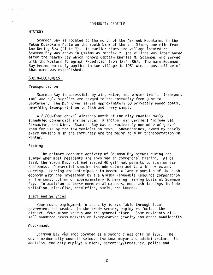
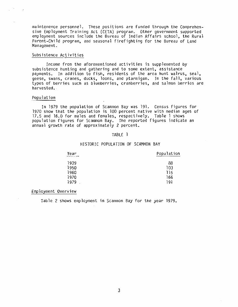
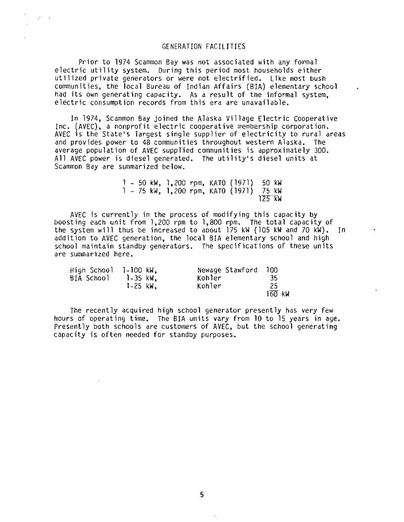
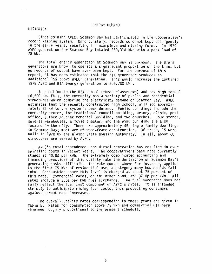
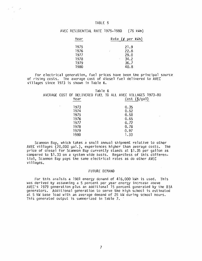
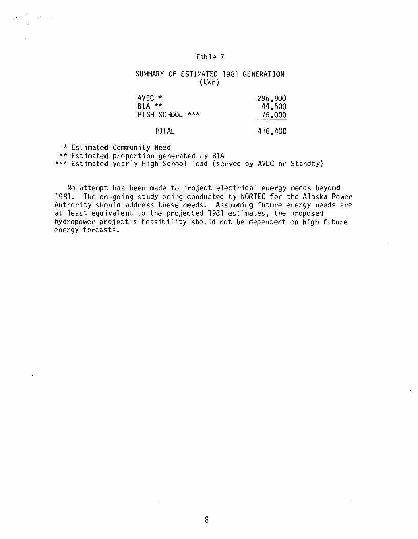
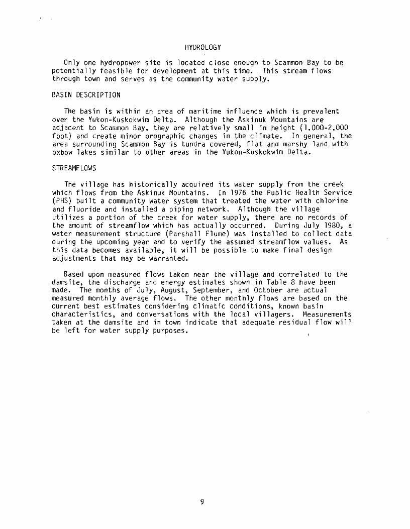
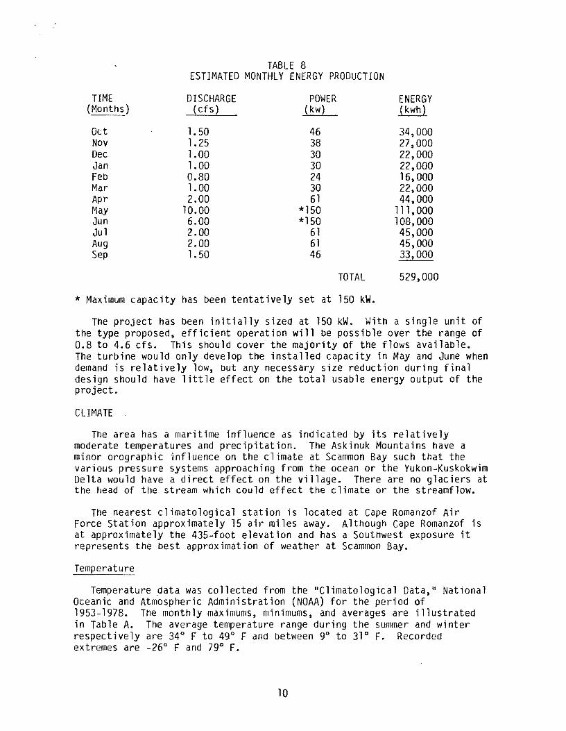
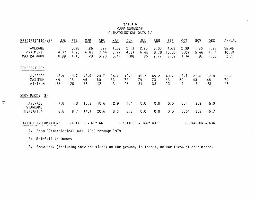
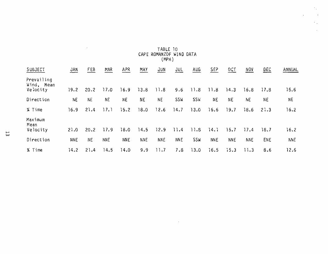
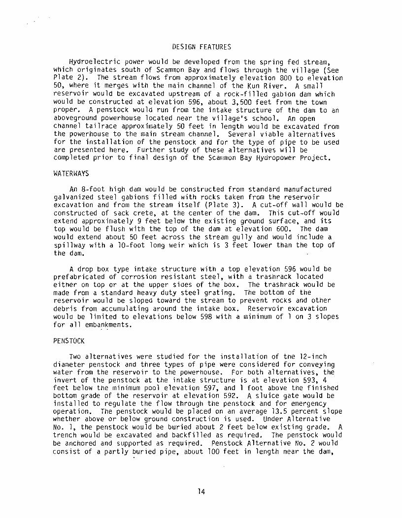
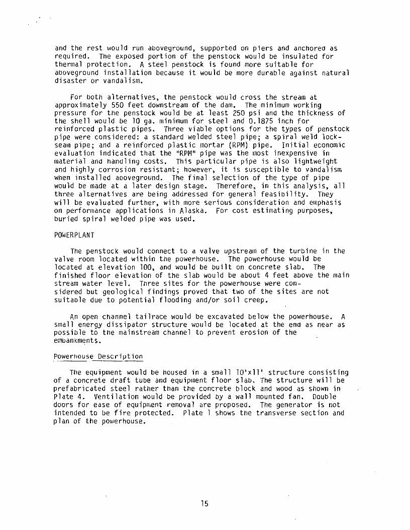
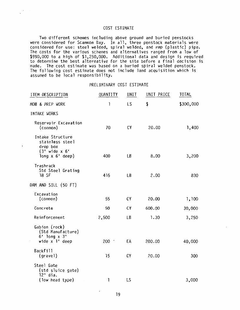
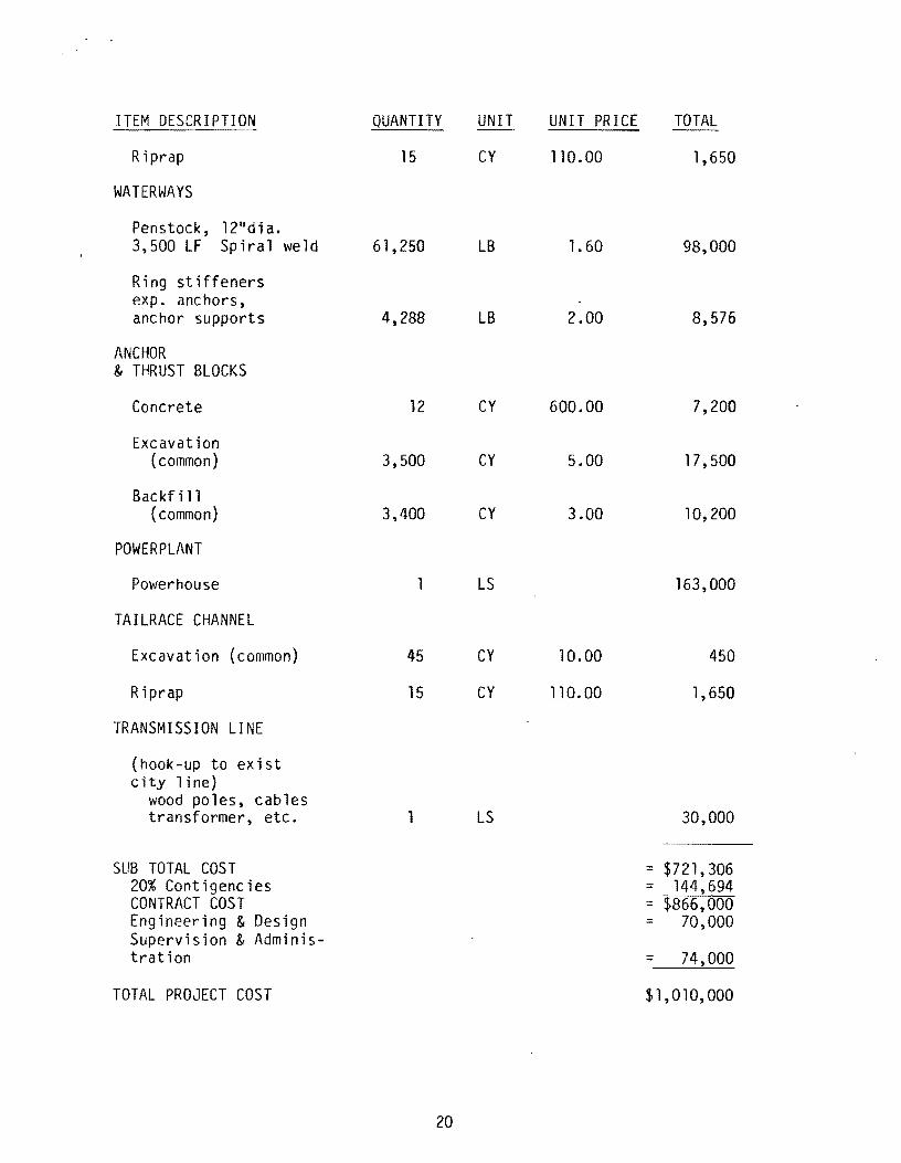
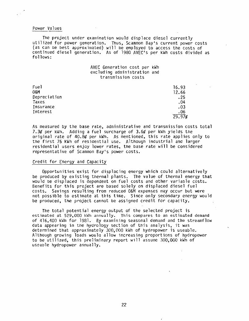
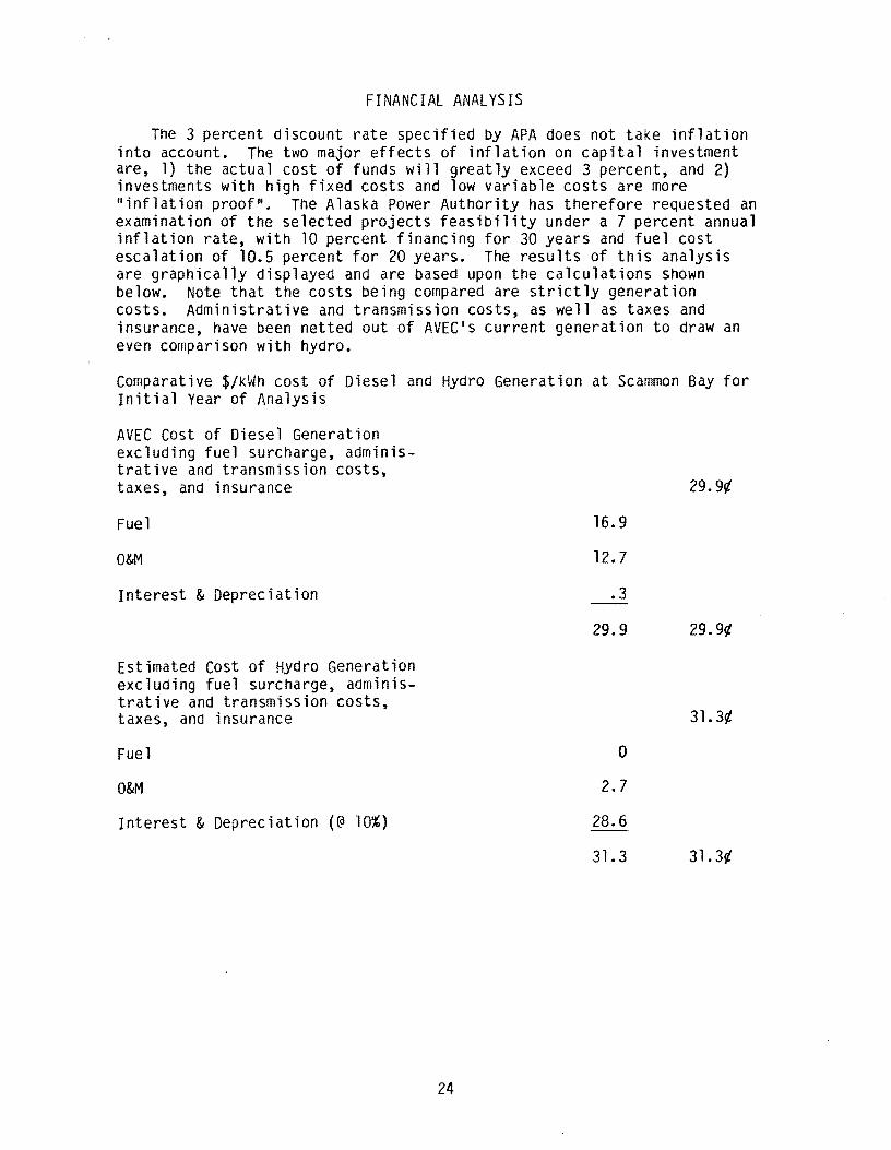
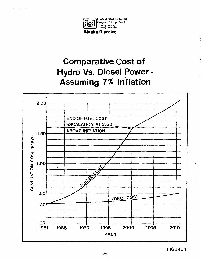
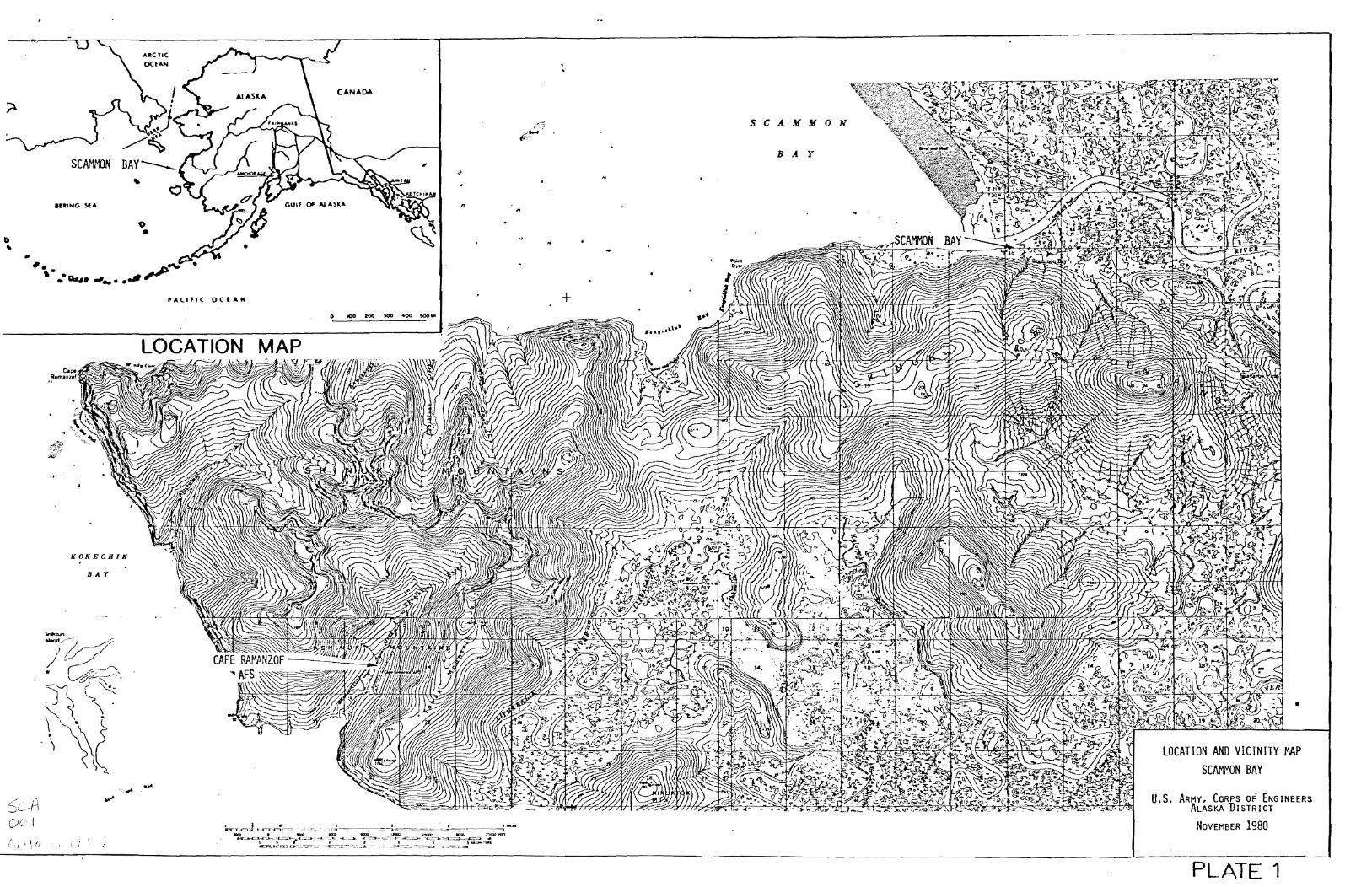
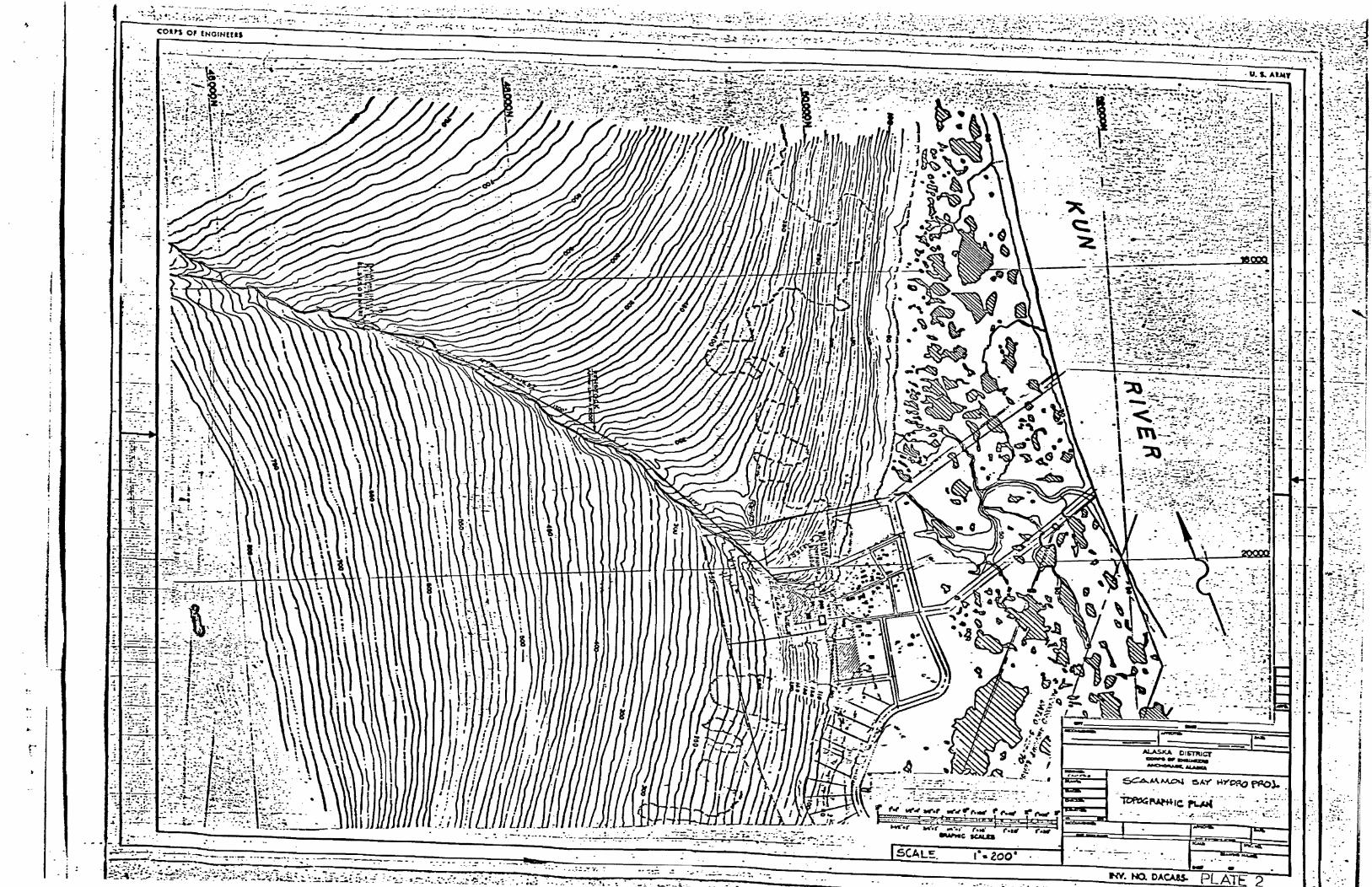
1
-- t -
~lt bull
0 ~ __
-- ishy- ~ ~
bull ~
S~lt (~~~~~ ~gt~ ~~ ~~~[~ -t-middot ~ bull i ~~ ~ bullbull ~ bull ~
- ----==--imiddot-r_=-_middot ~~ -~middot7~ ~~
-- - -- - - _--- _imiddot lt-
~ --shy-~ -- - -~ -
-
bullbullbull +i - ~-
__ ~i -
-
bull cons o INGINUU
bull
-
us ARNt PGINEEIt DISTRICT ALASICA coars ~ ---
~~~~~SCAMO) BAY t4YD20 ~- ~A~amp ar ~~
~~~ALT tf1-fet~ ~ eURl~ TfZ-fellSTDCt f~1 ~
-3
t
r
-
~
r------------~-----------_---------------~-----~--_---____ ~~_ _~~_ __ ~_ VALUE ENGINEERI CORPS OF ENGINEERS bull
D
~
I
bull II
c
bull
~
~ ~ ~
--
TRANSVERS SEw~ Sc4 -0
- - - -1ftiI- ~ ~
- ~ -
-_ t ~ bull - ~ bull
_ - ~ r_
~
-
-
~
1 ~ r 1 bull bull _ - 4~ bull ~
-J ~ - -
-
-
1-
-
--
--
~
c bull - -- --
- 1 ~
_ bull _ _ -J _
--lt bull
- -
bull -
V1LL INCREASE YOUR PROFITS
bull
- - -~
~
-
~ -
-
-~
~
~ ~
A bullbull
i~ ~~-J ~ ~
- ~ ~ ~ r~ ~~ ~ - -
1
~ -~
- ~ r
4 -
- -- ~ ~ -
~
UNIT RATING bull 110 kW
-
J-IEACgt 460 Fr
~ - ~
-L _
~
1
-
- -
- i
fIf
- u AmIY ENG~EER OMStON H P ~ IIlII1UCI __
SCAMMON BAY POWERHOUSI
-~ IIA1 ampUU -----------1
t==---1~VERSE SECTION AND PlAN
--middot----------------~--________ ~------middot----~-~r-------~Lt----~-------------~~--____ ~ ____ ~~--------~~~--~-------~~4
D
c
bull
A
- Preliminary Evaluation of Small Hydroelectric Power Development at Scammon Bay Alaska December 1980
- Summary13
- Table of Contents13
- Introduction13
- Community Profile13
- Generation Facilities13
- Energy Demand13
- Hydrology13
- Design Features13
- Environmental Impacts13
- Cost Estimate13
- Economic Analysis13
- Financial Analysis13
- Tables13
-
- Table 1 - Historic Population of Scammon Bay13
- Table 2 - Scammon Bay 1979 Employment by Industry13
- Table 313
- Table 4
- Table 5 - AVEC Residential Rate 1975-198013
- Table 6 - Average Cost of Delivered Fuel to all AVEC Villages 1973-8013
- Table 7 - Summary of Estimated 1981 Generation13
- Table 8 - Estimated Monthly Energy Production13
- Table 9 - Cape Romanzof Climatological Data13
- Table 10 - Cape Romanzof Wind Data13
-
- Figure 1 - Comparative Cost of Hydro vs Diesel Power assuming 7 inflation
- Plate 1 - Location and Vicinity Map
- Plate 2 - Topographic Plan
- Plate 3 - Alternatives
- Plate 4 - Powerhouse Transverse Section and Plan
-
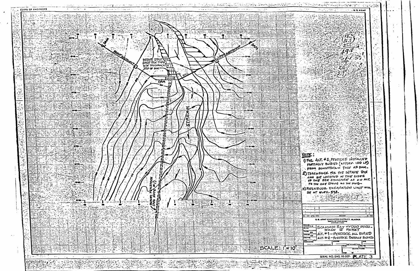
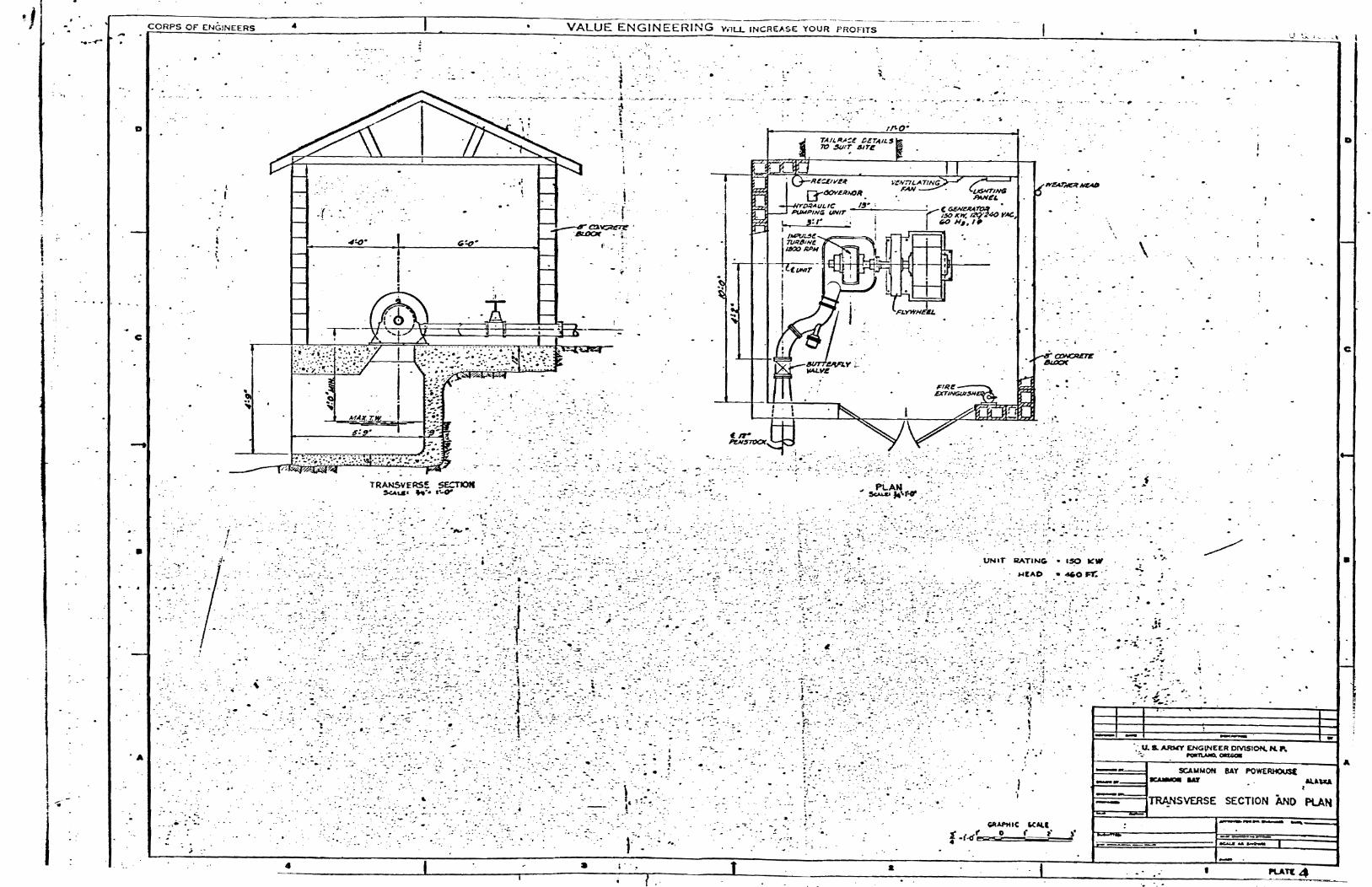