Preliminary Design Review: Hub Implementation Dan Edmunds, Wade Fisher, Yuri Ermoline, Philippe...
17
Preliminary Design Review: Hub Implementation Dan Edmunds, Wade Fisher, Yuri Ermoline, Philippe Laurens Michigan State University 01-Oct-2014
Transcript of Preliminary Design Review: Hub Implementation Dan Edmunds, Wade Fisher, Yuri Ermoline, Philippe...

Preliminary Design Review:Hub Implementation
Preliminary Design Review:Hub Implementation
Dan Edmunds, Wade Fisher, Yuri Ermoline, Philippe Laurens
Michigan State University01-Oct-2014

Outline: follow Hub Main functions Support for Daughter Cards
– ROD (& IPMC)
High-Speed Readout Data Streams– Hub’s main function: data path from FEXs to ROD
Un-managed Ethernet Switch– Gigabit Ethernet to Node Slots (et al) via Basic Interface
LHC Clock and TTC Data Stream distribution
01-Oct-2014 2

01-Oct-2014 3
400 pin MEG Array ( Exact location and orientation
of these connectors is TBD)
400 pin MEG Array
Zon
e 3
MP
T A
dapt
ers
IPMC (needs to be
rotated 90 degree for proper airflow)
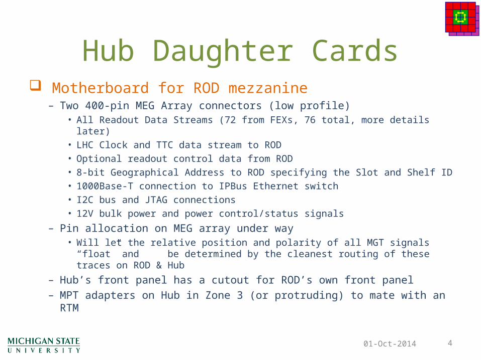
Hub Daughter Cards Motherboard for ROD mezzanine
– Two 400-pin MEG Array connectors (low profile)• All Readout Data Streams (72 from FEXs, 76 total, more details later)• LHC Clock and TTC data stream to ROD • Optional readout control data from ROD • 8-bit Geographical Address to ROD specifying the Slot and Shelf ID• 1000Base-T connection to IPBus Ethernet switch• I2C bus and JTAG connections• 12V bulk power and power control/status signals
– Pin allocation on MEG array under way• Will let the relative position and polarity of all MGT signals “float” and be
determined by the cleanest routing of these traces on ROD & Hub
– Hub’s front panel has a cutout for ROD’s own front panel– MPT adapters on Hub in Zone 3 (or protruding) to mate with an RTM
01-Oct-2014 4
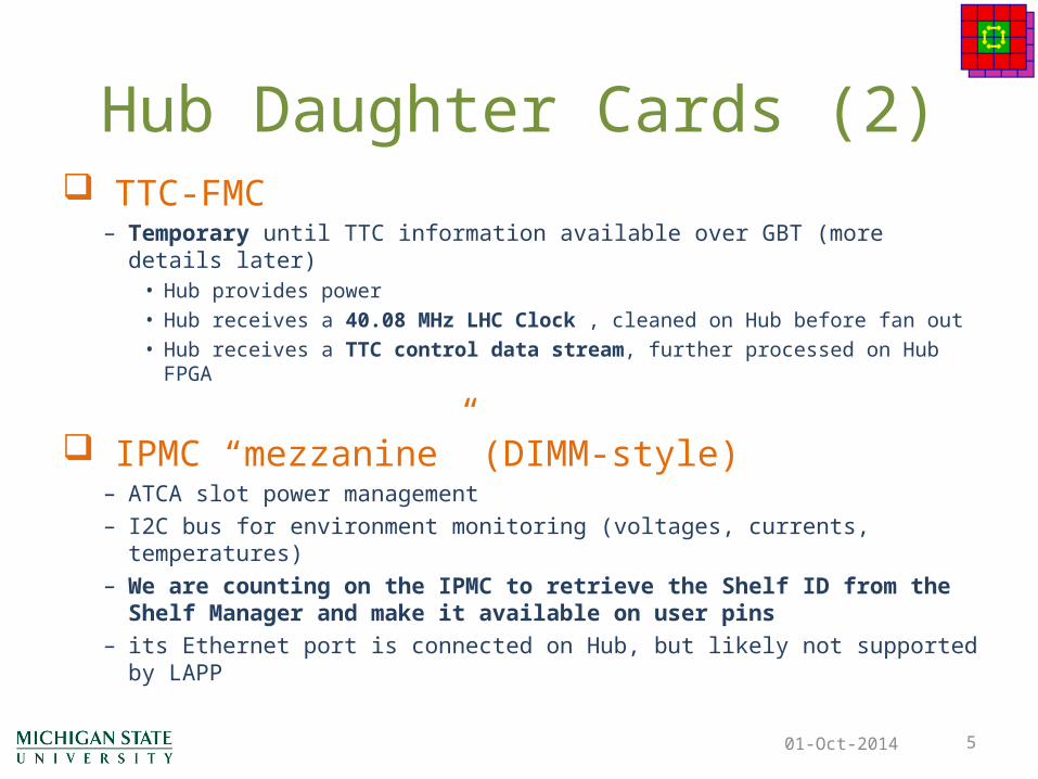
Hub Daughter Cards (2) TTC-FMC
– Temporary until TTC information available over GBT (more details later)• Hub provides power• Hub receives a 40.08 MHz LHC Clock , cleaned on Hub before fan out• Hub receives a TTC control data stream, further processed on Hub FPGA
IPMC “mezzanine” (DIMM-style)– ATCA slot power management– I2C bus for environment monitoring (voltages, currents, temperatures)– We are counting on the IPMC to retrieve the Shelf ID from the Shelf
Manager and make it available on user pins– its Ethernet port is connected on Hub, but likely not supported by LAPP
01-Oct-2014 5

01-Oct-2014 6

High-Speed Readout Data Streams 6x readout data streams from each FEX (6x12=72)
– High speed differential lines via Fabric Interface– Speed TBD: likely 6.4 or 9.6 Gbps
Hub fans out all readout streams from backplane – One copy sent to ROD, One copy to Hub FPGA
Optional readout data streams from Hub FPGAs– 2x data streams from local Hub FPGA– 2x data streams from other Hub FPGA (over Fabric Interf.) – Routed to ROD connector while ROD resources TBD
Both ROD & Hub FPGAs see all readout data01-Oct-2014 7

01-Oct-2014 8

01-Oct-2014 9

Ethernet Switch Un-managed 1Gb Ethernet switch on each Hub
– Up-link via front panel RJ45 (or multiple up-links)– Connection to each FEX via Basic Interface – Connection to other Hub FPGA via Service Interface– Connection to Hub ROD and Hub IPMC via front panel– New: No connection from Hub switch to ATCA Shelf Manager– Use 3 or 4 Broadcom or Marvel 6-8 port GE switch chips
Hub-1’s switch for Control subnet via IPbus Hub-2’s switch for IPMC subnet
– Subject to IPMC capabilities; New understanding: may remain unused
01-Oct-2014 10
New understanding :DCS has independent direct Ethernet connection to Shelf Manager
• For basic environment measurements (I, V, temp); I2C via IPMC and Zone 1 IPMB• Higher level measurements also available to DCS via IPbus

01-Oct-2014 11
X X
IPbusSubnet
IPMCSubnet

01-Oct-2014 12

LHC Clock and TTC Data Stream Receives and distributes the 40.08 MHz LHC Clock &
TTC control data stream– All 12x node slot FEXs– ROD & Hub FPGA on Hub-1 – ROD & Hub FPGA on Hub-2 – via Fabric Interface– TTC data stream format defined elsewhere
Only Hub-1 distributes LHC Clock & TTC Data Stream– Hub-2 circuitry is just as capable; but not used in base plan
Optional merging of readout flow control information from RODs of both Hub-1 &Hub-2 – Optional feature, may not be needed
01-Oct-2014 13

LHC Clock and TTC Data Stream (2) Prototype stage (2015): use TTC-FMC
– We now understand: no benefit by waiting for FELIX FMC – But need to secure enough TTC-FMCs for prototype stage
• More details later on
01-Oct-2014 14
New since PDR document: Ready for future TTC input media (201?): GBT fiber
– Add one SFP transceiver on Hub with (at least) its receiver section connected to a GTH input on the Hub FPGA.
– Firmware provided to recover LHC clock and TTC data stream

01-Oct-2014 15
LHC Clock and TTC Data Stream (3)
01-Oct-2014 16
New: Alternate Proposal TTC-FMC is a temporary and “bulky” solution
– Only used during early tests – FMC footprint is and will remain unusable for anything else
Board space for Hub’s own functionality is scarce resource
Proposal: No TTC-FMC on Hub (i.e. only SFP for GBT) Still always provide a clean 40.08 MHz clock to whole
crate Hub FPGA Firmware would emulate TTC data stream
– Minimum: L1Accept and Beam Crossing Reset (what else?)– Controlled via IPbus, e.g. L1A “on demand” or “prescaled”
Is this sufficient for all tests of FEXs & ROD at prototype stage? Is such emulation sufficient until GBT input available?
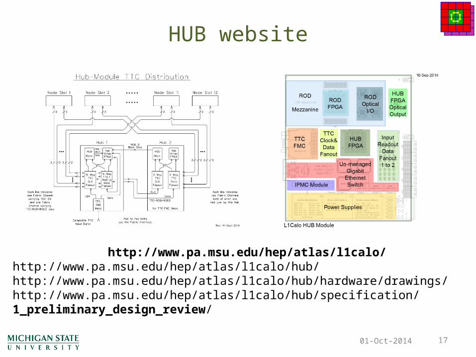
HUB website
01-Oct-2014 17
http://www.pa.msu.edu/hep/atlas/l1calo/http://www.pa.msu.edu/hep/atlas/l1calo/hub/http://www.pa.msu.edu/hep/atlas/l1calo/hub/hardware/drawings/http://www.pa.msu.edu/hep/atlas/l1calo/hub/specification/1_preliminary_design_review/