Preface - sunfounder.com€¦ · Preface . About SunFounder . SunFounder is a technology company...
50
Preface About SunFounder SunFounder is a technology company focused on Raspberry Pi and Arduino open source community development. Committed to the promotion of open source culture, we strive to bring the fun of electronics making to people all around the world and enable everyone to be a maker. Our products include learning kits, development boards, robots, sensor modules and development tools. In addition to high quality products, SunFounder also offers video tutorials to help your own project. If you have interest in open source or making something cool, welcome to join us! Visit www.sunfounder.com for more! About the Kit The Q250/SF250 quadcopter is tailored for the hobbyists for FPV flying. It runs the OpenPilot firmware of the flight controller and the electronic speed controller. This kit is designed to meet the hobbyists’ higher requirement of flying the aircraft, featuring stability, flexibility and agility. You can realize a stable flight in a small space or a rapid 3D flight based on your own configuration and parameter setting. In this book, we will show you how to configure the wizard of CC3D. In addition, we have also provided the videos about how to assemble and fly the Q250 and SF250 quadcopters for you. You can check them under VIDEO on our website. Free Support If you have any TECHNICAL questions, add a topic under FORUM section on our website and we'll reply as soon as possible. For NON-TECH questions like order and shipment issues, please send an email to [email protected]. You're also welcomed to share your projects on FORUM. Copyright Notice All contents including but not limited to texts, images, and code in this manual are owned by the SunFounder Company. You should only use it for personal study, investigation, enjoyment, or other non-commercial or nonprofit purposes, under the related regulations and copyrights laws, without infringing the legal rights of the author and relevant right holders. For any individual or organization that uses these for commercial profit without permission, the Company reserves the right to take legal action. SunFounder
Transcript of Preface - sunfounder.com€¦ · Preface . About SunFounder . SunFounder is a technology company...

Preface
About SunFounder
SunFounder is a technology company focused on Raspberry Pi and Arduino open source
community development. Committed to the promotion of open source culture, we strive to
bring the fun of electronics making to people all around the world and enable everyone to
be a maker. Our products include learning kits, development boards, robots, sensor
modules and development tools. In addition to high quality products, SunFounder also offers
video tutorials to help your own project. If you have interest in open source or making
something cool, welcome to join us! Visit www.sunfounder.com for more!
About the Kit
The Q250/SF250 quadcopter is tailored for the hobbyists for FPV flying. It runs the OpenPilot
firmware of the flight controller and the electronic speed controller. This kit is designed to
meet the hobbyists’ higher requirement of flying the aircraft, featuring stability, flexibility and
agility. You can realize a stable flight in a small space or a rapid 3D flight based on your own
configuration and parameter setting.
In this book, we will show you how to configure the wizard of CC3D. In addition, we have
also provided the videos about how to assemble and fly the Q250 and SF250 quadcopters
for you. You can check them under VIDEO on our website.
Free Support
If you have any TECHNICAL questions, add a topic under FORUM section on our
website and we'll reply as soon as possible.
For NON-TECH questions like order and shipment issues, please send an email to
[email protected]. You're also welcomed to share your projects on FORUM.
Copyright Notice
All contents including but not limited to texts, images, and code in this manual are owned
by the SunFounder Company. You should only use it for personal study, investigation,
enjoyment, or other non-commercial or nonprofit purposes, under the related regulations
and copyrights laws, without infringing the legal rights of the author and relevant right
holders. For any individual or organization that uses these for commercial profit without
permission, the Company reserves the right to take legal action.
SunFou
nder

Contents
1. Overview ...................................................................................................................................... 1
For Q250 ....................................................................................................................................... 1
For SF250 ...................................................................................................................................... 2
For SF250 Assembled Kit (with Radio Transmitter) .................................................................. 3
2. Connect the Receiver ............................................................................................................... 4
CC3D Flight Controller ............................................................................................................... 4
Connect to the Receiver .......................................................................................................... 5
For PWM Mode: ................................................................................................................... 5
For PPM Mode: .................................................................................................................... 6
For SBUS Mode: .................................................................................................................... 7
About the Radio Transmitter ..................................................................................................... 7
3. CC3D Software Debugging .................................................................................................... 10
Installing the Ground Control Station (GCS) ......................................................................... 10
Plug in the CC3D Flight Control .............................................................................................. 11
Configuring the Wizard of CC3D ........................................................................................... 14
Calibrating the Motor Output................................................................................................. 19
Configuring the Radio Transmitter ......................................................................................... 24
Modifying the RX Input Parameters ....................................................................................... 31
PWM Mode ........................................................................................................................ 32
PPM Mode .......................................................................................................................... 33
SBUS Mode ......................................................................................................................... 35
Check the Flight Mode ............................................................................................................ 35
Calibrating the Aircraft ............................................................................................................ 36
Setting Parameters Manually .................................................................................................. 38
PWM Mode ........................................................................................................................ 38
PPM Mode .......................................................................................................................... 41
SBUS Mode ......................................................................................................................... 45
Save the Settings ...................................................................................................................... 47
SunFou
nder

1
1. Overview
This instruction manual applies to the aircraft kits including the Q250 kit, SF250 components
kit, and SF250 assembled kit (with radio transmitter).
Since the Q250 and SF250 kit are provided in components, you need to mount them yourself.
For different aircrafts, check the respective assembly tutorials below.
For Q250
Visit our website www.sunfounder.com, click VIDEO, scroll down to Aircraft Model and find
Q250. You can see 6 videos there on the page, including a basic introduction one and 5
detailed tutorials. The tutorial videos are marked with numbers in order. Aircraft assembly
requires great carefulness and patience, so please follow the steps in the video closely.
SunFou
nder

2
For SF250
On our website, go to VIDEO -> Aircraft Model -> SF250. You can see 6 videos including a
basic introduction one and detailed tutorials which are marked with numbers in order.
Aircraft assembly is a task that requires carefulness and patience, so please follow the steps
in the video for operation.
SunFou
nder

3
For SF250 Assembled Kit (with Radio Transmitter)
For the SF250 assembled kit, most of the components have been assembled except the
propellers and the battery before arriving at your doorstep. Please finish the assembly by
following the tutorial in www.sunfounder.com -> WIKI -> Drones/Model Aircrafts->CC3D ->
SunFounder 250+Radiolink T8FB Remote Controller(Assembled).
The receiver included is a PWM mode one with firmware burnt. If the firmware is missing due
to an aircraft collision or some other reasons, you need to reburn it; please refer to 3. CC3D
Software Debugging.
SunFou
nder

4
2. Connect the Receiver
The wire connection for the PWM Mode is mentioned in the video, but the wiring differs for
various receivers in different modes, so you need to adapt it to the actual situation. First let's
check the pins of the CC3D flight controller.
CC3D Flight Controller
The pins of CC3D flight controller is as shown below. When wiring, you should be clear about
the pins’ name and connect them correctly, or a short circuit may happen.
SunFou
nder

5
Connect to the Receiver
The CC3D flight controller supports three modes: PWM, PPM, and SBUS. Thus as long as your
receiver supports one of these modes, it works with this kit. The wiring for three modes is
described below.
For PWM Mode:
Prepare eight wires for a PWM mode receiver, and connect the receiver and the flight
controller as shown below. You can modify the corresponding channel in software
debugging part.
Flight Controller Receiver
GND GND
PWR VCC
1 CH1
2 CH2
3 CH3
4 CH4
5 CH5
6 CH6
SunFou
nder

6
For PPM Mode:
Flight Controller Receiver
GND GND
PWR VCC
6 PPM
For PPM mode, since GND, PWR and CH1 are connected together, we need to connect
the 3pin cable to other position, and then connect CH6 to PPM(CH2).
SunFou
nder

7
For SBUS Mode:
Flight Controller (Main Port) Receiver
GND GND
VCC VCC
TX N/A
RX SBUS
About the Radio Transmitter
Since a radio transmitter will be used in software debugging, let’s first learn something about it now.
For more details, please refer to the transmitter’s user manual.
Talking of radio transmitter control, here a term is involved: "channel", meaning how many
types of movement the copter can make by the radio transmitter control. For example, up
and down can be counted one channel. If the radio transmitter control can only control
the copter to fly up and down, it's called one channel.
For a quadcopter, at least four channels are needed, namely, up-down, right-left, forward-
backward, and clockwise-counterclockwise rotation. The corresponding channels are
throttle (up-down), roll (right-left), pitch (front-back) and yaw (clockwise-counterclockwise
rotation). If you want more functions, more channels are required.
SunFou
nder

8
Before applying the radio transmitter, you need to know there are two different types of
radio transmitter. They are different in the position of throttle – left (what we provided in this
kit) and right. The throttle controls the motor speed. The higher you push it, the motor rotates
faster, and the quadcopter flies higher, and vice versa. It is quite easy to tell the throttle. Try
to pull the two rocker arms. The one that will not restore to the middle is the throttle rocker.
Radio Transmitter (left hand throttle)
Radio Transmitter (right hand throttle)
See the figure below for the throttle type.
Mode 1 (Throttle left) Mode 2 (Throttle right)
The four rocker channels are Throttle, Rudder, Elevator, and Aileron, which are Throttle, Yaw,
Pitch, and Roll respectively in the software. The mapping relationship is as shown below:
Throttle Throttle
Rudder Yaw
Elevator Pitch
Aileron Roll
SunFou
nder

9
Next, let’s move on to software debugging.
SunFou
nder
10
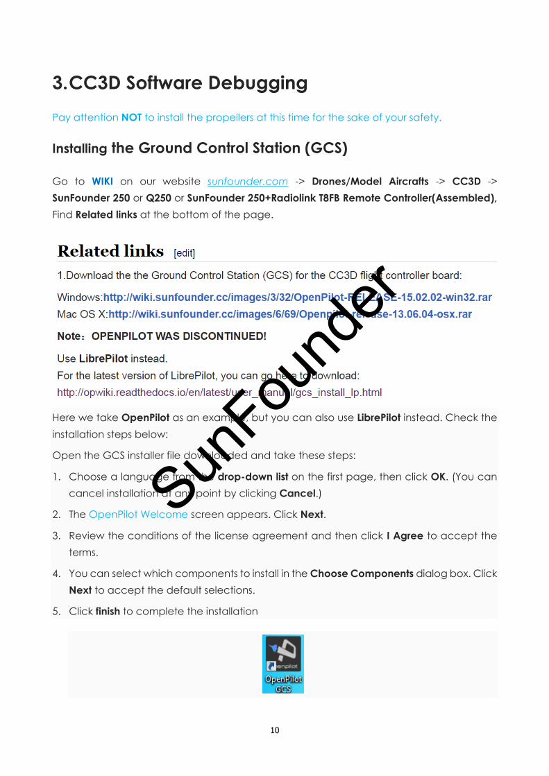
3. CC3D Software Debugging
Pay attention NOT to install the propellers at this time for the sake of your safety.
Installing the Ground Control Station (GCS)
Go to WIKI on our website sunfounder.com -> Drones/Model Aircrafts -> CC3D ->
SunFounder 250 or Q250 or SunFounder 250+Radiolink T8FB Remote Controller(Assembled),
Find Related links at the bottom of the page.
Here we take OpenPilot as an example, but you can also use LibrePilot instead. Check the
installation steps below:
Open the GCS installer file downloaded and take these steps:
1. Choose a language from the drop-down list on the first page, then click OK. (You can
cancel installation at any point by clicking Cancel.)
2. The OpenPilot Welcome screen appears. Click Next.
3. Review the conditions of the license agreement and then click I Agree to accept the
terms.
4. You can select which components to install in the Choose Components dialog box. Click
Next to accept the default selections.
5. Click finish to complete the installation
SunFou
nder

11
Plug in the CC3D Flight Control
Connect the CC3D flight controller to computer with the Micro USB Cable included, and
you can see the Power LED lights up and stay brighten constantly, while the Status LED blinks.
The driver installation will take some minutes; a reminder of failing to install may pop up as
shown below, and you can just ignore it - the installation result in Device Manager shall
prevail.
Open Device Manager. If you see CopterControl Virtual COM Port (COMxx) (the number
depends on your actual situation), it indicates the flight controller has been recognized by
the computer.
If you see the CopterControl with a yellow exclamation mark!in Other devices:
SunFou
nder

12
There are two possibilities:
1) OpenPilot or LibrePilot GCS is not installed yet;
2) The driver failed to install.
Right-click CopterControl, and click Update Driver Software…
Select Browse my computer for driver software.
SunFou
nder

13
Click Browse to enter the installation path of OpenPilot (or LibrePilot), and select the driver
folder, then click Next.
When the installation is all done, click close to exit. Then you can see the flight controller has
been recognized by the computer.
SunFou
nder

14
Later during the application, sometimes it may happen that the device cannot be
recognized. Don’t worry, just try to replug the USB cable, or reburn the firmware.
Configuring the Wizard of CC3D
Ensure the CC3D flight controller is kept connected to the computer, and double-click to
open the GCS just installed. The TX and RX data at bottom indicates the flight controller’s
connecting status. If they are both in grey, it means the flight controller is not connected.
Just replug to try.
Click Vehicle Setup Wizard and enter the interface of configuring the wizard as shown
below:
SunFou
nder

15
On the interface of configuring the wizard, there is a red mark reminding you to disassemble
the propeller blades before configuring the wizard in case of any accidents. Then click Next
to enter the interface of firmware upgrading.
It will prompt you that the version of the firmware should be consistent with that of the GCS.
For the first time of configuring, you're suggested to upgrade the firmware. Take the
following steps:
Unplug the battery and USB cable from OpenPilot to ensure the CC3D flight control board
is powered down and no LED is on.
Click Upgrade
Plug the USB cable when the bar starts running. Then the GCS will automatically write the
latest firmware onto the board.
SunFou
nder

16
After writing is done, then click Next to configure the receiver of the remote-control system.
Select the corresponding mode according to your receiver’s wiring. Here we take PWM
mode as an example.
Click Next. Choose the type of vehicle the OpenPilot controller board is going to be used
with. Choose Multirotor among the four types of vehicles - Multirotor, Helicopter, Fixed wing
and Surface.
SunFou
nder

17
Then, choose the multirotor type. There are several choices provided on the drop-down list
of the multirotor type. Choose Quadcopter X.
Click Next. Choose Rapid ESC.
SunFou
nder

18
Now you can see all the settings you just completed displayed on the interface.
Click Next to go to the interface of calibrating the sensor. Be careful to ensure that the
vehicle is really level before calibration to avoid any error.
SunFou
nder

19
For hardware configuration, if you don't remember the options or are not sure about the
settings, just leave the default option selected.
Calibrating the Motor Output
Enter the interface of output calibration of the motor. Pay attention to disassemble the
propellers before switching on power.
Follow the instructions on the page to operate: DO NOT connect the battery right now; tick
all the precautions first (reality should also meet the conditions), click Start and connect the
battery to the aircraft, and then click Stop after hearing a beep from the ESC. Finally,
disconnect the battery, and then click Next.
SunFou
nder

20
Click Next.
SunFou
nder

21
The output calibration means setting the neutral rate for the motor. Follow the steps below:
Step 1: Connect the battery to the aircraft.
Step 2: Press the Start button below and slide the slider to the right until the motor starts to
spin.
Step 3: Click Stop. When the motor stops, press Start again to see whether the motor can
start itself. Slide the sliders to the left or right to set the critical point of the motor to spin.
Step 4: Please pay attention to the rotation direction of the motor. Ensure the motors are
spinning in the correct direction as shown in the diagram. Otherwise, swap any two wires of
a motor to change the direction.
Since the output calibration of the Motor 2, 3 and 4 is the same as the Motor 1, just set their
neutral rate in the same way as setting the Motor 1.
Note: Pay attention NOT to make the motor spin too slowly because it will give out much
heat at the critical point, which may damage the motor.
SunFou
nder

22
After setting, select the type of your air frame. For a Q250 quadcopter, choose Current
Tuning. And for SF250, please choose QAV250. Then click Next.
Click Save to save the configuration directly to your OpenPilot controller.
SunFou
nder

23
After saving, there will be an interface of rebooting your controller. Just wait for a while.
SunFou
nder

24
Configuring the Radio Transmitter
During the configuration of the radio transmitter, the default option is that the GCS of the
CC3D disables the unlocking of the throttle. You'd better check whether the throttle is
locked before configuration to avoid any damage during the configuration caused by
having forgot to unload the battery. Click Transmitter Setup Wizard to enter the interface of
configuring the radio transmitter.
You can also click Finish and choose another way to configure the radio transmitter like
clicking Configuration->Input->Start Transmitter Setup Wizard as shown below. SunFou
nder

25
Pay attention to the points below before configuration:
1) Keep the receiver correctly connected to the flight controller which is powered by a
battery. If not, follow steps in 2. Connect the receiver to connect.
2) Switch on the radio transmitter; make sure your transmitter works well with the receiver,
and they can be paired.
After entering the interface of configuring the radio transmitter, follow the prompt on the
screen to pull the rockers. You can cancel or return to the last step at any time during the
configuration. SunFou
nder

26
Next, choose the type of transmitter of the radio transmitter between Acro and Multicopter.
Acro is suitable for fixed wing aircraft and quadcopter. Therefore, here choose Acro.
Next, select the transmitter mode of the radio transmitter. Here are two options: throttle-left
mode and throttle-right mode. The default one is the throttle-left mode namely Mode 2 as
below: Throttle and Rudder on the left, Elevator and Aileron on the right.
SunFou
nder

27
Click Next, follow the prompts on the screen to calibrate the throttle, aileron, elevator, and
rudder respectively.
Notes:
Firstly: When you move the throttle stick for the first time, if it is moved all the time even when
you move other channel sticks, you should follow these steps to check.
1) Check whether the receiver is correctly connected to the CC3D board. Pay attention
to the wire order and not to inversely connect the wires.
2) Check whether the power supply of the CC3D is turned on. Only the USB port for
CC3D is not enough to power the receiver.
3) Check whether the receiver and the transmitter are matched successfully. Press and
hold the button on the receiver until the LED onside blinks, and then the LED will
brighten constantly, indicating the receiver is matched successfully.
4) Check the receiver’s mode. You need to be aware of the color of the LED on the
receiver for each mode. Press the button twice quickly to shift modes.
If after you move one stick of Throttle, Pitch, Roll, and Yaw, the stick on OpenPilot still moves,
it means the corresponding channel has not been configured well. Then click Back, and
repeat the previous steps to check.
SunFou
nder

28
Then, calibrate the flight mode. A 3-way auxiliary channel would be better to set. Note
down the aux channel for flight mode setting, since we will use it later.
Configure Accessory 0, Accessory 1 and Accessory 2. If you don’t want to do that, just click
Next/Skip.
SunFou
nder

29
After all the configuration, keep all the channel switched at neutral. Click Next.
Please move all controls to their maximum on both directions to check whether all channels
have been configured well. You should see the stick in OpenPilot moves as the real stick
does. If not, please click Back to configure that channel again.
SunFou
nder

30
Based on the instructions, pull the throttle, aileron, elevator, or rudder or toggle the mode
switch to check whether it moves in the same direction as the stick actually does.
For example, when you move the Throttle stick from lowest to highest on the transmitter, if
the throttle stick on the OpenPilot also moves in the same way, it’s OK; but if it move from
highest to lowest, it's got reversed. Then just tick the Throttle in the software and there is no
need to configure it on the radio transmitter.
SunFou
nder

31
Until now, all the configuration of the channels is completed. Click Save and then enter the
configuration of unlocking the radio transmitter.
During configuration of the radio transmitter, by default the throttle is locked. You can
define the method to unlock it in the way you like. Next, set the time of receiving no signal
to automatically lock the throttle. 30s is set by default. Usually, we unlock the throttle through
Throttle off (to the lowest) and Yaw Right.
Finally, Click Save.
Modifying the RX Input Parameters
Click RC Input, and under the tab you will see the parameters for all channels: Type, Number,
Min and Max values, and Neutral etc. Sun
Found
er

32
Some parameters are not reasonably set by default, which may cause failure in unlocking
the aircraft, thus we should modify these parameters prior to flying.
PWM Mode
Click Output on the menu column at the left side. Neutral is the critical point of the motor to
spin that you configured previously. So, we can know the highest critical point of the four
motors is 1088.
Click Input, and set the Min, Neutral and Max values for all channels.
Min: the minimum value of the channel.
SunFou
nder

33
Neutral: the threshold value of the channel. The Neutral for the throttle should be set
greater than that for four motors (1088), and about 50 greater than the Min value, in case
the aircraft takes off when we just slightly pull the throttle; and it leaves enough throttle
ascending space, which would be easier to operate for entry-level hobbyists. Set all
others Neutral values to 1500 (median for Min and Max).
Max: the maximum value of the channel.
Move the channel sticks. If the channel value slider is toggled reversely, just tick Reversed.
For instance, when you move the Pitch stick from bottom to top, if the channel value slider
is toggled from right to left at the same time, it indicates it is reversed. Thus you should tick
the box Reversed after Pitch. Then click Save after modifying.
PPM Mode
Click Output on the menu column at the left side. Neutral is the critical point of the motor to
spin that you configured previously. So, we can know the highest critical point of the four
motors is 1089.
SunFou
nder

34
Click Input, and set the Min, Neutral and Max values for all channels.
Min: the minimum value of the channel.
Neutral: the threshold value of the channel. The Neutral for throttle should be set greater
than that for four motors (1089), and about 50 greater than the Min value, in case the
aircraft takes off when we just slightly pull the throttle; and it leaves enough throttle
ascending space, which would be easier to operate for entry-level hobbyists. Set all
others Neutral values to 1500 (median for Min and Max).
Max: the maximum value of the channel.
SunFou
nder

35
Move the channel sticks. If the channel value slider is toggled reversely, just tick Reversed.
For instance, when you move the Pitch stick from bottom to top, if the channel value slider
is toggled from right to left at the same time, it indicates it is reversed. Thus you should tick
the box Reversed after Pitch. Then click Save after modifying.
SBUS Mode
Set the Min value of all channels to 200, Max to 1800. Then the Neutral of Throttle to 400,
and others to 1000. Then click Save.
The Neutral value of Throttle is the threshold of motor to start spinning, thus we set it to 100-
300 greater than the Min value to start the aircraft safely.
Move the channel stick. If the channel value slider is toggled reversely, just tick Reversed.
For instance, when you move the Pitch stick from bottom to top, if the channel value slider
is toggled from right to left, it indicates it is reversed. Thus we should tick the box Reversed
after Pitch. Then click Save after modifying.
Check the Flight Mode
Click Flight Switch Mode. There are three flight modes usually:
1) Stabilized 1: Self-stabilization. In this mode, you can only control the throttle to fly the
aircraft. This mode is suitable for beginners.
2) Stabilized 2: Semi-self-stabilization. In this mode, you can control the channel of YAW
and Thrust to adjust horizontal direction and throttle.
3) Stabilized 3: Manual. In this mode, the Roll, Pitch, Yaw, and Thrust channel can all be
controlled, which may be not so easy to operate.
SunFou
nder

36
Move the aux channel for flight mode setting, and you can see the Slider is toggled to the
corresponding position (Pos. 1, Pos. 2, Pos. 3…). For beginners, DO select Pos. 1. You can try
Pos. 2 or higher level when you've mastered the basic control and can handle higher ones.
Note: The figure below is to show you that you can move the aux channel to select the flight
mode, which does NOT mean to select Pos. 2. For beginners, please select Pos. 1.
Click Save.
Calibrating the Aircraft
Actually we have configured the aircraft previously and you can skip this step. But if the
aircraft keeps tilting to one side during the flight, you can take these instructions.
SunFou
nder

37
Click FlightData, and check whether the horizontal line is in parallel with the yellow line or
not. If yes, the calibration is ok; otherwise, follow the instructions below to operate.
Place the aircraft on a leveled surface, click Altitude, then Level to calibrate. When the
progress bar goes to 100%, click Save.
SunFou
nder

38
Click FlightData again, and then you can see parallel lines now.
So you've finished the debugging. Now, let’s mount the propellers, and unlock the aircraft
to check how it flies well.
Note: If an aircraft bumping happens, the setting parameters will change, thus you need to
follow 3. CC3D Software Debugging to configure again.
Setting Parameters Manually
If the aircraft cannot be unlocked and controlled after you take the steps in Configuring the
Radio Transmitter, you can set the parameters manually. Or just skip the settings wizards,
and set them manually.
PWM Mode
Step 1: Ensure the receiver has been toggled to the PWM mode and connected correctly,
and power on the aircraft and radio transmitter with a battery.
Step 2: Open Openpilot, click Input at left side, and then select PWM for all channels under
Type, and set Chan 1-Chan 5 under Number correspondingly. Throttle, Roll, Pitch, and Yaw
are main channels, while FlightMode is an aux channel to set the flight mode. To realize
basic flight needs, you only need to set these 5 channels. Then click Save.
SunFou
nder

39
Step 3: Move the Throttle stick to check the channel value status on the OpenPilot.
If the Pitch changes when you move the Throttle stick, just exchange the channel of Pitch
and Throttle on the interface, then click Save. Now Throttle is Chan3, while Pitch is Chan1.
Step 4: Move the Elevator stick.
If the Roll changes when you move the Pitch stick, similarly just exchange the two channels,
then click Save. Now Roll is Chan1, while Pitch is Chan2.
SunFou
nder

40
Step 5: Move the Aileron stick.
If the Roll channel value changes, no need to modify its channel. But if the Yaw changes
when you move the Roll stick, just exchange the channel Chan4 and Chan5.
Step 6: Move the Rudder stick.
Then you may see Yaw channel value changes, no need to modify then. Otherwise swap
the channel values with another channel.
Step 7: Since only CH2 to CH6 are connected of the receiver, you can set FlightMode to
Chan5 first, and move all the aux channels to see which the slider is toggled. Then that one
is Chan5. Note down the position of the aux channel to set the aircraft flight mode later.
Save the setting.
Step 8: Check four motors’ Neutral values.
Click Output on the menu column at the left side. Neutral is the critical point of the motor to
spin that you configured previously. So, we can know the highest critical point of the four
motors is 1088.
SunFou
nder

41
Step 9: Click Input, and set the Min, Neutral and Max values for all channels.
Min: the minimum value of the channel.
Neutral: the threshold value of the channel. The Neutral for throttle should be set greater
than that for four motors (1088), and about 50 greater than the Min value, in case the
aircraft takes off when we just slightly pull the throttle; and it leaves enough throttle
ascending space, which would be easier to operate for entry-level hobbyists. Set all
others Neutral values to 1500 (median for Min and Max).
Max: the maximum value of the channel.
Move the channel stick. If the channel value slider is toggled reversely, just tick Reversed.
For instance, when you move the Pitch stick from bottom to top, if the channel value slider
is toggled from right to left at the same time, it indicates it is reversed. Thus you should tick
the box Reversed after Pitch. Then click Save after modifying.
PPM Mode
Step 1: Ensure the receiver has been toggled to the PPM mode and the receiver wiring has
been connected correctly, power on the aircraft and radio transmitter with a battery.
Step 2: Open OpenPilot, and click Input at left side, then select PPM for all channels under
Type, and set Chan1 –Chan5 under Number correspondingly (Throttle, Roll, Pitch, and Yaw
are main channels, while FlightMode are aux channel to set the flight mode. To realize basic
flight needs, we only need to set these 5 channels. Then click Save.
SunFou
nder

42
Step 3: Move the Throttle channel stick to check the channel value status on the
OpenPilot.
If the Pitch changes when you move the Throttle channel stick, just exchange the channel
of Pitch and Throttle, then click Save. Now Throttle is Chan3, while Pitch is Chan1.
Step 4: Move the Elevator channel stick.
If the Roll changes when you move the Pitch channel stick, just exchange the channel of
Roll and Pitch, then click Save. Now Roll is Chan1, while Pitch is Chan2.
SunFou
nder

43
Step 5: Move the Aileron channel stick.
If the Roll channel value changes, no need to modify its channel. If the Yaw changes
when you move the Roll stick, just exchange the channel Chan4 and Chan5.
Step 6: Move the Rudder channel stick.
Then you may see Yaw channel value changes, no need to modify then.
Step 7: Since we only connect from CH2 to CH6 in receiver wiring part, you can set
FlightMode to Chan5, and move the aux channel to see whether the slider is toggled or not.
If yes, the corresponding one is Chan5. Remember the aux channel for the aircraft flight
mode setting.
Save the setting.
Step 8: Check four motors’ threshold values.
Click Output on the menu column at the left side. Neutral is the critical point of the motor
to spin that you configured previously. So, we can know the highest critical point of the
four motors is 1089. SunFou
nder

44
Click Input, and set the Min, Neutral and Max values for all channels.
Min: the minimum value of the channel.
Neutral: the threshold value of the channel. The Neutral for throttle should be set greater
than that for four motors (1089), and about 50 greater than the Min value, in case the
aircraft takes off when we just slightly pull the throttle; and it leaves enough throttle
ascending space, which would be easier to operate for entry-level hobbyists. Set all
others Neutral values to 1500 (median for Min and Max).
Max: the maximum value of the channel.
SunFou
nder

45
Move the channel stick. If the channel value slider is toggled reversely, just tick Reversed.
For instance, when you move the Pitch stick from bottom to top, if the channel value slider
is toggled from right to left at the same time, it indicates it is reversed. Thus you should tick
the box Reversed after Pitch. Then click Save after modifying.
SBUS Mode
Step 1: Ensure the receiver has been toggled to the SBUS mode and the receiver wiring
has been connected correctly, power on the aircraft and radio transmitter with a battery.
Step 2: Open Openpilot, and click Input at left side, then select SBUS for all channels under
Type, and set Chan1 –Chan5 under Number correspondingly (Throttle, Roll, Pitch, and Yaw
are main channel, while FlightMode are aux channel to set the flight mode. To realize basic
flight needs, we only need to set these 5 channels. Then click Save.
Step 3: Move the Throttle channel stick to check the channel value status on the OpenPilot.
If the Pitch changes when you move the Throttle channel stick, just exchange the channel
of Pitch and Throttle, then click Save. Now Throttle is Chan3, while Pitch is Chan1.
Step 4: Move the Elevator channel stick.
SunFou
nder

46
If the Roll changes when you move the Pitch channel stick, just exchange the channel of
Roll and Pitch, then click Save. Now Roll is Chan1, while Pitch is Chan2.
Step 5: Move the Aileron channel stick.
If the Roll channel value changes, no need to modify its channel. If the Yaw changes when
you move the Roll stick, just exchange the channel Chan4 and Chan5.
Step 6: Move the Rudder channel stick.
Then you may see Yaw channel value changes, no need to modify then.
Step 7: Since we only connect from CH2 to CH6 in receiver wiring part, you can set
FlightMode to Chan5, and move the aux channel to see whether the slider is toggled or not.
If yes, the corresponding one is Chan5. Remember the aux channel for the aircraft flight
mode setting.
Save the setting.
Step 8: Set the Min value of all channel to 200, Max to 1800. Then the Neutral of Throttle to
400, others to 1000. Then click Save.
The Neutral value of Throttle is the threshold of motor to start spinning, thus we set it to
100~300 greater than the Min value to start the aircraft safely.
SunFou
nder

47
Move the channel stick. If the channel value slider is toggled reversely, just tick Reversed.
For instance, when you move the Pitch stick from bottom to top, if the channel value slider
is toggled from right to left, it indicates it is reversed. Thus we should tick the box Reversed
after Pitch. Then click Save after modifying.
Note: Usually, the Throttle, Roll, Pitch, and Yaw are Chan1-Chan4. Otherwise, you can
exchange the channels based on the instruction.
Remember to click Save after each modifying.
Save the Settings
After a series of configuration, remember to export the previous information settings.
Otherwise, the information will be deleted if one thing or two is changed later or the
firmware is upgraded.
So now the debugging is done.
SunFou
nder

48
4. More Info.
You've completed the configuration of the CC3D flight controller. You can refer then to
videos under VIDEO on our website www.sunfounder.com for the assembly and fly-related
guide of the quadcopters like Q250 and SF250.
For any technical questions, welcome to post under FORUM on our website. And do not
hesitate if you have suggestions or want to share your amazing and useful experiment in
post or video. Let's work together to make the community more helpful!
SunFou
nder