PRECISION DRIVE TELEMETRY ANTENNA SYSTEMS...PRECISION DRIVE TELEMETRY ANTENNA SYSTEMS x Available...
16
Reinventing Telemetry™ ISO 9001:2015 Certified All Quasonix products are under U.S. Dept. of Commerce jurisdiction, not covered by ITAR PRECISION DRIVE TELEMETRY ANTENNA SYSTEMS x Modular Pedestal Design Robust tracking systems are available to support reflectors from 3 feet to 20 feet in diameter; Quasonix has right-sized antennas for fixed, mobile, or portable applications x Plano-Centric Drive Systems Advanced design delivers positioning accuracy and repeatability to 0.01 degrees; sealed gearbox housings require no adjustments and have provided flawless operation for 20 years—and still counting x Simultaneous Transmit and Receive Quasonix offers simultaneous tracking on downlink signals with uplink transmission to the target vehicle; user has independent selection of antenna polarization, as well as the RF transmit/receive bands x Antenna Control Unit (ACU) Accepts pointing data from remote customer slave sources; server based local ACU allows for slaving of one PD series to another and enables tracking from user provided files of predicted or projected data x Conical Scanning or Electronic Scanning Bulletproof conical scanning provides the lowest cost and highest possible C/T, while electronic scanning mitigates tracking jitter due to signal modulation induced by motion of the target vehicle x Seamless Multi-band Operation Covers Lower L, Upper L, S, and C bands all in one unit; no feed swapping x Over 120 Man-Years of Antenna Experience The Quasonix antenna team comprises design, manufacturing, and test experience dating back to the 1980s, with several hundred systems delivered—many still in use 20 years or more after commissioning x Complete Tracking Antenna Systems Quasonix offers the entire system: pedestals, reflectors, feeds, motors, servos, slip rings, acquisition aids, and the industry’s most full-featured antenna control unit—all backed by the legendary Quasonix technical support Instrumentation Devices Srl Via Acquanera 29 - 22100 COMO (Italy) ph +39 031 525 391- fax +39 031 507 984 [email protected] - www.instrumentation.it Questi prodotti sono distribuiti e supportati in Italia da:
Transcript of PRECISION DRIVE TELEMETRY ANTENNA SYSTEMS...PRECISION DRIVE TELEMETRY ANTENNA SYSTEMS x Available...

Reinventing Telemetry™ Reinventing Telemetry™
ISO
900
1:20
15 C
ertif
ied
All Quasonix products are under U.S.
Dept. of Commerce jurisdiction,
not covered by ITAR
PRECISION DRIVE TELEMETRY ANTENNA SYSTEMS
Modular Pedestal Design Robust tracking systems are available to support reflectors from 3 feet to 20 feet in diameter; Quasonix has right-sized antennas for fixed, mobile, or portable applications
Plano-Centric Drive Systems Advanced design delivers positioning accuracy and repeatability to 0.01 degrees; sealed gearbox housings require no adjustments and have provided flawless operation for 20 years—and still counting
Simultaneous Transmit and Receive Quasonix offers simultaneous tracking on downlink signals with uplink transmission to the target vehicle; user has independent selection of antenna polarization, as well as the RF transmit/receive bands
Antenna Control Unit (ACU) Accepts pointing data from remote customer slave sources; server based local ACU allows for slaving of one PD series to another and enables tracking from user provided files of predicted or projected data
Conical Scanning or Electronic Scanning Bulletproof conical scanning provides the lowest cost and highest possible C/T, while electronic scanning mitigates tracking jitter due to signal modulation induced by motion of the target vehicle
Seamless Multi-band Operation Covers Lower L, Upper L, S, and C bands all in one unit; no feed swapping
Over 120 Man-Years of Antenna Experience The Quasonix antenna team comprises design, manufacturing, and test experience dating back to the 1980s, with several hundred systems delivered—many still in use 20 years or more after commissioning
Complete Tracking Antenna Systems Quasonix offers the entire system: pedestals, reflectors, feeds, motors, servos, slip rings, acquisition aids, and the industry’s most full-featured antenna control unit—all backed by the legendary Quasonix technical support
Instrumentation Devices Srl Via Acquanera 29 - 22100 COMO (Italy) ph +39 031 525 391- fax +39 031 507 984 [email protected] - www.instrumentation.it
Questi prodotti sono distribuiti e supportati in Italia da:

PRECISION DRIVE TELEMETRY ANTENNA SYSTEMS
Available for Military and Commercial Applications Quasonix tracking antennas are in the field supporting fixed and mobile antenna tracking applications, typically operating in remote locations and hostile environments; system installations include data link antenna terminals, command destruct antennas, and electronic warfare systems
Standard Product Development Designed for rapid adaptation to customer specifications with minimal cost or effort—without compromising performance or quality
2
Combine Quasonix Telemetry Transmitters and RDMS™ Receivers with the Precision Drive Telemetry Antenna and Antenna Control Unit
for a consistent set of operating parameters —One stop shopping for your aeronautical telemetry links!
On-Site Telemetry System Service and Repair Quasonix provides new antenna systems AND services existing systems, including third party equipment, at the customer site. Need an upgrade? Quasonix will upgrade your current system and offers maintenance and training services.

Precision Drive (PD) pedestals are the nucleus of every Quasonix antenna system. This mechanical foundation must position the antenna quickly and accurately, and do so for many years with minimal maintenance. That’s why every element of the PD pedestal is designed with very high performance margins:
Motors The total package of drive motors, servos, and gearing are selected to guarantee delivery of the full range of velocity and accelerations after accounting for worst case wind loading. Your antenna will always deliver the performance you paid for. Bearings All pedestals use sealed, maintenance-free bearings, designed to carry at least double the weight of the moving parts (reflector, feed, acquisition aid, etc.). Your antenna will track smoothly, for years.
PD450 UHF
3
PRECISION DRIVE PEDESTALS
PD500 PD300
PD450 on Tower Plano-centric Gearboxes Plano-centric gearboxes are derived from the robotic assembly industry where they run 100% duty cycle for months at a time. These are the most robust gearboxes ever applied to tracking antenna systems, providing years of maintenance-free service with backlash of less than 0.016 degrees. Your antenna will be pointed exactly where you intended.
Servo Amplifiers Quasonix provided state-of-the-art servo amplifiers are fully compensated and have comprehensive protection and ACU monitoring. This conservative design philosophy leads to years of trouble free operation, even under heavy usage.
Sealed Enclosures All PD pedestals and feeds are sealed with O-rings (not gaskets) and pressurized to eliminate any possibility of moisture ingress. Thermostatically controlled heaters provide an added measure of environmental immunity.
Dehydrators Optional dehydrators even remove moisture from the air before pumping it into the sealed enclosures. Your pedestal will have a desert climate on the inside, even when installed in the tropics.
Connectors All PD pedestals utilize MIL-DTL-38999 aerospace grade sealed connectors for outdoor connections. Your antenna will give years of consistent, dependable operation. No more “flaky” intermittent behavior.
Slip Rings and Rotary Joints All PD pedestals are available with 60 circuit slip rings and 2 or 3-channel rotary joint for continuous 360 degree azimuth rotation. Naturally, these are also sealed against environmental contaminants.
Dozens of systems on U.S. military and commercial aircraft programs have been in service with zero working defects for over 100 operational pedestal hours.
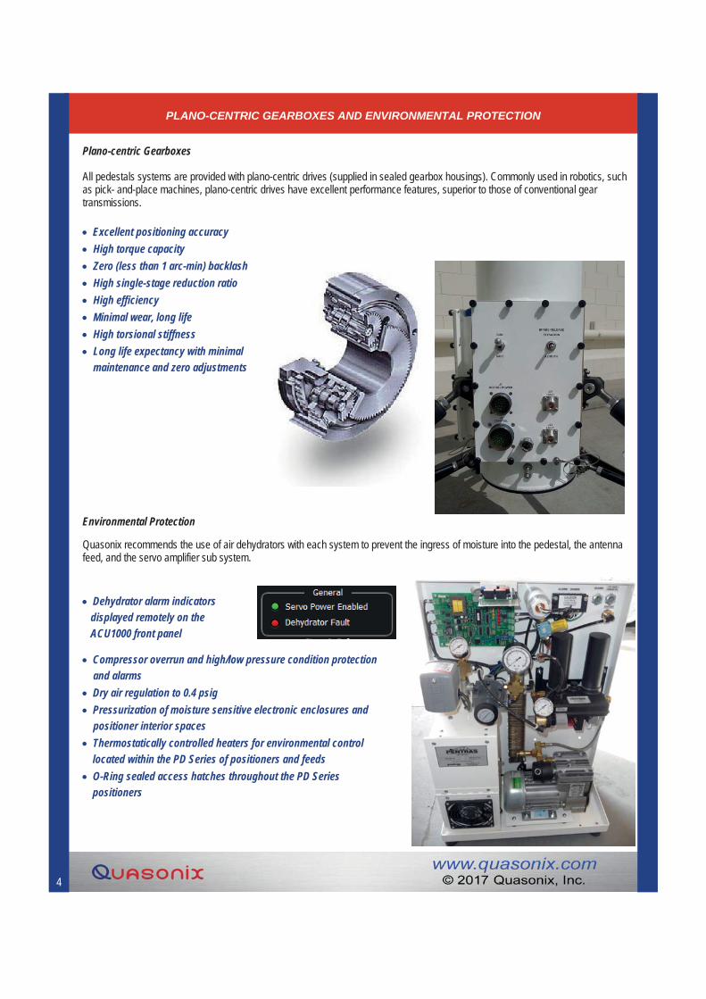
Excellent positioning accuracy High torque capacity Zero (less than 1 arc-min) backlash High single-stage reduction ratio High efficiency Minimal wear, long life High torsional stiffness Long life expectancy with minimal
maintenance and zero adjustments
4
PLANO-CENTRIC GEARBOXES AND ENVIRONMENTAL PROTECTION
Plano-centric Gearboxes
Environmental Protection
All pedestals systems are provided with plano-centric drives (supplied in sealed gearbox housings). Commonly used in robotics, such as pick- and-place machines, plano-centric drives have excellent performance features, superior to those of conventional gear transmissions.
Quasonix recommends the use of air dehydrators with each system to prevent the ingress of moisture into the pedestal, the antenna feed, and the servo amplifier sub system.
Dehydrator alarm indicators displayed remotely on the ACU1000 front panel
Compressor overrun and high/low pressure condition protection and alarms
Dry air regulation to 0.4 psig Pressurization of moisture sensitive electronic enclosures and
positioner interior spaces Thermostatically controlled heaters for environmental control
located within the PD Series of positioners and feeds O-Ring sealed access hatches throughout the PD Series
positioners

ANTENNA CONTROL UNIT (ACU)
5
ACU1000 Antenna Control Unit
Flexible Interfaces—Control Any Brand of Pedestal The Quasonix ACU1000 employs a modular design approach so it can control Quasonix antenna pedestals AND interface to legacy products from EMP, Malibu, and others
Intuitive User Interface Bright 15” touch screen with hand wheels or joystick for local control; Mouse and keyboard provide intuitive remote control; For remote-only applications, the ACU1000 is available without the touch screen chassis
Multiple Tracking Modes Accepts pointing data from remote customer slave sources; Server based local ACU allows for slaving of one PD series to another and enables tracking from user provided files of predicted or projected data
Robust Industrial Design Redundant power supplies and either Linux or Windows 7 operating systems yield rock-solid performance and zero maintenance
Client-Server Architecture for Maximum Operator Control Operates in either local or remote modes with the remote interface consuming only a few kbps of network bandwidth; Multiple operators can view the local ACU simultaneously while a request channel allows control to be moved to any remote
Supports HyperTrack™ Interface (2Q 2018) Bypassing the legacy AM and AGC interfaces entirely, the revolutionary HyperTrack™ interface from Quasonix brings you faster, more accurate tracking than you’ve ever seen before; Schedule a demo today
Comprehensive Diagnostics Built-in Test (BIT) and target simulation ensure peak performance on every mission; Comprehensive data logging utilities allow detailed post-mission analysis
ANTENNA CONTROL UNIT (ACU)
6
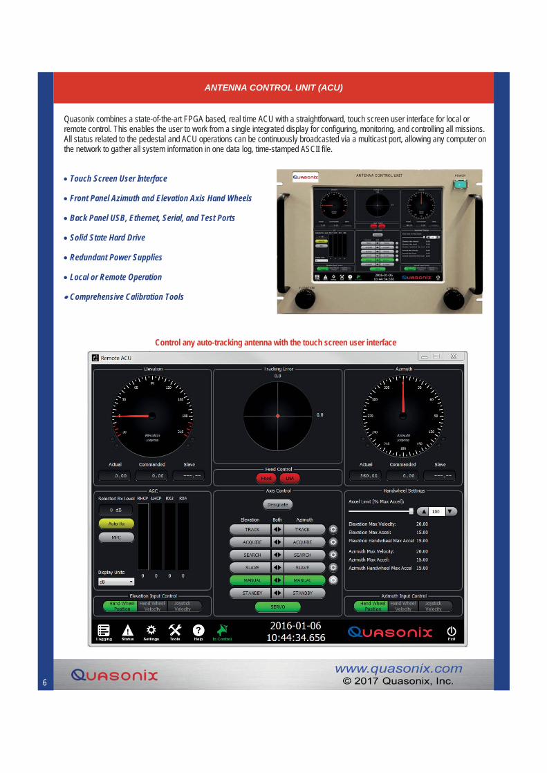
Quasonix combines a state-of-the-art FPGA based, real time ACU with a straightforward, touch screen user interface for local or remote control. This enables the user to work from a single integrated display for configuring, monitoring, and controlling all missions. All status related to the pedestal and ACU operations can be continuously broadcasted via a multicast port, allowing any computer on the network to gather all system information in one data log, time-stamped ASCII file.
Touch Screen User Interface
Front Panel Azimuth and Elevation Axis Hand Wheels
Back Panel USB, Ethernet, Serial, and Test Ports
Solid State Hard Drive
Redundant Power Supplies
Local or Remote Operation
Comprehensive Calibration Tools
Control any auto-tracking antenna with the touch screen user interface

ANTENNA TRACKING WITH HYPERTRACK™
HyperTrack™ 21st Century Antenna Tracking
7
NEW!
Revolutionary antenna tracking control loop Tightly integrates receiver with antenna control unit (ACU)
High Speed, all-digital interface between receivers and the ACU Very low and deterministic latency supports wider tracking loops Bi-directional information flow
Faster, more accurate tracking Especially important at C-band, where antenna beamwidth is smaller
Matched filter detection of scanning signal Dramatically improves rejection of AM induced by target motion
Typical Antenna System Optimized with HyperTrack™
Superior rejection of interfering signals ACU is not “fooled” by large signals that are not the signal being tracked
Tracking on intermittent downlink signals Optimized for time division duplex systems, such as iNET
Exclusive to Quasonix Legacy AM and AGC interfaces are still available on both the receiver and the ACU
Extensive diagnostic and simulation capabilities

MULTI-BAND ANTENNA FEEDS
Antenna Feeds
Over 120 Man-Years of Antenna Experience The Quasonix antenna team comprises design, manufacturing, and test experience dating back to the 1980s with several hundred systems delivered—many still in use 20 years or more after commissioning
Maintenance-Free Conical Scanning Utilizing brushless, hollow-shaft DC motors with permanently sealed bearings, high-precision balancing, and pressurized enclosures, Quasonix Conscan feeds provide decades of trouble free operation along with the highest achievable G/T for any size reflector
Electronic Scanning for Highly Dynamic Targets For applications where the target itself is creating a highly modulated signal (rotorcraft, for example), Quasonix offers electronic scanning with scan rates up to 50 kHz
Multiple Frequency Bands in a Single Feed Both the Conscan and Escan feeds are available in multi-band configurations covering Lower L, Upper L, S, and C bands in a single feed; Low loss, high selectivity cavity tuned filters for interference rejection
Dual Polarizations for Both Receive and Transmit Conscan and Escan feeds offer simultaneous left hand and right hand circular polarizations in all bands; The diversity combiner in your receiver merges those signals to improve link margin by up to 3 dB
Environmentally Sealed and Pressurized Pressurized environment for the feeds prevents moisture from entering the enclosure, further extending equipment life and ensuring consistent performance in any weather
Backward Compatible with Legacy Designs Use of standardized mounting rings and connections allows a high performance Quasonix feed to be a drop-in replacement for feeds from other manufacturers
Electronically Scanned Feeds
Electronic Scanning for Highly Dynamic Targets Quasonix Escan feeds sweep the beam by electronic means, allowing scan rates up to 50 kHz. These high scan rates can greatly mitigate the challenges inherent in tracking targets that impose high degrees of amplitude modulation on the transmitted signal (rotorcraft or spinning missiles, for example)
Precision Machining of Waveguides Assures best possible low VSWR and low axial ratio across the band
Acquisition Aid The Escan feed offers 10 dB to 12 dB of gain without a reflector making it ideal for use as an acquisition aid
8

MULTI-BAND ANTENNA FEEDS
Highest Possible G/T Quasonix Conscan feeds integrate hollow shaft brushless DC motors with the most innovative waveguides in the industry to cast the smallest shadow on the reflector. In conjunction with the direct routing of the waveguides to the RF output connectors, this ensures that the complete system is delivering the highest quality signal.
Optional Acquisition Aid For applications where the target may go out of view, Quasonix provides a range of low-gain tracking acquisition aid antennas. These RF assemblies can be mounted either behind the tracking feed assembly or at the side of the reflector. Providing low gain and large beamwidth, these acquisition aids are ideal for close in tracking and initial acquisition of targets. This is seamlessly integrated so that crossover between the two feeds requires no operator intervention.
Conscan Feed Acquisition Aid
Conical Scanning Feeds
9

PRECISION DRIVE TELEMETRY ANTENNA PART NUMBER BUILDERS
Quasonix Feeds Part Number Builder
Quasonix ACU Part Number Builder
10
C
ScanningC: Conscan Auto-TrackingE: Escan Auto-TrackingN: Non-Tracking
-QSX-AFD
Standard Prefix
Antenna Feed
- XXC
BandRefer to
band code table on page 11
Options, in any orderRefer to options table on page 11
- -
Feed Type
T
T: Conscan Auto-TrackingE: Escan Auto-TrackingN: Non-Tracking
VG
Options, in any order
QSX-ACU
Standard Prefix
Antenna Control
Unit
Servo Control Type
L
L: Local ACU Servo ControlE: Ethernet Remote Servo Ctrl (RMC)S: Single Mode Fiber Optic RMCM: Multi-Mode Fiber Optic RMC
Chassis
X
X: 8U Rack Mount, 15" Touchscreen Display, Azimuth/Elevation Hand Wheels
S: Small Form Factor, 3U Rack Mount, Blank Front Panel
Refer to options table on page 11
Quasonix Antenna System Part Number Builder
XXXXXQSX
Quasonix Product
Precision Drive
Antenna System
-
03 – 3 Feet04 – 4 Feet05 – 5 Feet06 – 6 Feet08 – 8 Feet10 – 10 Feet14 – 14 Feet16 – 16 Feet20 – 20 Feet
- X
P: Petals (Sectional)S: Solid
XX
Options, in any order
C: Conscan Auto-TrackingE: Escan Auto-TrackingN: Non-Tracking
-
Pedestal Size300450500750900
PD
Reflector Size
Solid/Sectional
- - X X
BandRefer to
band code table on page 11
XX
Refer to options on page 11
CW: Cable WrapS2: Slip Ring/2-Channel Rotary JointS3: Slip Ring/3-Channel Rotary Joint
Slip Ring/Cable Wrap
Feed Type

PRECISION DRIVE TELEMETRY ANTENNA SYSTEM OPTIONS
> AA Acquisition Aid > GY Gyroscope/IMU
> AS Auto Stow > GP Differential GPS
> CA Camera > PS Pedestal Spacer
> FC Fiber Optic Servo Control > SF Site-Specific Feed Filtering
> FR Fiber Optic RF > VG High/Low Gain Switch
Legend:
11
> AC Coaxial Acquisition Aid > TX Transmit Capable
> SF Site-Specific Filters > VG High/Low Gain Switch
ANTENNA FEED OPTIONS
ANTENNA ACU OPTIONS
> AS Auto Stow Control > TC IRIG-B Time Input
> GP Differential GPS Interface > TR TX/RX Switch Control
> GY Gyroscope/IMU Input > VG High/Low Gain Switch Control
> HT HyperTrack
BAND CODE TABLE

PRECISION DRIVE PEDESTALS
Side by Side Comparisons of Precision Drive Antenna Systems
PD300 PD450 PD500 PD750 PD900Antenna Capability
Up to 4 feet
(1.2M)
Up to 6 feet
(1.8M)
Up to 8 feet
(2.44M)
Up to 15 feet
(5M)
Up to 20 feet
(6.1M)
Typical Conscan Performance
4’ / 1.2 Meter
G/T - Beamwidth
6’ / 1.8 Meter
G/T - Beamwidth
8’ / 2.44 Meter
G/T - Beamwidth
16’ / 5 Meter
G/T - Beamwidth
20’ / 6.1 Meter
G/T - Beamwidth
1500 MHz -0.5 11.2° 3.5 7.5° 6.3 5.5° 12.7 2.7° 14.5 2.2°
2300 MHz 3.0 7.3° 7.0 4.9° 9.8 3.6° 16.2 1.7° 18.0 1.4°
Compliance(radians/ft lb) 1.75 x 10⁻⁵ 2.3 x 10⁻⁵ 2.0 x 10⁻⁵ 4.0 x 10⁻⁷ 2.0 x 10⁻⁷
Pedestal Wgt 175 lbs 400 lbs 800 lbs 2400 lbs 3950 lbs
Wind Operating Gusting Survival
50 MPH 65 MPH 120 MPH
50 MPH 65 MPH 120 MPH
50 MPH 65 MPH 120 MPH
50 MPH 65 MPH 120 MPH
50 MPH 65 MPH 120 MPH
Power Requirements
1.5 KW 115/230 VAC 50-60 Hz, 1Ø
2.5 KW 115/230 VAC 50-60 Hz, 1Ø
3.0 KW 115/230 VAC 50-60 Hz, 1Ø
4.0 KW 208/400 VAC 50-60 Hz, 3Ø
5.0 KW 208/400 VAC 50-60 Hz, 3Ø
Torque Cont-125 ft-lbs Peak-250 ft-lbs
Cont-235 ft-lbs Peak-400 ft-lbs
Cont-900 ft-lbs Peak-1800 ft-lbs
Cont-3600 ft-lbs Peak-7200 ft-lbs
Cont-5800 ft-lbs Peak-12000 ft-lbs
Velocity 30°/sec 30°/sec 30°/sec 20°/sec 20°/sec
Acceleration 40°/sec2 40°/sec2 40°/sec2 20°/sec2 20°/sec2
Environmental Operating Temperature -30°C to +52°CStorage Temperature -54°C to +71°CRelative Humidity Up to 100%, including condensation
Rain Up to 4 inches per hour
Ice 1/2 inch, Radial
Backlash 0.016 degrees typical
VSWR 2:0:1 maximum
Axial Ratio 2.0 dB maximum Polarization Simultaneous dual or single, all variants of Circular or Linear polarization
Travel Azimuth: Continuous, Optional up to + 420° with pre-limits Elevation: -8° to +188° (Software), -10° to +190° (Electrical), -12° to +192° (Mechanical)
12

13
CUSTOM PORTABLE ENCLOSURES

Reinventing Telemetry™ Reinventing Telemetry™
QTrack™ PORTABLE LOW GAIN ANTENNA
Simplified Two Cable Connection Requires only 115 VAC 1Ø 60 power at less than 13 Amps and an RJ45 Ethernet connection (with IP option)
L, S, and C-band Operation Simultaneous LHCP and RHCP RF outputs
Dual Axis Pedestal Tri-band SCM feed mounted in a yoke based, elevation over azimuth dual axis pedestal; includes power supplies, slip rings, and rotary joint
Electronic Scanning for Highly Dynamic Targets Quasonix feeds sweep the beam electronically allowing scan rates up to 50 kHz—greatly mitigating the challenges inherent in tracking targets that impose high degrees of amplitude modulation on transmitted signal
Antenna Control Unit (ACU) Real time pedestal interface; Bright 15” touch screen with handwheels or USB joystick for local control; Mouse and keyboard provide intuitive remote control; For remote-only applications, the ACU1000 is available without the touch screen chassis
ACU Client-Server Architecture for Maximum Operator Control Operates in either local or remote modes with the remote interface consuming only a few kbps of network bandwidth
Self-Contained Ground Station The low gain antenna based on the Quasonix Acquisition Aid Antenna, coupled with the industry-leading RDMS telemetry receiver, is the perfect solution for pole or mast mounted antenna applications
Portable Carrying case doubles as a local mount for a free-standing antenna; incorporates built-in leveling feet (3) and level indicator
Portable Antenna Solution Complete ground station, from RF electromagnetic waves as input to clock and data (or optional IP packets) at the output Dual-axis auto-tracking platform Transport case may be used as a local mount

ANTENNA AND PEDESTAL SPECIFICATIONS
Antenna Specifications Operating Frequency 1435.0 - 2400.0 MHz continuous, 4400.0—5250.0 MHz continuous Polarization Simultaneous Right Hand and Left Hand Circular VSWR 2:0:1 maximum Axial Ratio 2.0 dB maximum Antenna Type Electronic Scanning Array Size (Diameter) 13.25 inches nominal Weight < 15 lbs (7 kg)
Antenna Gain (nominal, linear polarized receive, RHCP and LHCP outputs combined)
1435.0 MHz +7.0 dB 2400.0 MHz +10.0 dB 4400.0 MHz +9.0 dB 5250.0 MHz +9.0 dB
Antenna Beamwidth (3 dB) (nominal) 40° Sidelobes (nominal) 10 dBp Environmental
Temperature Operating -40°C to +52°C Storage -54°C to +71°C
Relative Humidity Up to 100%, including condensation (radome protected)
Environmental Operating Temperature -40°C to +52°C Storage Temperature -54°C to +71°C Relative Humidity Up to 100%, including condensation (radome protected) Rain Up to 4 inches per hour Ice 1/2 inch, Radial Wind Operating 50 MPH (80 Km/Hr), Gusting to 65 MPH (190Km/Hr), Survival at 120 MPH (193 Km/Hr)
Type Elevation/Azimuth Backlash < 0.2 degrees Velocity > 30°/sec Acceleration > 40°/sec2 Travel Azimuth Continuous Elevation -90° to +90° (Software, Electrical, and Mechanical limited provided) RF Cabling Capability Two RF channels supporting frequencies through C-band, VSWR 2.0:1 Maximum each RF channel Weight 25 lbs nominal Power Requirements Less than 13 A @115 VAC, 60 Hz, 1Ø
Pedestal Specifications
15
Quasonix Antenna System Part
Number Builder
X -QSX-QT
Quasonix Product
QTrack Antenna System
- XXXXX
Band
Control Cable Length (ft)
Refer to Band Code Table on page 11 -TP: Tripod
-EE: Rugged System Enclosure
Options, in any order

Reinventing Telemetry™ Reinventing Telemetry™
Photo Courtesy of SPACEX
Ivan Cholakov/Shutterstock.com
Galactic Headquarters 6025 Schumacher Park Drive West Chester, OH 45069 (513) [email protected]
Antenna Division 353 Science Drive Moorpark, CA 93021 (805) [email protected]
Instrumentation Devices Srl Via Acquanera 29 - 22100 COMO (Italy) ph +39 031 525 391- fax +39 031 507 984 [email protected] - www.instrumentation.it
Questi prodotti sono distribuiti e supportati in Italia da: