Precision Control of Antenna Positioner Using P … · Precision Control of Antenna Positioner...
12
ISBN: 97-8-93-81195-82-6 Proceedings of NJCIET2015 Canara Engineering College, Mangalore NJCIET-2015 486 Precision Control of Antenna Positioner Using P and PI Controllers Sharon Shobitha.O 1 K.L.Ratnakar 2 G.Sivasankaran 3 1 2 nd Year M. Tech CAID, Sri Siddhartha Institute of Technology, Tumkur -572105, Karnataka, India E-mail: sharon06shobitha1991@gmail.com 2 Professor, Dept of EEE, Sri Siddhartha Institute of Technology, Tumkur -572105, Karnataka, India E-mail: kl_ratnakar@rediffmail.com 3 Consultant in SYSTEM CONTROLS and retired program director for UAV, DRDO, Bangalore -560016, Karnataka, India E-mail: sivasankaran@systemcontrols.com ABSTRACT: Antenna positioners usually used for dynamic tracking and telemetry data purpose, such as data from missiles or aircraft. Hence control system design using servo BLDC motor a PID controller and a gear box for loop stabilization and jitter isolation requirement for both azimuth and elevation has been carried out. And their respective frequency response and time response will be used for the design purpose. Certain non-linearity such as rate disturbance for different frequencies are superimposed in the model to verify the design and evaluate the performance using MATLAB software. Keywords: antenna positioner, BLDC motor, PID controller. 1. Introduction: Antennas are designed to transmit and receive radio waves which are used to track static and dynamic systems like ships, airplanes and guided missiles and also for civil applications as well.Antenna positioning is the interface that positions or steers the antenna in azimuth and elevation planes of operation, in order to provide high reliability while withstanding severe environmental conditions. Positioning systems have been traditionally implemented using DC motors due to the relative ease in controlling them. However, there are still disadvantages in using such motors for positioning systems i.e in particular, for high speed repetitive motion, the brushes are subject to excessive mechanical wear and consequently lead to a decrease in performance. Positioning systems were then implemented using stepper motors but as the rotor follows the command position, if pulse frequency higher than natural frequency of the motor then the rotor will lose synchronization, and the user has no way to be sure that the motor has actually reached the desired position. For the reasons just enumerated positioning systems are now being implemented using servo motors, the main reason to use servo systems is to improve transient response times, steady state errors, to meet the torque and speed requirements and are suitable to run in any environment. PID controller is unquestionably the most commonly used control algorithm. The main reason is its relatively simple structure, which can be easily understood and implemented in practise. As the antenna’s are placed in the open area there will be disturbances occurred such as jitter isolation disturbance, wind load effect, stiffness etc. in this project only the jitter isolation has been carried out. Further we are going to see the proposed system i.e BLDC motor model in section 2, experimental details in section 3. Section 4 contains the conduction procedurethat is the current, velocity and position loop models and the model with disturbance are included , section 5 contains the simulation results obtained for the three loops and the disturbances using software tool called MATLAB. Section 6 contains the conclusion and finally the references.
Transcript of Precision Control of Antenna Positioner Using P … · Precision Control of Antenna Positioner...
ISBN: 97-8-93-81195-82-6 Proceedings of NJCIET2015
Canara Engineering College, Mangalore NJCIET-2015 486
Precision Control of Antenna Positioner Using P and PI Controllers
Sharon Shobitha.O1
K.L.Ratnakar2
G.Sivasankaran3
12nd Year M. Tech CAID, Sri Siddhartha Institute of Technology, Tumkur -572105, Karnataka, India
E-mail: [email protected]
2Professor, Dept of EEE, Sri Siddhartha Institute of Technology, Tumkur -572105, Karnataka, India
E-mail: [email protected]
3Consultant in SYSTEM CONTROLS and retired program director for UAV, DRDO, Bangalore -560016, Karnataka, India
E-mail: [email protected]
ABSTRACT: Antenna positioners usually used for dynamic tracking and telemetry data purpose, such as data from missiles or
aircraft. Hence control system design using servo BLDC motor a PID controller and a gear box for loop stabilization and jitter
isolation requirement for both azimuth and elevation has been carried out. And their respective frequency response and time
response will be used for the design purpose. Certain non-linearity such as rate disturbance for different frequencies are
superimposed in the model to verify the design and evaluate the performance using MATLAB software.
Keywords: antenna positioner, BLDC motor, PID controller.
1. Introduction:
Antennas are designed to transmit and receive radio waves which are used to track static and dynamic systems like
ships, airplanes and guided missiles and also for civil applications as well.Antenna positioning is the interface that
positions or steers the antenna in azimuth and elevation planes of operation, in order to provide high reliability while
withstanding severe environmental conditions. Positioning systems have been traditionally implemented using DC
motors due to the relative ease in controlling them. However, there are still disadvantages in using such motors for
positioning systems i.e in particular, for high speed repetitive motion, the brushes are subject to excessive
mechanical wear and consequently lead to a decrease in performance. Positioning systems were then implemented
using stepper motors but as the rotor follows the command position, if pulse frequency higher than natural frequency
of the motor then the rotor will lose synchronization, and the user has no way to be sure that the motor has actually
reached the desired position. For the reasons just enumerated positioning systems are now being implemented using
servo motors, the main reason to use servo systems is to improve transient response times, steady state errors, to
meet the torque and speed requirements and are suitable to run in any environment.
PID controller is unquestionably the most commonly used control algorithm. The main reason is its relatively simple
structure, which can be easily understood and implemented in practise. As the antenna’s are placed in the open area
there will be disturbances occurred such as jitter isolation disturbance, wind load effect, stiffness etc. in this project
only the jitter isolation has been carried out.
Further we are going to see the proposed system i.e BLDC motor model in section 2, experimental details in section
3. Section 4 contains the conduction procedurethat is the current, velocity and position loop models and the model
with disturbance are included , section 5 contains the simulation results obtained for the three loops and the
disturbances using software tool called MATLAB. Section 6 contains the conclusion and finally the references.
ISBN: 97-8-93-81195-82-6 Proceedings of NJCIET2015
Canara Engineering College, Mangalore NJCIET-2015 487
+ +
= −
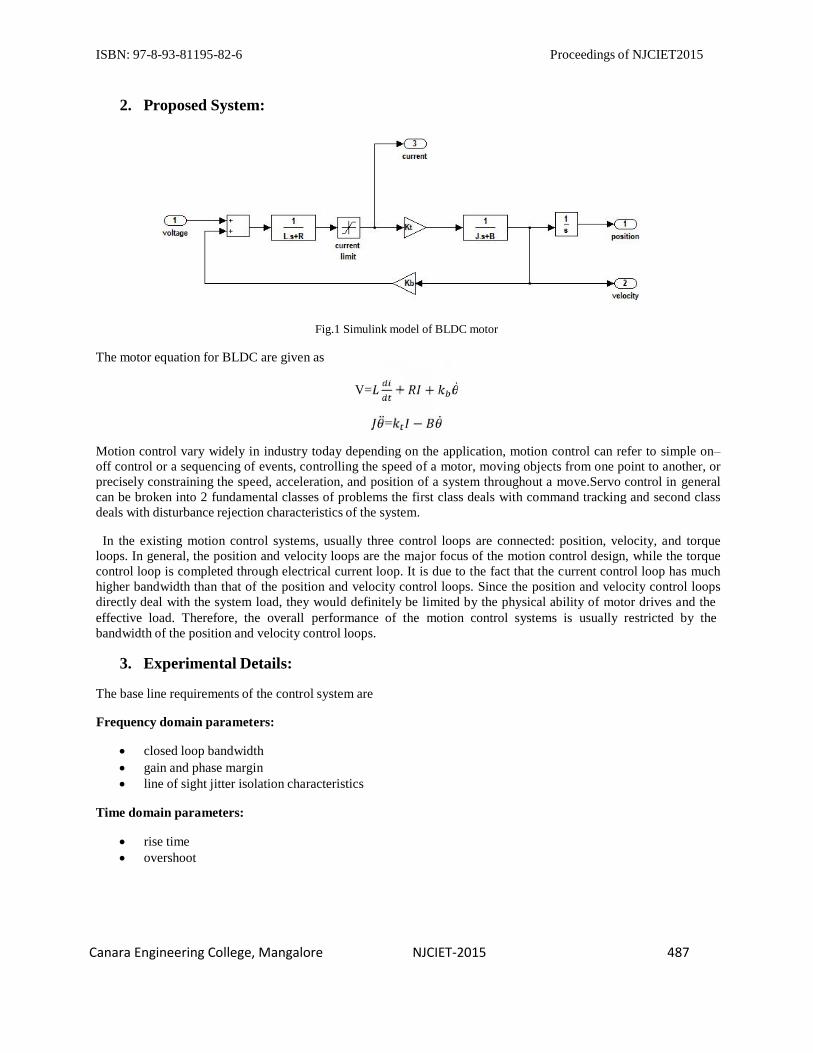
2. Proposed System:
Fig.1 Simulink model of BLDC motor
The motor equation for BLDC are given as
V=
Motion control vary widely in industry today depending on the application, motion control can refer to simple on–
off control or a sequencing of events, controlling the speed of a motor, moving objects from one point to another, or
precisely constraining the speed, acceleration, and position of a system throughout a move.Servo control in general
can be broken into 2 fundamental classes of problems the first class deals with command tracking and second class
deals with disturbance rejection characteristics of the system.
In the existing motion control systems, usually three control loops are connected: position, velocity, and torque
loops. In general, the position and velocity loops are the major focus of the motion control design, while the torque
control loop is completed through electrical current loop. It is due to the fact that the current control loop has much
higher bandwidth than that of the position and velocity control loops. Since the position and velocity control loops
directly deal with the system load, they would definitely be limited by the physical ability of motor drives and the
effective load. Therefore, the overall performance of the motion control systems is usually restricted by the
bandwidth of the position and velocity control loops.
3. Experimental Details:
The base line requirements of the control system are
Frequency domain parameters:
closed loop bandwidth
gain and phase margin
line of sight jitter isolation characteristics
Time domain parameters:
rise time
overshoot

ISBN: 97-8-93-81195-82-6 Proceedings of NJCIET2015
Canara Engineering College, Mangalore NJCIET-2015 488
Mechanical parameter estimation:
parameters Azimuth elevation Inertia torque 1.82Nm 1.65Nm
Friction torque 3.0Nm 3.0Nm Wind torque 30.93Nm 16.71Nm
Holding torque - 55.13 Safety factor 1.2 1.2
Table1:mechanical parameters
Considering the above mentioned requirements the suitable motors are selected i.e for Azimuth 28LT12
portescapmotor is selected and for Elevation RE35 maxon motor is selected.
Motor details:
ELEVATION:
Supply voltage(V) 24V Inductance (L) 0.191mH Resistance (R) 0.583Ω
Torque constant (Kt) 29.2mNm/A Motor inertia (Jm) 79.2kgm
2 Load inertia( Jl) 3.1kgm
2 Back EMF constant (Kb) 29.12mV/rad/sec
Current (I) 3.62A Gear ratio 21*50
AZIMUTH:
Table 2: servomotor details for elevation
Supply voltage(V) 18V
Inductance (L) 0.5mH Resistance (R) 6.2Ω
Torque constant (Kt) 21.4mNm/A Motor inertia (Jm) 10.7kgm
2 Load inertia(Jl) 3.35kgm
2 Back EMF constant (Kb) 21.4mV/rad/sec
Current (I) 3A Gear ratio 24*50
4. Conduction Procedure:
Table 3: servomotor details for azimuth
Fig2. Current, velocity and position loop controller model

ISBN: 97-8-93-81195-82-6 Proceedings of NJCIET2015
Canara Engineering College, Mangalore NJCIET-2015 489
The design of current, velocity and position loop controller is as shown in fig 2. Where the targeted bandwidth for
current loop is 1KHz, for velocity loop 35Hz and for position loop 7Hz, the gain at that particular frequencies are
observed. The observed gain is then augmented with the unity feedback gain to achieve the adequate current,
velocity and position loop bandwidth and their respective frequency responses are plotted (bode plot) . Time
responses are plotted (step response)for a step input of 1° and their respective rise time, overshoot and max. speed
are noted.
Fig 3. Velocity closed loop with rate disturbance and no input command
Similarly now adding the disturbance, the jitter isolation characteristics of the servo loop are studied by considering
a positon disturbance of 3mrad which is equivalent to injecting a rate disturbance of 0.0189 rad/sec amplitude in the
velocity loop at different frequencies (1Hz -3Hz) and monitoring the position output. The output jitter amplitude is
required to be within 300micro radians. The model of velocity closed loop with rate disturbance and no input
command is as shown in fig 3. And thus the results are obtained.
5. Simulation Results
The computer simulation has been done using MATLAB/Simulink which is a software tool developed by Math
works.
AZIMUTH: frequency response
Fig4.1current loop (open)

ISBN: 97-8-93-81195-82-6 Proceedings of NJCIET2015
Canara Engineering College, Mangalore NJCIET-2015 490
Fig4.2 current loop (closed)
Fig4.3 velocity loop (open)
Fig4.4 velocity loop (closed)

ISBN: 97-8-93-81195-82-6 Proceedings of NJCIET2015
Canara Engineering College, Mangalore NJCIET-2015 491
Fig4.5 position loop (open)
Fig4.6 position loop (closed)
Control loop Open loop B.W Closed loop B.W
at 3db Current(1KHz) -12.5db; K=4.21 1KHz Velocity(35Hz) -4.75db; K=1.72 32.8Hz Position(7Hz) -33.4db; K=47 8.76Hz
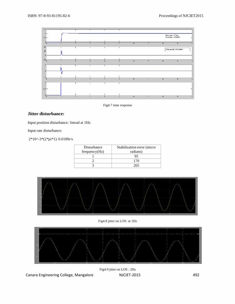
Time response:
Rise time: 47.7ms
Overshoot: 3.4660%
Max Speed: 0.39r/s
ISBN: 97-8-93-81195-82-6 Proceedings of NJCIET2015
Canara Engineering College, Mangalore NJCIET-2015 492
Jitter disturbance:
Input position disturbance: 3mrad at 1Hz
Fig4.7 time response
Input rate disturbance:
2*10^-3*(2*pi*1): 0.0189r/s
Disturbance frequency(Hz)
Stabilization error (micro radians)
1 95 2 170 3 265
Fig4.8 jitter on LOS: at 1Hz
Fig4.9 jitter on LOS : 2Hz

ISBN: 97-8-93-81195-82-6 Proceedings of NJCIET2015
Canara Engineering College, Mangalore NJCIET-2015 493
ELEVATION:
Fig4.10 jitter on LOS: 3Hz
Fig4.11 current loop (open)
Fig4.12 current loop (closed)
Fig4.13 velocity loop (open)

ISBN: 97-8-93-81195-82-6 Proceedings of NJCIET2015
Canara Engineering College, Mangalore NJCIET-2015 494
Fig4.14 velocity loop (closed)
Fig4.15 position loop (open)
Fig4.16 position loop (closed)
Control loop Open loop B.W Closed loop B.Wat 3db
Current(1KHz) 1.3db; K=1.16 1KHz Velocity(35Hz) -10.2db; K=3.2 30.1Hz Position(7Hz) -34.2db; K=51.28 8.44Hz
ISBN: 97-8-93-81195-82-6 Proceedings of NJCIET2015
Canara Engineering College, Mangalore NJCIET-2015 495
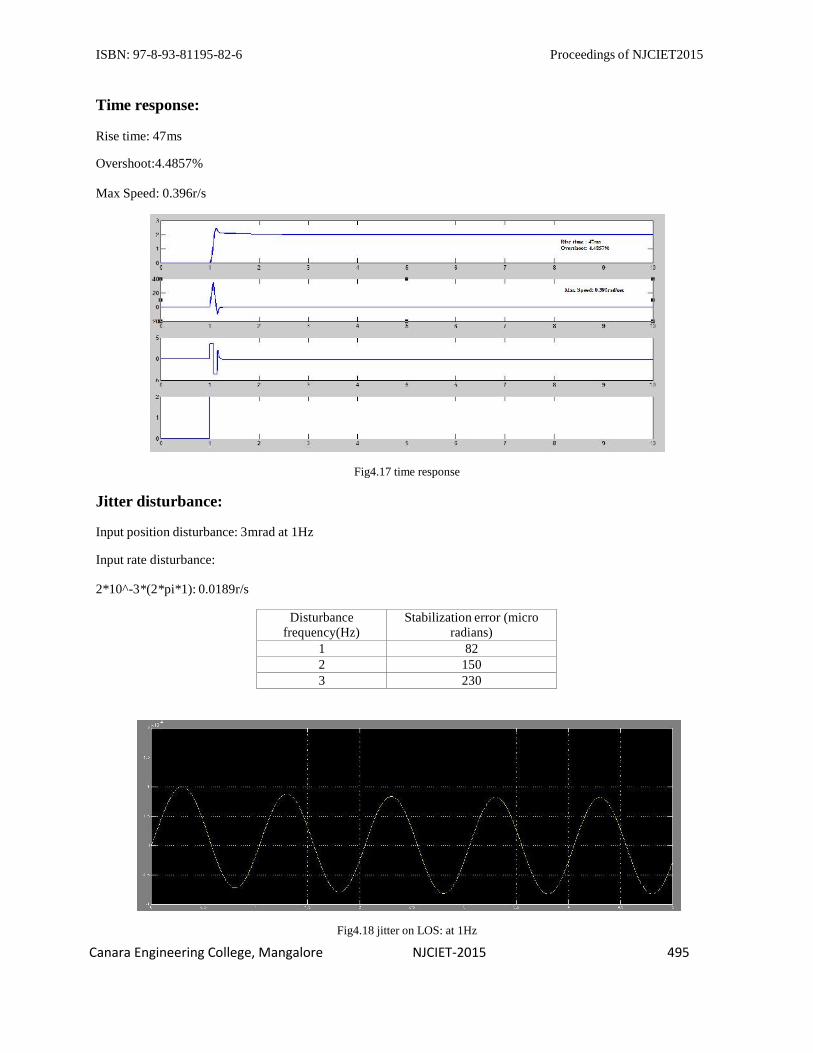
Time response:
Rise time: 47ms
Overshoot:4.4857%
Max Speed: 0.396r/s
Jitter disturbance:
Input position disturbance: 3mrad at 1Hz
Fig4.17 time response
Input rate disturbance:
2*10^-3*(2*pi*1): 0.0189r/s
Disturbance frequency(Hz)
Stabilization error (micro radians)
1 82 2 150 3 230
Fig4.18 jitter on LOS: at 1Hz

ISBN: 97-8-93-81195-82-6 Proceedings of NJCIET2015
Canara Engineering College, Mangalore NJCIET-2015 496
Fig4.19 jitter on LOS: at 2Hz
Fig4.2 jitter on LOS: at 3Hz
6. Conclusion:
Advancements in modern computing technologies have shifted the control of RF measurement positioners into the
digital domain with increased system flexibility. These advancements provide the opportunity to improve
measurement capabilities and accuracies through the use of advanced secondary feedback devices with true error
compensation control loops.
The control system design of antenna positioners for loop stabilization and jitter isolation requirement for both
azimuth and elevation channels has been carried out using two BLDC motors and PI controller along with a
planetary gear to meet the torque requirements. The frequency response for the three control loops and the time
response are plotted as per the required specifications and the jitter isolation characteristics, considering a position
disturbance injected in the velocity loop for different frequencies has been done and their respective position outputs
has been monitored. All the results presented above, using mathematical equations and simulation in MATLAB.
References:
1. Mohammed Ahmed, 2Samsul Bahari B Mohd Noor, 3Mohd Khair B Hassan, 4Azura BtCheSoh ,A Review
of Strategies for Parabolic Antenna Control, may 2014.
2. Nay lintun, liuqiang, Modeling and Control of DC Motor Driving in XY Table,

ISBN: 97-8-93-81195-82-6 Proceedings of NJCIET2015
Canara Engineering College, Mangalore NJCIET-2015 497
3. 1Shreeji S. Sheth, 2Sima K GonsaiAntenna Position Control Systems, Review and New Perception, oct
2013
4. Aimeng Wang , China Li Zhang ; Liang Wei ; The design and implementation of the digital servo system for the satellite antenna Dept. of Electr. Eng., North China Electr. Power Univ., Baoding
5. .Javier R. Movellan, DC motors .july 2010
6. M.Zribi and J. Chaisson, Position Control of a PM Stepper Motor by Exact Linearization. IEEE
transactions on automatic control. Vol.36, no.5
7. Mehmet akar, ismailtemiz, motion controller design for the speed control of DC sevomotor, 2007
8. Parker,Fundamentals of motion control.
9. Myeongkyun Kim, Jinsoo Kim and Oh Yang,Precise Attitude Control System Design for the Tracking of
Parabolic Satellite Antenna.,2013.
10. Chang-hocho, sang-hyo lee, tae-yong kwon, cheol lee, antenna control system using teacking algorithm
with H infinity controller,2003.