Pre-disassembly Instructionstabletparts.ru/wp-content/uploads/2016/08/S1002.pdf · 3-6...
54
3-6 Pre-disassembly Instructions 0 Before proceeding with the disassembly procedure, make sure to do the following: 1. Turn off the power to the system and all peripherals. 2. Unplug the AC adapter and all power and signal cables from the system. Figure 3-1. AC Adapter 3. Place the system on a flat, stable surface.
Transcript of Pre-disassembly Instructionstabletparts.ru/wp-content/uploads/2016/08/S1002.pdf · 3-6...

3-6
Pre-disassembly Instructions 0
Before proceeding with the disassembly procedure, make sure to do the following:
1. Turn off the power to the system and all peripherals.
2. Unplug the AC adapter and all power and signal cables from the system.
Figure 3-1. AC Adapter
3. Place the system on a flat, stable surface.
3-7
Disassembly Process 0
The disassembly process is divided into the following sections:
Main unit disassembly
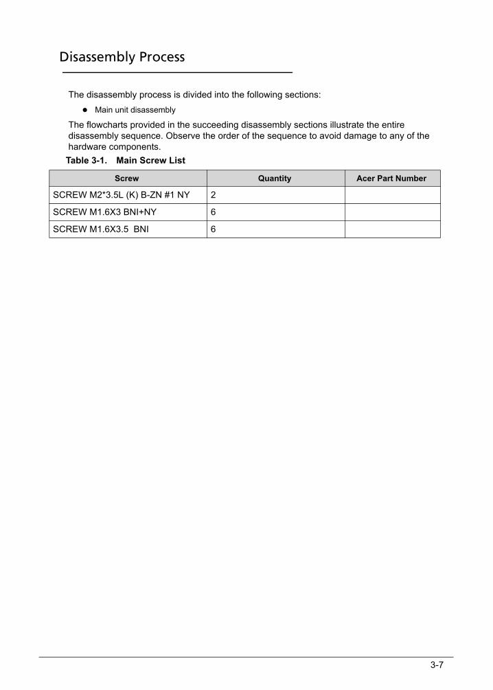
The flowcharts provided in the succeeding disassembly sections illustrate the entire disassembly sequence. Observe the order of the sequence to avoid damage to any of the hardware components.
Table 3-1. Main Screw List
Screw Quantity Acer Part Number
SCREW M2*3.5L (K) B-ZN #1 NY 2
SCREW M1.6X3 BNI+NY 6
SCREW M1.6X3.5 BNI 6
3-8
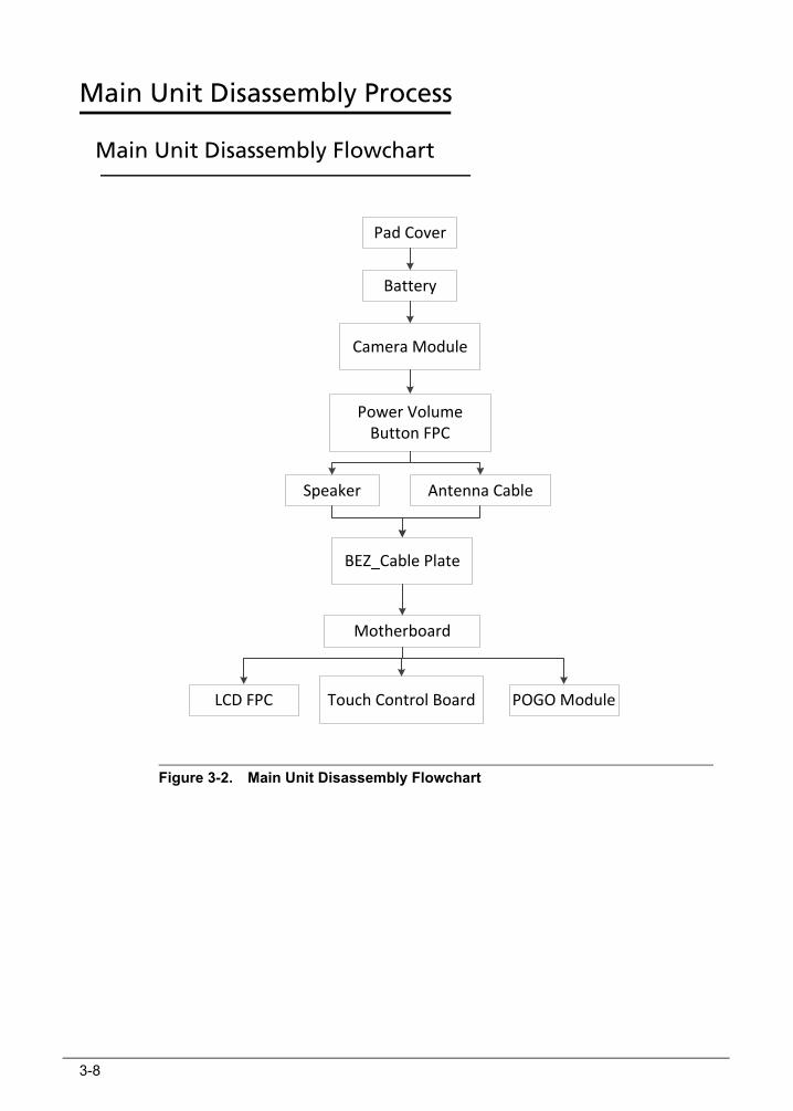
Main Unit Disassembly Process 0
Main Unit Disassembly Flowchart 0
Figure 3-2. Main Unit Disassembly Flowchart
Pad Cover
Battery
BEZ_Cable Plate
Speaker
Motherboard
Camera Module
Power Volume Button FPC
Antenna Cable
LCD FPC POGO ModuleTouch Control Board
3-9
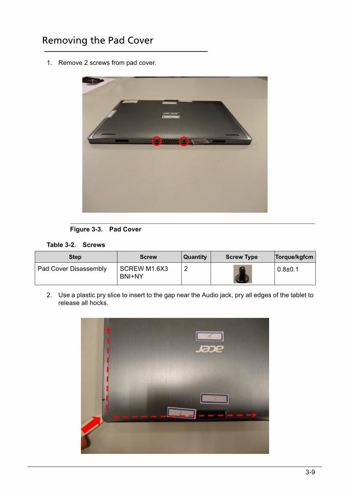
Removing the Pad Cover 0
1. Remove 2 screws from pad cover.
Figure 3-3. Pad Cover
Table 3-2. Screws
2. Use a plastic pry slice to insert to the gap near the Audio jack, pry all edges of the tablet to release all hocks.
Step Screw Quantity Screw Type Torque/kgfcm
Pad Cover Disassembly SCREW M1.6X3 BNI+NY
2 0.8±0.1
3-10
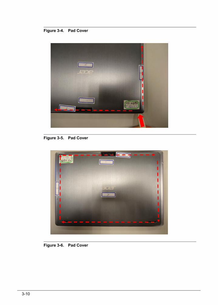
Figure 3-4. Pad Cover
Figure 3-5. Pad Cover
Figure 3-6. Pad Cover

3-11
3. Lift the upper edge of pad cover to remove it from main part.
Figure 3-7. Pad Cover

3-12
Removing the Battery 0
1. Disconnect the battery cable from main board.
Figure 3-8. Battery
2. Lift to remove the battery from LCD panel.
Figure 3-9. Battery
3-13
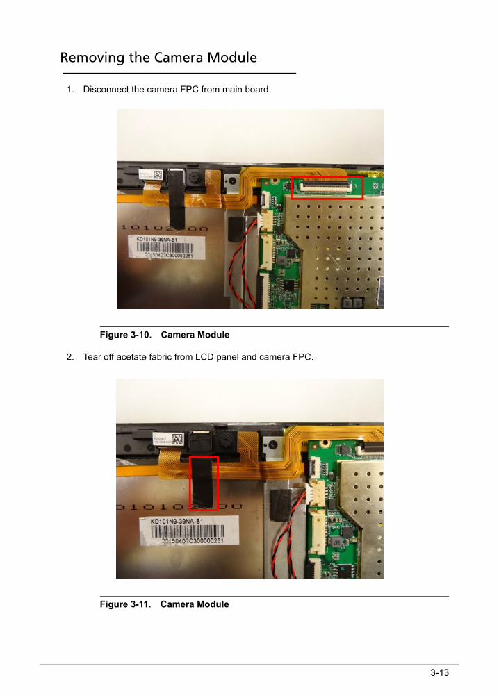
Removing the Camera Module 0
1. Disconnect the camera FPC from main board.
Figure 3-10. Camera Module
2. Tear off acetate fabric from LCD panel and camera FPC.
Figure 3-11. Camera Module
3-14
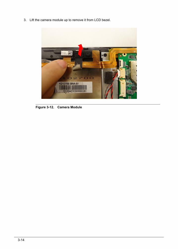
3. Lift the camera module up to remove it from LCD bezel.
Figure 3-12. Camera Module
3-15
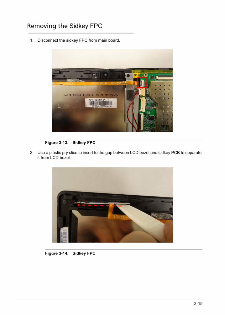
Removing the Sidkey FPC 0
1. Disconnect the sidkey FPC from main board.
Figure 3-13. Sidkey FPC
2. Use a plastic pry slice to insert to the gap between LCD bezel and sidkey PCB to separate it from LCD bezel.
Figure 3-14. Sidkey FPC
3-16
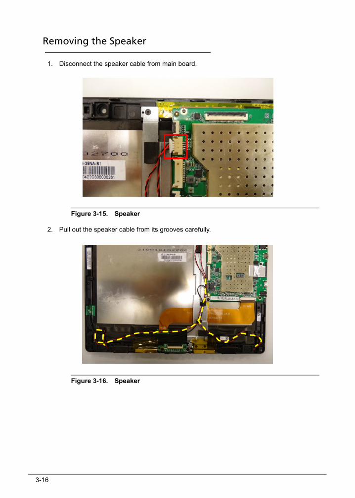
Removing the Speaker 0
1. Disconnect the speaker cable from main board.
Figure 3-15. Speaker
2. Pull out the speaker cable from its grooves carefully.
Figure 3-16. Speaker

3-17
3. Use a pair of tweezers to remove the speaker boxes from LCD bezel.
Figure 3-17. Speaker
Figure 3-18. Speaker
3-18
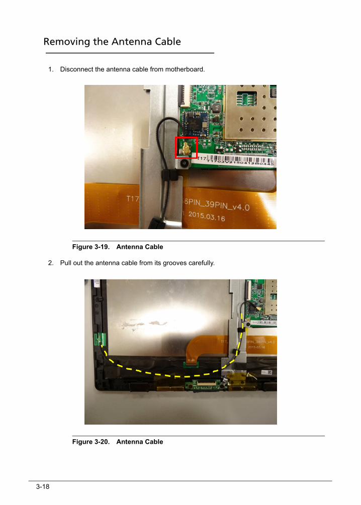
Removing the Antenna Cable 0
1. Disconnect the antenna cable from motherboard.
Figure 3-19. Antenna Cable
2. Pull out the antenna cable from its grooves carefully.
Figure 3-20. Antenna Cable
3-19
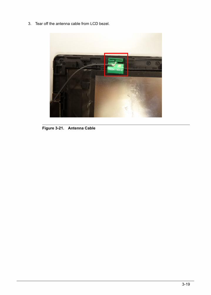
3. Tear off the antenna cable from LCD bezel.
Figure 3-21. Antenna Cable

3-20
Removing the PAD Plate 0
1. Tear off the tape from magnet.
Figure 3-22. PAD Plate
2. Remove 4 screws from PAD plate.
Figure 3-23. PAD Plate
3-21
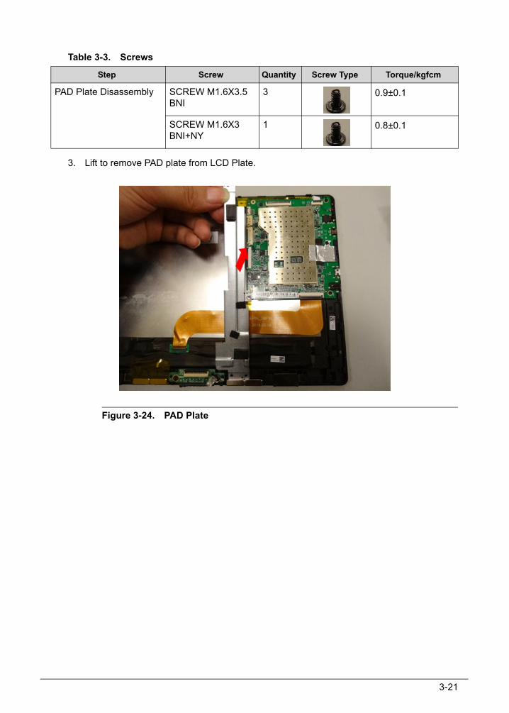
Table 3-3. Screws
3. Lift to remove PAD plate from LCD Plate.
Figure 3-24. PAD Plate
Step Screw Quantity Screw Type Torque/kgfcm
PAD Plate Disassembly SCREW M1.6X3.5 BNI
3 0.9±0.1
SCREW M1.6X3 BNI+NY
1 0.8±0.1
3-22
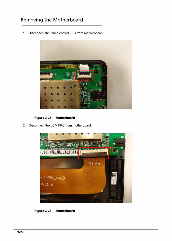
Removing the Motherboard 0
1. Disconnect the touch control FFC from motherboard.
Figure 3-25. Motherboard
2. Disconnect the LCM FPC from motherboard.
Figure 3-26. Motherboard
3-23
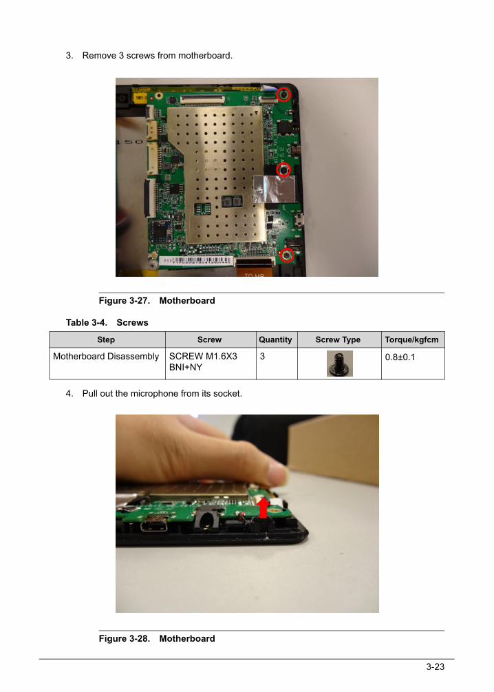
3. Remove 3 screws from motherboard.
Figure 3-27. Motherboard
Table 3-4. Screws
4. Pull out the microphone from its socket.
Figure 3-28. Motherboard
Step Screw Quantity Screw Type Torque/kgfcm
Motherboard Disassembly SCREW M1.6X3 BNI+NY
3 0.8±0.1

3-24
5. Lift to remove the motherboard.
Figure 3-29. Motherboard
3-25
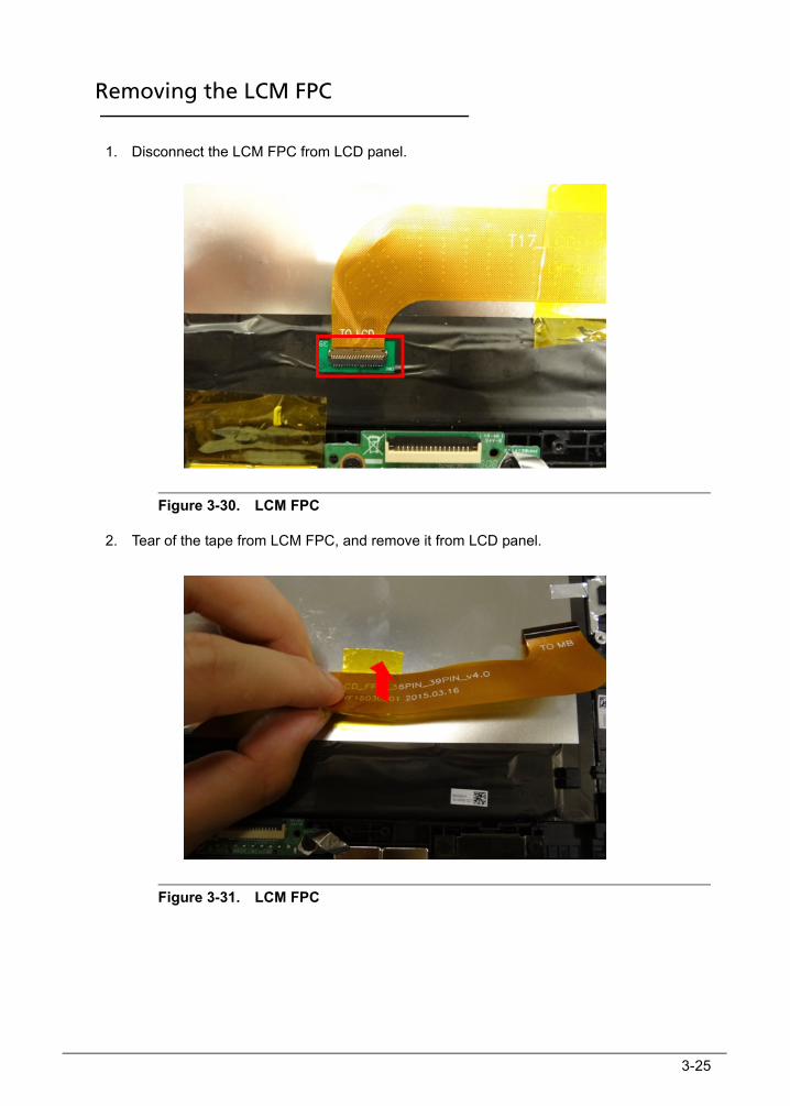
Removing the LCM FPC 0
1. Disconnect the LCM FPC from LCD panel.
Figure 3-30. LCM FPC
2. Tear of the tape from LCM FPC, and remove it from LCD panel.
Figure 3-31. LCM FPC
3-26
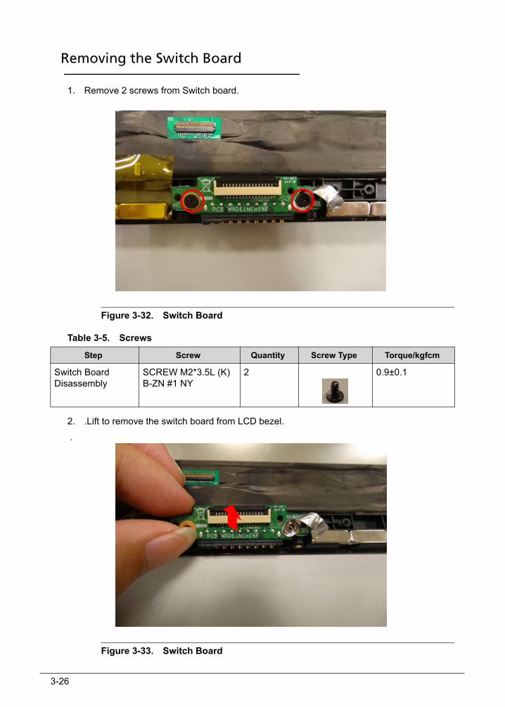
Removing the Switch Board 0
1. Remove 2 screws from Switch board.
Figure 3-32. Switch Board
Table 3-5. Screws
2. .Lift to remove the switch board from LCD bezel.
.
Figure 3-33. Switch Board
Step Screw Quantity Screw Type Torque/kgfcm
Switch Board Disassembly
SCREW M2*3.5L (K) B-ZN #1 NY
2 0.9±0.1
3-27
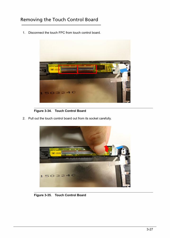
Removing the Touch Control Board 0
1. Disconnect the touch FPC from touch control board.
Figure 3-34. Touch Control Board
2. Pull out the touch control board out from its socket carefully.
Figure 3-35. Touch Control Board
3-28
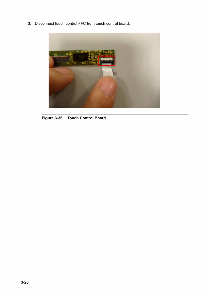
3. Disconnect touch control FFC from touch control board.
Figure 3-36. Touch Control Board
3-29
Main Unit Reassembly Procedure 0
Replacing the Touch Control Board 0
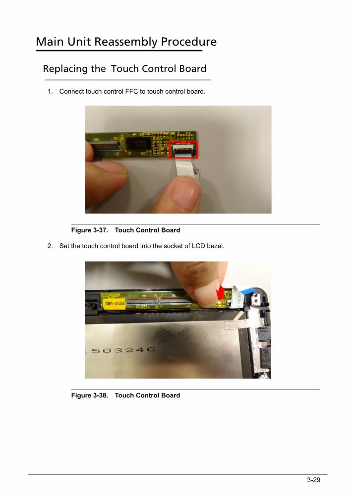
1. Connect touch control FFC to touch control board.
Figure 3-37. Touch Control Board
2. Set the touch control board into the socket of LCD bezel.
Figure 3-38. Touch Control Board

3-30
3. Connect the touch FPC to touch control board.
Figure 3-39. Touch Control Board
3-31
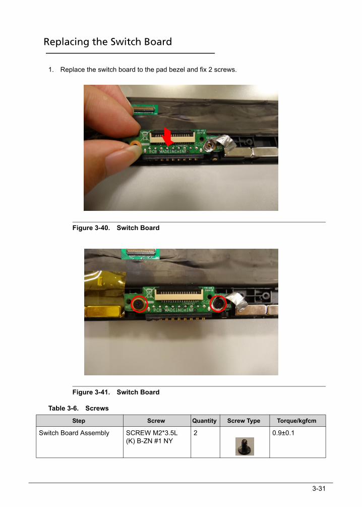
Replacing the Switch Board 0
1. Replace the switch board to the pad bezel and fix 2 screws.
Figure 3-40. Switch Board
Figure 3-41. Switch Board
Table 3-6. Screws
Step Screw Quantity Screw Type Torque/kgfcm
Switch Board Assembly SCREW M2*3.5L (K) B-ZN #1 NY
2 0.9±0.1
3-32
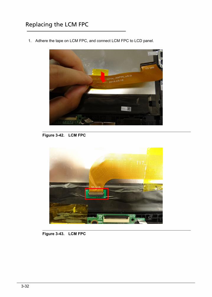
Replacing the LCM FPC 0
1. Adhere the tape on LCM FPC, and connect LCM FPC to LCD panel.
Figure 3-42. LCM FPC
Figure 3-43. LCM FPC

3-33
Replacing the Motherboard 0
1. Replace the main board to the pad bezel and set the microphone into its socket.
Figure 3-44. Motherboard
Figure 3-45. Motherboard
3-34
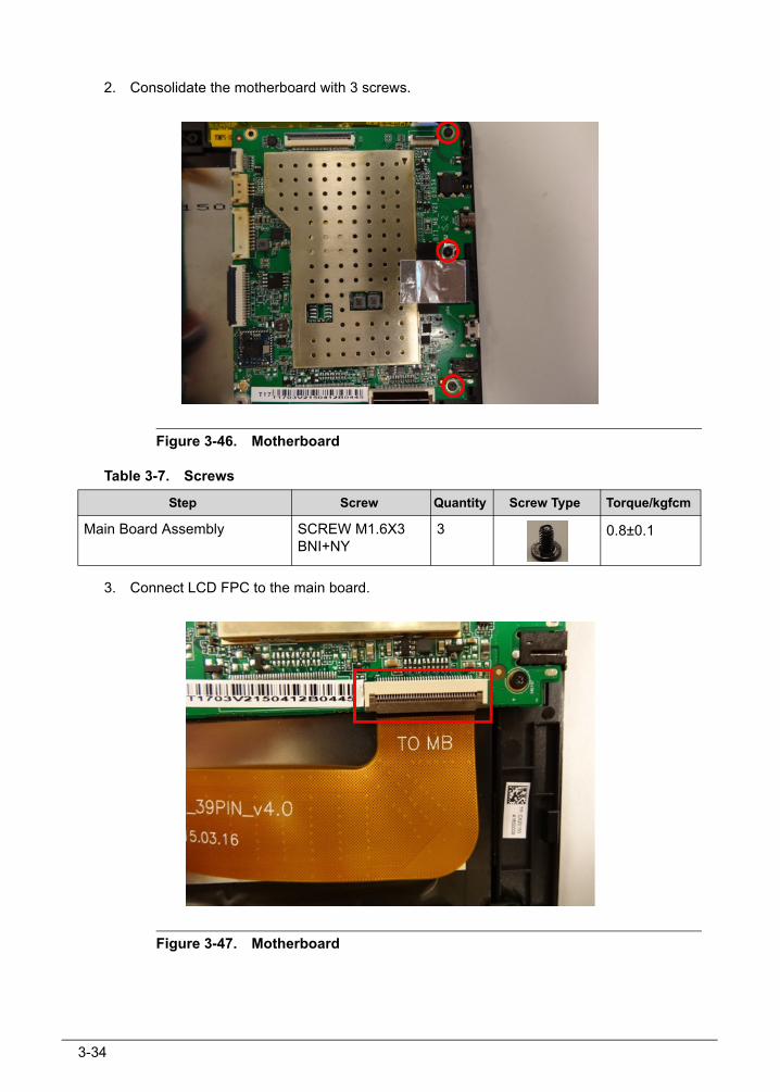
2. Consolidate the motherboard with 3 screws.
Figure 3-46. Motherboard
Table 3-7. Screws
3. Connect LCD FPC to the main board.
Figure 3-47. Motherboard
Step Screw Quantity Screw Type Torque/kgfcm
Main Board Assembly SCREW M1.6X3 BNI+NY
3 0.8±0.1
3-35
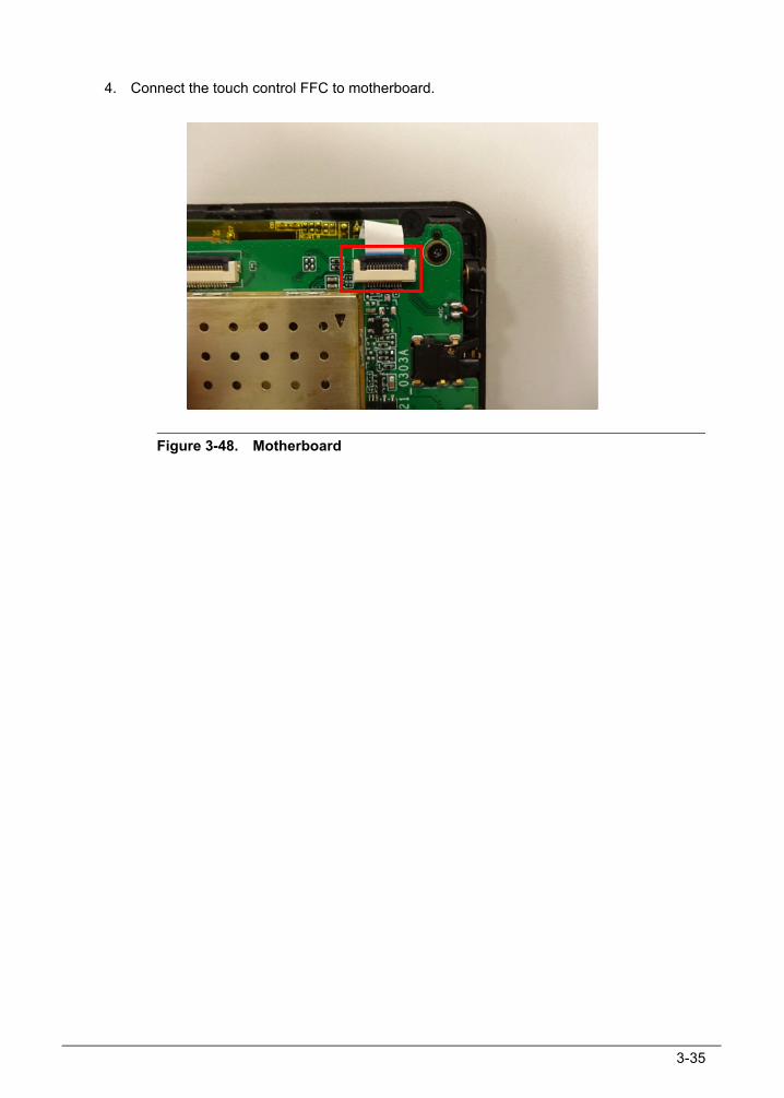
4. Connect the touch control FFC to motherboard.
Figure 3-48. Motherboard
3-36
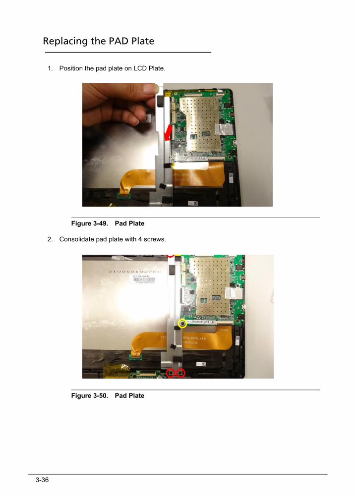
Replacing the PAD Plate 0
1. Position the pad plate on LCD Plate.
Figure 3-49. Pad Plate
2. Consolidate pad plate with 4 screws.
Figure 3-50. Pad Plate

3-37
Table 3-8. Screws
3. Adhere the tape on magnet.
Figure 3-51. Pad Plate
Step Screw Quantity Screw Type Torque/kgfcm
Pad Plate Assembly SCREW M1.6X3.5 BNI
3 0.9±0.1
SCREW M1.6X3 BNI+NY
1 0.8±0.1
3-38
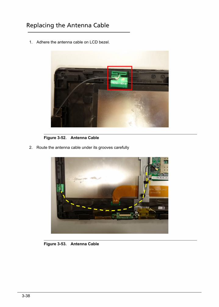
Replacing the Antenna Cable 0
1. Adhere the antenna cable on LCD bezel.
Figure 3-52. Antenna Cable
2. Route the antenna cable under its grooves carefully
Figure 3-53. Antenna Cable
3-39
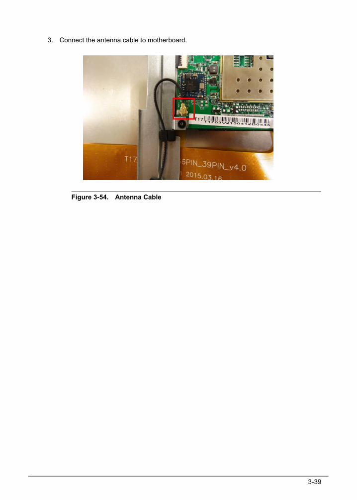
3. Connect the antenna cable to motherboard.
Figure 3-54. Antenna Cable
3-40
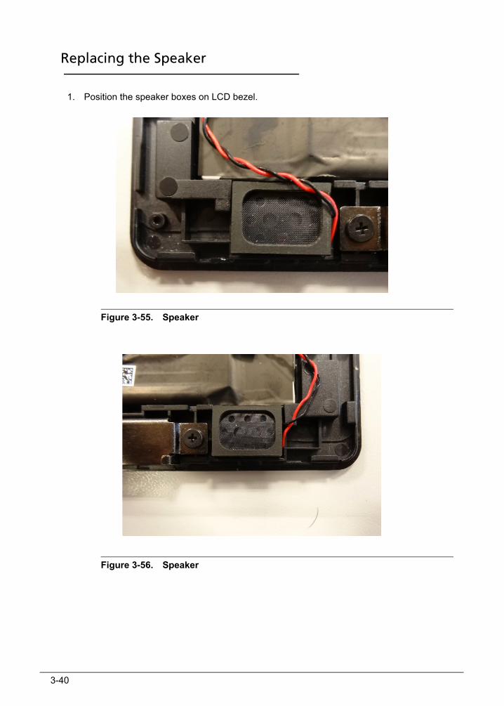
Replacing the Speaker 0
1. Position the speaker boxes on LCD bezel.
Figure 3-55. Speaker
Figure 3-56. Speaker
3-41
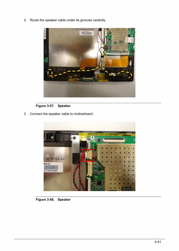
2. Route the speaker cable under its grooves carefully.
Figure 3-57. Speaker
3. Connect the speaker cable to motherboard.
Figure 3-58. Speaker
3-42
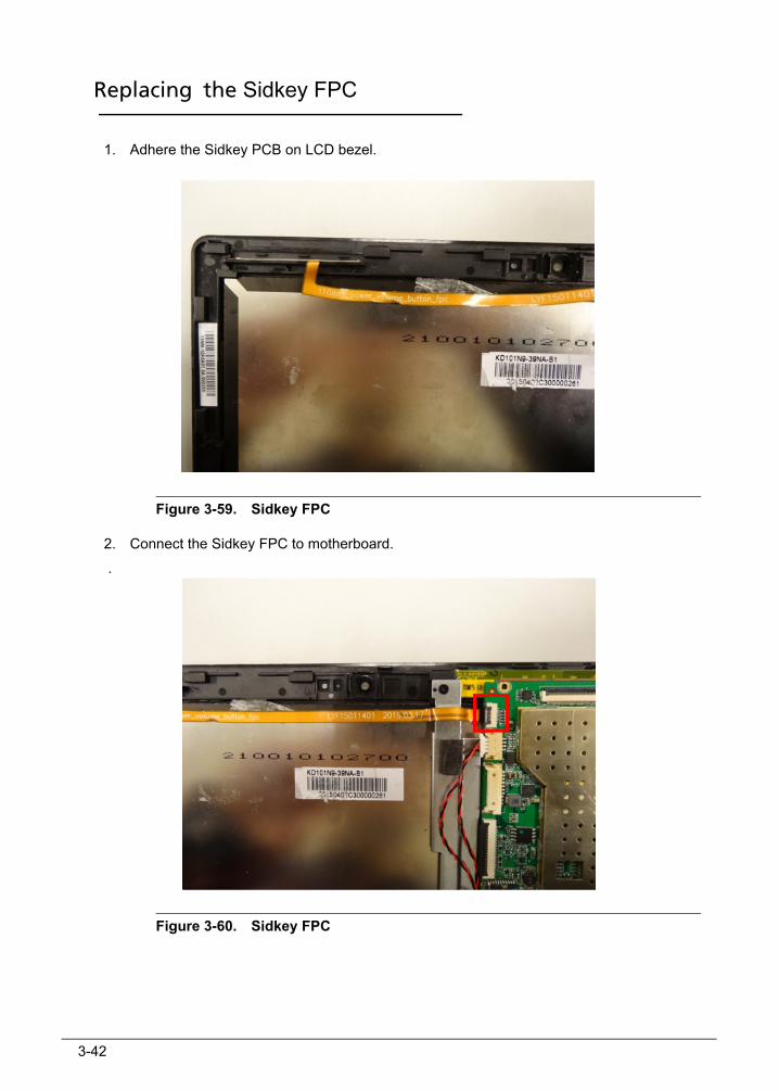
Replacing the Sidkey FPC 0
1. Adhere the Sidkey PCB on LCD bezel.
Figure 3-59. Sidkey FPC
2. Connect the Sidkey FPC to motherboard.
.
Figure 3-60. Sidkey FPC
3-43
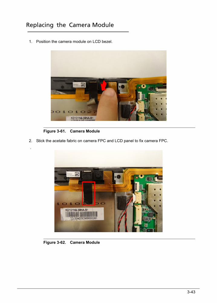
Replacing the Camera Module 0
1. Position the camera module on LCD bezel.
Figure 3-61. Camera Module
2. Stick the acetate fabric on camera FPC and LCD panel to fix camera FPC.
.
Figure 3-62. Camera Module
3-44
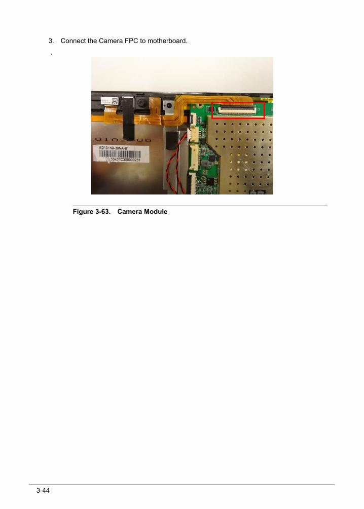
3. Connect the Camera FPC to motherboard.
.
Figure 3-63. Camera Module
3-45
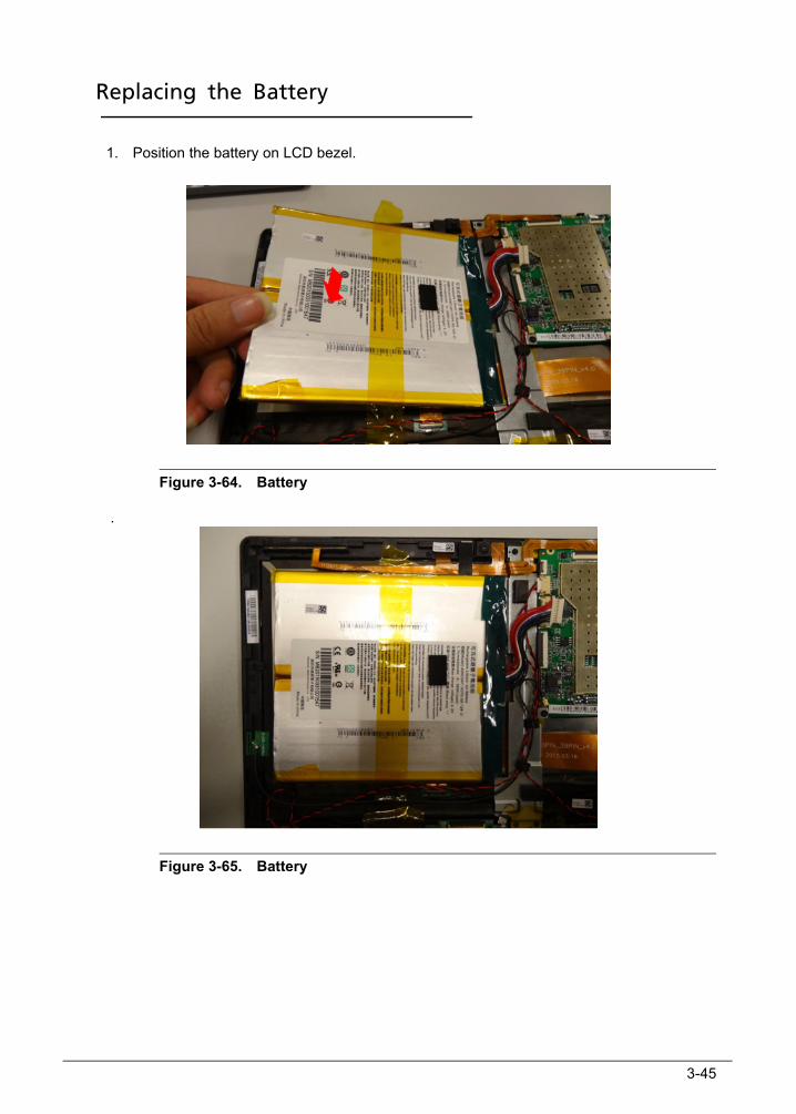
Replacing the Battery 0
1. Position the battery on LCD bezel.
Figure 3-64. Battery
.
Figure 3-65. Battery
3-46
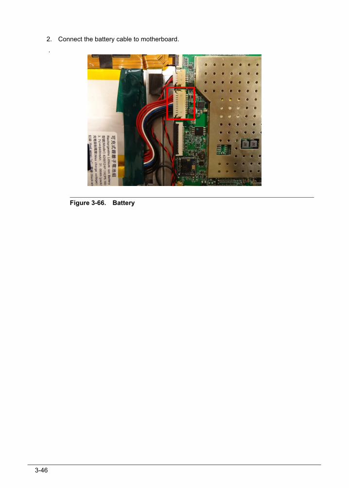
2. Connect the battery cable to motherboard.
.
Figure 3-66. Battery
3-47
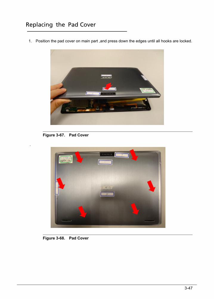
Replacing the Pad Cover 0
1. Position the pad cover on main part ,and press down the edges until all hooks are locked.
Figure 3-67. Pad Cover
.
Figure 3-68. Pad Cover
3-48
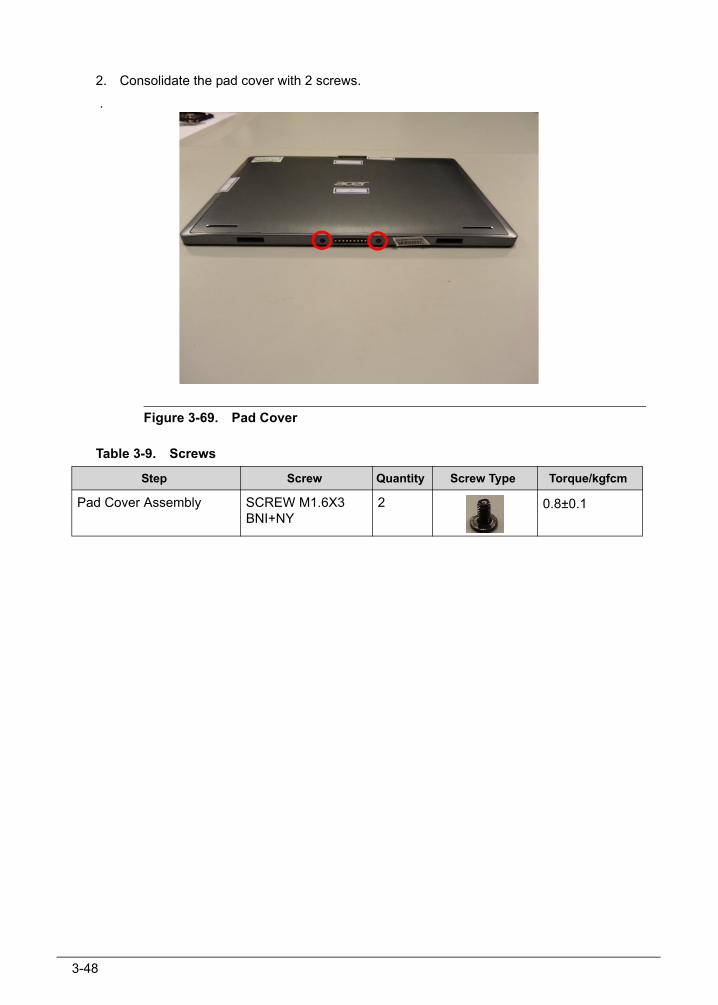
2. Consolidate the pad cover with 2 screws.
.
Figure 3-69. Pad Cover
Table 3-9. Screws
Step Screw Quantity Screw Type Torque/kgfcm
Pad Cover Assembly SCREW M1.6X3 BNI+NY
2 0.8±0.1
CHAPTER 6FRU List
6-4 FRU (Field Replaceable Unit) List
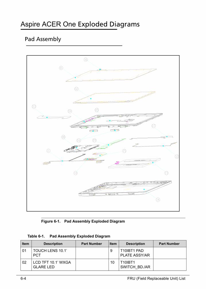
Aspire ACER One Exploded Diagrams 0
Pad Assembly 0
Figure 6-1. Pad Assembly Exploded Diagram
Table 6-1. Pad Assembly Exploded Diagram
Item Description Part Number Item Description Part Number
01 TOUCH LENS 10.1’ PCT
9 T10IBT1 PAD PLATE ASSY/AR
02 LCD TFT 10.1’ WXGA GLARE LED
10 T10IBT1 SWITCH_BD./AR
FRU (Field Replaceable Unit) List 6-5
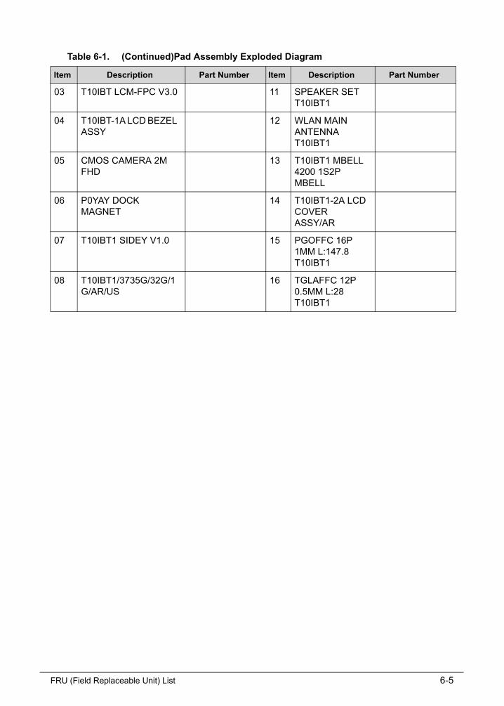
03 T10IBT LCM-FPC V3.0 11 SPEAKER SET T10IBT1
04 T10IBT-1A LCD BEZEL ASSY
12 WLAN MAIN ANTENNA T10IBT1
05 CMOS CAMERA 2M FHD
13 T10IBT1 MBELL 4200 1S2P MBELL
06 P0YAY DOCK MAGNET
14 T10IBT1-2A LCD COVER ASSY/AR
07 T10IBT1 SIDEY V1.0 15 PGOFFC 16P 1MM L:147.8 T10IBT1
08 T10IBT1/3735G/32G/1G/AR/US
16 TGLAFFC 12P 0.5MM L:28 T10IBT1
Table 6-1. (Continued)Pad Assembly Exploded Diagram
Item Description Part Number Item Description Part Number
6-6 FRU (Field Replaceable Unit) List
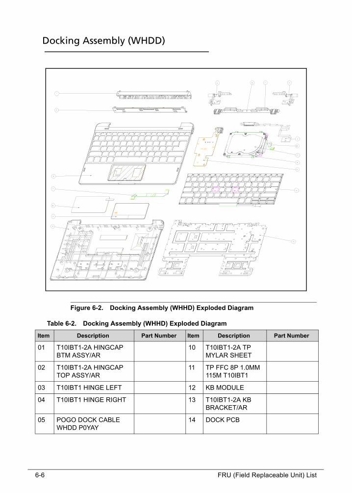
Docking Assembly (WHDD) 0
Figure 6-2. Docking Assembly (WHHD) Exploded Diagram
Table 6-2. Docking Assembly (WHHD) Exploded Diagram
Item Description Part Number Item Description Part Number
01 T10IBT1-2A HINGCAP BTM ASSY/AR
10 T10IBT1-2A TP MYLAR SHEET
02 T10IBT1-2A HINGCAP TOP ASSY/AR
11 TP FFC 8P 1.0MM 115M T10IBT1
03 T10IBT1 HINGE LEFT 12 KB MODULE
04 T10IBT1 HINGE RIGHT 13 T10IBT1-2A KB BRACKET/AR
05 POGO DOCK CABLE WHDD P0YAY
14 DOCK PCB

FRU (Field Replaceable Unit) List 6-7
06 T10IBT1-1A HINGE LINKBKT ASSY
15 T10IBT1-2A BTMCASE BLUE ASM/AR
07 P0YAY DOCK MAGNET 16 P0YAY HDD BRKT
08 T10IBT1-2A TOP CASE ASSY/AR
17 HDD MODULE
9 T10IBT1-2A TOUCHPAD MODULE/AR
18 HDD SATA FFC P0YCY
Item Description Part Number Item Description Part Number

6-8 FRU (Field Replaceable Unit) List
Docking Assembly (WOHDD) 0
Figure 6-3. Docking Assembly (WOHHD) Exploded Diagram
Table 6-3. Docking Assembly (WOHHD) Exploded Diagram
Item Description Part Number Item Description Part Number
01 T10IBT1-2A HINGCAP BTM ASSY/AR
10 T10IBT1-2A TP MYLAR SHEET
02 T10IBT1-2A HINGCAP TOP ASSY/AR
11 TP FFC 8P 1.0MM 115M T10IBT1
03 T10IBT1 HINGE LEFT 12 KB MODULE
04 T10IBT1 HINGE RIGHT 13 T10IBT1-2A KB BRACKET/AR
05 POGO DOCK CABLE WHDD P0YAY
14 DOCK PCB
06 T10IBT1-1A HINGE LINKBKT ASSY
15 T10IBT1-2A BTMCASE BLUE ASM/AR
FRU (Field Replaceable Unit) List 6-9
07 P0YAY DOCK MAGNET
08 T10IBT1-2A TOP CASE ASSY/AR
9 T10IBT1-2A TOUCHPAD MODULE/AR
Item Description Part Number Item Description Part Number
6-10 FRU (Field Replaceable Unit) List
FRU List 0
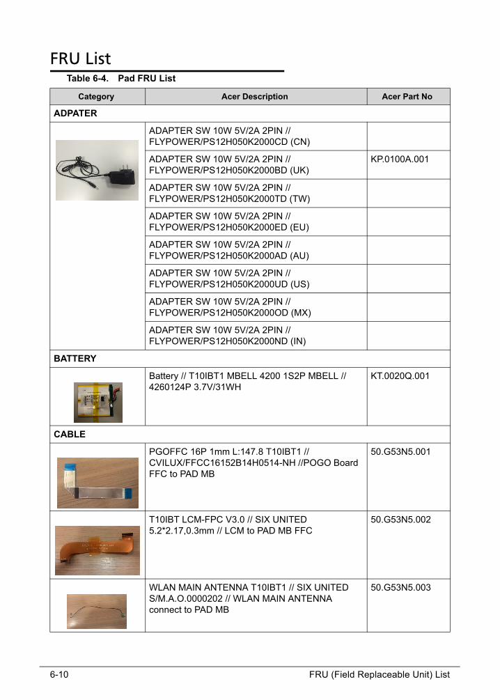
Table 6-4. Pad FRU List
Category Acer Description Acer Part No
ADPATER
ADAPTER SW 10W 5V/2A 2PIN // FLYPOWER/PS12H050K2000CD (CN)
ADAPTER SW 10W 5V/2A 2PIN // FLYPOWER/PS12H050K2000BD (UK)
KP.0100A.001
ADAPTER SW 10W 5V/2A 2PIN // FLYPOWER/PS12H050K2000TD (TW)
ADAPTER SW 10W 5V/2A 2PIN // FLYPOWER/PS12H050K2000ED (EU)
ADAPTER SW 10W 5V/2A 2PIN // FLYPOWER/PS12H050K2000AD (AU)
ADAPTER SW 10W 5V/2A 2PIN // FLYPOWER/PS12H050K2000UD (US)
ADAPTER SW 10W 5V/2A 2PIN // FLYPOWER/PS12H050K2000OD (MX)
ADAPTER SW 10W 5V/2A 2PIN // FLYPOWER/PS12H050K2000ND (IN)
BATTERY
Battery // T10IBT1 MBELL 4200 1S2P MBELL // 4260124P 3.7V/31WH
KT.0020Q.001
CABLE
PGOFFC 16P 1mm L:147.8 T10IBT1 // CVILUX/FFCC16152B14H0514-NH //POGO Board FFC to PAD MB
50.G53N5.001
T10IBT LCM-FPC V3.0 // SIX UNITED 5.2*2.17,0.3mm // LCM to PAD MB FFC
50.G53N5.002
WLAN MAIN ANTENNA T10IBT1 // SIX UNITED S/M.A.O.0000202 // WLAN MAIN ANTENNA connect to PAD MB
50.G53N5.003
FRU (Field Replaceable Unit) List 6-11
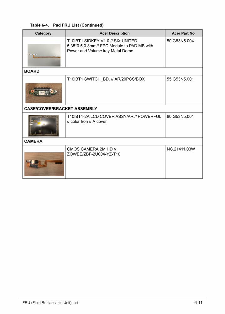
T10IBT1 SIDKEY V1.0 // SIX UNITED 5.35*0.5,0.3mm// FPC Module to PAD MB with Power and Volume key Metal Dome
50.G53N5.004
BOARD
T10IBT1 SWITCH_BD. // AR/20PCS/BOX 55.G53N5.001
CASE/COVER/BRACKET ASSEMBLY
T10IBT1-2A LCD COVER ASSY/AR // POWERFUL // color Iron // A cover
60.G53N5.001
CAMERA
CMOS CAMERA 2M HD // ZOWEE/ZBF-2U004-YZ-T10
NC.21411.03W
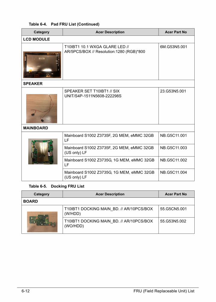
Table 6-4. Pad FRU List (Continued)
Category Acer Description Acer Part No
6-12 FRU (Field Replaceable Unit) List
LCD MODULE
T10IBT1 10.1 WXGA GLARE LED // AR/5PCS/BOX // Resolution:1280 (RGB)*800
6M.G53N5.001
SPEAKER
SPEAKER SET T10IBT1 // SIX UNIT/S4P-1511N5608-222298S
23.G53N5.001
MAINBOARD
Mainboard S1002 Z3735F, 2G MEM, eMMC 32GB LF
NB.G5C11.001
Mainboard S1002 Z3735F, 2G MEM, eMMC 32GB (US only) LF
NB.G5C11.003
Mainboard S1002 Z3735G, 1G MEM, eMMC 32GB LF
NB.G5C11.002
Mainboard S1002 Z3735G, 1G MEM, eMMC 32GB (US only) LF
NB.G5C11.004
Table 6-5. Docking FRU List
Category Acer Description Acer Part No
BOARD
T10IBT1 DOCKING MAIN_BD. // AR/10PCS/BOX (W/HDD)
55.G5CN5.001
T10IBT1 DOCKING MAIN_BD. // AR/10PCS/BOX (WO/HDD)
55.G53N5.002
Table 6-4. Pad FRU List (Continued)
Category Acer Description Acer Part No
FRU (Field Replaceable Unit) List 6-13
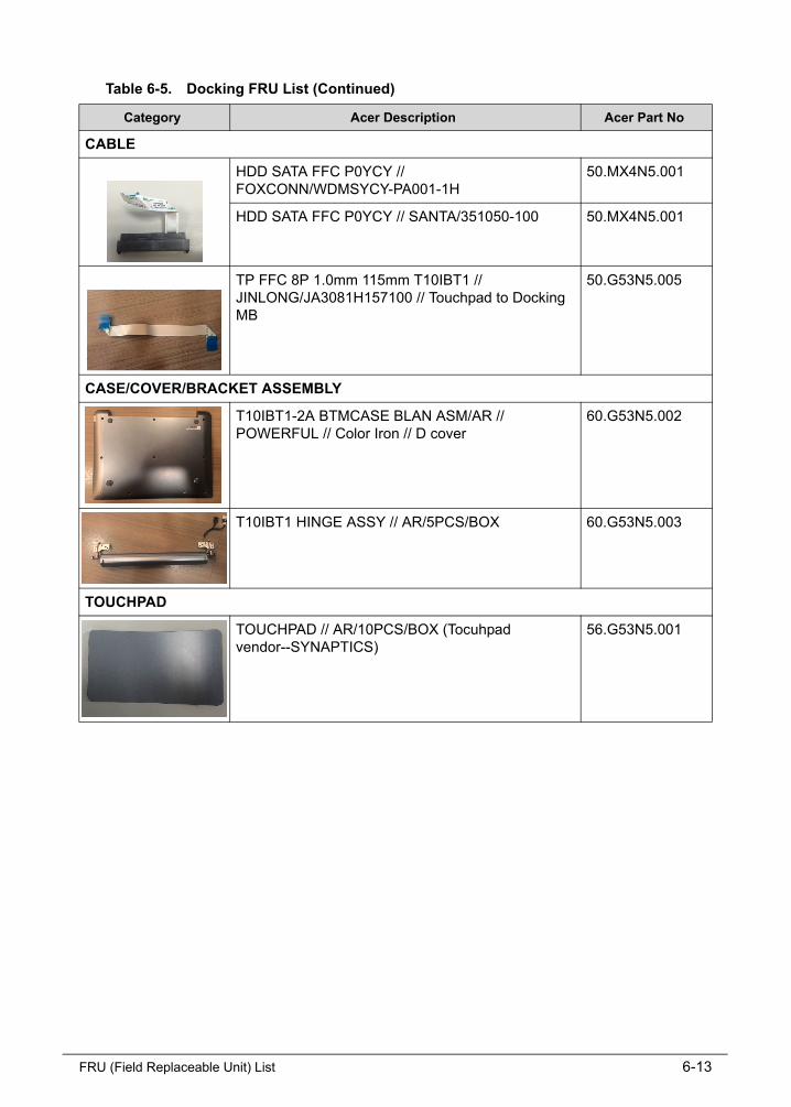
CABLE
HDD SATA FFC P0YCY // FOXCONN/WDMSYCY-PA001-1H
50.MX4N5.001
HDD SATA FFC P0YCY // SANTA/351050-100 50.MX4N5.001
TP FFC 8P 1.0mm 115mm T10IBT1 // JINLONG/JA3081H157100 // Touchpad to Docking MB
50.G53N5.005
CASE/COVER/BRACKET ASSEMBLY
T10IBT1-2A BTMCASE BLAN ASM/AR // POWERFUL // Color Iron // D cover
60.G53N5.002
T10IBT1 HINGE ASSY // AR/5PCS/BOX 60.G53N5.003
TOUCHPAD
TOUCHPAD // AR/10PCS/BOX (Tocuhpad vendor--SYNAPTICS)
56.G53N5.001
Table 6-5. Docking FRU List (Continued)
Category Acer Description Acer Part No