Disassembly Transferbelt ES281C
13
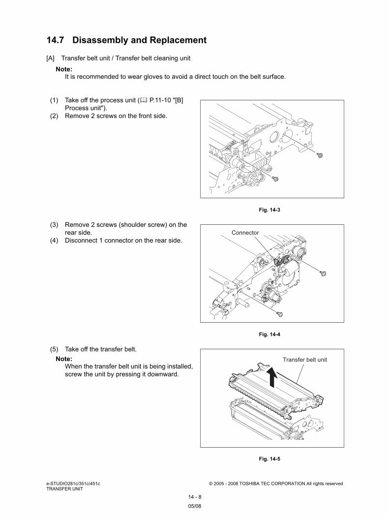
e-STUDIO281c/351c/451c © 2005 - 2008 TOSHIBA TEC CORPORATION All rights reserved TRANSFER UNIT 14 - 8 14.7 Disassembly and Replacement [A] Transfer belt unit / Transfer belt cleaning unit Note: It is recommended to wear gloves to avoid a direct touch on the belt surface. (1) Take off the process unit ( P.11-10 "[B] Process unit"). (2) Remove 2 screws on the front side. Fig. 14-3 (3) Remove 2 screws (shoulder screw) on the rear side. (4) Disconnect 1 connector on the rear side. Fig. 14-4 (5) Take off the transfer belt. Note: When the transfer belt unit is being installed, screw the unit by pressing it downward. Fig. 14-5 Connector Transfer belt unit 05/08
-
Upload
rickymaguigad -
Category
Documents
-
view
39 -
download
3
description
Disassemble Transferbelt ES281C Hope it helps
Transcript of Disassembly Transferbelt ES281C
e-STUDIO281c/351c/451c © 2005 - 2008 TOSHIBA TEC CORPORATION All rights reservedTRANSFER UNIT
14 - 8
14.7 Disassembly and Replacement
[A] Transfer belt unit / Transfer belt cleaning unit
Note: It is recommended to wear gloves to avoid a direct touch on the belt surface.
(1) Take off the process unit ( P.11-10 "[B] Process unit").
(2) Remove 2 screws on the front side.
Fig. 14-3
(3) Remove 2 screws (shoulder screw) on the rear side.
(4) Disconnect 1 connector on the rear side.
Fig. 14-4
(5) Take off the transfer belt.Note:
When the transfer belt unit is being installed, screw the unit by pressing it downward.
Fig. 14-5
Connector
Transfer belt unit
05/08
14
© 2005 - 2008 TOSHIBA TEC CORPORATION All rights reserved e-STUDIO281c/351c/451cTRANSFER UNIT
14 - 9
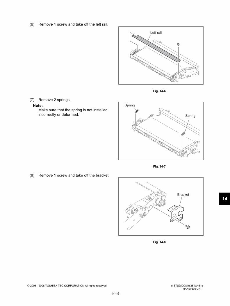
(6) Remove 1 screw and take off the left rail.
Fig. 14-6
(7) Remove 2 springs.Note:
Make sure that the spring is not installed incorrectly or deformed.
Fig. 14-7
(8) Remove 1 screw and take off the bracket.
Fig. 14-8
Left rail
Spring
Spring
Bracket

e-STUDIO281c/351c/451c © 2005 - 2008 TOSHIBA TEC CORPORATION All rights reservedTRANSFER UNIT
14 - 10
[B] Transfer belt
Note: It is recommended to wear gloves to avoid a direct touch on the belt surface.
(9) Take off the transfer belt cleaning unit.
Fig. 14-9
(1) Take off the transfer belt cleaning unit ( P.14-8 "[A] Transfer belt unit / Transfer belt cleaning unit").
(2) Remove 1 screw and take off the right rail.
Fig. 14-10
(3) Remove 1 screw on the front side and 1 screw on the rear side. Then lay down the tension roller.
Fig. 14-11
Transfer belt cleaning unit
Right rail
Screw
Screw
Tension roller
14
© 2005 - 2008 TOSHIBA TEC CORPORATION All rights reserved e-STUDIO281c/351c/451cTRANSFER UNIT
14 - 11
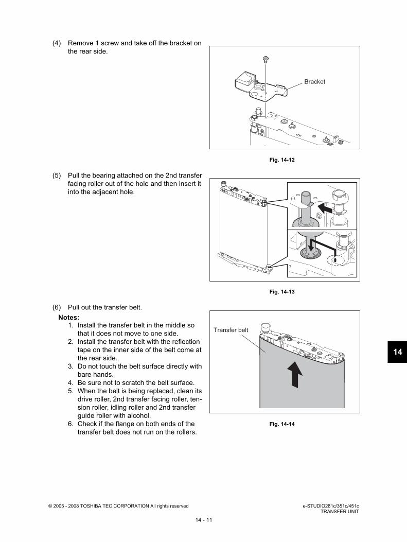
(4) Remove 1 screw and take off the bracket on the rear side.
Fig. 14-12
(5) Pull the bearing attached on the 2nd transfer facing roller out of the hole and then insert it into the adjacent hole.
Fig. 14-13
(6) Pull out the transfer belt.Notes:
1. Install the transfer belt in the middle so that it does not move to one side.
2. Install the transfer belt with the reflection tape on the inner side of the belt come at the rear side.
3. Do not touch the belt surface directly with bare hands.
4. Be sure not to scratch the belt surface.5. When the belt is being replaced, clean its
drive roller, 2nd transfer facing roller, ten-sion roller, idling roller and 2nd transfer guide roller with alcohol.
6. Check if the flange on both ends of the transfer belt does not run on the rollers.
Fig. 14-14
Bracket
Transfer belt

e-STUDIO281c/351c/451c © 2005 - 2008 TOSHIBA TEC CORPORATION All rights reservedTRANSFER UNIT
14 - 12
[C] 1st transfer roller
[D] Transfer belt home position sensor-1 (S15)
(1) Take off the transfer belt ( P.14-10 "[B] Transfer belt").
(2) Remove 1 screw.(3) Take off the holder on the rear side and take
off the 1st transfer roller.
Fig. 14-15
(1) Take off the transfer belt ( P.14-10 "[B] Transfer belt").
(2) Remove 1 screw and take off the cover.
Fig. 14-16
(3) Disconnect 1 connector and remove 1 screw. Then take off the transfer belt home position sensor-1.
Fig. 14-17
1st transfer roller
Holder
Screw
Cover
Transfer belt
home position sensor-1
14
© 2005 - 2008 TOSHIBA TEC CORPORATION All rights reserved e-STUDIO281c/351c/451cTRANSFER UNIT
14 - 13
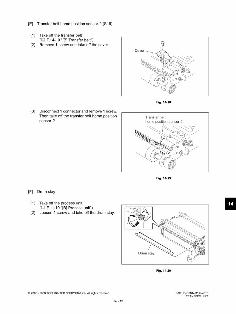
[E] Transfer belt home position sensor-2 (S16)
[F] Drum stay
(1) Take off the transfer belt ( P.14-10 "[B] Transfer belt").
(2) Remove 1 screw and take off the cover.
Fig. 14-18
(3) Disconnect 1 connector and remove 1 screw. Then take off the transfer belt home position sensor-2.
Fig. 14-19
(1) Take off the process unit ( P.11-10 "[B] Process unit").
(2) Loosen 1 screw and take off the drum stay.
Fig. 14-20
Cover
Transfer belt
home position sensor-2
Drum stay
e-STUDIO281c/351c/451c © 2005 - 2008 TOSHIBA TEC CORPORATION All rights reservedTRANSFER UNIT
14 - 14
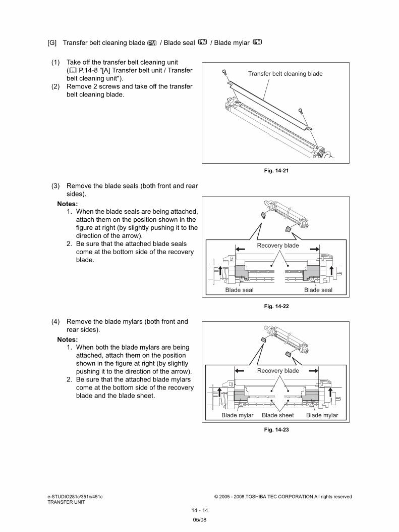
[G] Transfer belt cleaning blade / Blade seal / Blade mylar
(1) Take off the transfer belt cleaning unit ( P.14-8 "[A] Transfer belt unit / Transfer belt cleaning unit").
(2) Remove 2 screws and take off the transfer belt cleaning blade.
Fig. 14-21
(3) Remove the blade seals (both front and rear sides).
Notes: 1. When the blade seals are being attached,
attach them on the position shown in the figure at right (by slightly pushing it to the direction of the arrow).
2. Be sure that the attached blade seals come at the bottom side of the recovery blade.
Fig. 14-22
(4) Remove the blade mylars (both front and rear sides).
Notes: 1. When both the blade mylars are being
attached, attach them on the position shown in the figure at right (by slightly pushing it to the direction of the arrow).
2. Be sure that the attached blade mylars come at the bottom side of the recovery blade and the blade sheet.
Fig. 14-23
Transfer belt cleaning blade
Blade sealBlade seal
Recovery blade
Blade sheet Blade mylarBlade mylar
Recovery blade
05/08
14
© 2005 - 2008 TOSHIBA TEC CORPORATION All rights reserved e-STUDIO281c/351c/451cTRANSFER UNIT
14 - 15
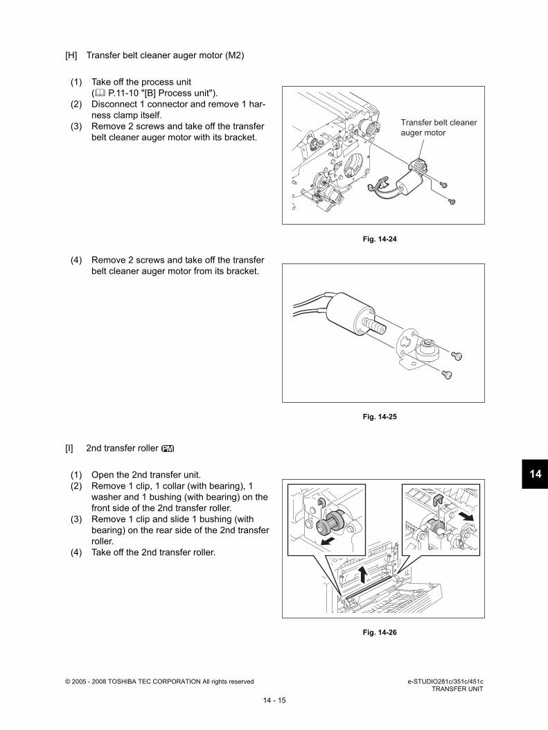
[H] Transfer belt cleaner auger motor (M2)
[I] 2nd transfer roller
(1) Take off the process unit ( P.11-10 "[B] Process unit").
(2) Disconnect 1 connector and remove 1 har-ness clamp itself.
(3) Remove 2 screws and take off the transfer belt cleaner auger motor with its bracket.
Fig. 14-24
(4) Remove 2 screws and take off the transfer belt cleaner auger motor from its bracket.
Fig. 14-25
(1) Open the 2nd transfer unit.(2) Remove 1 clip, 1 collar (with bearing), 1
washer and 1 bushing (with bearing) on the front side of the 2nd transfer roller.
(3) Remove 1 clip and slide 1 bushing (with bearing) on the rear side of the 2nd transfer roller.
(4) Take off the 2nd transfer roller.
Fig. 14-26
Transfer belt cleaner
auger motor

e-STUDIO281c/351c/451c © 2005 - 2008 TOSHIBA TEC CORPORATION All rights reservedTRANSFER UNIT
14 - 16
[J] 2nd transfer unit
(5) Remove 1 clip, 1 collar (with bearing), 1 washer, 1 holder and 1 bushing (with bear-ing) from the rear side of the 2nd transfer roller.
Note: A spring is fit in the holder. When the roller is reassembled, make sure that the spring is not installed incorrectly or deformed.
Fig. 14-27
(1) Take off the right front hinge cover ( P.2-28 "[I] Right front hinge cover").
(2) Remove 2 screws and take off the hinge pin.
Fig. 14-28
(3) Open the 2nd transfer unit. (4) Disconnect 1 connector and release the har-
ness clamp.(5) Remove 3 screws and take off the 2nd trans-
fer gear unit.
Fig. 14-29
Clip
Collar
Holder
Bushing
2nd transfer roller
Washer
Hinge pin
Gear unit

14
© 2005 - 2008 TOSHIBA TEC CORPORATION All rights reserved e-STUDIO281c/351c/451cTRANSFER UNIT
14 - 17
[K] Case
(6) Take off the 2nd transfer unit.
Fig. 14-30
(1) Take off the 2nd transfer unit ( P.14-16 "[J] 2nd transfer unit").
(2) Take off the 2nd transfer roller ( P.14-15 "[I] 2nd transfer roller").
(3) Remove 2 screws and take off the pre-trans-fer guide.
Fig. 14-31
Note: When the pre-transfer guide is being installed, be sure that 3 tabs of the guide come underneath the bracket (metal plate).
Fig. 14-32
2nd transfer roller
Pre-transfer guide
05/08
e-STUDIO281c/351c/451c © 2005 - 2008 TOSHIBA TEC CORPORATION All rights reservedTRANSFER UNIT
14 - 18
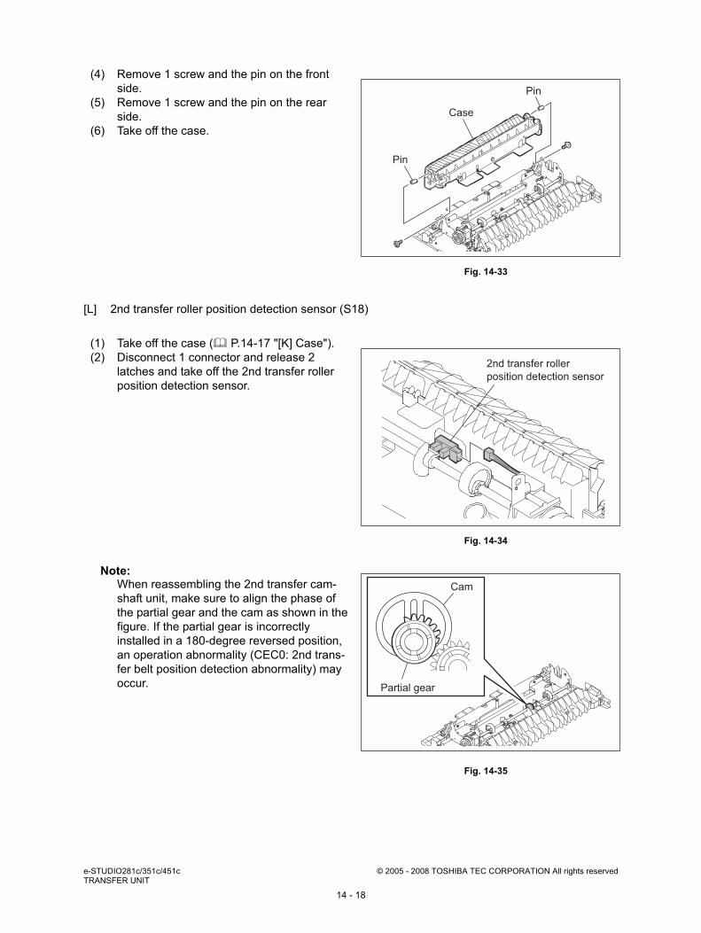
[L] 2nd transfer roller position detection sensor (S18)
(4) Remove 1 screw and the pin on the front side.
(5) Remove 1 screw and the pin on the rear side.
(6) Take off the case.
Fig. 14-33
(1) Take off the case ( P.14-17 "[K] Case").(2) Disconnect 1 connector and release 2
latches and take off the 2nd transfer roller position detection sensor.
Fig. 14-34
Note: When reassembling the 2nd transfer cam-shaft unit, make sure to align the phase of the partial gear and the cam as shown in the figure. If the partial gear is incorrectly installed in a 180-degree reversed position, an operation abnormality (CEC0: 2nd trans-fer belt position detection abnormality) may occur.
Fig. 14-35
Pin
Pin
Case
2nd transfer roller
position detection sensor
Cam
Partial gear
14
© 2005 - 2008 TOSHIBA TEC CORPORATION All rights reserved e-STUDIO281c/351c/451cTRANSFER UNIT
14 - 19
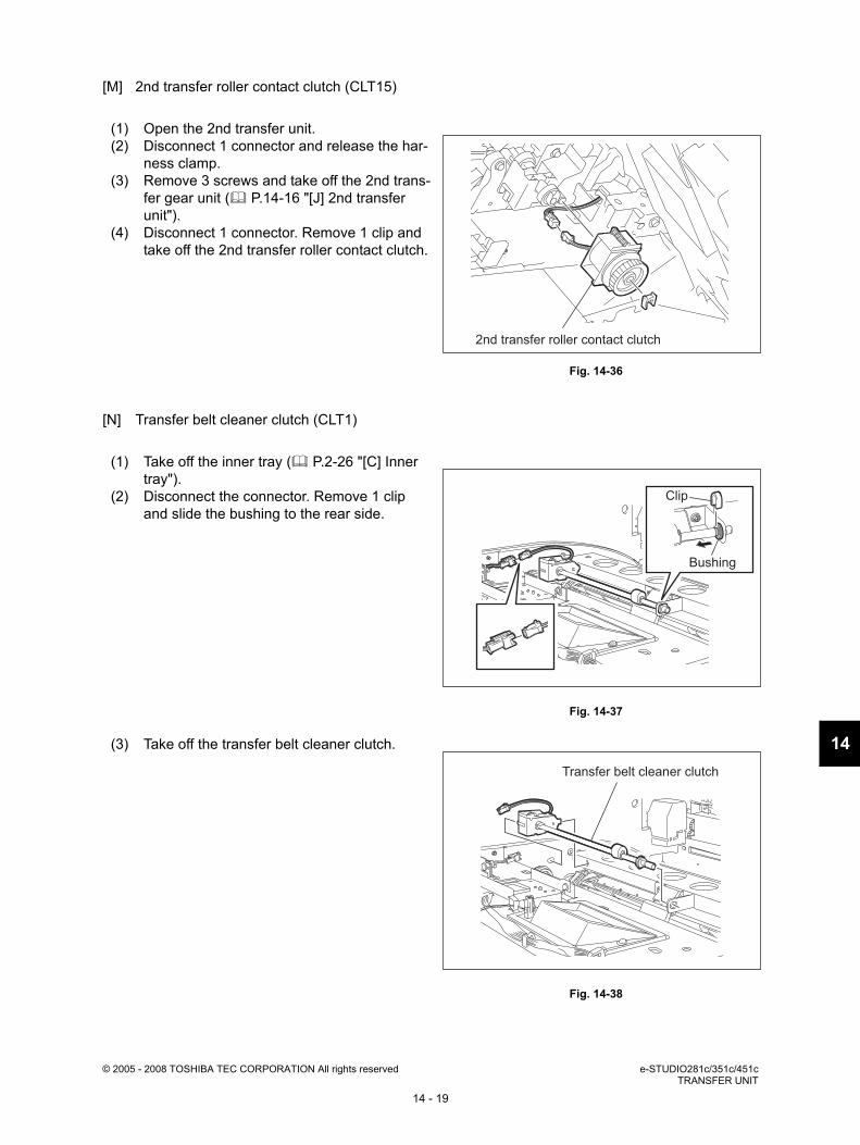
[M] 2nd transfer roller contact clutch (CLT15)
[N] Transfer belt cleaner clutch (CLT1)
(1) Open the 2nd transfer unit.(2) Disconnect 1 connector and release the har-
ness clamp.(3) Remove 3 screws and take off the 2nd trans-
fer gear unit ( P.14-16 "[J] 2nd transfer unit").
(4) Disconnect 1 connector. Remove 1 clip and take off the 2nd transfer roller contact clutch.
Fig. 14-36
(1) Take off the inner tray ( P.2-26 "[C] Inner tray").
(2) Disconnect the connector. Remove 1 clip and slide the bushing to the rear side.
Fig. 14-37
(3) Take off the transfer belt cleaner clutch.
Fig. 14-38
2nd transfer roller contact clutch
Clip
Bushing
Transfer belt cleaner clutch

e-STUDIO281c/351c/451c © 2005 - 2008 TOSHIBA TEC CORPORATION All rights reservedTRANSFER UNIT
14 - 20