PRC8100724 Condensatori Centrifughi - unicond.ru · CONTE NTS WARNINGS (also the part ded icated to...
108
B B B R R R A A A C C C ( 2 2 9 9 8 8 – – 7 7 4 4 6 6 k kW W) AIR-COOLED WATER CHILLERS 1206A – 1306A – 1506A – 1802A – 2002A – 2202A – 2502A – 2802A – 3002A B B R R A A T T ( ( 3 3 1 1 7 7 – – 7 7 4 4 6 6 k k W W ) ) AIR-COOLED WATER CHILLERS FOR HIGH EXTERNAL TEMPERATURES 1206A – 1306A – 1506A – 1802A – 2002A – 2202A – 2502A – 2802A – 3002A B B R R A A F F ( ( 2 2 9 9 0 0 – – 7 7 2 2 4 4 k k W W ) ) AIR-COOLED WATER CHILLERS WITH FREE-COOLING SYSTEM 1206A – 1306A – 1506A – 1802A – 2002A – 2202A – 2502A – 2802A – 3002A B B R R A A M M ( ( 2 2 7 7 1 1 – – 6 6 1 1 0 0 k k W W ) ) ULTRA-LOW NOISE AIR-COOLED WATER CHILLERS WITH FREE-COOLING SYSTEM 1206A – 1306A – 1506A – 1802A – 2002A – 2202A – 2502A – 2802A – 3002A INSTRUCTION MANUAL IMPORTANT: This manual is protected by copyright laws. The distribution of this information to unauthorised persons and the reproduction, even in part, of this manual is therefore prohibited.
Transcript of PRC8100724 Condensatori Centrifughi - unicond.ru · CONTE NTS WARNINGS (also the part ded icated to...
BBBRRRAAACCC (229988 –– 774466 kkWWW) AIR-COOLED WATER CHILLERS
1206A – 1306A – 1506A – 1802A – 2002A – 2202A – 2502A – 2802A – 3002A
BBBRRRAAATTT (((333111777 ––– 777444666 kkkWWW))) AIR-COOLED WATER CHILLERS FOR HIGH EXTERNAL TEMPERATURES
1206A – 1306A – 1506A – 1802A – 2002A – 2202A – 2502A – 2802A – 3002A
BBBRRRAAAFFF (((222999000 ––– 777222444 kkkWWW))) AIR-COOLED WATER CHILLERS WITH FREE-COOLING SYSTEM
1206A – 1306A – 1506A – 1802A – 2002A – 2202A – 2502A – 2802A – 3002A
BBBRRRAAAMMM (((222777111 ––– 666111000 kkkWWW))) ULTRA-LOW NOISE AIR-COOLED WATER CHILLERS WITH FREE-COOLING SYSTEM
1206A – 1306A – 1506A – 1802A – 2002A – 2202A – 2502A – 2802A – 3002A
INSTRUCTION MANUAL
IMPORTANT: This manual is protected by copyright laws. The distribution of this information to unauthorised persons
and the reproduction, even in part, of this manual is therefore prohibited.

Release: 01.1
Date: 07.05.2004
Checked by:
2 Versione 01.1 del 07.05.2004
UNIFLAIR SpA policy is one of continuous technological innovation and the Company therefore reserves the right to amend any data herein without prior notice.
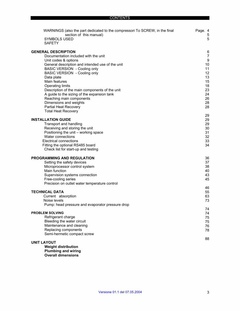
CONTENTS
WARNINGS (also the part dedicated to the compressori To SCREW, in the final section of this manual)
SYMBOLS USED SAFETY
Page. 4 5 5
GENERAL DESCRIPTION Documentation included with the unit Unit codes & options General description and intended use of the unit BASIC VERSION - Cooling only BASIC VERSION - Cooling only Data plate Main features Operating limits Description of the main components of the unit A guide to the sizing of the expansion tank Reaching main components Dimensions and weights Partial Heat Recovery Total Heat Recovery
INSTALLATION GUIDE
Transport and handling Receiving and storing the unit Positioning the unit – working space Water connections
Electrical connections Fitting the optional RS485 board Check list for start-up and testing
6 7 9
10 11 12 13 15 18 23 24 26 28 28 29 29 29 30 31 32 33 34
PROGRAMMING AND REGULATION Setting the safety devices Microprocessor control system Main function Supervision systems connection Free-cooling series Precision on outlet water temperature control
TECHNICAL DATA
Current absorption Noise levels Pump: head pressure and evaporator pressure drop
PROBLEM SOLVING
Refrigerant charge Bleeding the water circuit Maintenance and cleaning Replacing components Semi-hermetic compact screw
UNIT LAYOUT
Weight distribution Plumbing and wiring Overall dimensions
36 37 38 40 43 45 46 55 63 73 74 74 75 75 76 78 88
Versione 01.1 del 07.05.2004 3

This unit has been subjected to risk analysis under EC Directive 98/37/CEE (89/392/CEE). The technical solutions implemented during the design phase are described in the unit’s technical file.
This equipment is manufactured to function safely for the purposes for which it was designed as long as the installation, operation and maintenance are carried out according to the instructions in this manual and on the labels attached to the unit.
Warnings in this manual which are particularly important for user safety are shown by this danger symbol.
If the instructions herein are NOT complied with, the warranty shall be void.
IMPORTANT WARNINGS
This unit contains refrigerant gas circuits, chilled water under pressure, live electrical components, hot surfaces, sharp edges (the fins on the coils) and rotating devices such as the fans. All service and maintenance operations which require access to the inside of the unit while it is in operation must be performed by qualified and experienced personnel who are aware of the necessary precautions.
Before accessing the inside of the unit, disconnect it from the electrical power supply.
In any case, all safety legislation of the installation location must be followed.
In the event of fire water and other conductive substances must not be used to put out the fire near live electrical components. This warning must be displayed on notices in the unit installation location.
If the refrigerants used come into contact with fire they decompose, forming acids and other irritants. The smell of these substances, even at concentrations below danger levels, gives enough warning to allow evacuation of the area at risk.
Make sure that the mains supply to the unit is the same as that shown on the rating plate.
Drain all water from the system before the winter season to avoid freezing. In periods in which the temperature may fall below 0°C, empty the unit in order to prevent the serious damage caused by the formation of ice. This precaution is not necessary if the unit is charged with an appropriate anti-freeze mixture.
Free cooling chillers must be loaded with anti-freeze. If the unit is fitted with the optional heating cable, it must be turned off without cutting the electrical power supply.
Install a mechanical filter in the section of tubing near the intake of the unit to prevent the fouling of the heat exchanger with pieces of welding or flakes of oxidised metal from the water mains.
“In compliance with Community directive 94/9/CE these units are not to be used in potentially explosive environments”.
4 Versione 01.1 del 07.05.2004

SYMBOLS USED
SYMBOL MEANING SYMBOL MEANING DANGER MOVING COMPONENTS
IMPORTANT WARNING HOT SURFACES – DANGER OF BURNING
HIGH VOLTAGE – ELECTRICAL RISK
SHARP EDGES
SAFETY
The new range of AQUAFLAIR water chillers and heat pumps features state-of-the-art technology to give maximum reliability, safety, quietness of operation and respect for the environment.
1) RELIABILITY: Trouble-free operation of Uniflair precision chillers is ensured by rigorous production process controls under ISO 9001-certified quality procedures: • quality control of components; • pressure testing of refrigerant and water circuits; • testing of current absorption and IEC safety testing; • calibration and testing of instruments and safety devices; • final testing of unit under operating conditions
2) ACTIVE SAFETY: UNIFLAIR safety and control systems have a supervision and prevention function with: • automatic blocking of components in dangerous conditions; • indication of function status; reading and continuous display of circulating fluid temperature; • management of compressor start-ups to reduce excessive switching on and off • compressor start timing to reduce total unit start-up current • indication of anomalous function conditions and/or alarms.
3) PASSIVE SAFETY: The essential functions of UNIFLAIR chillers are protected against anomalous function conditions and potential damage with: • high and low pressostats on the refrigerant circuit (HP with manual re-set) • safety valve on the high pressure refrigerant line • anti-freeze protection to prevent freezing of the evaporator, pump and tank • compressor motor electrical protection • water circuit safety (with optional pump group) • compressor crankcase heater (standard on free-cooling and heat pump versions).
4) PERSONAL SAFETY. The design and cabling of all UNIFLAIR chillers conforms to IEC electro- technical norms. Electrical panels have auxiliary 24V circuits and are equipped with: • general switch and door lock switch; • automatic circuit-breaker switches; • double protection panel on fan compartment.
The fans inlet end outlet are protected by an external metal grille which conforms toapplicable safety norms.
Versione 01.1 del 07.05.2004 5
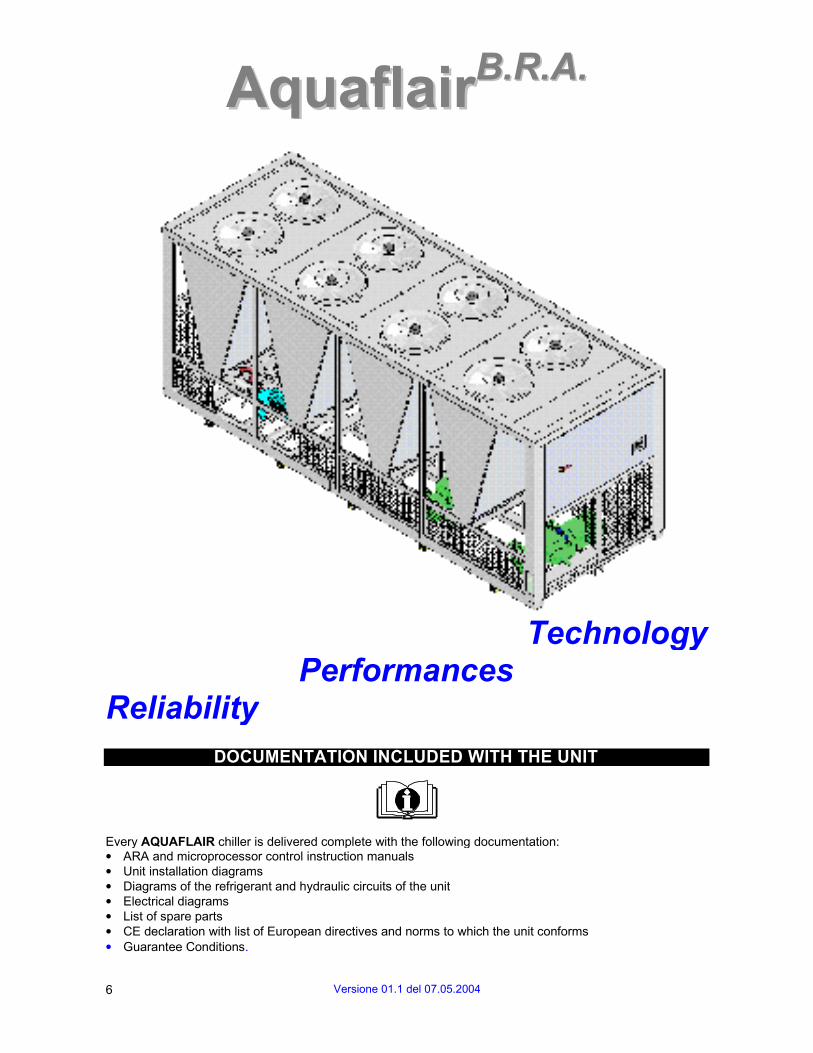
AAqquuaaffllaaiirrBB..RR..AA..
Reliability Performances
Technology
DOCUMENTATION INCLUDED WITH THE UNIT
Every AQUAFLAIR chiller is delivered complete with the following documentation: • ARA and microprocessor control instruction manuals • Unit installation diagrams • Diagrams of the refrigerant and hydraulic circuits of the unit • Electrical diagrams • List of spare parts • CE declaration with list of European directives and norms to which the unit conforms • Guarantee Conditions.
6 Versione 01.1 del 07.05.2004

UNIT CODES & OPTIONS
BRAC – cooling only series • Basic version (*) • Low noise version (*): constructed by limiting fan speed and by reducing the noise level of compressors, using
sound-proofing of compressors (Scroll) or sound-proofed casing and vibration dampers for screw compressors.
BRAT – cooling only series for high temperatures • Basic version (*) • Low noise version (*): constructed by limiting fan speed and by reducing the noise level of compressors, using
sound-proofing of compressors (Scroll) or sound-proofed casing and vibration dampers for screw compressors; • Ultra-low noise version: constructed by limiting fan speed and by reducing the noise level of compressors, using
sound-proofing of compressors (Scroll) or sound-proofed casing and vibration dampers for screw compressors(speed controller on all fans as standard).
BRAF – free-cooling series • Basic version with speed controller on all fans • Low noise version: constructed by limiting fan speed and by reducing the noise level of compressors, using
sound-proofing of compressors (Scroll) or sound-proofed casing and vibration dampers for screw compressors(speed controller on all fans as standard)
BRAM – Ultra-low noise free-cooling series • Basic version: constructed by ultra limiting fan speed and by reducing the noise level of compressors, using
sound-proofing of compressors (Scroll) or sound-proofed casing and vibration dampers for screw compressors(speed controller on all fans as standard)
(*) speed controller on a group of fans
New series can be equipped with: • Low external temperature configuration (down to –20°) (Std. for BRAT ultra-low noise version or
BRAF-M series) • Partial heat recovery • Total heat recovery (available only for BRAC and BRAT)
• Low temperature water production (down to –10°) • Continuous regulation of outlet water temperature • Remote water sensor
• Pump group: 1 pump • Pump group: 1+1 pumps
• R407C • R134a (on request) • R22 (**) (on request) (**) For Countries belonging to the European Union, in accordance with European Council standards CE 2037/00, all models areequipped with refrigerant model R407C.
Versione 01.1 del 07.05.2004 7
UNIT CODES & OPTIONS
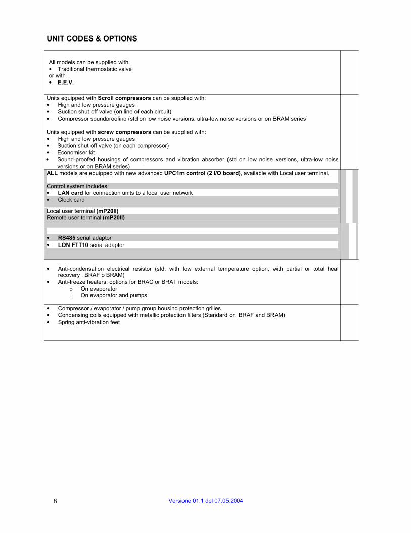
All models can be supplied with: • Traditional thermostatic valve or with • E.E.V.
Units equipped with Scroll compressors can be supplied with: • High and low pressure gauges • Suction shut-off valve (on line of each circuit) • Compressor soundproofing (std on low noise versions, ultra-low noise versions or on BRAM series)
Units equipped with screw compressors can be supplied with: • High and low pressure gauges • Suction shut-off valve (on each compressor) • Economiser kit • Sound-proofed housings of compressors and vibration absorber (std on low noise versions, ultra-low noise
versions or on BRAM series) ALL models are equipped with new advanced UPC1m control (2 I/O board), available with Local user terminal.
Control system includes: • LAN card for connection units to a local user network• Clock card
Local user terminal (mP20II) Remote user terminal (mP20II)
• RS485 serial adaptor • LON FTT10 serial adaptor
• Anti-condensation electrical resistor (std. with low external temperature option, with partial or total heatrecovery , BRAF o BRAM)
• Anti-freeze heaters: options for BRAC or BRAT models: o On evaporator o On evaporator and pumps
• Compressor / evaporator / pump group housing protection grilles • Condensing coils equipped with metallic protection filters (Standard on BRAF and BRAM)• Spring anti-vibration feet
8 Versione 01.1 del 07.05.2004
AAqquuaaffllaaiirrBB..RR..AA..
AQUAFLAIR B.R.A. is the new range of UNIFLAIR chillers, created according to new, unique
flexibility criteria. Nine air-cooled models with hermetic scroll compressors, or semi-hermetic screw compressors, plus axial fans, with nominal cooling capacity from 300 to 750 kW, available in four series:
- cooling only - cooling only for high ambient temperatures - free-cooling - ultra-low noise free-cooling
Our commitment to respect the environmental regulations, a commitment typical of UNIFLAIR products, is fully adhered to in these new series too. The series were designed for standard operation with refrigerant R407C and R134a (on request, R22 as well).
As we were looking to base the AQUAFLAIR B.R.A. series on cutting-edge technology, this led us to include many features and details. The basic version already includes a unit with a fan speed regulator, and, as optional items, an electronic thermostatic valve, and the economiserkit, to maximise performance and minimise operating costs.
Everything is controlled by the UPC1m control system: two I/O boards connected to the mP20II user interface, for full control of the all the unit's parameters. There are more items to complete the hardware: a LAN card and a clock card, both standard items, and the serial RS485 adapter (optional) for connection to the Uniflair supervision system or to o Building Management System. The AQUAFLAIR B.R.A. series models are top-of-the range in terms of technological design criterion, and flexibility. You can always chose the configuration suitable for each application, by highly restricting the range of outlet water temperature, thanks to partial (6 step in the 6-Scroll compressors unit or 8 steps in the 2-screw compressor models) or continuous control of compressors (unit with screw compressors).
The refrigerators can be supplied in low-noise or ultra low-noise versions, recording noise emission values among the lowest in the category.
As these new units cover a very broad outside temperature range, thanks to the series for high external temperatures (up to 50°C) and to the low external temperature option (down to –20°C), they can be used in all ambient conditions.
A great deal of attention was addressed to installation as well: the units can be supplied with 1 or 2 on-board pumps. All this makes the AQUAFLAIR B.R.A.
series true plug-and-play machines.
Versione 01.1 del 07.05.2004 9
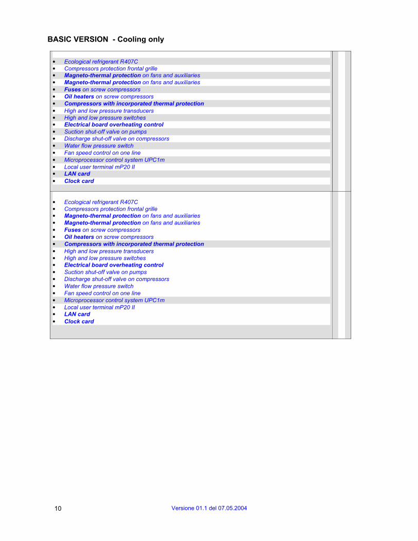
BASIC VERSION - Cooling only
• Ecological refrigerant R407C • Compressors protection frontal grille • Magneto-thermal protection on fans and auxiliaries • Magneto-thermal protection on fans and auxiliaries • Fuses on screw compressors • Oil heaters on screw compressors • Compressors with incorporated thermal protection • High and low pressure transducers • High and low pressure switches • Electrical board overheating control • Suction shut-off valve on pumps • Discharge shut-off valve on compressors • Water flow pressure switch • Fan speed control on one line • Microprocessor control system UPC1m • Local user terminal mP20 II • LAN card • Clock card
• Ecological refrigerant R407C • Compressors protection frontal grille • Magneto-thermal protection on fans and auxiliaries • Magneto-thermal protection on fans and auxiliaries • Fuses on screw compressors • Oil heaters on screw compressors • Compressors with incorporated thermal protection • High and low pressure transducers • High and low pressure switches • Electrical board overheating control • Suction shut-off valve on pumps • Discharge shut-off valve on compressors • Water flow pressure switch • Fan speed control on one line • Microprocessor control system UPC1m • Local user terminal mP20 II • LAN card • Clock card
10 Versione 01.1 del 07.05.2004
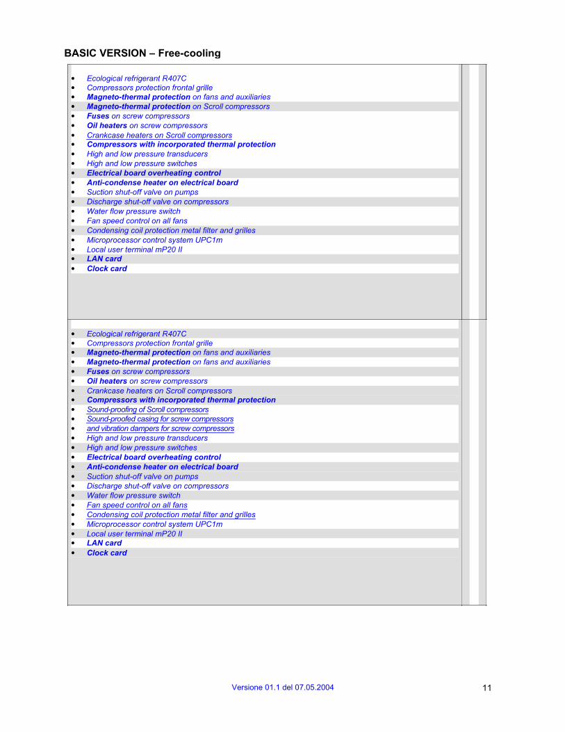
BASIC VERSION – Free-cooling
• Ecological refrigerant R407C • Compressors protection frontal grille • Magneto-thermal protection on fans and auxiliaries • Magneto-thermal protection on Scroll compressors • Fuses on screw compressors • Oil heaters on screw compressors • Crankcase heaters on Scroll compressors • Compressors with incorporated thermal protection • High and low pressure transducers • High and low pressure switches • Electrical board overheating control • Anti-condense heater on electrical board • Suction shut-off valve on pumps • Discharge shut-off valve on compressors • Water flow pressure switch • Fan speed control on all fans • Condensing coil protection metal filter and grilles • Microprocessor control system UPC1m • Local user terminal mP20 II • LAN card • Clock card
• Ecological refrigerant R407C • Compressors protection frontal grille • Magneto-thermal protection on fans and auxiliaries • Magneto-thermal protection on fans and auxiliaries • Fuses on screw compressors • Oil heaters on screw compressors • Crankcase heaters on Scroll compressors • Compressors with incorporated thermal protection • Sound-proofing of Scroll compressors • Sound-proofed casing for screw compressors • and vibration dampers for screw compressors • High and low pressure transducers • High and low pressure switches • Electrical board overheating control • Anti-condense heater on electrical board • Suction shut-off valve on pumps • Discharge shut-off valve on compressors • Water flow pressure switch • Fan speed control on all fans • Condensing coil protection metal filter and grilles • Microprocessor control system UPC1m • Local user terminal mP20 II • LAN card • Clock card
Versione 01.1 del 07.05.2004 11

DATA PLATE
The chiller data plate is in the electrical panel and gives the following information: • Model of the unit • Serial number • Voltage, number of phases and power supply
frequency for primary and auxiliary circuits • Current and power absorbed • OA (Operating current), FLA (Full load current)
and LRA ( Locked rotor current ) • Safety device settings • Refrigerant type and charge in kg for each
circuit.
MODEL SERIAL No. POWER SUPPLY VOLTAGE
CURRENT
OA FLA LRA KW TOTALI SAFETY DEVICE SETTINGS
REFRIGERANT
12 Versione 01.1 del 07.05.2004
MAIN FEATURES
Air-cooled water chillers AQUAFLAIRB.R.A are designed for outdoor installation in residential, commercial and technological applications. The chilled water produced can be sent to fan coils or other terminal units for climate control or the air conditioning of technological environments. It can also be used for industrial process cooling.
Thanks to the UPC1m microprocessor control the units can be connected in parallel on a single water circuit in order to increase the units cooling capacity when needed. With the UPC1m control, you can create a local area network linking the microprocessor control boards, obtaining solutions to satisfy all needs.
The new range of UNIFLAIR AQUAFLAIRB.R.A water chillers features state-of-the-art technology to give maximum reliability, safety, quietness of operation and respect for the environment.
RELIABILITY
Trouble-free operation of Uniflair chillers is ensured by rigorous production process controls under ISO 9001-certified quality procedures: Particularly: • Quality control of components; • Pressure testing of refrigerant and water circuits; • Testing of current absorption and IEC safety testing; • Calibration and testing of instruments and safety devices; • Final testing of unit under operating conditions.
EASE OF INSTALLATION AND MAINTENANCE
All models are fitted with a main switch to enable direct connection to the mains power supply without the need for an external switch; short-circuit protection fuses should be fitted however.
All units are assembled and fully tested in the factory, making installation simply a question of connection to the electrical power supply and water circuits.
An important feature of the design is the positioning of components to allow easy access for service and maintenance.
ACTIVE SAFETY
UNIFLAIR safety and control systems have a supervision and prevention function with:
• Automatic blocking of components in dangerous conditions; • Indication of function status; reading and continuous display of circulating fluid temperature; • Management of compressor start-ups to reduce excessive switching on and off; • Acoustic alarm signal in the case of refrigerant leakage (only for units equipped with electronic thermostatic valve); • Automatic unit rotation during pump break down (only with 2 pumps group option); • Compressor start timing to reduce total unit start-up current; • Indication of anomalous function conditions and / or alarms; • Compressor crankcase heater (standard on version with low temperature option and on units equipped with free-cooling system); • Anti-freeze protection to prevent freezing of the evaporator, and pump group.
Versione 01.1 del 07.05.2004 13
PASSIVE SAFETY
The essential functions of UNIFLAIR chillers are protected against anomalous function conditions and potential damage with: • High and low pressostats on the refrigerant circuit (HP with manual re-set); • Safety valve on the high and low pressure refrigerant line; • Protection of electrical motors installed on compressors; • Differential pressure
PERSONAL SAFETY
The design and cabling of all UNIFLAIR chillers conforms to IEC electro-technical norms. Electrical panels are equipped with: • general switch and door lock switch; • automatic magneto-thermal switches for fans and auxiliaries; • automatic magneto-thermal switches for Scroll compressors;. • fuses on screw compressors; • motor overload cut-out on pump group.
The evaporator / pumps housing can be protected by protective grilles.
Fans are equipped with an external protection panel on fan compartment; which conforms to applicable safety norms.
RESISTANCE TO THE ELEMENTS
Corrosion resistance is an essential feature of UNIFLAIR chillers. They are built to operate even under very severe environmental conditions.The self-standing framework is made in galvanised steel sheet, with panels painted with epoxy powder paints (RAL 7037 colour) conforming to standard ASTM B117. Furthermore, all external screws, nuts, etc are in stainless steel.
ENVIRONMENTALLY FRIENDLY
UNIFLAIR products have always been built with respect for the environment. UNIFLAIR has continued offering solutions at the forefront of technology aimed at reducing environmental impact also for the new series of the AQUAFLAIRB.R.A
range. These solutions cover many aspects as follows: use of ecological refrigerants R407C and R134a, elimination of non-recyclable materials, lower consumption of energy by using components with improved thermo-dynamic efficiency, adopting free-cooling systems and compressors (scroll and screw) with high energy performance, studying sophisticated circuitry for the finned heat-exchangers.
ENERGETIC EFFICIENCY
The new AQUAFLAIRB.R.A models are designed to obtain maximum performance levels on minimum energy absorption. This result was achieved by use of partial heat recovery in the units, deploying 6 compressors (machine with scroll compressors) or 8 compressors (units with screw compressor). On partial pressure loads in each refrigerating circuit, the thermal range in each exchanger drops. This
leads to an increase of evaporation temperature and a reduction of condensation temperature, thus obtaining a very high COP (Coefficient Of Performance) value. Furthermore, on request, the units can be equipped with continuous modulation of refrigerating power to
further improve the COP value.
14 Versione 01.1 del 07.05.2004
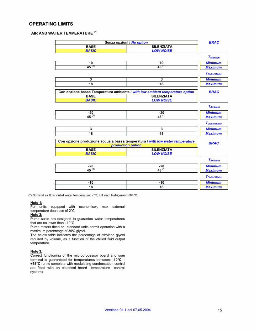
OPERATING LIMITS
AIR AND WATER TEMPERATURE (*)
BASE BASIC
Senza opzioni / No option BRAC SILENZIATA LOW NOISE
TAmbient
10 10 Minimum 45
(1) 43
(1) Maximum
TOutlet Water
3 3 Minimum 18 18 Maximum
Con opzione bassa Temperatura ambiente / with low ambient temperature option BRAC BASE BASIC
SILENZIATA LOW NOISE
TAmbient
-20 -20 Minimum 45
(1) 43
(1) Maximum
TOutlet Water
3 3 Minimum 18 18 Maximum
Con opzione produzione acqua a bassa temperatura / with low water temperature production option
BRAC BASE BASIC
SILENZIATA LOW NOISE
TAmbient
-20 -20 Minimum 45
(1) 43
(1) Maximum
TOutlet Water
-10 -10 Minimum 18 18 Maximum
(*) Nominal air flow; outlet water temperature: 7°C; full load; Refrigerant R407C.
Note 1: For units equipped with economiser, max external temperature decrease of 2°C Note 2: Pump seals are designed to guarantee water temperatures that are no lower than –10°C. Pump motors fitted on standard units permit operation with a maximum percentage of 30% glycol. The below table indicates the percentage of ethylene glycol required by volume, as a function of the chilled fluid output temperature.
Note 3: Correct functioning of the microprocessor board and user terminal is guaranteed for temperatures between: -10°C ÷+65°C (units complete with modulating condensation controlare fitted with an electrical board temperature control system).
Versione 01.1 del 07.05.2004 15
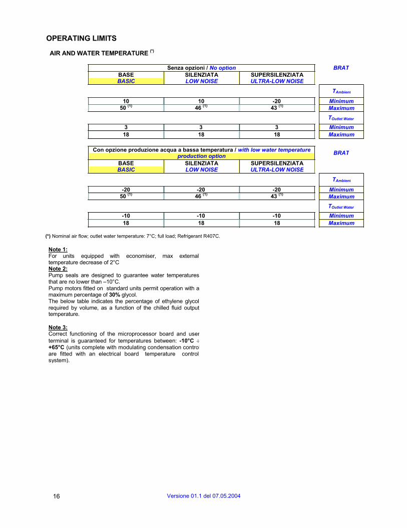
OPERATING LIMITS
AIR AND WATER TEMPERATURE (*)
Senza opzioni / No option BRAT BASE BASIC
SILENZIATA LOW NOISE
SUPERSILENZIATA ULTRA-LOW NOISE
TAmbient
10 10 -20 Minimum 50
(1) 46
(1) 43
(1) Maximum
TOutlet Water
3 3 3 Minimum 18 18 18 Maximum
Con opzione produzione acqua a bassa temperatura / with low water temperature production option
BRAT BASE BASIC
SILENZIATA LOW NOISE
SUPERSILENZIATA ULTRA-LOW NOISE
TAmbient
-20 -20 -20 Minimum 50
(1) 46
(1) 43
(1) Maximum
TOutlet Water
-10 -10 -10 Minimum 18 18 18 Maximum
(*) Nominal air flow; outlet water temperature: 7°C; full load; Refrigerant R407C.
Note 1: For units equipped with economiser, max external temperature decrease of 2°C Note 2: Pump seals are designed to guarantee water temperatures that are no lower than –10°C. Pump motors fitted on standard units permit operation with a maximum percentage of 30% glycol. The below table indicates the percentage of ethylene glycol required by volume, as a function of the chilled fluid output temperature.
Note 3: Correct functioning of the microprocessor board and user terminal is guaranteed for temperatures between: -10°C ÷+65°C (units complete with modulating condensation control are fitted with an electrical board temperature control system).
16 Versione 01.1 del 07.05.2004
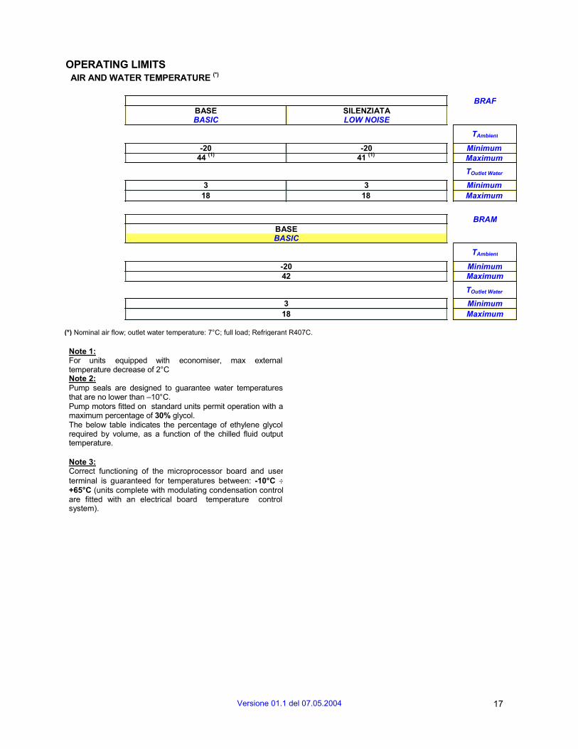
OPERATING LIMITS AIR AND WATER TEMPERATURE
(*)
BASE BASIC
SILENZIATA LOW NOISE
BRAF
TAmbient
-20 -20 Minimum 44
(1) 41
(1) Maximum
TOutlet Water
3 3 Minimum 18 18 Maximum
BASE BASIC
BRAM
TAmbient
-20 Minimum 42 Maximum
TOutlet Water
3 Minimum 18 Maximum
(*) Nominal air flow; outlet water temperature: 7°C; full load; Refrigerant R407C.
Note 1: For units equipped with economiser, max external temperature decrease of 2°C Note 2: Pump seals are designed to guarantee water temperatures that are no lower than –10°C. Pump motors fitted on standard units permit operation with a maximum percentage of 30% glycol. The below table indicates the percentage of ethylene glycol required by volume, as a function of the chilled fluid output temperature.
Note 3: Correct functioning of the microprocessor board and user terminal is guaranteed for temperatures between: -10°C ÷+65°C (units complete with modulating condensation control are fitted with an electrical board temperature control system).
Versione 01.1 del 07.05.2004 17

MAIN COMPONENTS
FRAMEWORK
The framework is made in galvanised steel sheet, with panels painted with epoxy powder paints (RAL 7037 colour) conforming to standard ASTM B117. Furthermore, all external screws, nuts, etc are in stainless steel.
ELECTRIC PANEL
The panel is built to conform to directive 73/23/EEC and to its relevant standards. The panel has a master door-locking disconnecting switch and is housed in an appropriate compartment protected by a panel fastened with ¼ turn screws.
The maximum internal temperature of the electrical panel is controlled by a thermostat, and is maintained within the parameters which ensure that the panel is protected by ventilation of external air.
Furthermore, versions supplied with modulating condensation control (units with the low ambient temperature option or free-cooling system), include a system for controlling minimum infernal temperature of the electrical panel by means of a self-adjusting anti-condensate electrical resistor.
Main features:
• phase sequence relay • in IP44 protection class; • 24 V auxiliary circuit for mainboard and fan contactors; • 230 V auxiliary circuit for compressor contactors; • phase monitor to ensure correct screw rotation (screw compressors) • phase monitor to ensure correct screw rotation (screw compressors) • every compressor is protected against overload and short-circuit by an automatic thermo-magnetic circuit
breaker (units equipped with scroll compressor) • fuses protect each compressor against short-circuits (for unis with screw compressor) • fans protected against overload and short circuit by an automatic thermo-magnetic circuit breaker; • pumps protected against overloading and short-circuits by motor overload cut-out. • contactors provided for compressors and pumps; • 2 voltage-free contacts for remote signalling of addressable alarms.
18 Versione 01.1 del 07.05.2004
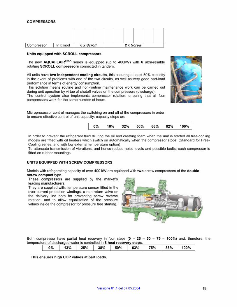
COMPRESSORS
Compressor nr x mod 6 x Scroll 2 x Screw
Units equipped with SCROLL compressors
The new AQUAFLAIRB.R.A series is equipped (up to 400kW) with 6 ultra-reliable rotating SCROLL compressors connected in tandem.
All units have two independent cooling circuits, this assuring at least 50% capacity in the event of problems with one of the two circuits, as well as very good part-load performance in terms of energy consumption. This solution means routine and non-routine maintenance work can be carried out during unit operation by virtue of shutoff valves on the compressors (discharge). The control system also implements compressor rotation, ensuring that all four compressors work for the same number of hours.
Microprocessor control manages the switching on and off of the compressors in order to ensure effective control of unit capacity; capacity steps are:
0% 16% 32% 50% 66% 82% 100%
In order to prevent the refrigerant fluid diluting the oil and creating foam when the unit is started all free-cooling models are fitted with oil heaters which switch on automatically when the compressor stops. (Standard for Free- Cooling series, and with low external temperature option) To attenuate transmission of vibrations, and hence reduce noise levels and possible faults, each compressor is fitted on rubber mountings.
UNITS EQUIPPED WITH SCREW COMPRESSORS
Models with refrigerating capacity of over 400 kW are equipped with two screw compressors of the double screw compact type. These compressors are supplied by the market's leading manufacturers. They are supplied with: temperature sensor fitted in the over-current protection windings, a non-return valve on the delivery line both for preventing screw reverse rotation, and to allow equalisation of the pressure values inside the compressor for pressure free starting.
Both compressor have partial heat recovery in four steps (0 – 25 – 50 – 75 – 100%) and, therefore, the temperature of discharged water is controlled in 8 heat recovery steps.
0% 13% 25% 38% 50% 63% 75% 88% 100%
This ensures high COP values at part loads.
Versione 01.1 del 07.05.2004 19
Furthermore, the compressor can be supplied with a slide valve with built-in economiser. This ensures greater liquid supercooling. In addition, thanks to the modulating inlet midway along the screw, one can improve the compressor process, by eliminating the low pressure at which the compressor normally operates. This ensures that COP is increased also at underpressure values, since the increase in yield is much higher than the increase in absorbed power.
Furthermore, on request, the units can be supplied with continuous modulation of refrigerating power to further improve COP. In this way, the refrigerator absorbs only the energy required by the system at any time, thus considerably cutting down electrical consumption.
To attenuate transmission of vibrations, and hence reduce noise levels and possible faults, each compressor is fitted on rubber mountings.
Ever an environment-conscious company, UNIFLAIR has designed these units for use with HFC-R407C, an environmentally friendly refrigerant, though they can also work with R22 or R134a - apply to UNIFLAIR ITALIA S.p.A. with your request.
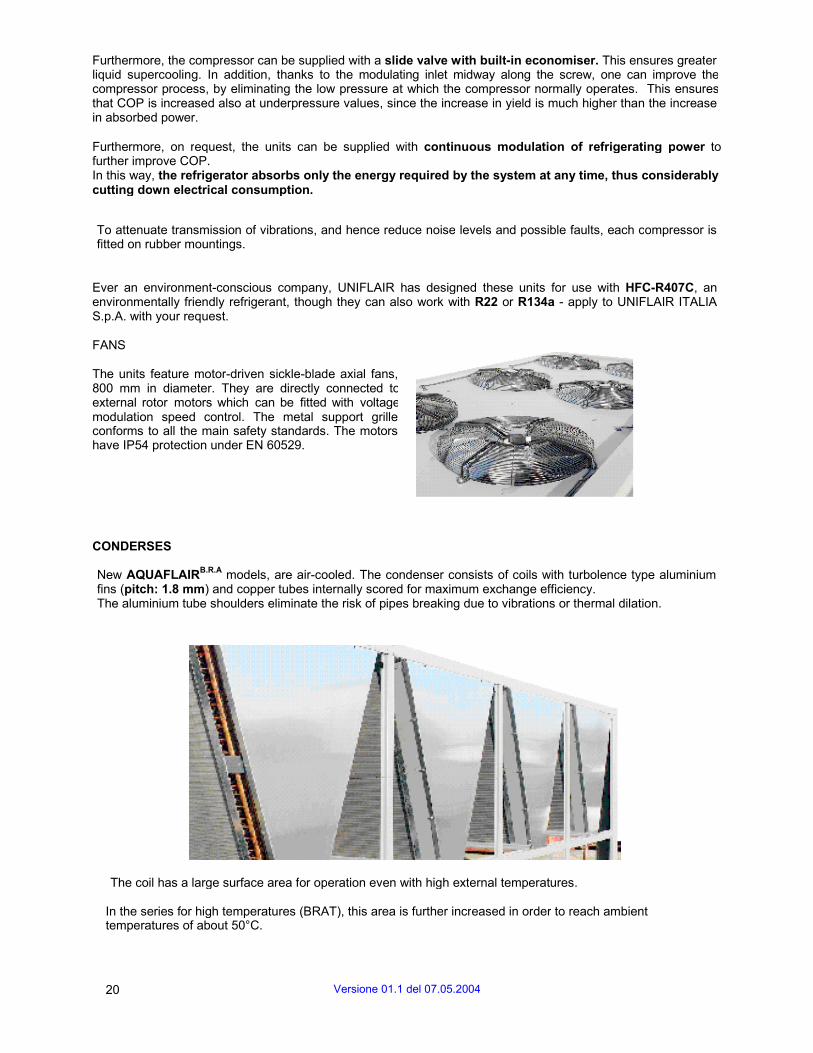
FANS
The units feature motor-driven sickle-blade axial fans, 800 mm in diameter. They are directly connected to external rotor motors which can be fitted with voltage modulation speed control. The metal support grille conforms to all the main safety standards. The motors have IP54 protection under EN 60529.
CONDERSES
New AQUAFLAIRB.R.A models, are air-cooled. The condenser consists of coils with turbolence type aluminium fins (pitch: 1.8 mm) and copper tubes internally scored for maximum exchange efficiency. The aluminium tube shoulders eliminate the risk of pipes breaking due to vibrations or thermal dilation.
The coil has a large surface area for operation even with high external temperatures.
In the series for high temperatures (BRAT), this area is further increased in order to reach ambient temperatures of about 50°C.
20 Versione 01.1 del 07.05.2004

If there are harsh conditions in the installation environment, various treatments are available for the exchanger: pre-painted aluminium, copper-copper protection and cataforesis aluminium treatment, which provides the best compromise between cost and performance (all on request).
EVAPORATOR
The shell & tube exchanger is removeable, has two cooling circuits and a single water circuit which operates with a very low pressure drop is builted with high-efficiency tubes, in order to guaranteed oil outflow.
It is completely covered in closed-cell expanded polyurethane to prevent the formation of condensation and reduce thermal dispersion.
Furthermore, this material is UV resistant.
ANTIVIBRATION FEET
To cut down vibrations, AQUAFLAIRB.R.A units can be supplied with antivibration supports.
Uniflair has selected spring supports for its units. They comprise five springs. These supports allow considerable yielding while being highly compact. As a result, they are particularly efficient in insulating low frequencies, typical of machines, such as refrigerators, running at low revs.
Moreover, the construction design permit to use in particularly difficult and/or aggressive places, as the supports are highly resistant to oils, corrosion and high temperatures.
Specifications: the springs are in C72 steel, and are epoxy painted; the bases are in elastomer with metal insert
HYDRONIC SECTION
The hydronic section of AQUAFLAIRB.R.A units is equipped with:
• Pump group: 1 or 1+1(stand-by); • Victaulic type connection to the user (only if pump group supplied); • Inlet interception valve (each for one pump) • Water flow pressure switch (standard) • Two interception valves on pump (inlet interception valve and non return valve on discharge, only
with pump group 1+1); • Exhaust on connection (standard with hydraulic kit); • Anti-freeze on (options):
-Evaporator; -Connection pipes; -Pump group.
Versione 01.1 del 07.05.2004 21
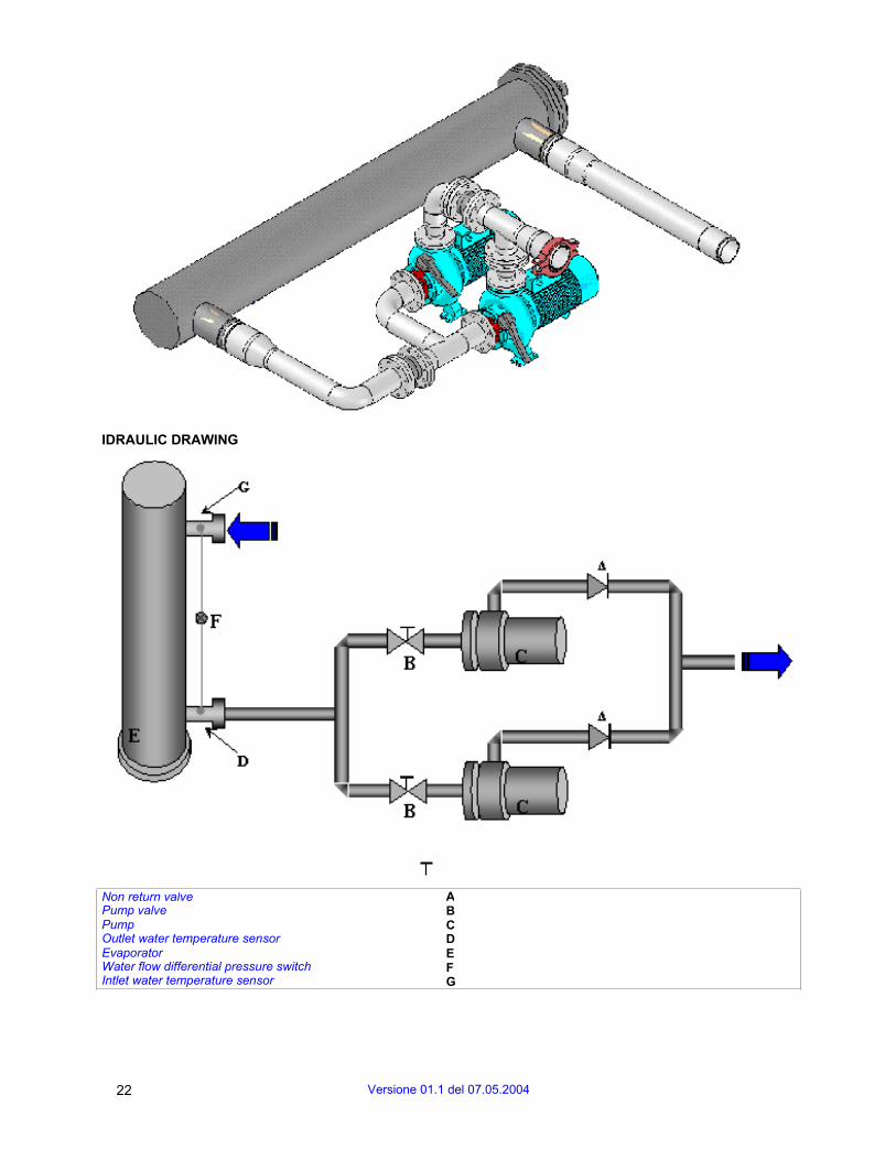
IDRAULIC DRAWING
Non return valve Pump valve Pump Outlet water temperature sensor Evaporator Water flow differential pressure switchIntlet water temperature sensor
A B C D E F G
22 Versione 01.1 del 07.05.2004
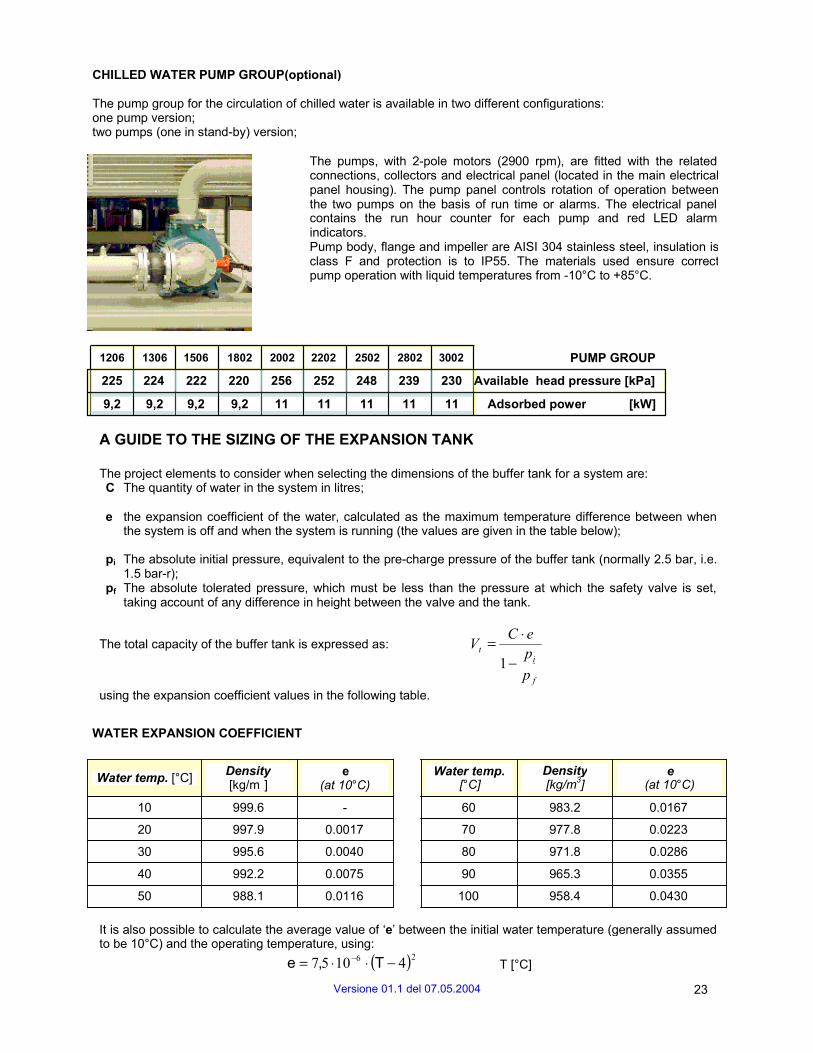
CHILLED WATER PUMP GROUP(optional)
The pump group for the circulation of chilled water is available in two different configurations: one pump version; two pumps (one in stand-by) version;
The pumps, with 2-pole motors (2900 rpm), are fitted with the related connections, collectors and electrical panel (located in the main electrical panel housing). The pump panel controls rotation of operation between the two pumps on the basis of run time or alarms. The electrical panel contains the run hour counter for each pump and red LED alarm indicators. Pump body, flange and impeller are AISI 304 stainless steel, insulation is class F and protection is to IP55. The materials used ensure correct pump operation with liquid temperatures from -10°C to +85°C.
1206 1306 1506 1802 2002 2202 2502 2802 3002 PUMP GROUP
225 224 222 220 256 252 248 239 230 Available head pressure [kPa]
9,2 9,2 9,2 9,2 11 11 11 11 11 Adsorbed power [kW]
A GUIDE TO THE SIZING OF THE EXPANSION TANK
The project elements to consider when selecting the dimensions of the buffer tank for a system are: C The quantity of water in the system in litres;
e the expansion coefficient of the water, calculated as the maximum temperature difference between when the system is off and when the system is running (the values are given in the table below);
pi The absolute initial pressure, equivalent to the pre-charge pressure of the buffer tank (normally 2.5 bar, i.e. 1.5 bar-r);
pf The absolute tolerated pressure, which must be less than the pressure at which the safety valve is set, taking account of any difference in height between the valve and the tank.
The total capacity of the buffer tank is expressed as: using the expansion coefficient values in the following table.
Vt = C ⋅ e
1 − pi
p f
WATER EXPANSION COEFFICIENT
Water temp. [°C] Density [kg/m ]
e (at 10°C)
Water temp. [°C]
Density [kg/m3]
e (at 10°C)
10 999.6 - 60 983.2 0.0167
20 997.9 0.0017 70 977.8 0.0223
30 995.6 0.0040 80 971.8 0.0286
40 992.2 0.0075 90 965.3 0.0355
50 988.1 0.0116 100 958.4 0.0430
It is also possible to calculate the average value of ‘e’ between the initial water temperature (generally assumed to be 10°C) and the operating temperature, using:
e = 7,5 ⋅10 −6 ⋅ (T − 4)2 T [°C]
Versione 01.1 del 07.05.2004 23

REACHING MAIN COMPONENTS
COMPRESSORS To reach the compressors (compartment in the base of the unit), remove the guards. With the guards removed, you have direct access to the compressors.
WARNING: HOT SURFACES, BURN HAZARD. With the guards removed, the compressors and the cooling circuit's delivery pipes are within reach. During the unit's regular operation, these parts get very hot and hence are potentially hazardous.
WARNING: When performing maintenance, ALWAYS set the master switch IG to ‘O’.
ELECTRICAL PANEL
To get inside the electrical panel, turn the handle of master switch IG to ’O’, turn the three latches a ¼ turn and lift using the grip. This procedure enables you to open the panel, hinged on the top of the electrical panel.
PUMP UNIT
To reach the pump unit (pumps are optional extras) or freecooling pump (in the base of the unit), remove the guards.
ATTENZIONE PRIMA DI QUALSIASI INTERVENTO LEGGERE ATTENTAMENTE IL LIBRETTO DI ISTRUZIONI.
APPARECCHIO IN TENSIONE E CON ORGANI ROTANTI: PRIMA DI INTERVENIRE SU QUALSIASI
PARTE ELETTRICA OPPURE SUL VENTILATORE/I TOGLIERE TENSIONE ALL’APPARECCHIO.
WARNING BEFORE ANY OPERATIONS ON THIS UNIT READ THE INSTRUCTION MANUAL CAREFULLY.
THIS EQUIPMENT CONTAINS COMPONENTS AT MAINS VOLTAGE AS WELL AS ROTATING FANS:
DISCONNECT POWER BEFORE ANY OPERATION ON ELECTRICAL COMPONENTS OR FANS.
ACTHUNG VOR ALLEN ARBEITEN AN DIESEM GERÄT IST DIE BEDIENUNGSANLEITUNG GENAU STUDIEREN.
DIESES GERÄT ENTHÄLT BUTEILE, DIE UNTER SPANNUNG STEHEN SOWIE SICH DREHENDE
VENTILATOREN: VOR ARBEITEN IM GERÄT IST DIE NETZZULEITUNG ABZUSCHALTEN.
ATTENTION LIRE ATTENTIVEMENT LE MANUEL D’INSTRUCTIONS AVANT TUOTE INTERVENTION.
CET EQUIPEMENT UTILISE DES COMPOSANTS ÉLECTRIQUE SOUS TENSION ET DES PIECES EN
MOUVEMENT. COUPER L'ALIMENTATION AU DISJONCTEUR AVANT TOOTE INTERVENTION SUR
LES COMPOSANTS ELECTRIQUES.
ATENCION ANTES DE CUALQUIER INTERVENCIÓN LEER ATENTAMENTE EL MANUAL DE INSTRUCCIONES.
APARATO BAJO TENSIÓN Y CON COMPONENTES ROTANTES. ANTES DE INTERVENIR SOBRE
CUALQUIER PARTE ELÈTRICA O SOBRE EL VENTILADOR/ES QUITAR TENSION AL APPARATO.
WARNING: Before removing the panel, you must set the master switch IG to ‘O’ to prevent the compressors and pumps, where fitted, reaching HIGH PRESSURE ALARM level.
24 Versione 01.1 del 07.05.2004
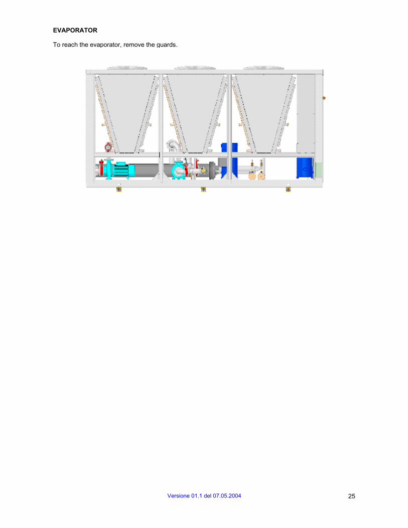
EVAPORATOR
To reach the evaporator, remove the guards.
Versione 01.1 del 07.05.2004 25
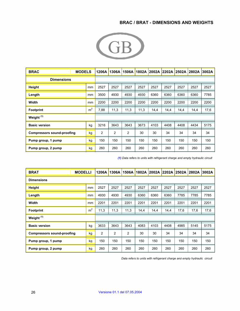
BRAC / BRAT - DIMENSIONS AND WEIGHTS
GB BRAC MODELS 1206A 1306A 1506A 1802A 2002A 2202A 2502A 2802A 3002A
Dimensions
Height mm 2527 2527 2527 2527 2527 2527 2527 2527 2527
Length mm 3500 4930 4930 4930 6360 6360 6360 6360 7785
Width mm 2200 2200 2200 2200 2200 2200 2200 2200 2200
Footprint m2 7,88 11,3 11,3 11,3 14,4 14,4 14,4 14,4 17,6
Weight (1)
Basic version kg 3216 3643 3643 3673 4103 4408 4408 4434 5175
Compressors sound-proofing kg 2 2 2 30 30 34 34 34 34
Pump group, 1 pump kg 150 150 150 150 150 150 150 150 150
Pump group, 2 pump kg 260 260 260 260 260 260 260 260 260
(1) Data refers to units with refrigerant charge and empty hydraulic circuit
BRAT MODELLI 1206A 1306A 1506A 1802A 2002A 2202A 2502A 2802A 3002A
Dimensions
Height mm 2527 2527 2527 2527 2527 2527 2527 2527 2527
Length mm 4930 4930 4930 6360 6360 6360 7785 7785 7785
Width mm 2201 2201 2201 2201 2201 2201 2201 2201 2201
Footprint m2 11,3 11,3 11,3 14,4 14,4 14,4 17,6 17,6 17,6
Weight (1)
Basic version kg 3633 3643 3643 4083 4103 4408 4985 5145 5175
Compressors sound-proofing kg 2 2 2 30 30 34 34 34 34
Pump group, 1 pump kg 150 150 150 150 150 150 150 150 150
Pump group, 2 pump kg 260 260 260 260 260 260 260 260 260
Data refers to units with refrigerant charge and empty hydraulic circuit
26 Versione 01.1 del 07.05.2004

BRAF / BRAM - DIMENSIONS AND WEIGHTS
GB BRAF MODELS 1206A 1306A 1506A 1802A 2002A 2202A 2502A 2802A 3002A
Dimensions
Height mm 2527 2527 2527 2527 2527 2527 2527 2527 2527
Length mm 3500 4930 4930 4930 6360 6360 6360 6360 7785
Width mm 2201 2201 2201 2201 2201 2201 2201 2201 2201
Footprint m2 7,88 11,3 11,3 11,3 14,4 14,4 14,4 14,4 17,6
Weight (1)
Basic version kg 3835 4514 4514 4544 5226 5531 5531 5557 6550
Compressors sound-proofing kg 2 2 2 30 30 34 34 34 34
Pump group, 1 pump kg 150 150 150 150 150 150 150 150 150
Pump group, 2 pump kg 260 260 260 260 260 260 260 260 260
(1) Data refers to units with refrigerant charge and empty hydraulic circuit
BRAM MODELLI 1206A 1306A 1506A 1802A 2002A 2202A 2502A 2802A 3002A
Dimensions
Height mm 2527 2527 2527 2527 2527 2527 2527 2527 2527
Length mm 4930 4930 4930 6360 6360 6360 7785 7785 7785
Width mm 2201 2201 2201 2201 2201 2201 2201 2201 2201
Footprint m2 11,3 11,3 11,3 14,4 14,4 14,4 17,6 17,6 17,6
Weight (1)
Basic version kg 4504 4514 4514 5206 5226 5531 6360 6520 6550
Pump group, 1 pump kg 150 150 150 150 150 150 150 150 150
Pump group, 2 pump kg 260 260 260 260 260 260 260 260 260
(1) Data refers to units with refrigerant charge and empty hydraulic circuit
Versione 01.1 del 07.05.2004 27

PARTIAL HEAT RECOVERY
Partial heat recovery is through two shell and tube exchangers fitted before the condensers. The below drawing indicates the partial heat recovery circuit fitted inside the unit, recommended circuit for user. In order to ensure the correct functioning of the chillers avoid that the heat recovery plate exchanger D is powered by water which is too cold (>35°C). For this reason use of a three way valve VMA is strongly advised yet remains the responsibility of the installer (see diagram).
VM
P
S VE VSAD
Circuito Acqua (non fornito da Uniflair) Water Circuit (not supplied by Uniflair)
VSC
VM Motorized 3-way valve
VSA Safety water tank
VE Expansion tank
P Circulation pump
S Water tank
CA Condensator finned coil
C Compressor
D partial heat recovery: heat plate exchanger
F Refrigerant circuit: shell&tube heat exchanger
VS Safety valve
CA
F
TOTAL HEAT RECOVERY
In the AQUAFLAIRB.R.A series, total heat recovery is achieved by means of two independent parallel circuits, each of which consists of a shell and tube heat exchanger. This option means heat that would otherwise be released outside by the condenser is used to produce hot water, typically for domestic use.
COOLING ONLY SERIES
In the cooling only series (BRAC end BRAT), total heat recovery is achieved based on two parallel circuits, each illustrated in the following diagram: if you wish to produce hot water, the three-way valve (B) diverts refrigerant through the recovery unit (E) - where condensation heat is released - instead of through the condenser (D). B
Legend:
A A. Compressor B. 4-way valve C. Evaporator D. Condenser E. Recovery exchanger F. Liquid receiver
ED C
F
28 Versione 01.1 del 07.05.2004
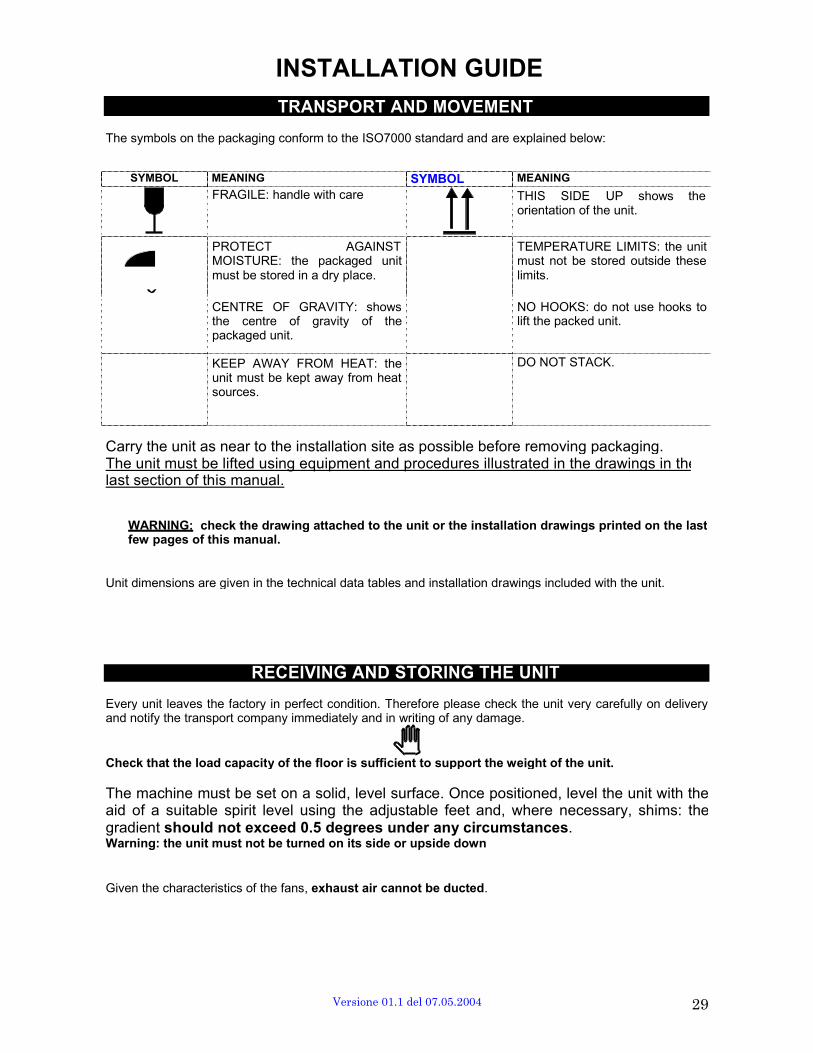
INSTALLATION GUIDE
TRANSPORT AND MOVEMENT
The symbols on the packaging conform to the ISO7000 standard and are explained below:
SYMBOL MEANING SYMBOL MEANING
FRAGILE: handle with care THIS SIDE UP shows the orientation of the unit.
PROTECT AGAINST MOISTURE: the packaged unit must be stored in a dry place.
TEMPERATURE LIMITS: the unit must not be stored outside these limits.
CENTRE OF GRAVITY: shows the centre of gravity of the packaged unit.
NO HOOKS: do not use hooks to lift the packed unit.
KEEP AWAY FROM HEAT: theunit must be kept away from heat sources.
DO NOT STACK.
Carry the unit as near to the installation site as possible before removing packaging. The unit must be lifted using equipment and procedures illustrated in the drawings in thelast section of this manual.
WARNING: check the drawing attached to the unit or the installation drawings printed on the last few pages of this manual.
Unit dimensions are given in the technical data tables and installation drawings included with the unit.
RECEIVING AND STORING THE UNIT
Every unit leaves the factory in perfect condition. Therefore please check the unit very carefully on delivery and notify the transport company immediately and in writing of any damage.
Check that the load capacity of the floor is sufficient to support the weight of the unit.
The machine must be set on a solid, level surface. Once positioned, level the unit with theaid of a suitable spirit level using the adjustable feet and, where necessary, shims: the gradient should not exceed 0.5 degrees under any circumstances. Warning: the unit must not be turned on its side or upside down
Given the characteristics of the fans, exhaust air cannot be ducted.
Versione 01.1 del 07.05.2004 29

POSITIONING THE CHILLER - CLEARANCES
This unit is designed and built for outdoor installation with free airflow to the condenser coils. The unit can be installed in a semi-closed position if the ventilation system is efficient enough to maintain temperatures below the values given in the section on Function Limits. The fan intake airflow through the condenser coils must not be obstructed in order not to compromise the efficiency of the unit and to prevent the unit being stopped by the safety devices. It is recommended that the unit is protected from rain, snow, water falling from gutters, etc. Do not install the unit near the sea (minimum recommended distance 200m) or near sulphur springs. If the installation location is particularly harsh, contact the Uniflair Sales dept. for possible technical solutions.
INSTALLATION TIPSCLEARANCES
The figure illustrates the minimum recommended distances for the unit to operate correctly, and for inside parts to be accessed easily for maintenance purposes.
0 mm 800 mm
2000 2000
UNIT LAYOUT The last section of the manual features diagrams for each unit, summarizing:
• Weight distribution • Plumbing and wiring • Overall dimensions
30 Versione 01.1 del 07.05.2004

HYDRAULIC CONNECTIONS (see also the enclosed installation drawings and hydraulic diagram)
For the hydraulic connection with welding to use the “cut short” of gallery supplied in equipment, otherwise to be connected directly with the pipages fluted to the joints Victaulic type of the unit having cure to embed adequately the packings of the joint.
1) CHECK that the section of the chilled water pipes and the power of the circulation pump fitted are sufficient. An inadequate water flow significantly reduces the cooling capacity of the unit.
2) CHECK the water intake/output directions. There are labels next to the intake, output and heat recovery connections as shown in the diagram below.
INGRESSO - INLET EINGANG - ENTREE
Iev ENTRADA
USCITA - OUTLET
AUSGANG - SORTIE
Uev SALIDA
3) CONNECT the chiller using flexible tubes to stop the transmission of vibrations. Fit shut-off valves so that the unit can be isolated from the water circuit;
4) INSULATE the chilled water pipes to stop the formation of condensation;
5) FIT temperature measuring points on the pipes near the intake and output connections;
6) INSTALL a metal filter in the section of pipe next to the unit intake to prevent pieces of welding or flakes of rust entering the heat exchanger.
7) PROVIDE a discharge well near the output connection in case the unit needs to be emptied.
MODELS BRAC 1206A 1306A 1506A 1802A 2002A 2202A 2502A 2802A 3002A
Hydraulic connections 4’’ 4’’ 4’’ 4’’ 5’’ 5’’ 5’’ 6’’ 6’’
MODELS BRAT 1206A 1306A 1506A 1802A 2002A 2202A 2502A 2802A 3002A
Hydraulic connections 4’’ 4’’ 4’’ 5’’ 5’’ 6’’ 6’’ 6’’ 6’’
MODELS BRAF 1206A 1306A 1506A 1802A 2002A 2202A 2502A 2802A 3002A
Hydraulic connections 4’’ 4’’ 4’’ 4’’ 5’’ 5’’ 5’’ 6’’ 6’’
MODELS BRAM 1206A 1306A 1506A 1802A 2002A 2202A 2502A 2802A 3002A
Hydraulic connections 4’’ 4’’ 4’’ 4’’ 5’’ 5’’ 5’’ 6’’ 6’’
Versione 01.1 del 07.05.2004 31
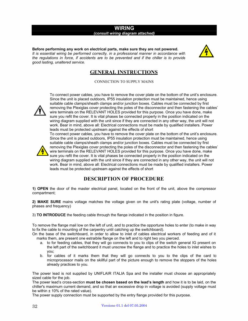
WIRING (consult wiring diagram attached)
Before performing any work on electrical parts, make sure they are not powered. It is essential wiring be performed correctly, in a professional manner in accordance with the regulations in force, if accidents are to be prevented and if the chiller is to provide good lasting, unaltered service.
GENERAL INSTRUCTIONS
CONNECTION TO SUPPLY MAINS
To connect power cables, you have to remove the cover plate on the bottom of the unit’s enclosure. Since the unit is placed outdoors, IP55 insulation protection must be maintained, hence using suitable cable clamps/sheath clamps and/or junction boxes. Cables must be connected by first removing the Plexiglas cover protecting the poles of the disconnector and then fastening the cables’ wire terminals on the RELEVANT HOLES provided for this purpose. Once you have done, make sure you refit the cover. It is vital phases be connected properly in the position indicated on the wiring diagram supplied with the unit since if they are connected in any other way, the unit will not work. Bear in mind, above all: Electrical connections must be made by qualified installers. Power leads must be protected upstream against the effects of short To connect power cables, you have to remove the cover plate on the bottom of the unit’s enclosure. Since the unit is placed outdoors, IP55 insulation protection must be maintained, hence using suitable cable clamps/sheath clamps and/or junction boxes. Cables must be connected by first removing the Plexiglas cover protecting the poles of the disconnector and then fastening the cables’ wire terminals on the RELEVANT HOLES provided for this purpose. Once you have done, make sure you refit the cover. It is vital phases be connected properly in the position indicated on the wiring diagram supplied with the unit since if they are connected in any other way, the unit will not work. Bear in mind, above all: Electrical connections must be made by qualified installers. Power leads must be protected upstream against the effects of short
DESCRIPTION OF PROCEDURE
1) OPEN the door of the master electrical panel, located on the front of the unit, above the compressor compartment;
2) MAKE SURE mains voltage matches the voltage given on the unit's rating plate (voltage, number of phases and frequency)
3) TO INTRODUCE the feeding cable through the flange indicated in the position in figure.
To remove the flange mail low on the left of unit, and to practice the opportune holes to enter (to make in way to fix the cable to mounting of the carpentry until catching up the switchboard). On the base of the switchboard, in order to allow to inlet of cables electrical workers of feeding and of it
marks them, are present one estraibile flange on the left and to right two you pierced. a. to for feeding cables, that they will go connects to you to clips of the switch general IG present on
the left part of the switchboard it must unscrew the flange and to practice the holes to inlet wishes to you;
b. for cables of it marks them that they will go connects to you to the clips of the card to microprocessor mails on the skillful part of the picture enough to remove the stoppers of the holes already practices to you.
The power lead is not supplied by UNIFLAIR ITALIA Spa and the installer must choose an appropriately sized cable for the job. The power lead’s cross-section must be chosen based on the lead’s length and how it is to be laid, on the chiller's maximum current demand, and so that an excessive drop in voltage is avoided (supply voltage must be within ± 10% of the rated value). The power supply connection must be supported by the entry flange provided for this purpose.
32 Versione 01.1 del 07.05.2004
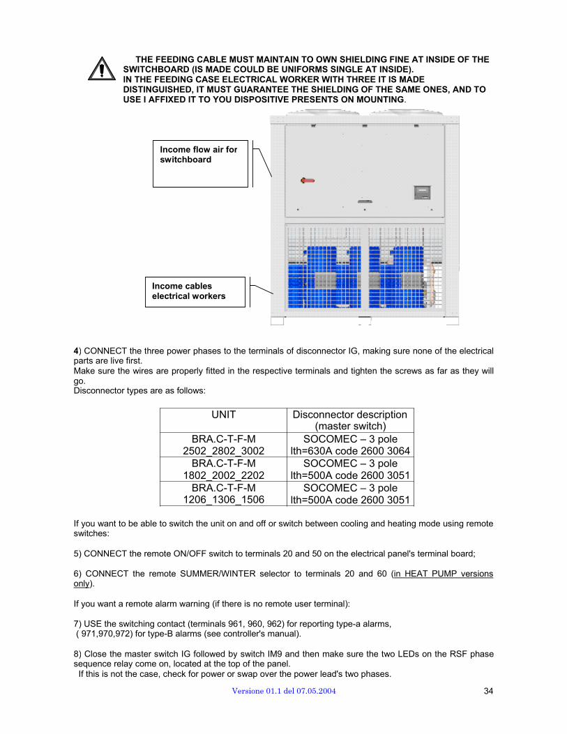
THE FEEDING CABLE MUST MAINTAIN TO OWN SHIELDING FINE AT INSIDE OF THE SWITCHBOARD (IS MADE COULD BE UNIFORMS SINGLE AT INSIDE). IN THE FEEDING CASE ELECTRICAL WORKER WITH THREE IT IS MADE DISTINGUISHED, IT MUST GUARANTEE THE SHIELDING OF THE SAME ONES, AND TO USE I AFFIXED IT TO YOU DISPOSITIVE PRESENTS ON MOUNTING.
Income flow air for switchboard
Income cables electrical workers
4) CONNECT the three power phases to the terminals of disconnector IG, making sure none of the electrical parts are live first. Make sure the wires are properly fitted in the respective terminals and tighten the screws as far as they will go. Disconnector types are as follows:
UNIT Disconnector description (master switch)
BRA.C-T-F-M 2502_2802_3002
BRA.C-T-F-M 1802_2002_2202
BRA.C-T-F-M 1206_1306_1506
SOCOMEC – 3 pole lth=630A code 2600 3064
SOCOMEC – 3 pole lth=500A code 2600 3051
SOCOMEC – 3 pole lth=500A code 2600 3051
If you want to be able to switch the unit on and off or switch between cooling and heating mode using remote switches:
5) CONNECT the remote ON/OFF switch to terminals 20 and 50 on the electrical panel's terminal board;
6) CONNECT the remote SUMMER/WINTER selector to terminals 20 and 60 (in HEAT PUMP versions only).
If you want a remote alarm warning (if there is no remote user terminal):
7) USE the switching contact (terminals 961, 960, 962) for reporting type-a alarms, ( 971,970,972) for type-B alarms (see controller's manual).
8) Close the master switch IG followed by switch IM9 and then make sure the two LEDs on the RSF phase sequence relay come on, located at the top of the panel. If this is not the case, check for power or swap over the power lead's two phases.
Versione 01.1 del 07.05.2004 34

FITTING THE OPTIONAL RS485 BOARD
1. Disconnect the power supply to the board; 2. Insert the RS485 card on the SERIAL
connector of the main board; 3. When making the connection of the serial line,
pay attention to polarities as shown; 4. The serial line must be closed by means of a
120Ω - 1/4W resistance, placed between the TX/RX+ and TX/RX- terminals of the board at the endline of the network.
The serial address is set via the user terminal using the relevant functions (see controller's manual).
Ingr. Chiave per la programm. PCO1
Ingressi analogici Ins. scheda seriale
35 Versione 01.1 del 07.05.2004

d switch-off, time-band program, switch-off
STARTUP AND TESTING CHECKLIST
BEFORE STARTING the unit, read the enclosed section on COMMISSIONING SCREW compressors, tobe found in the last section of this manual. Once installation is complete, follow the procedure illustrated. If you encounter problems, consult the'Problem Solving' section of the instruction manual or contact the Technical Servicing Dept.
1) CLOSE the electrical panel's master switch IG, MAKING SURE FIRST THAT THE POWER SUPPLY PHASES ARE PROPERLY CONNECTED;
2) OIL HEATING (on request in the versions 1206A – 1306A – 1506A , of series in the versions 1802A – 2002A – 2202A – 2502A – 2802A – 3002A) After to have given tension to the cooler to attend some hours before the starter they of the system to the aim ages to heat to sufficienza the oil of compressori (4-5 HOURS FOR UNIT WITH SCROLL COMPRESSORS , 1-2 FOR UNIT WITH TO SCREW COMPRESSORI). Do not switch off power during weekly breaks in operation. When left idle for longer periods, refrigerant may migrate into the compressor casings of its own accord. At startup, this may result in oil foaming, which is liable to lead to damage because of insufficient lubrication.
AT LEAST 12 HOURS AFTER switching on power, start the chiller proceeding as follows:
3) OPEN all water shutoff valves;
4) SWITCHING ON THE CONTROLLER (In units with mP20II controller only) When power is supplied to the auxiliary circuit of the chiller's electrical panel (IM9), the controller comes on as follows:
- the yellow power ON LED on the master board lights (see MASTER BOARD LAYOUT); - a short audible signal is heard; - the display shows the start screen for 10 seconds before switching to unit stopped status; When the unit is powered but not running, 3 fields are active on the user terminal display: - Time and current date (only in units featuring a clock card); - Return water temperature and (only in units featuring free cooling) external temperature; - One of the following messages indicating what has switched the unit off: ON/OFF button, supervisor system, time with manual override.
TMP. ACQUA IN . . . . . °C
TMP. ACQUA OUT . . . . . °C
UNITÁ OFF
START the unit (READ THE SECTION ON COMMISSIONING SCREW
COMPRESSORS FIRST) by pressing the key on the user terminal.
MAKE SURE none of the red alarm LEDs light: if a LED lights, refer to the ‘Problem solving guide' section and instructions given in the Controller's manual. To switch off the unit, use the local terminal's controls to enable the pump to stop at least 10 seconds after the chiller, thus preventing the chiller from stopping in no- flow conditions.
Versione 01.1 del 07.05.2004 35
PROGRAMMING AND REGULATION This system can be programmed according to the specific needs of its user, normally employed in technological applications, its features enables an independent control of all compressors on/off switches. The regulation program, found in the FLASH EPROM memory (base card), is identified by an alphanumeric code – its logic is explained here below.
Control parameters (set points, alarms) and display of data and events (reading of set points and control values, operating events or/and alarms) are all programmed through the User terminal as shown below
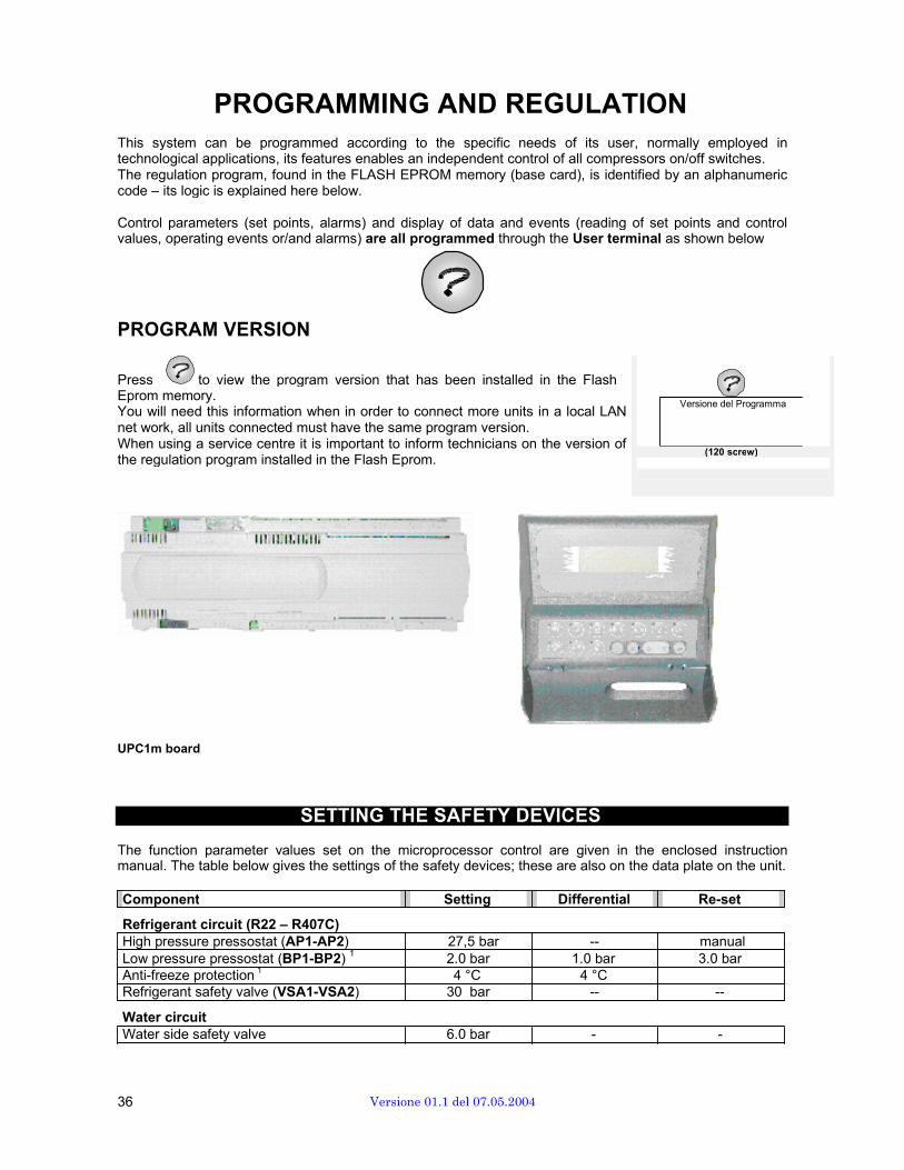
PROGRAM VERSION
Press to view the program version that has been installed in the Flash Eprom memory. You will need this information when in order to connect more units in a local LAN net work, all units connected must have the same program version. When using a service centre it is important to inform technicians on the version of the regulation program installed in the Flash Eprom.
Versione del Programma
(120 screw)
UPC1m board
SETTING THE SAFETY DEVICES
The function parameter values set on the microprocessor control are given in the enclosed instruction manual. The table below gives the settings of the safety devices; these are also on the data plate on the unit.
Component Setting Differential Re-set
Refrigerant circuit (R22 – R407C) High pressure pressostat (AP1-AP2) 27,5 bar -- manual Low pressure pressostat (BP1-BP2) 1 2.0 bar 1.0 bar 3.0 bar Anti-freeze protection 1 4 °C 4 °C Refrigerant safety valve (VSA1-VSA2) 30 bar -- --
Water circuit Water side safety valve 6.0 bar - -
36 Versione 01.1 del 07.05.2004
MICROPROCESSOR CONTROL SYSTEM
Control system consists of two sections:
• two microprocessor control board (UPC1m), fitted in the unit • a user interface which can be either local or remote.
Control system uses sophisticated algorithms in order to control outlet water temperature between minimal gap and to monitor and protect all unit components. User interface provides clear information on unit status and any current alarms.
UPC1m ADVANCED CONTROL CARD
This new advanced control is designed to be flexibly used for both comfort and technological applications enabling:
• independent control of all compressors (units equipped with Scroll compressors) • operation (switch-on/off) of all compressors in units featuring Scroll compressors to be controlled
independently • management of cooling steps (8) or continuous control on screw compressors (optional extra).
Control system regulation program resides in the FLASH-EPROM on the base circuit. The programming of the control parameters (set points, differentials, alarm thresholds) and the displaying of data and events (set point readings, monitored values, function events and alarms) are done using the optional User Terminal (mP20II) shown in the diagram below.
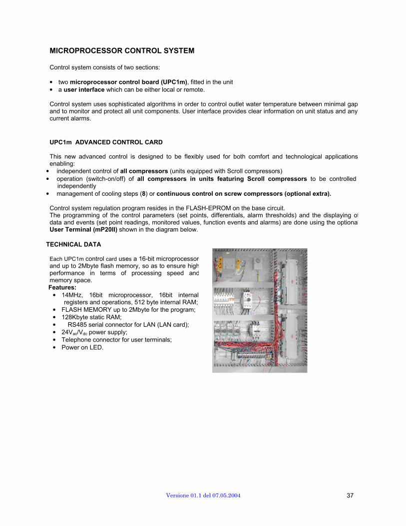
TECHNICAL DATA
Each UPC1m control card uses a 16-bit microprocessor and up to 2Mbyte flash memory, so as to ensure high performance in terms of processing speed and memory space. Features:
• 14MHz, 16bit microprocessor, 16bit internal registers and operations, 512 byte internal RAM;
• FLASH MEMORY up to 2Mbyte for the program; • 128Kbyte static RAM; • RS485 serial connector for LAN (LAN card); • 24Vac/Vdc power supply; • Telephone connector for user terminals; • Power on LED.
Versione 01.1 del 07.05.2004 37

MAIN FUNCTIONS
Main functions of the microprocessor control are: • Outlet water temperature regulation; • Modulating condensation control (1); • Set-point changing by external sensor 0-10 V (with
adaptor); • Double set-point with contact selector (2); • Set-point compensation with external temperature (2); • Automatic adjustment of delta set-point • Remote user terminal; • Total heat recovery management; • Partial heat recovery management; • High / low pressure transducer; • Refrigerant charge monitoring). • LAN card (standard); • Clock card (standard); • RS485 serial adaptor; • BMS compatibility; • Interconnected management (up to 10) and group
management (up to 10, with one or two units in stand- by).
Note: (1) only in versions including this kind control: units with low external temperature option or units with free-
cooling system (2) settable; (3) only witht E.E.V.
Anti-freeze features: • Management of anti-freeze heaters; • Anti-freeze evaporator function management (with pressure sensors); • Anti-freeze function during stand-by on pumps.
Alarm management: • Historical alarm events (with date and time in presence of clock card); • General alarm contact (addresses); • Addresses alarm contact (2).
Compressors / pumps monitoring: • Compressors rotation (FIFO logic); • Compressor hours run; • Programmed maintenance threshold signalling; • Compressor on/off counter; • Two pumps management (run + stand-by) with rotation; • Pump hours run (including free-cooling pump).
38 Versione 01.1 del 07.05.2004
FAN SPEED CONTROL
One of the most important and innovative features characterizing the control system of the new AQUAFLAIRB.R.A. series is fan speed control. Depending on the version / options, there are three types of control available:
BRAC • basic version
Continuous speed control of one bank of fans up to 880 rpm; ON-OFF control on other bank (maximum speed:880 rpm)
• standard version with low ambient temperature option Continuous speed control of fans belonging to both banks up to 880 rpm;
• low-noise version Continuous speed control of one bank of fans up to 660 rpm; ON-OFF control on other bank (maximum speed: rpm)
• low-noise version with low ambient temperature option Continuous speed control of fans belonging to both banks up to 880 rpm
BRAT • basic version
Continuous speed control of one bank of fans up to 880 rpm; ON-OFF control on other bank (maximum speed:880 rpm)
• low-noise version Continuous speed control of one bank of fans up to 660 rpm; ON-OFF control on other bank (maximum speed: 660 rpm)
• ultra-low-noise version with low ambient temperature option Continuous speed control of fans belonging to both banks up to 550 rpm;
BRAF • basic
Continuous speed control of fans belonging to both banks up to 880 rpm; • low-noise
Continuous speed control of fans belonging to both banks up to 660 rpm;
BRAM • basic
Continuous speed control of fans belonging to both banks up to 550 rpm.
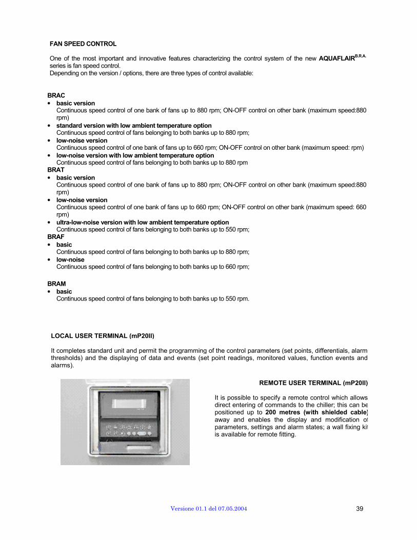
LOCAL USER TERMINAL (mP20II)
It completes standard unit and permit the programming of the control parameters (set points, differentials, alarm thresholds) and the displaying of data and events (set point readings, monitored values, function events and alarms).
REMOTE USER TERMINAL (mP20II)
It is possible to specify a remote control which allows direct entering of commands to the chiller; this can be positioned up to 200 metres (with shielded cable) away and enables the display and modification of parameters, settings and alarm states; a wall fixing kit is available for remote fitting.
Versione 01.1 del 07.05.2004 39
LOCAL NETWORK CONNECTION AQUAFLAIR
B.R.A. units can be interconnected with each other to form a local area network, thus giving the range an additional degree of flexibility. There are two kinds of connection: Interconnected management of n chillers (up to 10) and Management of a group of chillers (up to 10, with one or two backups units). With interconnected management, you can connect two control cards with each other and use a single user terminal to manage the units as though they were a single device, sharing settings, general compressor rotation, and overall trouble management. By managing the compressors, up to 12/16 cooling steps can be achieved, thus optimising energy consumption. Rotation, in particular, is based on FIFO logic: each time, the compressor that has been off for longest is switched on first, meaning hours of operation are distributed evenly to achieve uniform ageing. If more than two chillers (possibly to manage one or two standby units) and up to ten units at most (with one or two backup units) are connected on the same hydraulic system, group management can be used by connecting all the cards together and using a single user terminal to manage units as though they were a single device, sharing settings, general compressor rotation, overall trouble management etc.
The local network uses high-speed RS485 communication (64 kByte/s) with 2-core shielded telephone cable.
SUPERVISION SYSTEMS CONNECTION
AQUAFLAIRB.R.A. range chillers are conceived and designed to be installed in a LAN managed by supervision
systems. Hence they are compatible with the more common external BMS protocols. i.e.:
EXTERNAL BMS COMPATIBILITY
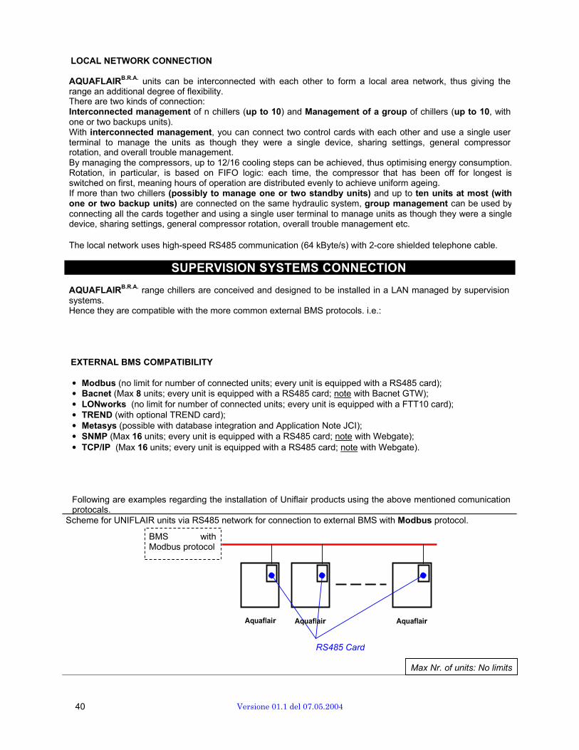
• Modbus (no limit for number of connected units; every unit is equipped with a RS485 card); • Bacnet (Max 8 units; every unit is equipped with a RS485 card; note with Bacnet GTW); • LONworks (no limit for number of connected units; every unit is equipped with a FTT10 card); • TREND (with optional TREND card); • Metasys (possible with database integration and Application Note JCI); • SNMP (Max 16 units; every unit is equipped with a RS485 card; note with Webgate); • TCP/IP (Max 16 units; every unit is equipped with a RS485 card; note with Webgate).
Following are examples regarding the installation of Uniflair products using the above mentioned comunication protocals. Scheme for UNIFLAIR units via RS485 network for connection to external BMS with Modbus protocol.
BMS with Modbus protocol
Aquaflair Aquaflair Aquaflair
RS485 Card
Max Nr. of units: No limits
40 Versione 01.1 del 07.05.2004
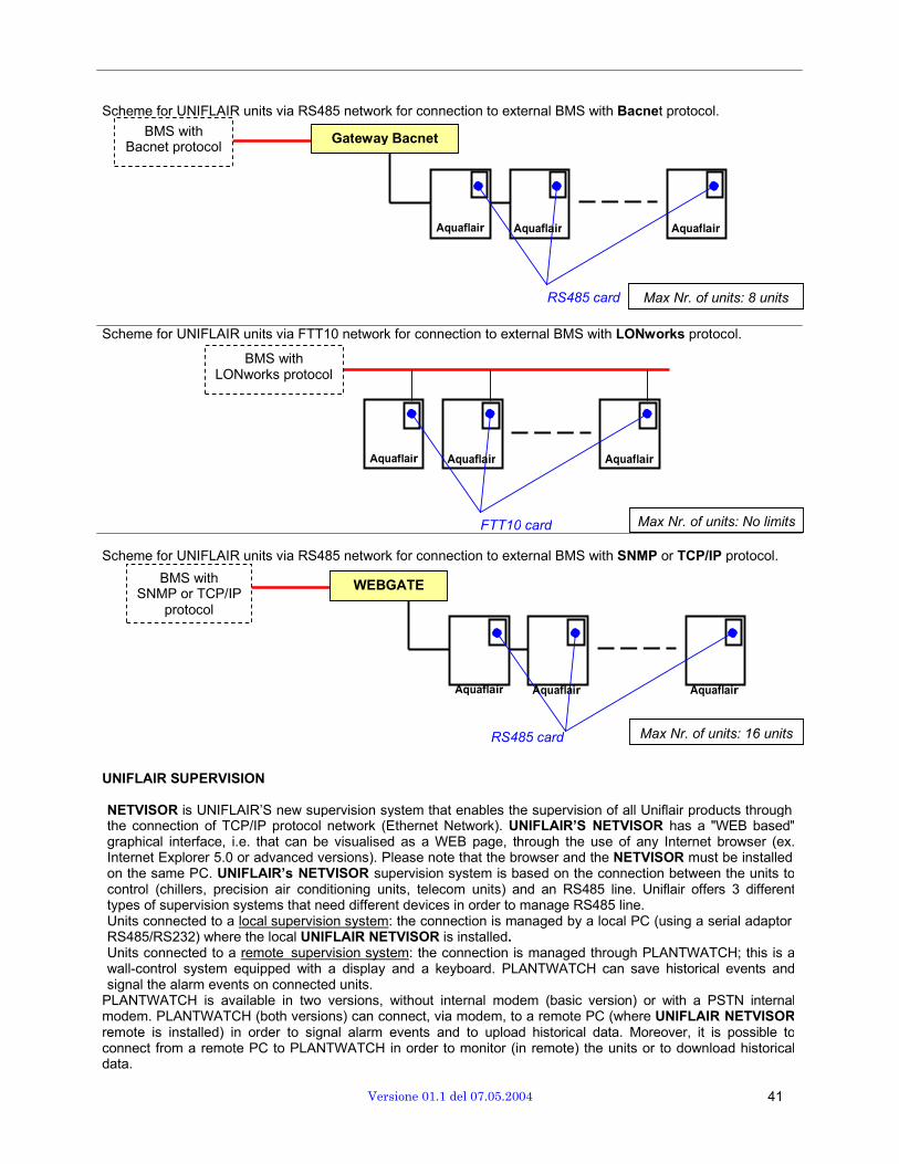
Scheme for UNIFLAIR units via RS485 network for connection to external BMS with Bacnet protocol.
BMS with Bacnet protocol
Gateway Bacnet
Aquaflair Aquaflair Aquaflair
RS485 card Max Nr. of units: 8 units
Scheme for UNIFLAIR units via FTT10 network for connection to external BMS with LONworks protocol.
BMS with LONworks protocol
Aquaflair Aquaflair Aquaflair
FTT10 card Max Nr. of units: No limits
Scheme for UNIFLAIR units via RS485 network for connection to external BMS with SNMP or TCP/IP protocol.
BMS with SNMP or TCP/IP
protocol
WEBGATE
Aquaflair Aquaflair Aquaflair
RS485 card Max Nr. of units: 16 units
UNIFLAIR SUPERVISION
NETVISOR is UNIFLAIR’S new supervision system that enables the supervision of all Uniflair products through the connection of TCP/IP protocol network (Ethernet Network). UNIFLAIR’S NETVISOR has a "WEB based" graphical interface, i.e. that can be visualised as a WEB page, through the use of any Internet browser (ex. Internet Explorer 5.0 or advanced versions). Please note that the browser and the NETVISOR must be installed on the same PC. UNIFLAIR’s NETVISOR supervision system is based on the connection between the units to control (chillers, precision air conditioning units, telecom units) and an RS485 line. Uniflair offers 3 different types of supervision systems that need different devices in order to manage RS485 line. Units connected to a local supervision system: the connection is managed by a local PC (using a serial adaptor RS485/RS232) where the local UNIFLAIR NETVISOR is installed. Units connected to a remote supervision system: the connection is managed through PLANTWATCH; this is a wall-control system equipped with a display and a keyboard. PLANTWATCH can save historical events and signal the alarm events on connected units.
PLANTWATCH is available in two versions, without internal modem (basic version) or with a PSTN internal modem. PLANTWATCH (both versions) can connect, via modem, to a remote PC (where UNIFLAIR NETVISOR remote is installed) in order to signal alarm events and to upload historical data. Moreover, it is possible to connect from a remote PC to PLANTWATCH in order to monitor (in remote) the units or to download historical data.
Versione 01.1 del 07.05.2004 41
Uniflair also supplies a remote monitoring configuration; this solution combines the advantages of local and remote supervision: local PC manages RS485 line (using NETVISOR local) and it can connect to a remote PC (equipped with NETVISOR remote).
NETVISOR manages analogic PTSN modem and GSM modem for sending FAXES or SMS. Moreover, NETVISOR can be used as a WEB server, i.e. via PC’s connected with Ethernet networks using an Internet browser in order to download WEB pages that visualise unit data. This operation is also possible through the use of WEBGATE that manages RS485 line and is connected with Ethernet networks as WEB server (with a specific IP address). Local or remote PC (not supplied by Uniflair) requirements: microprocessor Pentium III, 64Mb RAM, USB adaptor and serial adaptor (COM) free, O.S. Windows 98, NT, 2000, XP.
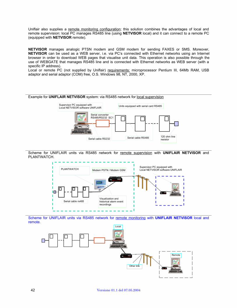
Example for UNIFLAIR NETVISOR system: via RS485 network for local supervision
Supervisor PC equipped with Local NETVISOR software UNIFLAIR
Units equipped with serial card RS485
Serial converter RS485/RS232 SC1
Serial cable RS232 Serial cable RS485 120 ohm line resistor
Scheme for UNIFLAIR units via RS485 network for remote supervision with UNIFLAIR NETVISOR and PLANTWATCH.
PLANTWATCH Modem PSTN / Modem GSM Supervisor PC equipped with Local NETVISOR software UNIFLAIR
Serial cable rs485 Visualization and historical alarm event recordings
Scheme for UNIFLAIR units via RS485 network for remote monitoring with UNIFLAIR NETVISOR local and remote.
Local
Remote
Other line
42 Versione 01.1 del 07.05.2004
FREE-COOLING SERIES
When the chiller is used for the cooling of technological systems which operate in all seasons, new BRAF and BRAM chillers series have free-cooling function that can significantly reduce energy consumption.
In chillers belonging to said series, free-cooling system is implemented. Using this system, when external temperature is sufficiently low, there is no need to use the “cooling” part of the chiller, namely the compressors, which are the components responsible for most energy consumption. In these units, chilled water is actually produced using external air, meaning the only energy required is that demanded by the fans.
With this method, chilled water can be provided at no cost.
AQUAFLAIRB.R.A. units, like all other Uniflair products, give you the option of using free cooling even when
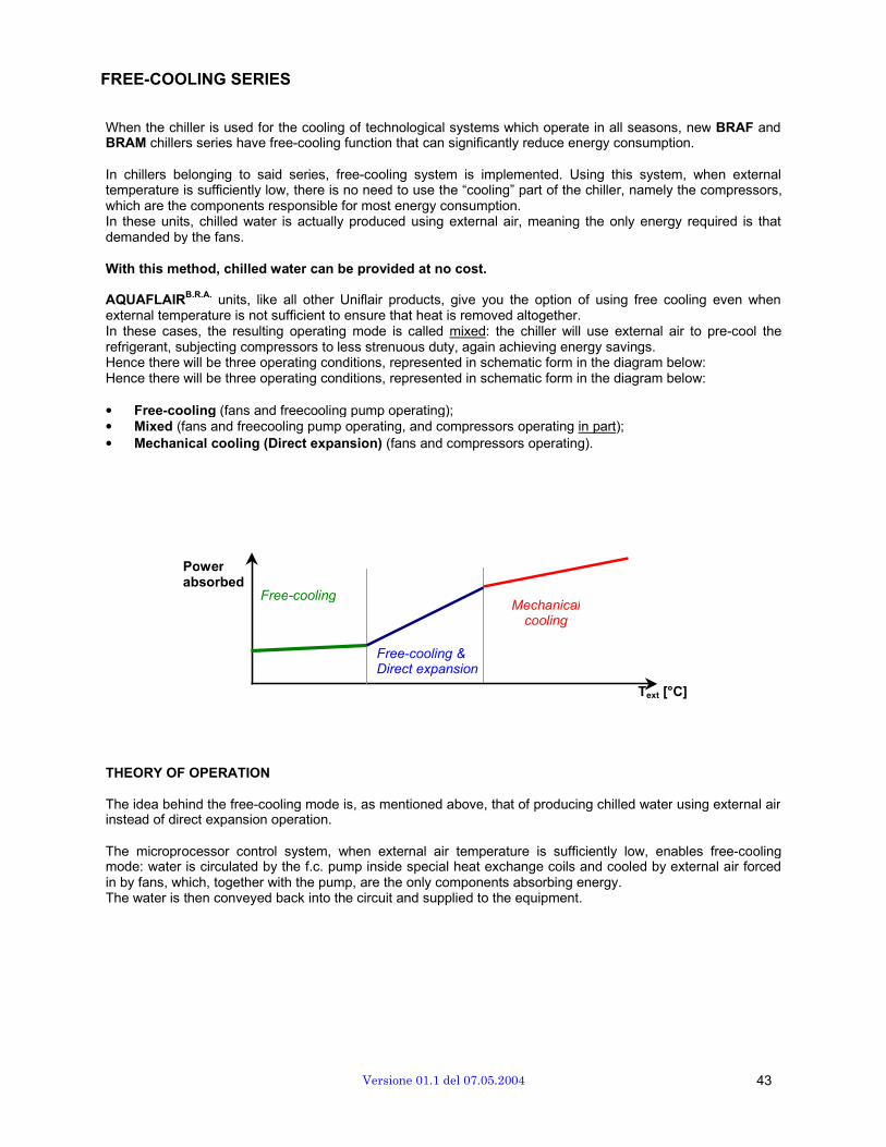
external temperature is not sufficient to ensure that heat is removed altogether. In these cases, the resulting operating mode is called mixed: the chiller will use external air to pre-cool the refrigerant, subjecting compressors to less strenuous duty, again achieving energy savings. Hence there will be three operating conditions, represented in schematic form in the diagram below: Hence there will be three operating conditions, represented in schematic form in the diagram below:
• Free-cooling (fans and freecooling pump operating); • Mixed (fans and freecooling pump operating, and compressors operating in part); • Mechanical cooling (Direct expansion) (fans and compressors operating).
Power absorbed
Free-cooling Mechanical
cooling
Free-cooling & Direct expansion
Text [°C]
THEORY OF OPERATION
The idea behind the free-cooling mode is, as mentioned above, that of producing chilled water using external air instead of direct expansion operation.
The microprocessor control system, when external air temperature is sufficiently low, enables free-cooling mode: water is circulated by the f.c. pump inside special heat exchange coils and cooled by external air forced in by fans, which, together with the pump, are the only components absorbing energy. The water is then conveyed back into the circuit and supplied to the equipment.
Versione 01.1 del 07.05.2004 43
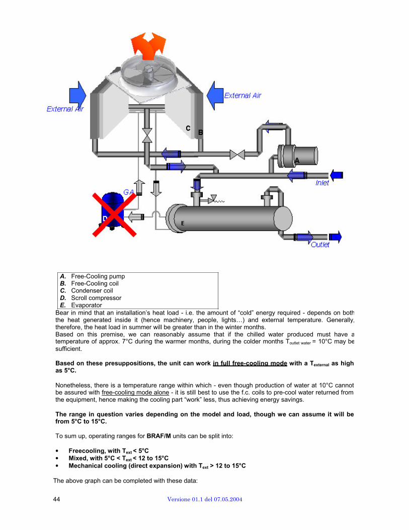
A. Free-Cooling pump B. Free-Cooling coil C. Condenser coil D. Scroll compressor E. Evaporator
Bear in mind that an installation’s heat load - i.e. the amount of “cold” energy required - depends on both the heat generated inside it (hence machinery, people, lights…) and external temperature. Generally, therefore, the heat load in summer will be greater than in the winter months. Based on this premise, we can reasonably assume that if the chilled water produced must have a temperature of approx. 7°C during the warmer months, during the colder months Toutlet water = 10°C may be sufficient.
Based on these presuppositions, the unit can work in full free-cooling mode with a Texternal as high as 5°C.
Nonetheless, there is a temperature range within which - even though production of water at 10°C cannot be assured with free-cooling mode alone - it is still best to use the f.c. coils to pre-cool water returned from the equipment, hence making the cooling part “work” less, thus achieving energy savings.
The range in question varies depending on the model and load, though we can assume it will be from 5°C to 15°C.
To sum up, operating ranges for BRAF/M units can be split into:
• Freecooling, with Text < 5°C • Mixed, with 5°C < Text < 12 to 15°C • Mechanical cooling (direct expansion) with Text > 12 to 15°C
The above graph can be completed with these data:
44 Versione 01.1 del 07.05.2004
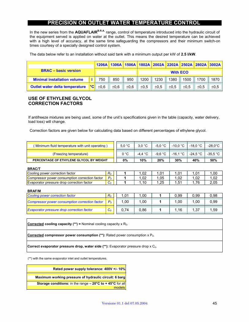
PRECISION ON OUTLET WATER TEMPERATURE CONTROL
In the new series from the AQUAFLAIRB.R.A. range, control of temperature introduced into the hydraulic circuit of the equipment served is applied on water at the outlet. This means the desired temperature can be achieved with a high level of accuracy, at the same time safeguarding the compressors and their minimum switch-on times courtesy of a specially designed control system.
The data below refer to an installation without said tank with a minimum output per kW of 2.5 l/kW.
1206A 1306A 1506A 1802A 2002A 2202A 2502A 2802A 3002A
BRAC – basic version With ECO
Minimal installation volume l 750 850 950 1200 1230 1380 1500 1700 1870
Outlet water delta temperature °C ±0,6 ±0,6 ±0,6 ±0,5 ±0,5 ±0,5 ±0,5 ±0,5 ±0,5
USE OF ETHYLENE GLYCOLCORRECTION FACTORS
If antifreeze mixtures are being used, some of the unit’s specifications given in the table (capacity, water delivery, load loss) will change.
Correction factors are given below for calculating data based on different percentages of ethylene glycol.
( Minimum fluid temperature with unit operating ) 5,0 °C 3,0 °C -5,0 °C -10,0 °C -18,0 °C -28,0°C
(Freezing temperature) 0 °C -4,4 °C -9,6 °C -16,1 °C -24,5 °C -35,5 °C
PERCENTAGE OF ETHYLENE GLYCOL BY WEIGHT 0% 10% 20% 30% 40% 50%
BRAC/T Cooling power correction factor R0 1 1,02 1,01 1,01 1,01 1,00 Compressor power consumption correction factor P0 1 1,02 1,05 1,02 1,02 1,02 Evaporator pressure drop correction factor C0 1 1,10 1,25 1,51 1,76 2,05
BRAF/M Cooling power correction factor R0 1,01 1,00 1 0,99 0,99 0,98
Compressor power consumption correction factor P0 1,00 1,00 1 1,00 1,00 0,99
Evaporator pressure drop correction factor C0 0,74 0,86 1 1,16 1,37 1,59
Corrected cooling capacity (**) = Nominal cooling capacity x R0.
Corrected compressor power consumption (**): Rated power consumption x P0.
Correct evaporator pressure drop, water side (**): Evaporator pressure drop x Co.
(**) with the same evaporator inlet and outlet temperatures.
Rated power supply tolerance: 400V +/- 10%
Maximum working pressure of hydraulic circuit: 6 barg
Storage conditions: in the range – 20°C to + 45°C for all models
Versione 01.1 del 07.05.2004 45
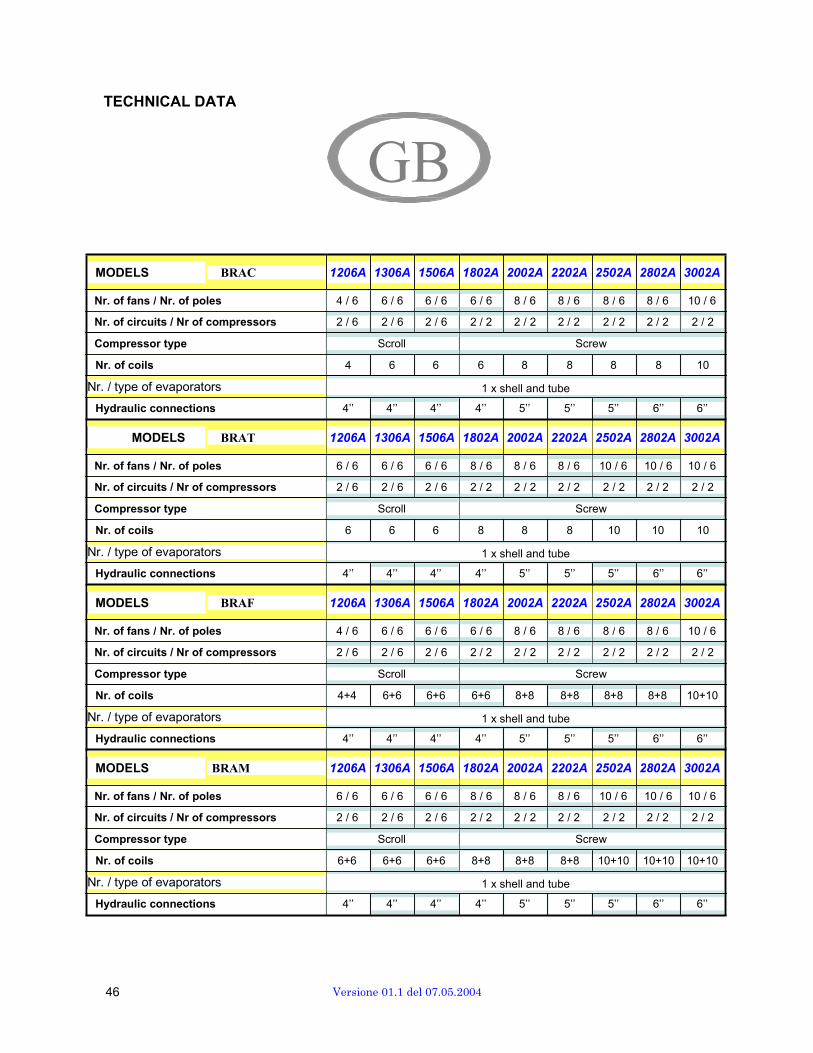
TECHNICAL DATA
GB
MODELS BRAC 1206A 1306A 1506A 1802A 2002A 2202A 2502A 2802A 3002A
Nr. of fans / Nr. of poles 4 / 6 6 / 6 6 / 6 6 / 6 8 / 6 8 / 6 8 / 6 8 / 6 10 / 6
Nr. of circuits / Nr of compressors 2 / 6 2 / 6 2 / 6 2 / 2 2 / 2 2 / 2 2 / 2 2 / 2 2 / 2
Compressor type Scroll Screw
Nr. of coils 4 6 6 6 8 8 8 8 10
Nr. / type of evaporators 1 x shell and tube
Hydraulic connections 4’’ 4’’ 4’’ 4’’ 5’’ 5’’ 5’’ 6’’ 6’’
MODELS BRAT 1206A 1306A 1506A 1802A 2002A 2202A 2502A 2802A 3002A
Nr. of fans / Nr. of poles 6 / 6 6 / 6 6 / 6 8 / 6 8 / 6 8 / 6 10 / 6 10 / 6 10 / 6
Nr. of circuits / Nr of compressors 2 / 6 2 / 6 2 / 6 2 / 2 2 / 2 2 / 2 2 / 2 2 / 2 2 / 2
Compressor type Scroll Screw
Nr. of coils 6 6 6 8 8 8 10 10 10
Nr. / type of evaporators 1 x shell and tube
Hydraulic connections 4’’ 4’’ 4’’ 4’’ 5’’ 5’’ 5’’ 6’’ 6’’
MODELS BRAF 1206A 1306A 1506A 1802A 2002A 2202A 2502A 2802A 3002A
Nr. of fans / Nr. of poles 4 / 6 6 / 6 6 / 6 6 / 6 8 / 6 8 / 6 8 / 6 8 / 6 10 / 6
Nr. of circuits / Nr of compressors 2 / 6 2 / 6 2 / 6 2 / 2 2 / 2 2 / 2 2 / 2 2 / 2 2 / 2
Compressor type Scroll Screw
Nr. of coils 4+4 6+6 6+6 6+6 8+8 8+8 8+8 8+8 10+10
Nr. / type of evaporators 1 x shell and tube
Hydraulic connections 4’’ 4’’ 4’’ 4’’ 5’’ 5’’ 5’’ 6’’ 6’’
MODELS BRAM 1206A 1306A 1506A 1802A 2002A 2202A 2502A 2802A 3002A
Nr. of fans / Nr. of poles 6 / 6 6 / 6 6 / 6 8 / 6 8 / 6 8 / 6 10 / 6 10 / 6 10 / 6
Nr. of circuits / Nr of compressors 2 / 6 2 / 6 2 / 6 2 / 2 2 / 2 2 / 2 2 / 2 2 / 2 2 / 2
Compressor type Scroll Screw
Nr. of coils 6+6 6+6 6+6 8+8 8+8 8+8 10+10 10+10 10+10
Nr. / type of evaporators 1 x shell and tube
Hydraulic connections 4’’ 4’’ 4’’ 4’’ 5’’ 5’’ 5’’ 6’’ 6’’
46 Versione 01.1 del 07.05.2004
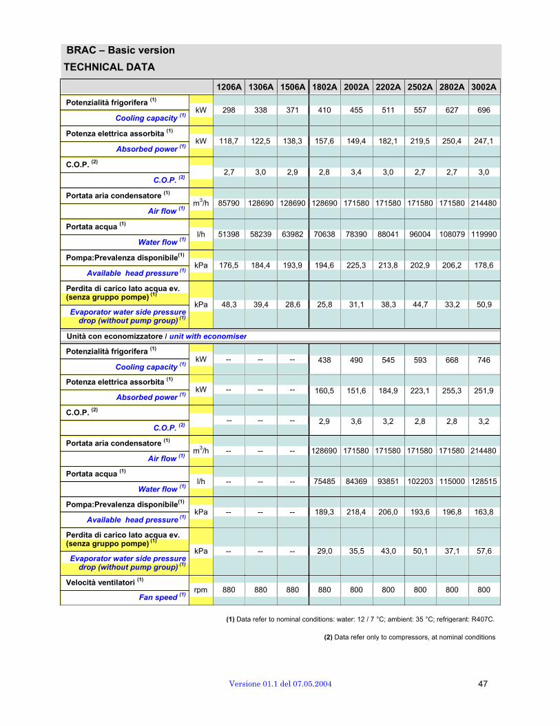
BRAC – Basic version
TECHNICAL DATA Potenzialità frigorifera
(1)
Cooling capacity (1)
Potenza elettrica assorbita (1)
Absorbed power (1)
C.O.P. (2)
C.O.P. (2)
Portata aria condensatore (1)
Air flow (1)
Portata acqua (1)
Water flow (1)
Pompa:Prevalenza disponibile(1)
Available head pressure (1)
Perdita di carico lato acqua ev. (senza gruppo pompe)
(1)
Evaporator water side pressuredrop (without pump group)
(1)
1206A 1306A 1506A 1802A 2002A 2202A 2502A 2802A 3002A
kW 298 338 371 410 455 511 557 627 696
kW 118,7 122,5 138,3 157,6 149,4 182,1 219,5 250,4 247,1
2,7 3,0 2,9 2,8 3,4 3,0 2,7 2,7 3,0 m3/h 85790 128690 128690 128690 171580 171580 171580 171580 214480
l/h 51398 58239 63982 70638 78390 88041 96004 108079 119990
kPa 176,5 184,4 193,9 194,6 225,3 213,8 202,9 206,2 178,6
kPa 48,3 39,4 28,6 25,8 31,1 38,3 44,7 33,2 50,9
Unità con economizzatore / unit with economiser
Potenzialità frigorifera (1)
Cooling capacity (1)
Potenza elettrica assorbita (1)
Absorbed power (1)
C.O.P. (2)
C.O.P. (2)
Portata aria condensatore (1)
Air flow (1)
Portata acqua (1)
Water flow (1)
Pompa:Prevalenza disponibile(1)
Available head pressure (1)
Perdita di carico lato acqua ev. (senza gruppo pompe)
(1)
Evaporator water side pressuredrop (without pump group)
(1)
Velocità ventilatori (1)
Fan speed (1)
kW -- -- -- 438 490 545 593 668 746 kW -- -- -- 160,5 151,6 184,9 223,1 255,3 251,9
-- -- -- 2,9 3,6 3,2 2,8 2,8 3,2 m3/h -- -- -- 128690 171580 171580 171580 171580 214480
l/h -- -- -- 75485 84369 93851 102203 115000 128515
kPa -- -- -- 189,3 218,4 206,0 193,6 196,8 163,8
kPa -- -- -- 29,0 35,5 43,0 50,1 37,1 57,6 rpm 880 880 880 880 800 800 800 800 800
(1) Data refer to nominal conditions: water: 12 / 7 °C; ambient: 35 °C; refrigerant: R407C.
(2) Data refer only to compressors, at nominal conditions
Versione 01.1 del 07.05.2004 47
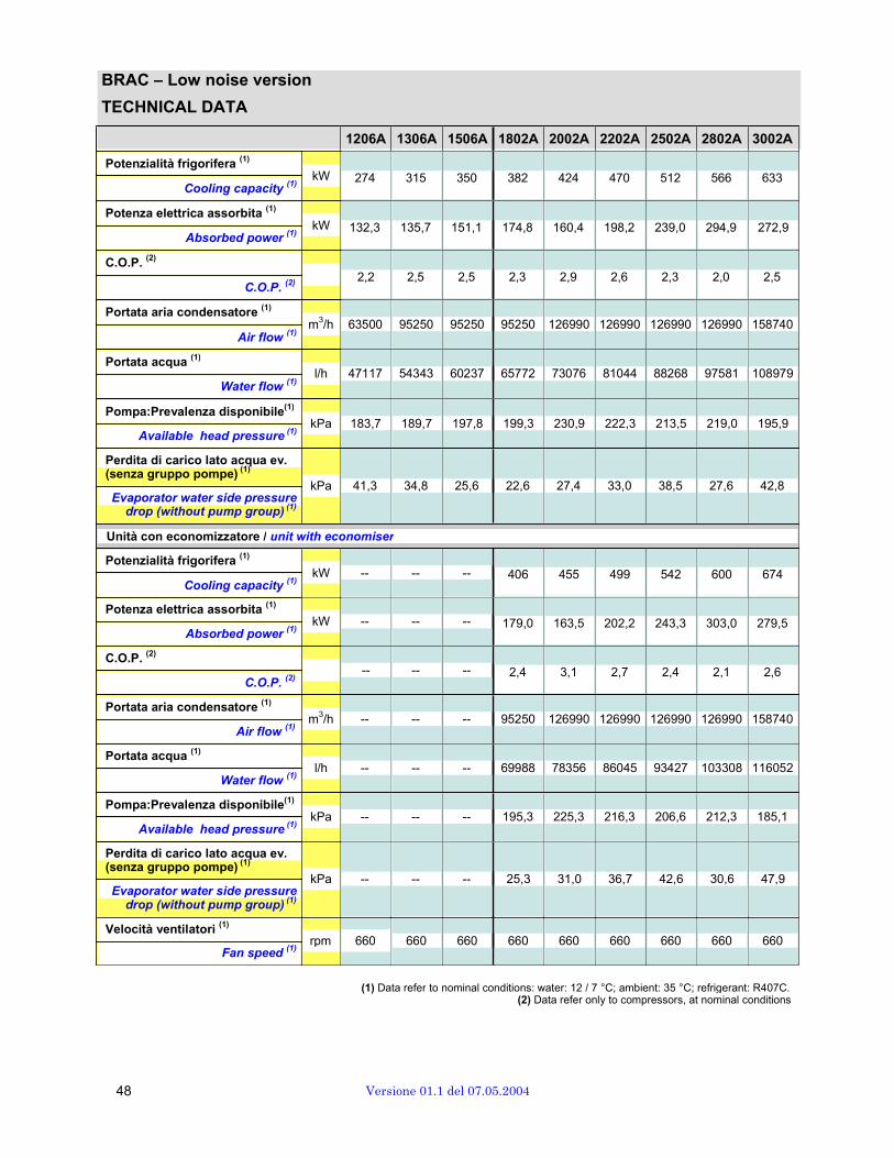
BRAC – Low noise version
TECHNICAL DATA Potenzialità frigorifera
(1)
Cooling capacity (1)
Potenza elettrica assorbita (1)
Absorbed power (1)
C.O.P. (2)
C.O.P. (2)
Portata aria condensatore (1)
1206A 1306A 1506A 1802A 2002A 2202A 2502A 2802A 3002A
kW 274 315 350 382 424 470 512 566 633 kW 132,3 135,7 151,1 174,8 160,4 198,2 239,0 294,9 272,9
2,2 2,5 2,5 2,3 2,9 2,6 2,3 2,0 2,5
Portata acqua (1)
Air flow (1)
Water flow
(1)
m3/h 63500 95250 95250 95250 126990 126990 126990 126990 158740
l/h 47117 54343 60237 65772 73076 81044 88268 97581 108979
Pompa:Prevalenza disponibile(1)
Available head pressure (1)
Perdita di carico lato acqua ev. (senza gruppo pompe)
(1)
Evaporator water side pressuredrop (without pump group)
(1)
kPa 183,7 189,7 197,8 199,3 230,9 222,3 213,5 219,0 195,9
kPa 41,3 34,8 25,6 22,6 27,4 33,0 38,5 27,6 42,8
Unità con economizzatore / unit with economiser
Potenzialità frigorifera (1)
Cooling capacity (1)
Potenza elettrica assorbita (1)
Absorbed power (1)
C.O.P. (2)
C.O.P. (2)
Portata aria condensatore (1)
Air flow (1)
Portata acqua (1)
Water flow (1)
Pompa:Prevalenza disponibile(1)
Available head pressure (1)
Perdita di carico lato acqua ev. (senza gruppo pompe)
(1)
Evaporator water side pressuredrop (without pump group)
(1)
Velocità ventilatori (1)
Fan speed (1)
kW -- -- -- 406 455 499 542 600 674 kW -- -- -- 179,0 163,5 202,2 243,3 303,0 279,5
-- -- -- 2,4 3,1 2,7 2,4 2,1 2,6 m3/h -- -- -- 95250 126990 126990 126990 126990 158740
l/h -- -- -- 69988 78356 86045 93427 103308 116052
kPa -- -- -- 195,3 225,3 216,3 206,6 212,3 185,1
kPa -- -- -- 25,3 31,0 36,7 42,6 30,6 47,9 rpm 660 660 660 660 660 660 660 660 660
(1) Data refer to nominal conditions: water: 12 / 7 °C; ambient: 35 °C; refrigerant: R407C. (2) Data refer only to compressors, at nominal conditions
48 Versione 01.1 del 07.05.2004

BRAT – Basic version
TECHNICAL DATA Potenzialità frigorifera
(1)
Cooling capacity (1)
Potenza elettrica assorbita (1)
Absorbed power (1)
C.O.P. (2)
C.O.P. (2)
Portata aria condensatore (1)
Air flow (1)
Portata acqua (1)
Water flow (1)
Pompa:Prevalenza disponibile(1)
Available head pressure (1)
Perdita di carico lato acqua ev. (senza gruppo pompe)
(1)
Evaporator water side pressuredrop (without pump group)
(1)
1206A 1306A 1506A 1802A 2002A 2202A 2502A 2802A 3002A
kW 317 351 378 415 454 511 577 638 696 kW 108,3 123,1 136,5 146,5 147,7 182,5 205,9 240,3 241,9
3,2 3,1 3,0 3,1 3,4 3,0 3,1 2,9 3,1 m3/h 128690 128690 128690 171580 171580 171580 214480 214480 214480
l/h 54591 60428 65125 71540 78291 88093 99321 109910 119948
kPa 170,6 181,3 192,7 193,7 225,4 213,7 198,0 203,8 178,7
kPa 53,8 42,1 29,5 26,3 31,0 38,3 47,6 34,2 50,9
Unità con economizzatore / unit with economiser
Potenzialità frigorifera (1)
Cooling capacity (1)
Potenza elettrica assorbita (1)
Absorbed power (1)
C.O.P. (2)
C.O.P. (2)
Portata aria condensatore (1)
Air flow (1)
Portata acqua (1)
Water flow (1)
Pompa:Prevalenza disponibile(1)
Available head pressure (1)
Perdita di carico lato acqua ev. (senza gruppo pompe)
(1)
Evaporator water side pressuredrop (without pump group)
(1)
Velocità ventilatori (1)
Fan speed (1)
kW -- -- -- 445 489 545 614 679 746 kW -- -- -- 148,3 149,8 185,4 208,2 244,1 246,4
-- -- -- 3,3 3,6 3,2 3,2 3,0 3,3 m3/h -- -- -- 171580 171580 171580 214480 214480 214480
l/h -- -- -- 76598 84308 93895 105801 117016 128538
kPa -- -- -- 188,1 218,5 205,9 187,8 193,8 163,7
kPa -- -- -- 29,8 35,4 43,0 53,3 38,3 57,6 rpm 880 880 880 880 800 800 800 800 800
(1) Data refer to nominal conditions: water: 12 / 7 °C; ambient: 35 °C; refrigerant: R407C. (2) Data refer only to compressors, at nominal conditions
Versione 01.1 del 07.05.2004 49
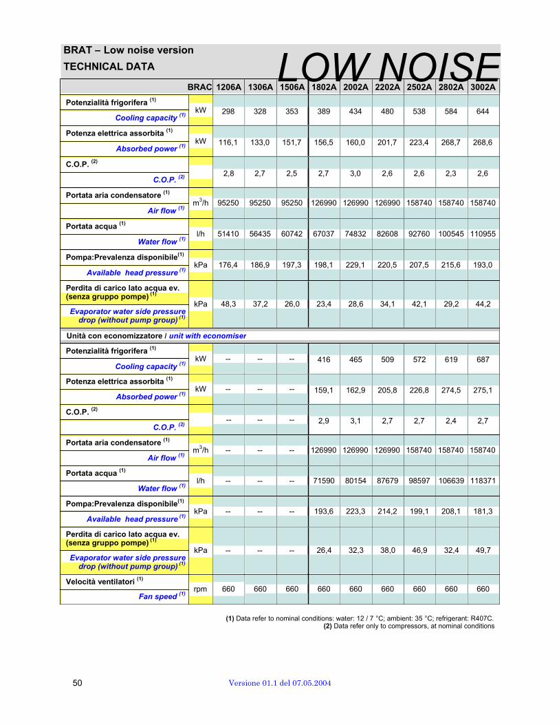
BRAT – Low noise version
TECHNICAL DATA LOW NOISE Potenzialità frigorifera
(1)
Cooling capacity (1)
Potenza elettrica assorbita (1)
Absorbed power (1)
C.O.P. (2)
C.O.P. (2)
Portata aria condensatore (1)
Air flow (1)
Portata acqua (1)
Water flow (1)
Pompa:Prevalenza disponibile(1)
Available head pressure (1)
Perdita di carico lato acqua ev. (senza gruppo pompe)
(1)
Evaporator water side pressuredrop (without pump group)
(1)
BRAC 1206A 1306A 1506A 1802A 2002A 2202A 2502A 2802A 3002A
kW 298 328 353 389 434 480 538 584 644
kW 116,1 133,0 151,7 156,5 160,0 201,7 223,4 268,7 268,6
2,8 2,7 2,5 2,7 3,0 2,6 2,6 2,3 2,6
m3/h 95250 95250 95250 126990 126990 126990 158740 158740 158740
l/h 51410 56435 60742 67037 74832 82608 92760 100545 110955
kPa 176,4 186,9 197,3 198,1 229,1 220,5 207,5 215,6 193,0
kPa 48,3 37,2 26,0 23,4 28,6 34,1 42,1 29,2 44,2
Unità con economizzatore / unit with economiser
Potenzialità frigorifera (1)
Cooling capacity (1)
Potenza elettrica assorbita (1)
Absorbed power (1)
C.O.P. (2)
C.O.P. (2)
Portata aria condensatore (1)
Air flow (1)
Portata acqua (1)
Water flow (1)
Pompa:Prevalenza disponibile(1)
Available head pressure (1)
Perdita di carico lato acqua ev. (senza gruppo pompe)
(1)
Evaporator water side pressuredrop (without pump group)
(1)
Velocità ventilatori (1)
Fan speed (1)
kW -- -- -- 416 465 509 572 619 687 kW -- -- -- 159,1 162,9 205,8 226,8 274,5 275,1
-- -- -- 2,9 3,1 2,7 2,7 2,4 2,7 m3/h -- -- -- 126990 126990 126990 158740 158740 158740
l/h -- -- -- 71590 80154 87679 98597 106639 118371
kPa -- -- -- 193,6 223,3 214,2 199,1 208,1 181,3
kPa -- -- -- 26,4 32,3 38,0 46,9 32,4 49,7 rpm 660 660 660 660 660 660 660 660 660
(1) Data refer to nominal conditions: water: 12 / 7 °C; ambient: 35 °C; refrigerant: R407C. (2) Data refer only to compressors, at nominal conditions
50 Versione 01.1 del 07.05.2004

BRAT – Ultra-low noise version
TECHNICAL DAUTA LTRA-LOW NOISEPotenzialità frigorifera
(1)
Cooling capacity (1)
Potenza elettrica assorbita (1)
Absorbed power (1)
C.O.P. (2)
C.O.P. (2)
Portata aria condensatore (1)
Air flow (1)
Portata acqua (1)
Water flow (1)
Pompa:Prevalenza disponibile(1)
Available head pressure (1)
Perdita di carico lato acqua ev. (senza gruppo pompe)
(1)
Evaporator water side pressuredrop (without pump group)
(1)
1206A 1306A 1506A 1802A 2002A 2202A 2502A 2802A 3002A
kW 282 311 336 368 402 455 500 547 599 kW 122,7 141,5 159,7 165,4 169,3 208,4 233,5 283,5 289,5
2,5 2,4 2,3 2,4 2,6 2,3 2,3 2,1 2,2 m3/h 78670 78670 78670 104890 104890 104890 131110 131110 131110
l/h 48922 53968 58353 63952 69506 78758 86794 95112 103560
kPa 177,2 188,4 199,8 201,4 234,6 223,0 211,5 -32,2 196,6
kPa 53,9 41,9 29,6 26,3 30,8 38,4 45,6 32,2 48,0
Unità con economizzatore / unit with economiser
Potenzialità frigorifera (1)
Cooling capacity (1)
Potenza elettrica assorbita (1)
Absorbed power (1)
C.O.P. (2)
C.O.P. (2)
Portata aria condensatore (1)
Air flow (1)
Portata acqua (1)
Water flow (1)
Pompa:Prevalenza disponibile(1)
Available head pressure (1)
Perdita di carico lato acqua ev. (senza gruppo pompe)
(1)
Evaporator water side pressuredrop (without pump group)
(1)
Velocità ventilatori (1)
Fan speed (1)
kW -- -- -- 395 431 484 534 584 638 kW -- -- -- 169,3 173,4 213,6 238,4 291,7 297,9
-- -- -- 2,6 2,7 2,4 2,4 2,1 2,3 m3/h -- -- -- 104890 104890 104890 131110 131110 131110
l/h -- -- -- 68079 74316 83322 92011 100555 109983
kPa -- -- -- 197,2 229,6 219,6 208,5 194,4
kPa -- -- -- 24,1 28,2 34,7 41,4 29,2 43,5 rpm 550 550 550 550 550 550 550 550 550
(1) Data refer to nominal conditions: water: 12 / 7 °C; ambient: 35 °C; refrigerant: R407C. (2) Data refer only to compressors, at nominal conditions
Versione 01.1 del 07.05.2004 51
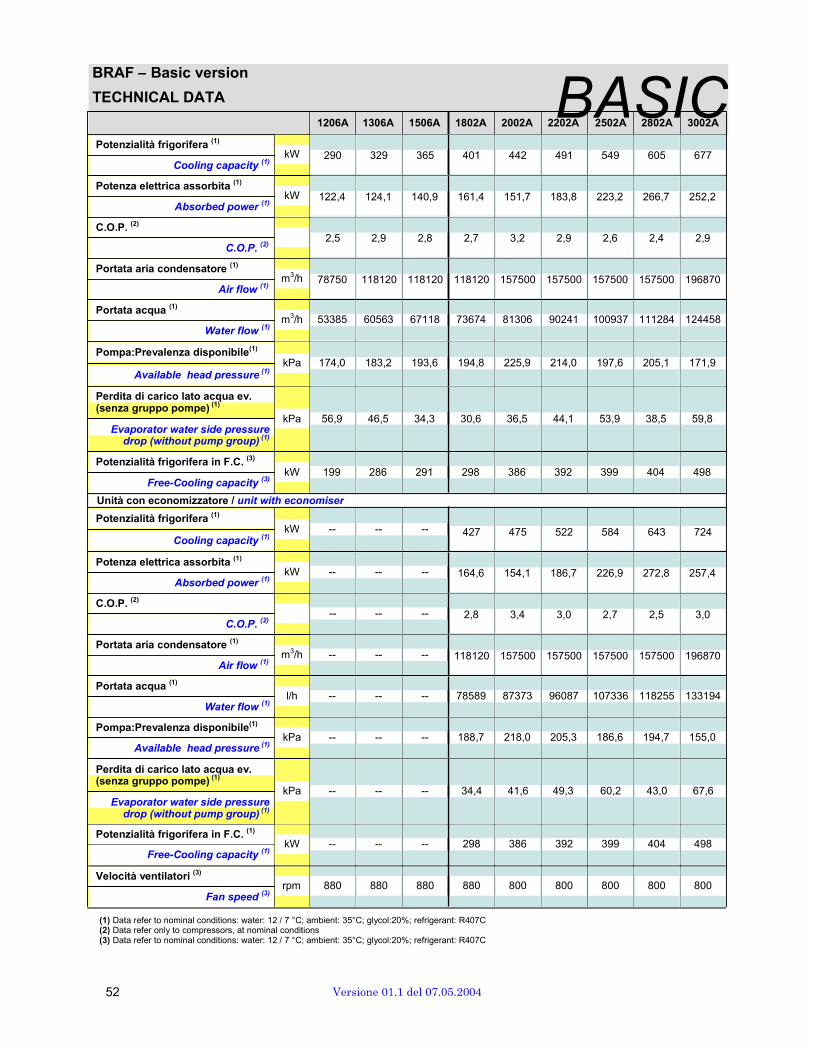
BRAF – Basic version
TECHNICAL DATA
Potenzialità frigorifera
(1)
Cooling capacity (1)
Potenza elettrica assorbita (1)
Absorbed power (1)
C.O.P. (2)
C.O.P. (2)
Portata aria condensatore (1)
Air flow (1)
Portata acqua (1)
Water flow (1)
Pompa:Prevalenza disponibile(1)
Available head pressure (1)
1206A 1306A 1506A 1802A 2002A 22B02A
A2502A
S2802AIC
3002A
kW 290 329 365 401 442 491 549 605 677 kW 122,4 124,1 140,9 161,4 151,7 183,8 223,2 266,7 252,2
2,5 2,9 2,8 2,7 3,2 2,9 2,6 2,4 2,9 m3/h 78750 118120 118120 118120 157500 157500 157500 157500 196870 m3/h 53385 60563 67118 73674 81306 90241 100937 111284 124458
kPa 174,0 183,2 193,6 194,8 225,9 214,0 197,6 205,1 171,9
Perdita di carico lato acqua ev. (senza gruppo pompe)
(1)
Evaporator water side pressure drop (without pump group)
(1)
Potenzialità frigorifera in F.C. (3)
Free-Cooling capacity (3)
kPa 56,9 46,5 34,3 30,6 36,5 44,1 53,9 38,5 59,8 kW 199 286 291 298 386 392 399 404 498
Unità con economizzatore / unit with economiser
Potenzialità frigorifera (1)
Cooling capacity (1)
Potenza elettrica assorbita (1)
Absorbed power (1)
C.O.P. (2)
C.O.P. (2)
Portata aria condensatore (1)
Air flow (1)
Portata acqua (1)
Water flow (1)
Pompa:Prevalenza disponibile(1)
Available head pressure (1)
Perdita di carico lato acqua ev. (senza gruppo pompe)
(1)
Evaporator water side pressure drop (without pump group)
(1)
Potenzialità frigorifera in F.C. (1)
Free-Cooling capacity (1)
Velocità ventilatori (3)
kW -- -- -- 427 475 522 584 643 724 kW -- -- -- 164,6 154,1 186,7 226,9 272,8 257,4
-- -- -- 2,8 3,4 3,0 2,7 2,5 3,0 m3/h -- -- -- 118120 157500 157500 157500 157500 196870 l/h -- -- -- 78589 87373 96087 107336 118255 133194
kPa -- -- -- 188,7 218,0 205,3 186,6 194,7 155,0 kPa -- -- -- 34,4 41,6 49,3 60,2 43,0 67,6 kW -- -- -- 298 386 392 399 404 498 rpm 880 880 880 880 800 800 800 800 800
Fan speed (3)
(1) Data refer to nominal conditions: water: 12 / 7 °C; ambient: 35°C; glycol:20%; refrigerant: R407C (2) Data refer only to compressors, at nominal conditions (3) Data refer to nominal conditions: water: 12 / 7 °C; ambient: 35°C; glycol:20%; refrigerant: R407C
52 Versione 01.1 del 07.05.2004
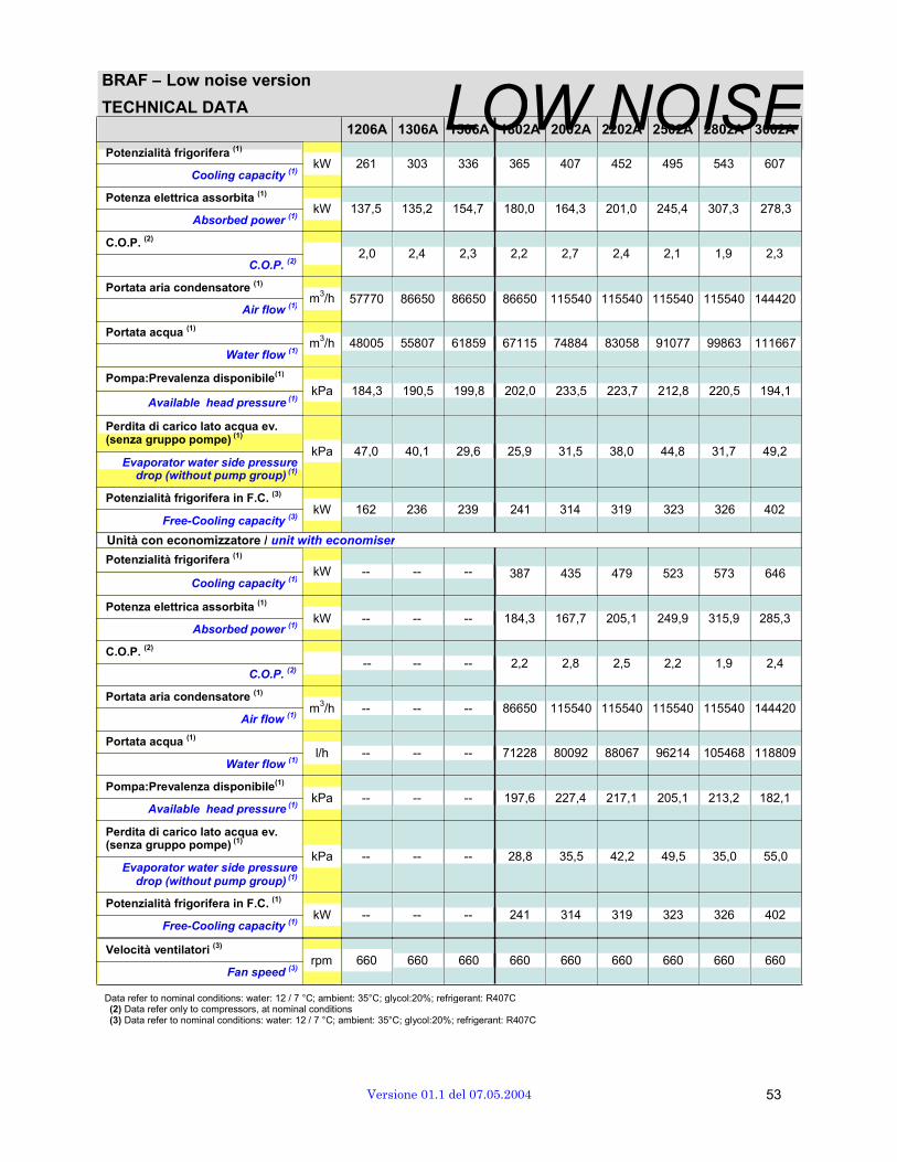
BRAF – Low noise version
TECHNICAL DATA Potenzialità frigorifera
(1)
Cooling capacity (1)
Potenza elettrica assorbita (1)
Absorbed power (1)
C.O.P. (2)
C.O.P. (2)
Portata aria condensatore (1)
1206A 1306A L1506OA 1802WA 2002A 2N202A O2502A I28S02A 3E002A
kW 261 303 336 365 407 452 495 543 607 kW 137,5 135,2 154,7 180,0 164,3 201,0 245,4 307,3 278,3
2,0 2,4 2,3 2,2 2,7 2,4 2,1 1,9 2,3
Portata acqua (1)
Air flow (1)
Water flow
(1)
m3/h 57770 86650 86650 86650 115540 115540 115540 115540 144420 m3/h 48005 55807 61859 67115 74884 83058 91077 99863 111667
Pompa:Prevalenza disponibile(1)
Available head pressure (1)
kPa 184,3 190,5 199,8 202,0 233,5 223,7 212,8 220,5 194,1
Perdita di carico lato acqua ev. (senza gruppo pompe)
(1)
Evaporator water side pressure drop (without pump group)
(1)
Potenzialità frigorifera in F.C. (3)
Free-Cooling capacity (3)
kPa 47,0 40,1 29,6 25,9 31,5 38,0 44,8 31,7 49,2 kW 162 236 239 241 314 319 323 326 402
Unità con economizzatore / unit with economiser
Potenzialità frigorifera (1)
Cooling capacity (1)
Potenza elettrica assorbita (1)
Absorbed power (1)
C.O.P. (2)
C.O.P. (2)
Portata aria condensatore (1)
Air flow (1)
Portata acqua (1)
Water flow (1)
Pompa:Prevalenza disponibile(1)
Available head pressure (1)
Perdita di carico lato acqua ev. (senza gruppo pompe)
(1)
Evaporator water side pressure drop (without pump group)
(1)
Potenzialità frigorifera in F.C. (1)
Free-Cooling capacity (1)
Velocità ventilatori (3)
kW -- -- -- 387 435 479 523 573 646 kW -- -- -- 184,3 167,7 205,1 249,9 315,9 285,3
-- -- -- 2,2 2,8 2,5 2,2 1,9 2,4 m3/h -- -- -- 86650 115540 115540 115540 115540 144420 l/h -- -- -- 71228 80092 88067 96214 105468 118809
kPa -- -- -- 197,6 227,4 217,1 205,1 213,2 182,1 kPa -- -- -- 28,8 35,5 42,2 49,5 35,0 55,0 kW -- -- -- 241 314 319 323 326 402 rpm 660 660 660 660 660 660 660 660 660
Fan speed (3)
Data refer to nominal conditions: water: 12 / 7 °C; ambient: 35°C; glycol:20%; refrigerant: R407C (2) Data refer only to compressors, at nominal conditions (3) Data refer to nominal conditions: water: 12 / 7 °C; ambient: 35°C; glycol:20%; refrigerant: R407C
Versione 01.1 del 07.05.2004 53
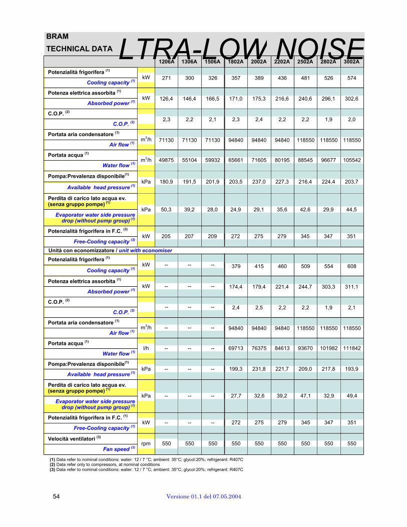
BRAM
TECHNICAL DATA LTRA-LOW NOISEPotenzialità frigorifera
(1)
Cooling capacity (1)
Potenza elettrica assorbita (1)
Absorbed power (1)
C.O.P. (2)
C.O.P. (2)
Portata aria condensatore (1)
Air flow (1)
Portata acqua (1)
Water flow (1)
Pompa:Prevalenza disponibile(1)
Available head pressure (1)
1206A 1306A 1506A 1802A 2002A 2202A 2502A 2802A 3002A
kW 271 300 326 357 389 436 481 526 574 kW 126,4 146,4 166,5 171,0 175,3 216,6 240,6 296,1 302,6
2,3 2,2 2,1 2,3 2,4 2,2 2,2 1,9 2,0 m3/h 71130 71130 71130 94840 94840 94840 118550 118550 118550 m3/h 49875 55104 59932 65661 71605 80195 88545 96677 105542
kPa 180,9 191,5 201,9 203,5 237,0 227,3 216,4 224,4 203,7
Perdita di carico lato acqua ev. (senza gruppo pompe)
(1)
Evaporator water side pressure drop (without pump group)
(1)
Potenzialità frigorifera in F.C. (3)
Free-Cooling capacity (3)
kPa 50,3 39,2 28,0 24,9 29,1 35,6 42,6 29,9 44,5 kW 205 207 209 272 275 279 345 347 351
Unità con economizzatore / unit with economiser
Potenzialità frigorifera (1)
Cooling capacity (1)
Potenza elettrica assorbita (1)
Absorbed power (1)
C.O.P. (2)
C.O.P. (2)
Portata aria condensatore (1)
Air flow (1)
Portata acqua (1)
Water flow (1)
Pompa:Prevalenza disponibile(1)
Available head pressure (1)
Perdita di carico lato acqua ev. (senza gruppo pompe)
(1)
Evaporator water side pressure drop (without pump group)
(1)
Potenzialità frigorifera in F.C. (1)
Free-Cooling capacity (1)
Velocità ventilatori (3)
kW -- -- -- 379 415 460 509 554 608 kW -- -- -- 174,4 179,4 221,4 244,7 303,3 311,1
-- -- -- 2,4 2,5 2,2 2,2 1,9 2,1 m3/h -- -- -- 94840 94840 94840 118550 118550 118550 l/h -- -- -- 69713 76375 84613 93670 101982 111842
kPa -- -- -- 199,3 231,8 221,7 209,0 217,8 193,9 kPa -- -- -- 27,7 32,6 39,2 47,1 32,9 49,4 kW -- -- -- 272 275 279 345 347 351 rpm 550 550 550 550 550 550 550 550 550
Fan speed (3)
(1) Data refer to nominal conditions: water: 12 / 7 °C; ambient: 35°C; glycol:20%; refrigerant: R407C (2) Data refer only to compressors, at nominal conditions (3) Data refer to nominal conditions: water: 12 / 7 °C; ambient: 35°C; glycol:20%; refrigerant: R407C
54 Versione 01.1 del 07.05.2004

ELECTRICAL DATA
Basic version - BRAC
ELECTRICAL DATA BASIC Compressori circuito 1 Compressori circuito 2 Ventilatore
MODELLO OP(1)
OA(1)
FLI(2)
FLA(2) LRA
(5) OP
(1) OA
(1) FLI
(2) FLA
(2) LRA
(5) No. OP OA FLI FLA
1206A 55,7 96,4 24 35,7 215 55,7 96,4 24 35,7 215 4 1,8 3,4 2 4
1306A 55,8 109,4 24/29 49,3 270 55,8 109,4 24/29 49,3 270 6 1,8 3,4 2 4
1506A 63,7 118,1 29 49,3 270 63,7 118,1 29 49,3 270 6 1,8 3,4 2 4
1802A 73,4 109,6 96 155 439 73,4 109,6 96 155 439 6 1,8 3,4 2 4
2002A 67,5 109,6 96 155 439 67,5 109,6 96 155 439 8 1,8 3,4 2 4
2202A 83,8 138,7 110 182 520 83,8 138,7 110 182 520 8 1,8 3,4 2 4
2502A 102,6 170,7 132 215 612 102,6 170,7 132 215 612 8 1,8 3,4 2 4
2802A 118,0 193,0 150 231 665 118,0 193,0 150 231 665 8 1,8 3,4 2 4
3002A 114,5 188,2 150 231 665 114,5 188,2 150 231 665 10 1,8 3,4 2 4
MODELS OP(1)
OA(1)
FLI(2) FLA
(2) LRA
(5) OP
(1) OA
(1) FLI
(2) FLA
(2) LRA
(5) Nr. OP OA FLI FLA
Compressors circuit Nr.1 Compressors circuit Nr.2 Fan
Unità completa (base) / Complete unit (basic version) MODELLO 1206A 1306A 1506A 1802A 2002A 2202A 2502A 2802A 3002A MODELS
OP [kW] 118,0 121,5 137,3 156,6 148,1 180,8 218,2 249,1 245,4 OP [kW]
OA [A] 239,3 256,6 256,6 239,7 246,5 304,7 368,6 413,3 410,4 OA [A]
FLI [kW] 152 167 182 204,0 208,0 236,0 280,0 316,0 320,0 FLI [kW]
FLA [A] 230,2 265,4 319,8 348,0 356,0 396,0 462,0 494,0 502,0 FLA [A]
LRA (4) [A] 409,5 486,1 540,5 609,0 617,0 734,0 859,0 928,0 936,0 LRA
(4) [A]
Gruppo Pompe (opzionali) (2) / Pump group (optional)
(2)
MODELLO 1206A 1306A 1506A 1802A 2002A 2202A 2502A 2802A 3002A MODELS
FLA [A] 20 20 20 20 23 23 23 23 23 FLA [A]
LRA [A] 190 190 190 190 190 241,5 241,5 241,5 241,5 LRA [A]
(1) For each circuit. Note: for units equipped with economiser power and current increase of 3%
(2) For each compressor (3) Only 1 pump runs when the unit is in operattion; even for units
with two pumps in this case 1 pump is always in stand-by (4) Calculated during critical working conditions: all fans ON , three
compressors running along with the last compressor swiched- on - all fans running at maximum speed.
(5) LRA refers to the compressor with largest dimension OP Operating input power at nominal conditions (water 12 / 7°C,
outdoor temperature 35°C; refrigerant R407C) [kW] OA Operating current at nominal conditions [A] FLI Full load input power [kW] FLA Full load current [A] LRA Start-up current [A]
Versione 01.1 del 07.05.2004 55

ELECTRICAL DATA
Low noise version - BRAC
ELECTRICAL DATA LOW NOISE Compressori circuito 1 Compressori circuito 2 Ventilatore
MODELLO OP(1)
OA(1)
FLI(2)
FLA(2) LRA
(5) OP
(1) OA
(1) FLI
(2) FLA
(2) LRA
(5) No. OP OA FLI FLA
1206A 62,5 105,0 24 35,7 215 62,5 105,0 24 35,7 215 4 1,2 2,2 1,25 2,3
1306A 62,4 117,7 24/29 49,3 270 62,4 117,7 24/29 49,3 270 6 1,2 2,2 1,25 2,3
1506A 70,1 129,9 29 49,3 270 70,1 129,9 29 49,3 270 6 1,2 2,2 1,25 2,3
1802A 82,0 117,4 96 155 439 82,0 117,4 96 155 439 6 1,2 2,2 1,25 2,3
2002A 73,0 117,4 96 155 439 73,0 117,4 96 155 439 8 1,2 2,2 1,25 2,3
2202A 91,9 149,4 110 182 520 91,9 149,4 110 182 520 8 1,2 2,2 1,25 2,3
2502A 112,3 186,3 132 215 612 112,3 186,3 132 215 612 8 1,2 2,2 1,25 2,3
2802A 140,3 222,6 150 231 665 140,3 222,6 150 231 665 8 1,2 2,2 1,25 2,3
3002A 127,4 205,6 150 231 665 127,4 205,6 150 231 665 10 1,2 2,2 1,25 2,3
MODELS OP(1)
OA(1)
FLI(2) FLA
(2) LRA
(5) OP
(1) OA
(1) FLI
(2) FLA
(2) LRA
(5) Nr. OP OA FLI FLA
Compressors circuit Nr.1 Compressors circuit Nr.2 Fan
Unità completa (base) / Complete unit (basic version) MODELLO 1206A 1306A 1506A 1802A 2002A 2202A 2502A 2802A 3002A MODELS
OP [kW] 129,5 131,4 146,9 170,6 154,8 192,6 233,4 289,3 265,8 OP [kW]
OA [A] 257,8 282,2 282,2 257,2 264,7 328,6 402,4 475,2 448,5 OA [A]
FLI [kW] 149,0 166,5 181,5 199,5 202 230 274 310 312,5 FLI [kW]
FLA [A] 223,4 268,8 309,6 323,8 328,4 382,4 448,4 480,4 485,0 FLA [A]
LRA (4) [A] 402,7 475,9 530,3 598,8 603,4 720,4 845,4 914,4 919,0 LRA
(4) [A]
Gruppo Pompe (opzionali) (3) / Pump group (optional)
(3)
MODELLO 1206A 1306A 1506A 1802A 2002A 2202A 2502A 2802A 3002A MODELS
FLA [A] 20 20 20 20 23 23 23 23 23 FLA [A]
LRA [A] 190 190 190 190 190 241,5 241,5 241,5 241,5 LRA [A]
(1) For each circuit. Note: for units equipped with economiser power and current increase of 3%
(2) For each compressor (3) Only 1 pump runs when the unit is in operattion; even for units
with two pumps in this case 1 pump is always in stand-by (4) Calculated during critical working conditions: all fans ON , three
compressors running along with the last compressor swiched-on - all fans running at maximum speed.
(5) LRA refers to the compressor with largest dimension OP Operating input power at nominal conditions (water 12 / 7°C,
outdoor temperature 35°C; refrigerant R407C) [kW]OA Operating current at nominal conditions [A] FLI Full load input power [kW] FLA Full load current [A] LRA Start-up current [A]
56 Versione 01.1 del 07.05.2004

ELECTRICAL DATA
Basic version - BRAT
ELECTRICAL DATA BASIC Compressori circuito 1 Compressori circuito 2 Ventilatore
MODELLO OP(1)
OA(1)
FLI(2)
FLA(2) LRA
(5) OP
(1) OA
(1) FLI
(2) FLA
(2) LRA
(5) No. OP OA FLI FLA
1206A 48,8 96,8 24 35,7 215 48,8 96,8 24 35,7 215 6 1,8 3,4 2 4
1306A 56,1 108,3 24/29 49,3 270 56,1 108,3 24/29 49,3 270 6 1,8 3,4 2 4
1506A 62,9 107,3 29 49,3 270 62,9 107,3 29 49,3 270 6 1,8 3,4 2 4
1802A 66,0 108,4 96 155 439 66,0 108,4 96 155 439 8 1,8 3,4 2 4
2002A 66,7 108,4 96 155 439 66,7 108,4 96 155 439 8 1,8 3,4 2 4
2202A 84,1 139,0 110 182 520 84,1 139,0 110 182 520 8 1,8 3,4 2 4
2502A 93,9 157,2 132 215 612 93,9 157,2 132 215 612 10 1,8 3,4 2 4
2802A 111,2 183,5 150 231 665 111,2 183,5 150 231 665 10 1,8 3,4 2 4
3002A 112,0 184,6 150 231 665 112,0 184,6 150 231 665 10 1,8 3,4 2 4
MODELS OP(1)
OA(1)
FLI(2) FLA
(2) LRA
(5) OP
(1) OA
(1) FLI
(2) FLA
(2) LRA
(5) Nr. OP OA FLI FLA
Compressors circuit Nr.1)
Compressors circuit Nr.2 Fan
Unità completa (base) / Complete unit (basic version) MODELLO 1206A 1306A 1506A 1802A 2002A 2202A 2502A 2802A 3002A MODELS
OP [kW] 107,4 122,1 135,6 145,2 146,4 181,2 204,2 238,7 240,3 OP [kW]
OA [A] 237,1 235,2 235,2 244,0 244,0 305,3 348,5 401,0 403,4 OA [A]
FLI [kW] 156 167 182 210,0 208,0 236,0 284,0 320,0 320,0 FLI [kW]
FLA [A] 238,2 265,4 319,8 356,0 356,0 396,0 470,0 502,0 502,0 FLA [A]
LRA (4) [A] 417,5 486,1 540,5 617,0 617,0 734,0 867,0 936,0 936,0 LRA
(4) [A]
Gruppo Pompe (opzionali) (3) / Pump group (optional)
(3)
MODELLO 1206A 1306A 1506A 1802A 2002A 2202A 2502A 2802A 3002A MODELS
FLA [A] 20 20 20 20 23 23 23 23 23 FLA [A]
LRA [A] 190 190 190 190 190 241,5 241,5 241,5 241,5 LRA [A]
(1) For each circuit. Note: for units equipped with economiser power and current increase of 3%
(2) For each compressor (3) Only 1 pump runs when the unit is in operattion; even for units
with two pumps in this case 1 pump is always in stand-by (4) Calculated during critical working conditions: all fans ON , three
compressors running along with the last compressor swiched- on - all fans running at maximum speed.
(5) LRA refers to the compressor with largest dimension OP Operating input power at nominal conditions (water 12 / 7°C,
outdoor temperature 35°C; refrigerant R407C) [kW] OA Operating current at nominal conditions [A] FLI Full load input power [kW] FLA Full load current [A]
Versione 01.1 del 07.05.2004 57

ELECTRICAL DATA
Low noise version - BRAT
ELECTRICAL DATA LOW NOISE Compressori circuito 1
(1) Compressori circuito 2
(1) Ventilatore
MODELLO OP(1)
OA(1)
FLI(2)
FLA(2) LRA
(5) OP
(1) OA
(1) FLI
(2) FLA
(2) LRA
(5) No. OP OA FLI FLA
1206A 52,7 103,3 24 35,7 215 52,7 103,3 24 35,7 215 6 1,2 2,2 1,25 2,3
1306A 61,1 118,0 24/29 49,3 270 61,1 118,0 24/29 49,3 270 6 1,2 2,2 1,25 2,3
1506A 70,4 114,9 29 49,3 270 70,4 114,9 29 49,3 270 6 1,2 2,2 1,25 2,3
1802A 71,1 117,0 96 155 439 71,1 117,0 96 155 439 8 1,2 2,2 1,25 2,3
2002A 72,8 117,0 96 155 439 72,8 117,0 96 155 439 8 1,2 2,2 1,25 2,3
2202A 93,6 151,6 110 182 520 93,6 151,6 110 182 520 8 1,2 2,2 1,25 2,3
2502A 102,7 170,9 132 215 612 102,7 170,9 132 215 612 10 1,2 2,2 1,25 2,3
2802A 125,4 203,2 150 231 665 125,4 203,2 150 231 665 10 1,2 2,2 1,25 2,3
3002A 125,3 202,7 150 231 665 125,3 202,7 150 231 665 10 1,2 2,2 1,25 2,3
MODELS OP(1)
OA(1)
FLI(2) FLA
(2) LRA
(5) OP
(1) OA
(1) FLI
(2) FLA
(2) LRA
(5) Nr. OP OA FLI FLA
Compressors circuit Nr.1 Compressors circuit Nr.2 Fan
Unità completa (base) / Complete unit (basic version) MODELLO 1206A 1306A 1506A 1802A 2002A 2202A 2502A 2802A 3002A MODELS
OP [kW] 111,9 128,8 147,4 150,9 154,3 196,1 216,3 261,7 261,6 OP [kW]
OA [A] 258,5 252,2 252,2 263,9 263,9 333,1 379,2 443,7 442,8 OA [A]
FLI [kW] 151,5 166,5 181,5 202 202 230 276,5 312,5 312,5 FLI [kW]
FLA [A] 228 268,8 309,6 328,2 328,4 382,4 453,0 485,0 485,0 FLA [A]
LRA (4) [A] 402,7 475,9 530,3 598,8 603,4 720,4 845,4 914,4 919,0 LRA
(4) [A]
Gruppo Pompe (opzionali) (3) / Pump group (optional)
(3)
MODELLO 1206A 1306A 1506A 1802A 2002A 2202A 2502A 2802A 3002A MODELS
FLA [A] 20 20 20 20 23 23 23 23 23 FLA [A]
LRA [A] 190 190 190 190 190 241,5 241,5 241,5 241,5 LRA [A]
(1) For each circuit. Note: for units equipped with economiser power and current increase of 3%
(2) For each compressor (3) Only 1 pump runs when the unit is in operattion; even for units
with two pumps in this case 1 pump is always in stand-by (4) Calculated during critical working conditions: all fans ON , three
compressors running along with the last compressor swiched- on - all fans running at maximum speed.
(5) LRA refers to the compressor with largest dimension OP Operating input power at nominal conditions (water 12 / 7°C,
outdoor temperature 35°C; refrigerant R407C) [kW] OA Operating current at nominal conditions [A] FLI Full load input power [kW] FLA Full load current [A]
58 Versione 01.1 del 07.05.2004
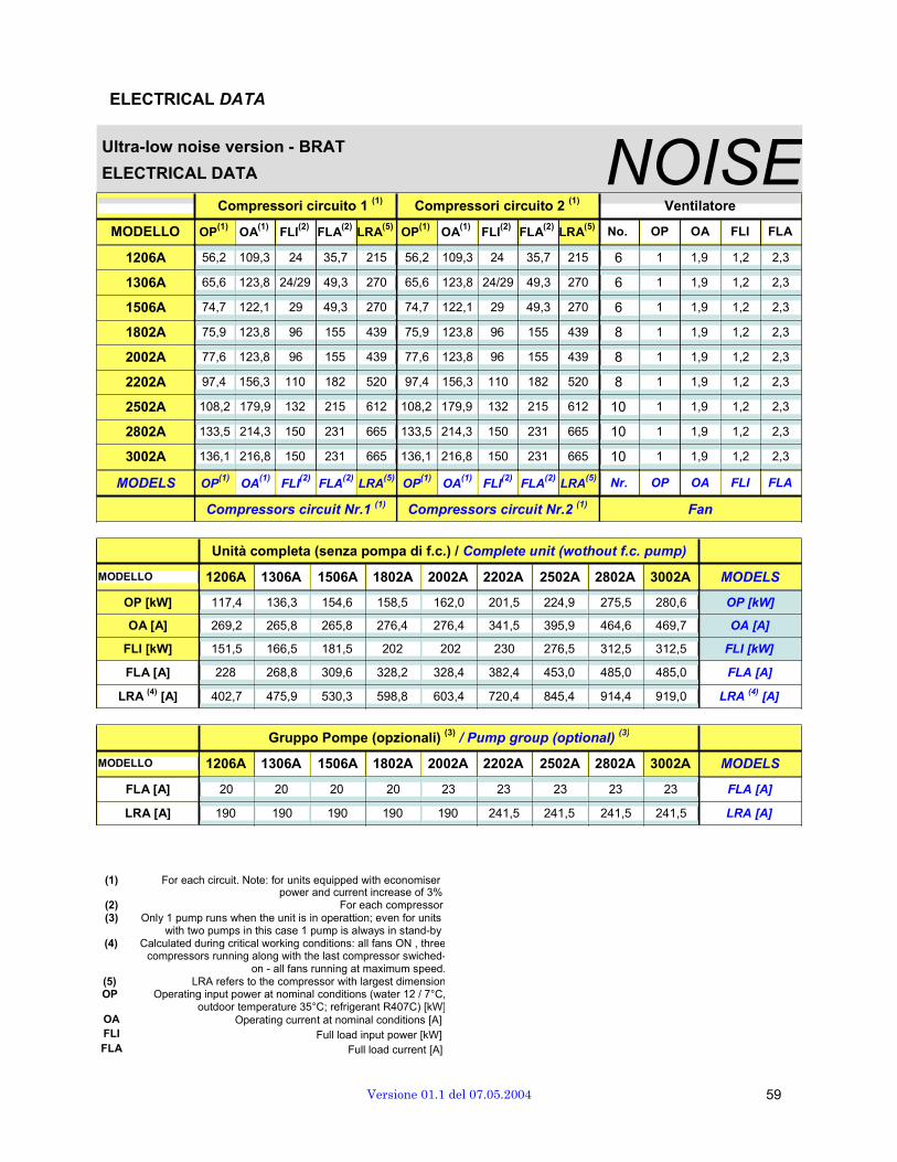
ELECTRICAL DATA Ultra-low noise version - BRAT
ELECTRICAL DATA NOISECompressori circuito 1
(1) Compressori circuito 2
(1) Ventilatore
MODELLO OP(1)
OA(1)
FLI(2)
FLA(2) LRA
(5) OP
(1) OA
(1) FLI
(2) FLA
(2) LRA
(5) No. OP OA FLI FLA
1206A 56,2 109,3 24 35,7 215 56,2 109,3 24 35,7 215 6 1 1,9 1,2 2,3
1306A 65,6 123,8 24/29 49,3 270 65,6 123,8 24/29 49,3 270 6 1 1,9 1,2 2,3
1506A 74,7 122,1 29 49,3 270 74,7 122,1 29 49,3 270 6 1 1,9 1,2 2,3
1802A 75,9 123,8 96 155 439 75,9 123,8 96 155 439 8 1 1,9 1,2 2,3
2002A 77,6 123,8 96 155 439 77,6 123,8 96 155 439 8 1 1,9 1,2 2,3
2202A 97,4 156,3 110 182 520 97,4 156,3 110 182 520 8 1 1,9 1,2 2,3
2502A 108,2 179,9 132 215 612 108,2 179,9 132 215 612 10 1 1,9 1,2 2,3
2802A 133,5 214,3 150 231 665 133,5 214,3 150 231 665 10 1 1,9 1,2 2,3
3002A 136,1 216,8 150 231 665 136,1 216,8 150 231 665 10 1 1,9 1,2 2,3
MODELS OP(1)
OA(1)
FLI(2) FLA
(2) LRA
(5) OP
(1) OA
(1) FLI
(2) FLA
(2) LRA
(5) Nr. OP OA FLI FLA
Compressors circuit Nr.1 (1)
Compressors circuit Nr.2 (1)
Fan
Unità completa (senza pompa di f.c.) / Complete unit (wothout f.c. pump) MODELLO 1206A 1306A 1506A 1802A 2002A 2202A 2502A 2802A 3002A MODELS
OP [kW] 117,4 136,3 154,6 158,5 162,0 201,5 224,9 275,5 280,6 OP [kW]
OA [A] 269,2 265,8 265,8 276,4 276,4 341,5 395,9 464,6 469,7 OA [A]
FLI [kW] 151,5 166,5 181,5 202 202 230 276,5 312,5 312,5 FLI [kW]
FLA [A] 228 268,8 309,6 328,2 328,4 382,4 453,0 485,0 485,0 FLA [A]
LRA (4) [A] 402,7 475,9 530,3 598,8 603,4 720,4 845,4 914,4 919,0 LRA
(4) [A]
Gruppo Pompe (opzionali) (3) / Pump group (optional)
(3)
MODELLO 1206A 1306A 1506A 1802A 2002A 2202A 2502A 2802A 3002A MODELS
FLA [A] 20 20 20 20 23 23 23 23 23 FLA [A]
LRA [A] 190 190 190 190 190 241,5 241,5 241,5 241,5 LRA [A]
(1) For each circuit. Note: for units equipped with economiser power and current increase of 3%
(2) For each compressor (3) Only 1 pump runs when the unit is in operattion; even for units
with two pumps in this case 1 pump is always in stand-by (4) Calculated during critical working conditions: all fans ON , three
compressors running along with the last compressor swiched-on - all fans running at maximum speed.
(5) LRA refers to the compressor with largest dimension OP Operating input power at nominal conditions (water 12 / 7°C,
outdoor temperature 35°C; refrigerant R407C) [kW]OA Operating current at nominal conditions [A] FLI Full load input power [kW] FLA Full load current [A]
Versione 01.1 del 07.05.2004 59

ELECTRICAL DATA
Basic version - BRAF
ELECTRICAL DATA BASIC Compressori circuito Compressori circuito 2 Ventilatore
MODELLO OP(1)
OA(1)
FLI(2)
FLA(2) LRA
(5) OP
(1) OA
(1) FLI
(2) FLA
(2) LRA
(5) No. OP OA FLI FLA
1206A 57,8 97,8 24 35,7 215 57,8 97,8 24 35,7 215 4 1,8 3,4 2 4
1306A 56,9 111,4 24/29 49,3 270 56,9 111,4 24/29 49,3 270 6 1,8 3,4 2 4
1506A 65,3 121,0 29 49,3 270 65,3 121,0 29 49,3 270 6 1,8 3,4 2 4
1802A 75,5 111,4 96 155 439 75,5 111,4 96 155 439 6 1,8 3,4 2 4
2002A 68,8 111,4 96 155 439 68,8 111,4 96 155 439 8 1,8 3,4 2 4
2202A 85,1 140,3 110 182 520 85,1 140,3 110 182 520 8 1,8 3,4 2 4
2502A 104,8 174,2 132 215 612 104,8 174,2 132 215 612 8 1,8 3,4 2 4
2802A 126,7 204,8 150 231 665 126,7 204,8 150 231 665 8 1,8 3,4 2 4
3002A 117,3 192,0 150 231 665 117,3 192,0 150 231 665 10 1,8 3,4 2 4
MODELS OP(1)
OA(1)
FLI(2) FLA
(2) LRA
(5) OP
(1) OA
(1) FLI
(2) FLA
(2) LRA
(5) Nr. OP OA FLI FLA
Compressors circuit Nr.1 Compressors circuit Nr.2 Fan
Unità completa (senza pompa di f.c.) / Complete unit (wothout f.c. pump) MODELLO 1206A 1306A 1506A 1802A 2002A 2202A 2502A 2802A 3002A MODELS
OP [kW] 122,1 123,6 140,3 160,8 150,7 183,2 222,7 266,5 251,0 OP [kW]
OA [A] 243,2 262,5 262,5 243,4 250,2 307,9 375,6 436,9 418,1 OA [A]
FLI [kW] 152 167 182 204,0 208,0 236,0 280,0 316,0 320,0 FLI [kW]
FLA [A] 230,2 265,4 319,8 348,0 356,0 396,0 462,0 494,0 502,0 FLA [A]
LRA (4) [A] 409,5 486,1 540,5 609,0 617,0 734,0 859,0 928,0 936,0 LRA
(4) [A]
Pompa di f.c. / F.c. pump MODELLO 1206A 1306A 1506A 1802A 2002A 2202A 2502A 2802A 3002A MODELS
FLA [A] 16 16 16 16 20 20 20 20 20 FLA [A]
LRA [A] 147 147 147 147 190 190 190 190 190 LRA [A]
Gruppo Pompe (opzionali) (3) / Pump group (optional)
(3)
MODELLO 1206A 1306A 1506A 1802A 2002A 2202A 2502A 2802A 3002A MODELS
FLA [A] 20 20 20 20 23 23 23 23 23 FLA [A]
LRA [A] 190 190 190 190 190 241,5 241,5 241,5 241,5 LRA [A]
(1) For each circuit. Note: for units equipped with economiser power and current increase of 3%
(2) For each compressor (3) Only 1 pump runs when the unit is in operattion; even for units
with two pumps in this case 1 pump is always in stand-by (4) Calculated during critical working conditions: all fans ON , three
compressors running along with the last compressor swiched- on - all fans running at maximum speed.
(5) LRA refers to the compressor with largest dimension OP Operating input power at nominal conditions (water 12 / 7°C,
outdoor temperature 35°C; refrigerant R407C) [kW] OA Operating current at nominal conditions [A] FLI Full load input power [kW] FLA Full load current [A]
60 Versione 01.1 del 07.05.2004

ELECTRICAL DATA
Low noise version - BRAF
ELECTRICAL DATA LOW NOISE Compressori circuito 1 Compressori circuito 2 Ventilatore
MODELLO OP(1)
OA(1)
FLI(2)
FLA(2) LRA
(5) OP
(1) OA
(1) FLI
(2) FLA
(2) LRA
(5) No. OP OA FLI FLA
1206A 65,4 105,2 24 35,7 215 65,4 105,2 24 35,7 215 4 1,2 2,2 1,25 2,3
1306A 62,5 120,5 24/29 49,3 270 62,5 120,5 24/29 49,3 270 6 1,2 2,2 1,25 2,3
1506A 72,2 133,9 29 49,3 270 72,2 133,9 29 49,3 270 6 1,2 2,2 1,25 2,3
1802A 84,9 120,5 96 155 439 84,9 120,5 96 155 439 6 1,2 2,2 1,25 2,3
2002A 75,2 120,5 96 155 439 75,2 120,5 96 155 439 8 1,2 2,2 1,25 2,3
2202A 93,7 151,7 110 182 520 93,7 151,7 110 182 520 8 1,2 2,2 1,25 2,3
2502A 115,9 192,1 132 215 612 115,9 192,1 132 215 612 8 1,2 2,2 1,25 2,3
2802A 146,9 231,2 150 231 665 146,9 231,2 150 231 665 8 1,2 2,2 1,25 2,3
3002A 130,5 209,8 150 231 665 130,5 209,8 150 231 665 10 1,2 2,2 1,25 2,3
MODELS OP(1)
OA(1)
FLI(2) FLA
(2) LRA
(5) OP
(1) OA
(1) FLI
(2) FLA
(2) LRA
(5) Nr. OP OA FLI FLA
Compressors circuit Nr.1 Compressors circuit Nr.2)
Fan
Unità completa (senza pompa di f.c.) / Complete unit (wothout f.c. pump) MODELLO 1206A 1306A 1506A 1802A 2002A 2202A 2502A 2802A 3002A MODELS
OP [kW] 135,1 131,6 151,0 176,3 159,1 196,2 240,6 302,6 272,0 OP [kW]
OA [A] 263,3 290,3 290,3 263,4 270,9 333,2 414,1 492,2 456,9 OA [A]
FLI [kW] 149,0 166,5 181,5 199,5 202 230 274 310 312,5 FLI [kW]
FLA [A] 223,4 268,8 309,6 323,8 328,4 382,4 448,4 480,4 485,0 FLA [A]
LRA (2) [A] 402,7 475,9 530,3 598,8 603,4 720,4 845,4 914,4 919,0 LRA
(4) [A]
Pompa di f.c. / F.c. pump MODELLO 1206A 1306A 1506A 1802A 2002A 2202A 2502A 2802A 3002A MODELS
FLA [A] 16 16 16 16 20 20 20 20 20 FLA [A]
LRA [A] 147 147 147 147 190 190 190 190 190 LRA [A]
Gruppo Pompe (opzionali) (3) / Pump group (optional)
(3)
MODELLO 1206A 1306A 1506A 1802A 2002A 2202A 2502A 2802A 3002A MODELS
FLA [A] 20 20 20 20 23 23 23 23 23 FLA [A]
LRA [A] 190 190 190 190 190 241,5 241,5 241,5 241,5 LRA [A]
(1) For each circuit. Note: for units equipped with economiser power and current increase of 3%
(2) For each compressor (3) Only 1 pump runs when the unit is in operattion; even for units
with two pumps in this case 1 pump is always in stand-by (4) Calculated during critical working conditions: all fans ON , three
compressors running along with the last compressor swiched- on - all fans running at maximum speed.
(5) LRA refers to the compressor with largest dimension OP Operating input power at nominal conditions (water 12 / 7°C,
outdoor temperature 35°C; refrigerant R407C) [kW] OA Operating current at nominal conditions [A] FLI Full load input power [kW] FLA Full load current [A]
Versione 01.1 del 07.05.2004 61

ELECTRICAL DATA
BRAM ULTRA-LOW NOISE ELECTRICAL DATA
Compressori circuito 1 Compressori circuito 2 Ventilatore
MODELLO OP(1)
OA(1)
FLI(2)
FLA(2) LRA
(5) OP
(1) OA
(1) FLI
(2) FLA
(2) LRA
(5) No. OP OA FLI FLA
1206A 58,0 112,6 24 35,7 215 58,0 112,6 24 35,7 215 6 1 1,9 1,2 2,3
1306A 68,1 128,2 24/29 49,3 270 68,1 128,2 24/29 49,3 270 6 1 1,9 1,2 2,3
1506A 78,1 126,3 29 49,3 270 78,1 126,3 29 49,3 270 6 1 1,9 1,2 2,3
1802A 78,7 127,9 96 155 439 78,7 127,9 96 155 439 8 1 1,9 1,2 2,3
2002A 80,6 127,9 96 155 439 80,6 127,9 96 155 439 8 1 1,9 1,2 2,3
2202A 101,4 161,3 110 182 520 101,4 161,3 110 182 520 8 1 1,9 1,2 2,3
2502A 111,9 185,9 132 215 612 111,9 185,9 132 215 612 10 1 1,9 1,2 2,3
2802A 139,7 222,6 150 231 665 139,7 222,6 150 231 665 10 1 1,9 1,2 2,3
3002A 142,7 225,3 150 231 665 142,7 225,3 150 231 665 10 1 1,9 1,2 2,3
MODELS OP(1)
OA(1)
FLI(2) FLA
(2) LRA
(5) OP
(1) OA
(1) FLI
(2) FLA
(2) LRA
(5) Nr. OP OA FLI FLA
Compressors circuit Nr.1 (1)
Compressors circuit Nr.2)
Fan
Unità completa (base) / Complete unit (basic version) MODELLO 1206A 1306A 1506A 1802A 2002A 2202A 2502A 2802A 3002A MODELS
OP [kW] 121,1 141,2 161,2 164,2 168,0 209,5 232,3 287,9 293,8 OP [kW]
OA [A] 278,1 274,2 274,2 284,6 284,6 351,5 407,9 481,3 486,7 OA [A]
FLI [kW] 152 167 182 204,0 208,0 236,0 280,0 316,0 320,0 FLI [kW]
FLA [A] 230,2 265,4 319,8 348,0 356,0 396,0 462,0 494,0 502,0 FLA [A]
LRA (4) [A] 402,7 475,9 530,3 598,8 603,4 720,4 845,4 914,4 919,0 LRA
(4) [A]
Pompa di f.c. / F.c. pump MODELLO 1206A 1306A 1506A 1802A 2002A 2202A 2502A 2802A 3002A MODELS
FLA [A] 16 16 16 16 20 20 20 20 20 FLA [A]
LRA [A] 147 147 147 147 190 190 190 190 190 LRA [A]
Gruppo Pompe (opzionali) (3) / Pump group (optional)
(3)
MODELLO 1206A 1306A 1506A 1802A 2002A 2202A 2502A 2802A 3002A MODELS
FLA [A] 20 20 20 20 23 23 23 23 23 FLA [A]
LRA [A] 190 190 190 190 190 241,5 241,5 241,5 241,5 LRA [A]
(1) For each circuit. Note: for units equipped with economiser power and current increase of 3%
(2) For each compressor (3) Only 1 pump runs when the unit is in operattion; even for units
with two pumps in this case 1 pump is always in stand-by (4) Calculated during critical working conditions: all fans ON , three
compressors running along with the last compressor swiched- on - all fans running at maximum speed.
(5) LRA refers to the compressor with largest dimension OP Operating input power at nominal conditions (water 12 / 7°C,
outdoor temperature 35°C; refrigerant R407C) [kW] OA Operating current at nominal conditions [A] FLI Full load input power [kW] FLA Full load current [A]
62 Versione 01.1 del 07.05.2004

NOISE LEVEL
True to its policy of producing units with low noise emission levels, UNIFLAIR has created the new AQUAFLAIR
B.R.A range, which also reflects the company’s pursuit of unbeatable flexibility. The resulting versions offer low noise levels whilst favouring low cost, high performance or silent running. These versions are:
BRAC – cooling only series
• Basic These kinds of units feature continuous speed control for fans associated with one circuit, whilst the rest are controlled in ON-OFF mode. This gives priority to capacity, controlling noise emitted by the unit when the external temperature is lower.
• Low-noise These kinds of units feature continuous speed control for fans associated with one circuit, whilst the rest are controlled in ON-OFF mode. For all, however, the maximum speed that can be reached is limited in favour of low noise emission, especially when external temperature is lower. Moreover, these units feature soundproofing coverings for Scroll compressors and a sound-insulating enclosure teamed with vibration dampers for screw compressors.
BRAT – cooling only series for high ambient temperature • Basic
These kinds of units feature continuous speed control for fans associated with one circuit, whilst the rest are controlled in ON-OFF mode. This gives priority to capacity, controlling noise emitted by the unit when the external temperature is lower. Moreover, these units can be fitted with soundproofing coverings for Scroll compressors and a sound-insulating enclosure teamed with vibration dampers for screw compressors.
• Low-noise These kinds of units feature continuous speed control for fans associated with one circuit, whilst the rest are controlled in ON-OFF mode. For all, however, the maximum speed that can be reached is limited in favour of low noise emission, especially when external temperature is lower. Moreover, these units feature soundproofing coverings for Scroll compressors and a sound-insulating enclosure teamed with vibration dampers for screw compressors.
• Ultra low noise Units in this version come with continuous speed control for all fans. This means they can be controlled precisely and thus their speed, and hence noise emitted, can be minimized: adjustment is closely linked to variations in external temperature, especially if it drops. Moreover, these units feature soundproofing coverings for Scroll compressors and a sound-insulating enclosure teamed with vibration dampers for screw compressors.
BRAF – freecooling series
Units belonging to this series come with continuous speed control for all fans.This means they can be controlled precisely and thus their speed, and hence noise emitted, can be minimized: adjustment is closely linked to variations in external temperature, especially if it drops. The difference between the two versions lies in the maximum speed that the fans can reach and whether or not compressor soundproofing is standard issue.
• Basic This version can be fitted with soundproofing coverings for Scroll compressors and a sound-insulating enclosure teamed with vibration dampers for screw compressors.
• Low-noise This version features soundproofing coverings for Scroll compressors and a sound-insulating enclosure teamed with vibration dampers for screw compressors.
BRAM – ultra-low-noise freecooling series
• Ultra-low-noise basic Units belonging to this series come with continuous speed control for all fans.This means they can be controlled precisely (limited to a maximum of 550 rpm at all times) and thus their speed, and hence noise emitted, can be minimized: adjustment is closely linked to variations in external temperature, especially if it drops. Moreover, soundproofing coverings for Scroll compressors and a sound-insulating enclosure teamed with vibration dampers for screw compressors are standard issue on these units.
Versione 01.1 del 07.05.2004 63
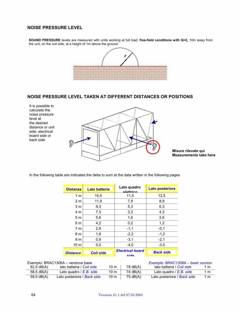
NOISE PRESSURE LEVEL
SOUND PRESSURE levels are measured with units working at full load, free-field conditions with Q=2, 10m away fromthe unit, on the coil side, at a height of 1m above the ground.
NOISE PRESSURE LEVEL TAKEN AT DIFFERENT DISTANCES OR POSITIONS
It is possible to calculate the noise pressure level at the desired distance or unit side: electrical board side or back side
Misure rilevate qui Measurements take here
In the following table are indicated the delta to sum at the data written in the following pages
Distanza Lato batterie Lato quadro
elettrico Lato posteriore
1 m 15,5 11,5 12,5
2 m 11,9 7,9 8,9
3 m 9,3 5,3 6,3
4 m 7,3 3,3 4,3
5 m 5,6 1,6 2,6
6 m 4,2 0,2 1,2
7 m 2,9 -1,1 -0,1
8 m 1,8 -2,2 -1,2
9 m 0,9 -3,1 -2,1
10 m 0,0 -4,0 -3,0
Distance Coil side Electrical board
side Back side
Esempio: BRAC1306A – versione base Example: BRAC1306A – basic version 62,5 dB(A) lato batteria / Coil side 10 m 78 dB(A) lato batteria / Coil side 1 m 58,5 dB(A) Lato quadro / E.B. side 10 m 74 dB(A) Lato quadro / E.B. side 1 m 59,5 dB(A) Lato posteriore / Back side 10 m 75 dB(A) Lato posteriore / Back side 1 m
64 Versione 01.1 del 07.05.2004
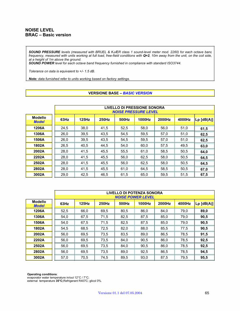
NOISE LEVEL BRAC – Basic version
SOUND PRESSURE levels (measured with BRÜEL & KJǼR class 1 sound-level meter mod. 2260) for each octave bandfrequency, measured with units working at full load, free-field conditions with Q=2, 10m away from the unit, on the coil side,at a height of 1m above the ground. SOUND POWER level for each octave band frequency furnished in compliance with standard ISO3744.
Tolerance on data is equivalent to +/- 1.5 dB.
Note: data furnished refer to units working based on factory settings.
VERSIONE BASE – BASIC VERSION
ModelloModel
LIVELLO DI PRESSIONE SONORA NOISE PRESSURE LEVEL
63Hz 125Hz 250Hz 500Hz 1000Hz 2000Hz 4000Hz Lp [dB(A)]
1206A 24,5 38,0 41,5 52,5 58,0 56,0 51,0 61,5
1306A 26,0 39,5 43,5 54,5 59,5 57,0 51,0 62,5
1506A 26,0 39,5 43,5 54,5 59,5 57,0 51,0 62,5
1802A 26,5 40,5 44,5 54,0 60,0 57,5 49,5 63,0
2002A 28,0 41,5 45,5 55,5 61,0 58,5 50,5 64,0
2202A 28,0 41,5 45,5 56,0 62,5 58,0 50,5 64,5
2502A 28,0 41,5 45,5 56,0 62,5 58,0 50,5 64,5
2802A 28,0 41,5 45,5 61,0 64,5 58,5 50,5 67,0
3002A 29,0 42,5 46,5 61,5 65,0 59,5 51,5 67,5
Modello
LIVELLO DI POTENZA SONORA NOISE POWER LEVEL
Model 63Hz 125Hz 250Hz 500Hz 1000Hz 2000Hz 4000Hz Lp [dB(A)]
1206A 52,5 66,0 69,5 80,5 86,0 84,0 79,0 89,0
1306A 54,0 67,5 71,5 82,5 87,5 85,0 79,0 90,5
1506A 54,0 67,5 71,5 82,5 87,5 85,0 79,0 90,5
1802A 54,5 68,5 72,5 82,0 88,0 85,5 77,5 90,5
2002A 56,0 69,5 73,5 83,5 89,0 86,5 78,5 91,5
2202A 56,0 69,5 73,5 84,0 90,5 86,0 78,5 92,5
2502A 56,0 69,5 73,5 84,0 90,5 86,0 78,5 92,5
2802A 56,0 69,5 73,5 89,0 92,5 86,5 78,5 94,5
3002A 57,0 70,5 74,5 89,5 93,0 87,5 79,5 95,5
Operating conditions: evaporator water temperature in/out 12°C / 7°C; external temperature 35°C;Refrigerant R407C; glicol 0%.
Versione 01.1 del 07.05.2004 65
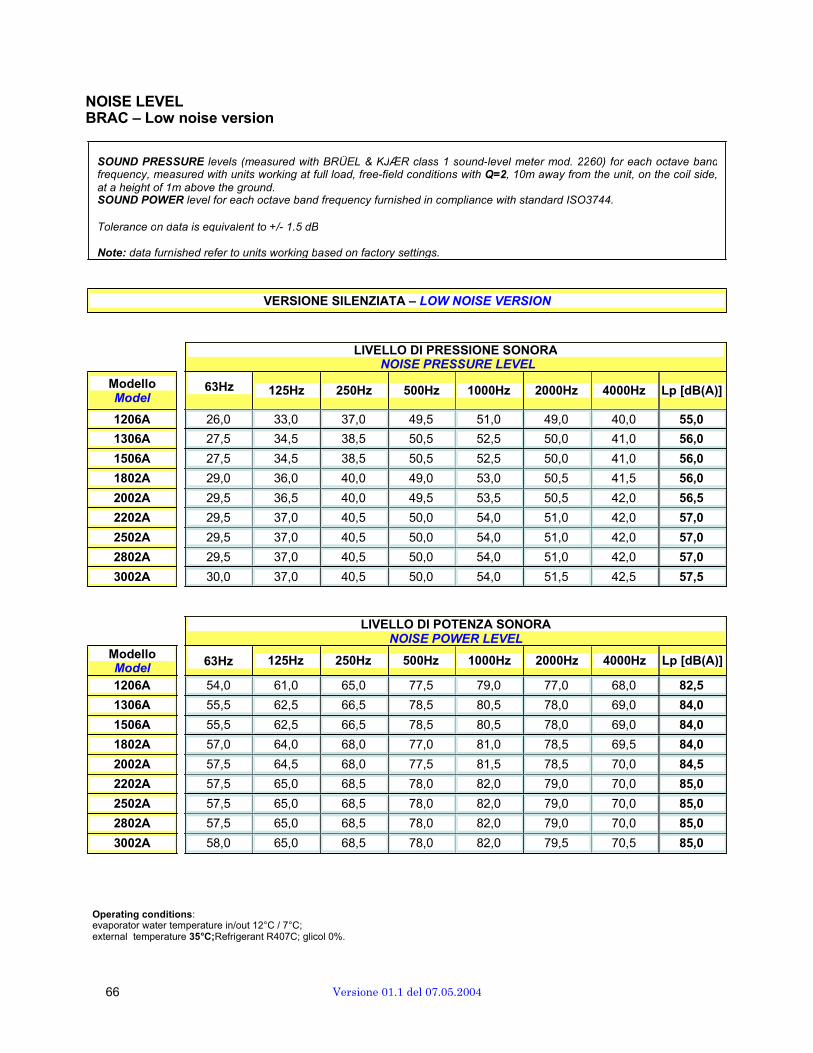
NOISE LEVEL BRAC – Low noise version
SOUND PRESSURE levels (measured with BRÜEL & KJǼR class 1 sound-level meter mod. 2260) for each octave bandfrequency, measured with units working at full load, free-field conditions with Q=2, 10m away from the unit, on the coil side,at a height of 1m above the ground. SOUND POWER level for each octave band frequency furnished in compliance with standard ISO3744.
Tolerance on data is equivalent to +/- 1.5 dB
Note: data furnished refer to units working based on factory settings.
VERSIONE SILENZIATA – LOW NOISE VERSION
ModelloModel
LIVELLO DI PRESSIONE SONORA NOISE PRESSURE LEVEL
63Hz 125Hz 250Hz 500Hz 1000Hz 2000Hz 4000Hz Lp [dB(A)]
1206A 26,0 33,0 37,0 49,5 51,0 49,0 40,0 55,0
1306A 27,5 34,5 38,5 50,5 52,5 50,0 41,0 56,0
1506A 27,5 34,5 38,5 50,5 52,5 50,0 41,0 56,0
1802A 29,0 36,0 40,0 49,0 53,0 50,5 41,5 56,0
2002A 29,5 36,5 40,0 49,5 53,5 50,5 42,0 56,5
2202A 29,5 37,0 40,5 50,0 54,0 51,0 42,0 57,0
2502A 29,5 37,0 40,5 50,0 54,0 51,0 42,0 57,0
2802A 29,5 37,0 40,5 50,0 54,0 51,0 42,0 57,0
3002A 30,0 37,0 40,5 50,0 54,0 51,5 42,5 57,5
Modello
LIVELLO DI POTENZA SONORA NOISE POWER LEVEL
Model 63Hz 125Hz 250Hz 500Hz 1000Hz 2000Hz 4000Hz Lp [dB(A)]
1206A 54,0 61,0 65,0 77,5 79,0 77,0 68,0 82,5
1306A 55,5 62,5 66,5 78,5 80,5 78,0 69,0 84,0
1506A 55,5 62,5 66,5 78,5 80,5 78,0 69,0 84,0
1802A 57,0 64,0 68,0 77,0 81,0 78,5 69,5 84,0
2002A 57,5 64,5 68,0 77,5 81,5 78,5 70,0 84,5
2202A 57,5 65,0 68,5 78,0 82,0 79,0 70,0 85,0
2502A 57,5 65,0 68,5 78,0 82,0 79,0 70,0 85,0
2802A 57,5 65,0 68,5 78,0 82,0 79,0 70,0 85,0
3002A 58,0 65,0 68,5 78,0 82,0 79,5 70,5 85,0
Operating conditions: evaporator water temperature in/out 12°C / 7°C; external temperature 35°C;Refrigerant R407C; glicol 0%.
66 Versione 01.1 del 07.05.2004

NOISE LEVEL BRAT – Basic version
SOUND PRESSURE levels (measured with BRÜEL & KJǼR class 1 sound-level meter mod. 2260) for each octave bandfrequency, measured with units working at full load, free-field conditions with Q=2, 10m away from the unit, on the coil side,at a height of 1m above the ground. SOUND POWER level for each octave band frequency furnished in compliance with standard ISO3744.
Tolerance on data is equivalent to +/- 1.5 dB.
Note: data furnished refer to units working based on factory settings.
VERSIONE BASE – BASIC VERSION
ModelloModel
LIVELLO DI PRESSIONE SONORA NOISE PRESSURE LEVEL
63Hz 125Hz 250Hz 500Hz 1000Hz 2000Hz 4000Hz Lp [dB(A)]
1206A 26,0 39,5 43,5 54,5 59,5 57,0 51,0 62,5
1306A 26,0 39,5 43,5 54,5 59,5 57,0 51,0 62,5
1506A 26,0 39,5 43,5 54,5 59,5 57,0 51,0 62,5
1802A 28,0 41,5 45,5 55,5 61,0 58,5 50,5 64,0
2002A 28,0 41,5 45,5 55,5 61,0 58,5 50,5 64,0
2202A 28,0 41,5 45,5 56,0 62,5 58,0 50,5 64,5
2502A 29,5 43,0 47,0 57,5 64,0 59,5 52,0 66,5
2802A 29,0 42,5 46,5 61,5 65,0 59,5 51,5 67,5
3002A 29,0 42,5 46,5 61,5 65,0 59,5 51,5 67,5
Modello
LIVELLO DI POTENZA SONORA NOISE POWER LEVEL
Model 63Hz 125Hz 250Hz 500Hz 1000Hz 2000Hz 4000Hz Lp [dB(A)]
1206A 54,0 67,5 71,5 82,5 87,5 85,0 79,0 90,5
1306A 54,0 67,5 71,5 82,5 87,5 85,0 79,0 90,5
1506A 54,0 67,5 71,5 82,5 87,5 85,0 79,0 90,5
1802A 56,0 69,5 73,5 83,5 89,0 86,5 78,5 91,5
2002A 56,0 69,5 73,5 83,5 89,0 86,5 78,5 91,5
2202A 56,0 69,5 73,5 84,0 90,5 86,0 78,5 92,5
2502A 57,5 71,0 75,0 85,5 92,0 87,5 80,0 94,0
2802A 57,0 70,5 74,5 89,5 93,0 87,5 79,5 95,5
3002A 57,0 70,5 74,5 89,5 93,0 87,5 79,5 95,5
Operating conditions: evaporator water temperature in/out 12°C / 7°C; external temperature 35°C;Refrigerant R407C; glicol 0%.
Versione 01.1 del 07.05.2004 67

NOISE LEVEL BRAT – Low noise version
SOUND PRESSURE levels (measured with BRÜEL & KJǼR class 1 sound-level meter mod. 2260) for each octave bandfrequency, measured with units working at full load, free-field conditions with Q=2, 10m away from the unit, on the coil side,at a height of 1m above the ground. SOUND POWER level for each octave band frequency furnished in compliance with standard ISO3744.
Tolerance on data is equivalent to +/- 1.5 dB.
Note: data furnished refer to units working based on factory settings.
VERSIONE SILENZIATA – LOW NOISE VERSION
ModelloModel
LIVELLO DI PRESSIONE SONORA NOISE PRESSURE LEVEL
63Hz 125Hz 250Hz 500Hz 1000Hz 2000Hz 4000Hz Lp [dB(A)]
1206A 27,5 34,5 38,5 50,5 52,5 50,0 41,0 56,0
1306A 27,5 34,5 38,5 50,5 52,5 50,0 41,0 56,0
1506A 27,5 34,5 38,5 50,5 52,5 50,0 41,0 56,0
1802A 29,5 36,5 40,0 49,5 53,5 50,5 42,0 56,5
2002A 29,5 36,5 40,0 49,5 53,5 50,5 42,0 56,5
2202A 29,5 37,0 40,5 50,0 54,0 51,0 42,0 57,0
2502A 30,0 37,0 40,5 50,0 54,0 51,5 42,5 57,5
2802A 30,0 37,0 40,5 50,0 54,0 51,5 42,5 57,5
3002A 30,0 37,0 40,5 50,0 54,0 51,5 42,5 57,5
Modello
LIVELLO DI POTENZA SONORA NOISE POWER LEVEL
Model 63Hz 125Hz 250Hz 500Hz 1000Hz 2000Hz 4000Hz Lp [dB(A)]
1206A 55,5 62,5 66,5 78,5 80,5 78,0 69,0 84,0
1306A 55,5 62,5 66,5 78,5 80,5 78,0 69,0 84,0
1506A 55,5 62,5 66,5 78,5 80,5 78,0 69,0 84,0
1802A 57,5 64,5 68,0 77,5 81,5 78,5 70,0 84,5
2002A 57,5 64,5 68,0 77,5 81,5 78,5 70,0 84,5
2202A 57,5 65,0 68,5 78,0 82,0 79,0 70,0 85,0
2502A 58,0 65,0 68,5 78,0 82,0 79,5 70,5 85,0
2802A 58,0 65,0 68,5 78,0 82,0 79,5 70,5 85,0
3002A 58,0 65,0 68,5 78,0 82,0 79,5 70,5 85,0
Operating conditions: evaporator water temperature in/out 12°C / 7°C; external temperature 35°C;Refrigerant R407C; glicol 0%.
68 Versione 01.1 del 07.05.2004
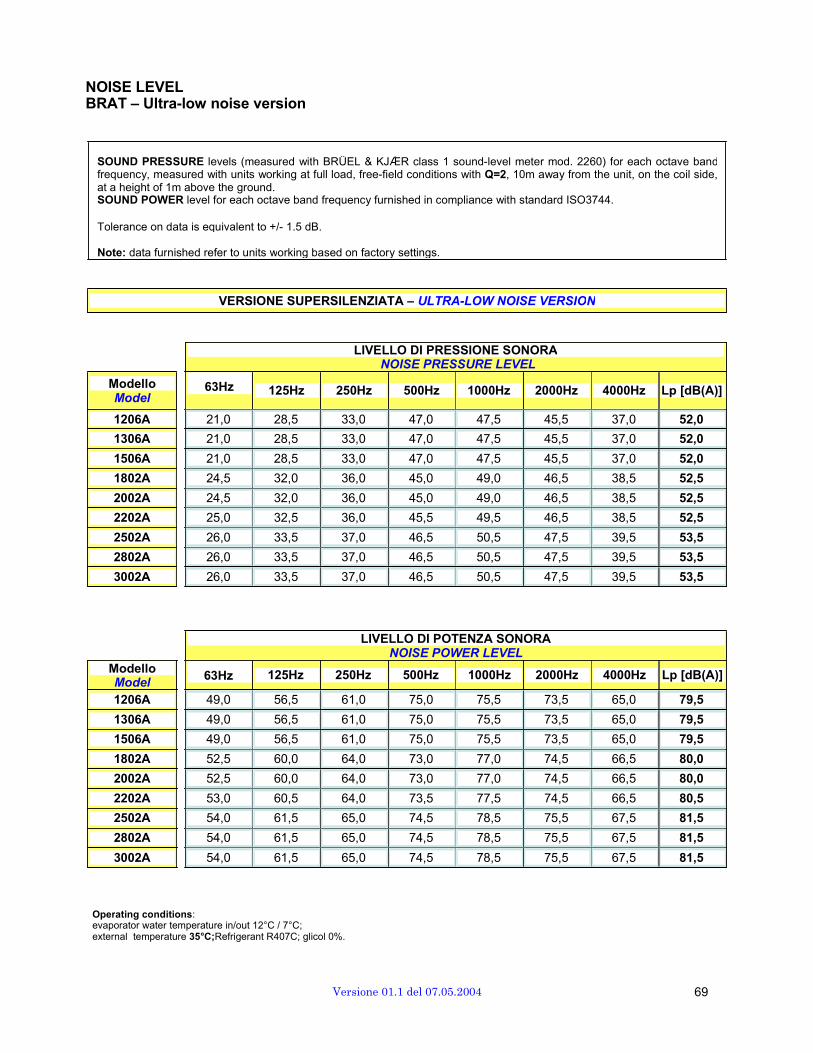
NOISE LEVEL BRAT – Ultra-low noise version
SOUND PRESSURE levels (measured with BRÜEL & KJǼR class 1 sound-level meter mod. 2260) for each octave bandfrequency, measured with units working at full load, free-field conditions with Q=2, 10m away from the unit, on the coil side,at a height of 1m above the ground. SOUND POWER level for each octave band frequency furnished in compliance with standard ISO3744.
Tolerance on data is equivalent to +/- 1.5 dB.
Note: data furnished refer to units working based on factory settings.
VERSIONE SUPERSILENZIATA – ULTRA-LOW NOISE VERSION
ModelloModel
LIVELLO DI PRESSIONE SONORA NOISE PRESSURE LEVEL
63Hz 125Hz 250Hz 500Hz 1000Hz 2000Hz 4000Hz Lp [dB(A)]
1206A 21,0 28,5 33,0 47,0 47,5 45,5 37,0 52,0
1306A 21,0 28,5 33,0 47,0 47,5 45,5 37,0 52,0
1506A 21,0 28,5 33,0 47,0 47,5 45,5 37,0 52,0
1802A 24,5 32,0 36,0 45,0 49,0 46,5 38,5 52,5
2002A 24,5 32,0 36,0 45,0 49,0 46,5 38,5 52,5
2202A 25,0 32,5 36,0 45,5 49,5 46,5 38,5 52,5
2502A 26,0 33,5 37,0 46,5 50,5 47,5 39,5 53,5
2802A 26,0 33,5 37,0 46,5 50,5 47,5 39,5 53,5
3002A 26,0 33,5 37,0 46,5 50,5 47,5 39,5 53,5
Modello
LIVELLO DI POTENZA SONORA NOISE POWER LEVEL
Model 63Hz 125Hz 250Hz 500Hz 1000Hz 2000Hz 4000Hz Lp [dB(A)]
1206A 49,0 56,5 61,0 75,0 75,5 73,5 65,0 79,5
1306A 49,0 56,5 61,0 75,0 75,5 73,5 65,0 79,5
1506A 49,0 56,5 61,0 75,0 75,5 73,5 65,0 79,5
1802A 52,5 60,0 64,0 73,0 77,0 74,5 66,5 80,0
2002A 52,5 60,0 64,0 73,0 77,0 74,5 66,5 80,0
2202A 53,0 60,5 64,0 73,5 77,5 74,5 66,5 80,5
2502A 54,0 61,5 65,0 74,5 78,5 75,5 67,5 81,5
2802A 54,0 61,5 65,0 74,5 78,5 75,5 67,5 81,5
3002A 54,0 61,5 65,0 74,5 78,5 75,5 67,5 81,5
Operating conditions: evaporator water temperature in/out 12°C / 7°C; external temperature 35°C;Refrigerant R407C; glicol 0%.
Versione 01.1 del 07.05.2004 69

NOISE LEVEL BRAF – Basic version
SOUND PRESSURE levels (measured with BRÜEL & KJǼR class 1 sound-level meter mod. 2260) for each octave bandfrequency, measured with units working at full load, free-field conditions with Q=2, 10m away from the unit, on the coil side,at a height of 1m above the ground. SOUND POWER level for each octave band frequency furnished in compliance with standard ISO3744.
Tolerance on data is equivalent to +/- 1.5 dB.
Note: data furnished refer to units working based on factory settings.
VERSIONE BASE – BASIC VERSION
ModelloModel
LIVELLO DI PRESSIONE SONORA NOISE PRESSURE LEVEL
63Hz 125Hz 250Hz 500Hz 1000Hz 2000Hz 4000Hz Lp [dB(A)]
1206A 24,5 38,0 41,5 52,5 58,0 56,0 51,0 61,5
1306A 26,0 39,5 43,5 54,5 59,5 57,0 51,0 62,5
1506A 26,0 39,5 43,5 54,5 59,5 57,0 51,0 62,5
1802A 26,5 40,5 44,5 54,0 60,0 57,5 49,5 63,0
2002A 28,0 41,5 45,5 55,5 61,0 58,5 50,5 64,0
2202A 28,0 41,5 45,5 56,0 62,5 58,0 50,5 64,5
2502A 28,0 41,5 45,5 56,0 62,5 58,0 50,5 64,5
2802A 28,0 41,5 45,5 61,0 64,5 58,5 50,5 67,0
3002A 29,0 42,5 46,5 61,5 65,0 59,5 51,5 67,5
Modello
LIVELLO DI POTENZA SONORA NOISE POWER LEVEL
Model 63Hz 125Hz 250Hz 500Hz 1000Hz 2000Hz 4000Hz Lp [dB(A)]
1206A 52,5 66,0 69,5 80,5 86,0 84,0 79,0 89,0
1306A 54,0 67,5 71,5 82,5 87,5 85,0 79,0 90,5
1506A 54,0 67,5 71,5 82,5 87,5 85,0 79,0 90,5
1802A 54,5 68,5 72,5 82,0 88,0 85,5 77,5 90,5
2002A 56,0 69,5 73,5 83,5 89,0 86,5 78,5 91,5
2202A 56,0 69,5 73,5 84,0 90,5 86,0 78,5 92,5
2502A 56,0 69,5 73,5 84,0 90,5 86,0 78,5 92,5
2802A 56,0 69,5 73,5 89,0 92,5 86,5 78,5 94,5
3002A 57,0 70,5 74,5 89,5 93,0 87,5 79,5 95,5
Operating conditions: evaporator water temperature in/out 12°C / 7°C; external temperature 35°C;Refrigerant R407C; Glicol 20%.
70 Versione 01.1 del 07.05.2004

NOISE LEVEL BRAF – Low noise version
SOUND PRESSURE levels (measured with BRÜEL & KJǼR class 1 sound-level meter mod. 2260) for each octave bandfrequency, measured with units working at full load, free-field conditions with Q=2, 10m away from the unit, on the coil side,at a height of 1m above the ground. SOUND POWER level for each octave band frequency furnished in compliance with standard ISO3744.
Tolerance on data is equivalent to +/- 1.5 dB.
Note: data furnished refer to units working based on factory settings.
VERSIONE SILENZIATA – LOW NOISE VERSION
ModelloModel
LIVELLO DI PRESSIONE SONORA NOISE PRESSURE LEVEL
63Hz 125Hz 250Hz 500Hz 1000Hz 2000Hz 4000Hz Lp [dB(A)]
1206A 26,0 33,0 37,0 49,5 51,0 49,0 40,0 55,0
1306A 27,5 34,5 38,5 50,5 52,5 50,0 41,0 56,0
1506A 27,5 34,5 38,5 50,5 52,5 50,0 41,0 56,0
1802A 29,0 36,0 40,0 49,0 53,0 50,5 41,5 56,0
2002A 29,5 36,5 40,0 49,5 53,5 50,5 42,0 56,5
2202A 29,5 37,0 40,5 50,0 54,0 51,0 42,0 57,0
2502A 29,5 37,0 40,5 50,0 54,0 51,0 42,0 57,0
2802A 29,5 37,0 40,5 50,0 54,0 51,0 42,0 57,0
3002A 30,0 37,0 40,5 50,0 54,0 51,5 42,5 57,5
Modello
LIVELLO DI POTENZA SONORA NOISE POWER LEVEL
Model 63Hz 125Hz 250Hz 500Hz 1000Hz 2000Hz 4000Hz Lp [dB(A)]
1206A 54,0 61,0 65,0 77,5 79,0 77,0 68,0 82,5
1306A 55,5 62,5 66,5 78,5 80,5 78,0 69,0 84,0
1506A 55,5 62,5 66,5 78,5 80,5 78,0 69,0 84,0
1802A 57,0 64,0 68,0 77,0 81,0 78,5 69,5 84,0
2002A 57,5 64,5 68,0 77,5 81,5 78,5 70,0 84,5
2202A 57,5 65,0 68,5 78,0 82,0 79,0 70,0 85,0
2502A 57,5 65,0 68,5 78,0 82,0 79,0 70,0 85,0
2802A 57,5 65,0 68,5 78,0 82,0 79,0 70,0 85,0
3002A 58,0 65,0 68,5 78,0 82,0 79,5 70,5 85,0
Operating conditions: evaporator water temperature in/out 12°C / 7°C; external temperature 35°C;Refrigerant R407C; Glicol 20%.
Versione 01.1 del 07.05.2004 71
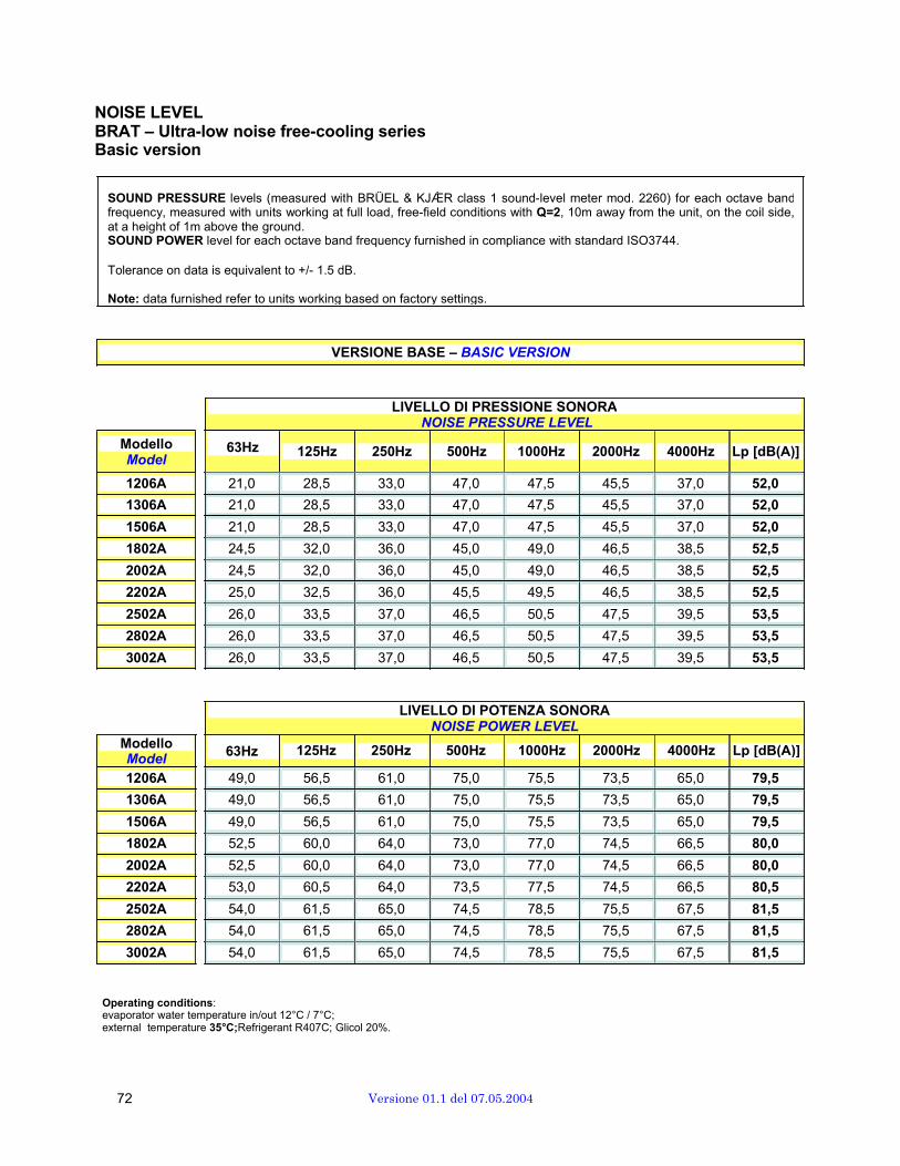
NOISE LEVEL BRAT – Ultra-low noise free-cooling seriesBasic version
SOUND PRESSURE levels (measured with BRÜEL & KJǼR class 1 sound-level meter mod. 2260) for each octave bandfrequency, measured with units working at full load, free-field conditions with Q=2, 10m away from the unit, on the coil side,at a height of 1m above the ground. SOUND POWER level for each octave band frequency furnished in compliance with standard ISO3744.
Tolerance on data is equivalent to +/- 1.5 dB.
Note: data furnished refer to units working based on factory settings.
VERSIONE BASE – BASIC VERSION
ModelloModel
LIVELLO DI PRESSIONE SONORA NOISE PRESSURE LEVEL
63Hz 125Hz 250Hz 500Hz 1000Hz 2000Hz 4000Hz Lp [dB(A)]
1206A 21,0 28,5 33,0 47,0 47,5 45,5 37,0 52,0
1306A 21,0 28,5 33,0 47,0 47,5 45,5 37,0 52,0
1506A 21,0 28,5 33,0 47,0 47,5 45,5 37,0 52,0
1802A 24,5 32,0 36,0 45,0 49,0 46,5 38,5 52,5
2002A 24,5 32,0 36,0 45,0 49,0 46,5 38,5 52,5
2202A 25,0 32,5 36,0 45,5 49,5 46,5 38,5 52,5
2502A 26,0 33,5 37,0 46,5 50,5 47,5 39,5 53,5
2802A 26,0 33,5 37,0 46,5 50,5 47,5 39,5 53,5
3002A 26,0 33,5 37,0 46,5 50,5 47,5 39,5 53,5
Modello
LIVELLO DI POTENZA SONORA NOISE POWER LEVEL
Model 63Hz 125Hz 250Hz 500Hz 1000Hz 2000Hz 4000Hz Lp [dB(A)]
1206A 49,0 56,5 61,0 75,0 75,5 73,5 65,0 79,5
1306A 49,0 56,5 61,0 75,0 75,5 73,5 65,0 79,5
1506A 49,0 56,5 61,0 75,0 75,5 73,5 65,0 79,5
1802A 52,5 60,0 64,0 73,0 77,0 74,5 66,5 80,0
2002A 52,5 60,0 64,0 73,0 77,0 74,5 66,5 80,0
2202A 53,0 60,5 64,0 73,5 77,5 74,5 66,5 80,5
2502A 54,0 61,5 65,0 74,5 78,5 75,5 67,5 81,5
2802A 54,0 61,5 65,0 74,5 78,5 75,5 67,5 81,5
3002A 54,0 61,5 65,0 74,5 78,5 75,5 67,5 81,5
Operating conditions: evaporator water temperature in/out 12°C / 7°C; external temperature 35°C;Refrigerant R407C; Glicol 20%.
72 Versione 01.1 del 07.05.2004
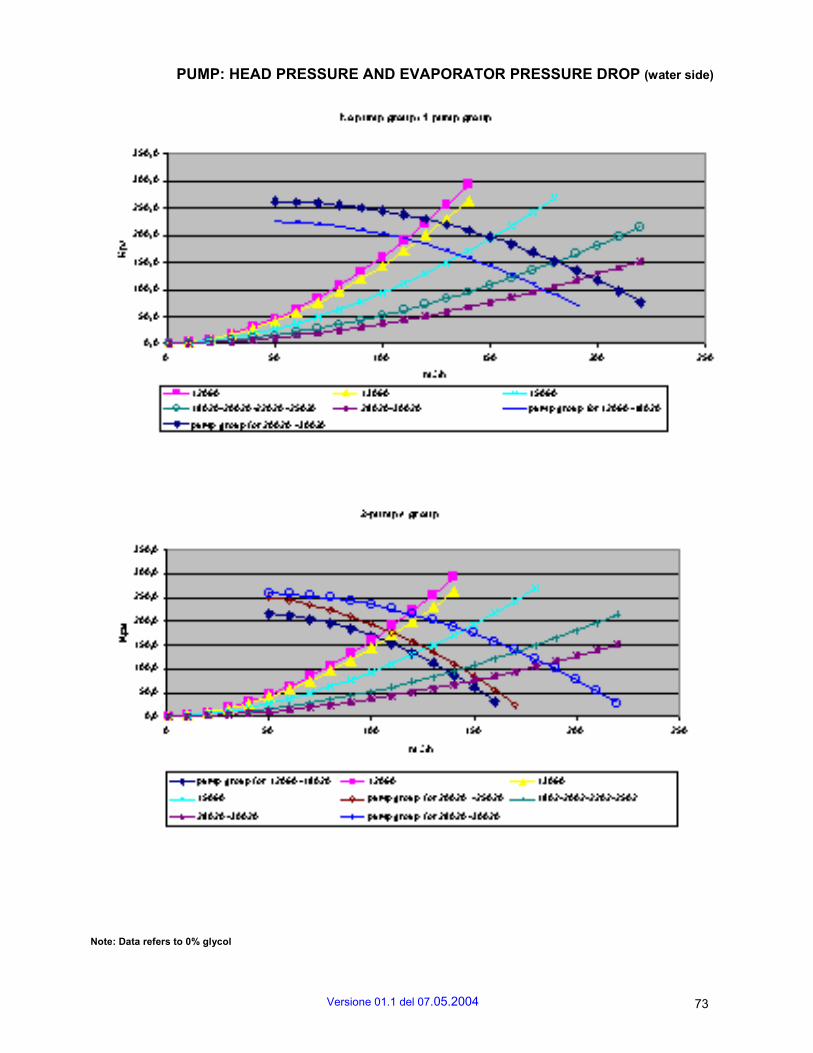
PUMP: HEAD PRESSURE AND EVAPORATOR PRESSURE DROP (water side)
Note: Data refers to 0% glycol
Versione 01.1 del 07.05.2004 73
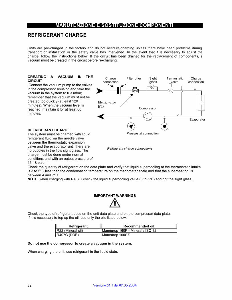
MANUTENZIONE E SOSTITUZIONE COMPONENTI
REFRIGERANT CHARGE
Units are pre-charged in the factory and do not need re-charging unless there have been problems during transport or installation or the safety valve has intervened. In the event that it is necessary to adjust the charge, follow the instructions below. If the circuit has been drained for the replacement of components, a vacuum must be created in the circuit before re-charging.
CREATING A VACUUM IN THE CIRCUIT Connect the vacuum pump to the valves in the compressor housing and take the vacuum in the system to 0.3 mbar; remember that the vacuum must not be created too quickly (at least 120 minutes). When the vacuum level is reached, maintain it for at least 60 minutes.
Charge connection
Eletric valve
ETF
Filter drier Sight glass
Compressor
Termostaticvalve
Charge connection
Evaporator
REFRIGERANT CHARGE The system must be charged with liquid refrigerant fluid via the needle valve between the thermostatic expansion valve and the evaporator until there are no bubbles in the flow sight glass. The charge must be done under normal conditions and with an output pressure of 16-18 bar.
Pressostat connection Refrigerant charge connections
Check the quantity of refrigerant on the data plate and verify that liquid supercooling at the thermostatic intake is 3 to 5°C less than the condensation temperature on the manometer scale and that the superheating is between 4 and 7°C NOTE: when charging with R407C check the liquid supercooling value (3 to 5°C) and not the sight glass.
IMPORTANT WARNINGS
Check the type of refrigerant used on the unit data plate and on the compressor data plate. If it is necessary to top up the oil, use only the oils listed below:
Refrigerant Recommended oil R22 (Mineral oil) Maneurop 160P - Mineral / ISO 32 R407C (POE) Maneurop 160SZ
Do not use the compressor to create a vacuum in the system.
When charging the unit, use refrigerant in the liquid state.
74 Versione 01.1 del 07.05.2004

BLEEDING THE WATER CIRCUIT
If there is air in the water circuit it can be bled using the valves: - on the chilled water intake connection - on the optional reservoir tank During the winter shutdown (cooling-only versions) or for special maintenance, it may be necessary to drain the water circuit. To perform this operation valves have been placed: - on the chilled water outlet connection; - on the bottom of the reservoir tank; Plug for the discharge of water that has accumulated inside the pump (see diagram).
Interception valve for
pump substitution
discharge plug
MAINTENANCE AND CLEANING
All maintenance and cleaning operations must be carried out safely, following the instructions in this manual. To ensure the correct functioning of the unit it is advisable to check regularly that the heat exchanger coils, the metal filters and the protection grilles are clean.
IMPORTANT WARNING
Disconnect the unit from the electric power supply before accessing internal components.
All service and maintenance operations which require access to the internal components of the unit while it is operating must be carried out by qualified experts who are aware of the necessary precautions to take.
Versione 01.1 del 07.05.2004 75
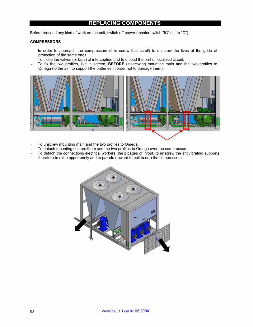
REPLACING COMPONENTS
Before proceed any kind of work on the unit, switch off power (master switch "IG" set to "O").
COMPRESSORS
- In order to approach the compressors (it is screw that scroll) to unscrew the lives of the gride of protection of the same ones.
- To close the valves (or taps) of interception and to unload the part of localized circuit. - To fix the two profiles, like in screen, BEFORE unscrewing mounting main and the two profiles to
Omega (to the aim to support the batteries in order not to damage them).
- To unscrew mounting main and the two profiles to Omega. - To detach mounting centers them and the two profiles to Omega over the compressors. - To detach the connections electrical workers, the pipages of in/out, to unscrew the antivibrating supports
therefore to raise opportunely and to parade (toward to pull to out) the compressors.
98 Versione 01.1 del 07.05.2004

COILS
To get at the coils, shut the shutoff valves (or cocks) and drain the part of the circuit that has been isolated. Disconnect the connecting pipes, unscrew the screws securing the external cover panelling, unscrew the two L-shaped profiles. Unscrew the eight screws fastening the coils (four at the top, four at the bottom) and then pull them out.
PUMPS
To reach the pumps (including optional units), unscrew the screws securing the guards. Shut the shutoff valves (or cocks) and drain the part of the circuit that has been isolated. Disconnect electrical connections, suction/delivery pipes, unscrew supports then lift in the proper manner and pull out.
EVAPORATOR
Versione 01.1 del 07.05.2004 99

( WARNING: use the special brackets supplied with the unit). To reach the evaporator, unscrew the screws securing the guards and unscrew the upright in the middle. Shut the shutoff valves (or cocks) and drain the part of the circuit that has been isolated. Disconnect suction/delivery pipes and release the evaporator from its supports. At this point, pull the evaporator out.
Mod 1206…..1802
Mod. 2002….3002
78 Versione 01.1 del 07.05.2004
SEMI-HERMETIC COMPACT SCREWS
Types: CSH65 • CSH75 • CSH85
Content Page 1 Safety 2 Application ranges 3 Mounting 4 Electrical connection 5 Commissioning 6 Operation / Maintenance 7 De-commissioning
SAFETY
These refrigeration compressors are intended for installation in machines according to the EC Machines Directive 98/37/EC. They may be put to service only, if they have been installed in these machines according to the existing instruction and as a whole agree with the corresponding provisions of legislation (standards to apply: refer to Manufacturers Declaration).*
Authorized staff
All work on compressors and refrigeration systems shall be carried out by qualified and authorized refrigeration personnel only. The compressors are constructed according to the state of the art and valid regulations. Particular emphasis has been placed on the users' safety. Retain these Operating Instructions during the entire lifetime of the compressor.
Residual hazards
Certain residual hazards from the compressors are unavoidable. All persons working on these units must therefore read these Operating Instructions carefully! All of the following have validity: • specific safety regulations and standards (e.g. EN 378, EN 60204 and EN 60355), • generally acknowledged safety standards, • EU directives, • national regulations.
The compressor is under pressure with a holding charge to a pressure of 0.5 to 1 bar above atmospheric pressure. Incorrect handling may cause injury to skin and eyes. Wear safety goggles while working on compressor. Do not open connections before pressure has been released.
Caution! During operation surface temperatures exceeding 60°C or below 0°C can be reached. Serious burns and frostbite are possible. Lock and mark accessible sectors. Before working on the compressor: Switch off and allow to cool down.
Attention! Operate screw compressors only in the prescribed rotating direction! For any work on the compressor after the plant has been commissioned:
Warning! Compressor is under pressure! In case of improper handling severe injuries are possible. Release the pressure in the compressor!
2 APPLICATION RANGER
Versione 01.1 del 07.05.2004 79

Permitted refrigerants
BITZER BSE170 HFKW / HFC R407/C
Application limits see Applications Manual SH-170 and BITZER software
Application limits see brochure SP-170, Applications Manual SH-170 or BITZER software.
For operation in the vacuum range, danger of air admission at the suction side. Special measures might become necessary. In the case of air admission:
Attention! Chemical reactions possible as well as increased condensing pressure and discharge gas temperature.
Warning! In case of air admission a critical shift of the refrigerant ignition limit is possible Absolutely avoid air admission!
3 MOUNTING
3.1 COMPRESSOR TRANSPORT
Transport the compressor either screwed on a pallet or lift it using the eyebolts (see figure 1).
3.2 COMPRESSOR INSTALLATION
Anti-vibration mountings
Use antivibration mountings! Mounting of antivibration mountings: See figure 2. Tighten the screws only until slight deformation of the upper rubber disc is just visible
Fig. 2 Anti-vibration mountings
3.3 PIPE LINE CONNECTIONS
Pipe connections
The pipe connections are designed to accept tubes with standard millimetre or inch dimensions. Solder connections have stepped diameters. According to the size the tube can be pushed more or less into the fitting.
80 Versione 01.1 del 07.05.2004

Attention! Do not overheat the valves! Dismantle pipe connections and bushes for brazing or welding! Cool valves and brazing adaptors even afterwards! Max. brazing temperature 700°C.
Pipe lines
Only use tubes and components which are • clean and dry inside (free from slag, swarf, rust, and phosphate coatings) and • which are delivered with an air tight seal.
Fig. 5 Arrangement of solenoid valves
CAP Cooling capacity CAP Increasing capacity CAP Constant capacity CAP Decreasing capacity CAP 25%* CSH6561/7571/8571: 25% CSH6551/7561/8561: 30% CSH7551/8551: 35% Solenoid valve de-energized Solenoid valve energized Solenoid valve pulsing Solenoid valve intermittent Attention! The application ranges with capacity control are restricted! See SH-170 or BITZER software. Fig. 6 Control sequences
Versione 01.1 del 07.05.2004 81
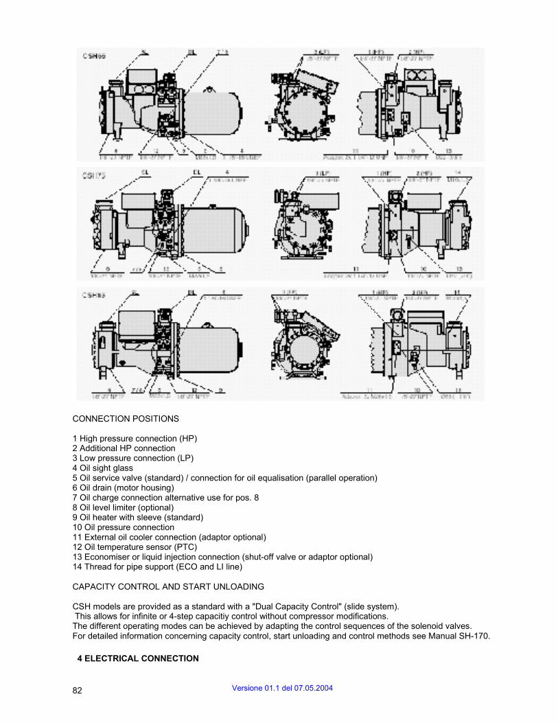
CONNECTION POSITIONS
1 High pressure connection (HP) 2 Additional HP connection 3 Low pressure connection (LP) 4 Oil sight glass 5 Oil service valve (standard) / connection for oil equalisation (parallel operation) 6 Oil drain (motor housing) 7 Oil charge connection alternative use for pos. 8 8 Oil level limiter (optional) 9 Oil heater with sleeve (standard) 10 Oil pressure connection 11 External oil cooler connection (adaptor optional) 12 Oil temperature sensor (PTC) 13 Economiser or liquid injection connection (shut-off valve or adaptor optional) 14 Thread for pipe support (ECO and LI line)
CAPACITY CONTROL AND START UNLOADING
CSH models are provided as a standard with a "Dual Capacity Control" (slide system). This allows for infinite or 4-step capacitiy control without compressor modifications. The different operating modes can be achieved by adapting the control sequences of the solenoid valves. For detailed information concerning capacity control, start unloading and control methods see Manual SH-170.
4 ELECTRICAL CONNECTION
82 Versione 01.1 del 07.05.2004
4.1 GENERAL RECOMMENDATIONS
Compressor and electrical accessories are in accordance with the EC Low Voltage Directive 73/23/EEC (CE 96). The electrical installation is to be carried out according to the wiring diagram in the terminal box and in the Manual SH-170. Observe the safety standards EN 60204, EN 60335 and national safety regulations.
Attention! Danger of severe compressor damage! Cut out holes for cable bushings carefully! Cable bushings must be leakproof to keep condensing water from developing in the terminal box. For the dimensions of the motor con-tactors, cables and fuses:
Attention! Maximum operating current or max. power consumption of the motor should be the base. See name plate or Manual SH-170. Contactor selection: according to operational category AC3. Voltage and frequency data on the name plate should be compared to the electrical supply data. The motor may only be connected when these coincide. Wire the motor terminals according to the indications on the terminal box cover. With part winding motor observe closely part winding order! First part winding (contactor K1): connections 1 / 2 / 3 Second part winding (contactor K2): connections 7 / 8 / 9 Time delay before connection of the second part winding 0.5 sec.
Attention! Danger of motor damage! Wrong wiring results in opposing or displaced rotating fields due to changed phase angle. This leads to locked rotor conditions. Mount connections correctly!
Attention! Danger of insulation damage and motor burn-out! Do not at all repeat the highvoltage test in the same way! However testing with reduced voltage is possible (e. g. 500 V). Among others this restriction is due to the impact of oil and refrigerant on the dielectric strength.
4.2 PROTECTION DEVICES
Motor protection devices Attention!
Break-down of the motor protection device possible! Terminals T1-T2 on the compressor and 3 / 4 / 5 on the terminal strip must not come into contact with the control or supply voltages!
INT69VSY-II is mounted inside the terminal box. The cables for the motor and oil temperature PTC sensors are already connected. D1 must be connected correctly, otherwise there will be no rotation monitoring! Remove bridge D1-L. (Fig. 6). Other connections should be made according to the wiring diagram in the terminal box and in the Manual SH- 170.
Pressure limiters (HP & LP)
Are necessary in order to limit the operating range of the compressor to avoid inadmissible operating condi- tions. For connection positions see page 9. By no means pressure limiters may be connected to the service connection of the shut-off valve! Monitoring the oil circuit Indirect monitoring by means of oil temperature sensor (standard) is only sufficient for short circuits with small system volumes and refrigerant charges. Oil heater ensures the lubricity of the oil even after long standstill periods. It pre-vents increased refrigerant solution in the oil and therefore reduction of viscosity.
Versione 01.1 del 07.05.2004 83
It is mounted in a sleeve and can be replaced if necessary without opening the refrigerating circuit.
The oil heater must be energized during the standstill for: • outdoor installation of the compressor • long shut-off periods • high refrigerant charge • danger of refrigerant condensation into the compressor
Connections according to the wiring diagram.
5 COMMISSIONING
The compressor is already thoroughly dehydrated, tested for leaks and under pressure with holding charge (N 2 ).
Attention! Test the strength pressure and the tightness of the entire plant preferably with dry nitrogen (N 2 ). Compressor must be put out of circuit when using dried air –keep the shut-off valves closed. Danger! By no means the compressor may be pressure tested with oxygen or other industrtial gases!
Warning! Never add refrigerant to the test gas (N 2 or air) – e. g. as leak indicator. Critical shift of the refrigerant ignition limit with high pressure possible! Environmental pollution with leakage or when deflating!
5.2 Tightness test
Evaluate tightness of the entire refrigerant circuit (assembly) or parts of it according to EN 378-2 (or valid equivalent safety standards) by using preferably an overpressure of dry nitrogen at 15 bar.
Danger! Test pressures and safety references see chapter 5.1. For testing the strength pressure or tightness with dry air
Attention! The compressor must not be pressurized with air! Keep the service valves closed. The compressor is already thoroughly dehydrated, tested for leaks and under pressure with holding charge (N 2 ).
5.3 EVACUATION
Energize the oil heater. Open all shut-off valves and solenoid valves. Evacuate the entire system including compressor using a vacuum pump connected to the high and low pressure sides. When the pump is switched off a "standing vacuum" of less than 1.5 mbar must be maintained. If necessary repeat this procedure several times.
Attention! Danger of motor and compressor damage! Do not start compressor under vacuum! Do not apply any voltage – not even for test purposes!
5.4 REFRIGERANT CHARGING
Charge only nitrogen. • Before refrigerant is charged: - Energize the oil heater. - Check the compressor oil level. - Do not switch on the compressor! • Charge liquid refrigerant directly into the condenser resp. receiver. For systems with flooded evaporator refrigerant can be also charged into the evaporator. • After commissioning it may be necessary to add refrigerant:
84 Versione 01.1 del 07.05.2004
Charge the refrigerant from the suction side while the compressor is in operation. Charge preferably at the evaporator inlet. Blends must be taken from the charging cylinder as "solid liquid". If liquid is charged:
Attention! Danger!
Danger of wet operation! Charge small amounts at a time! Keep the discharge temperature at least 30 K (R22, R407C) or at least 20 K (R134a, R404A, R507A) above ondensing tem-perature.
Explosion risk of components and pipelines by hydraulic over-pressure. Avoid absolutely overcharging of the system with refrigerant!
5.5 CHECKS BEFORE STARTING
• Oil level (within sight glass range) • Temperature of the oil separator: at least 15 K above ambient temperature Measuring point: Bottom side of the vessel, approx 10 cm distance from the flange • Setting and function of safety and protection devices • Setting of time relays • Cut-out pressures of the high- and low-pressure limiters • Are the shut-off valves opened? When exchanging a compressor:
Attention! Oil is already in the system. Therefore it may be necessary to drain a part of the oil charge. If there are large quantities of oil in the circuit (possibly from a preceding compressor damage), there is also a risk of liquid slugging at start. Adjust oil level within the sight glass range! Additional measures when replacing a reciprocating compressor:
Attention! Danger of compressor damage! The new oil has a higher viscosity and a strong solvent effect within the refrigerating circuit. • Mount a suction side cleaning filter (filter mesh 25 m).
Attention! Danger of compressor damage! Use a filter with perforated metal tubes around the inside and outside diameter of the filter element – suitable for bidirectional operation. • Replace oil and suction side cleaning filter after a few operating hours. • Repeat this procedure if required. See also chapter 6.2.
5.6 START-UP PROCEDURE
CHECKING THE ROTATING DIRECTION
Attention! Danger of severe compressor damage! Operate screw compressors only in the prescribed rotating direction! In spite of the phase sequence control by the INT69VSY-II protection device a test is recommended.
Phase sequence test with mounted suction shut-off valve: • Connect a gauge to the suction shut-off valve. Close the spindle and then open one turn. • Start the compressor only briefly (approx. 0.5 .. 1 s). • Correct rotating direction: Suction pressure drops immedia-tely. • Wrong rotating direction: Pressure increases or the protection device shuts off. Change over two phases at the terminals of the common supply line.
Phase sequence test without suction shut-off valve: • Close the solenoid valves (evaporator and economiser).
Versione 01.1 del 07.05.2004 85

• Start the compressor only briefly (approx. 0.5 .. 1 s). • Considerably less changes in pres-sure as with choked suction shut-off valve. • Correct rotating direction: Suction pressure drops. • Wrong rotating direction: Pressure remains unchanged, increases or the protection device shuts off. Change over two phases at the terminals of the common supply line.
Start-up Start the compressor again and slowly open the suction shut-off valve.
Lubrication / oil check The compressor lubrication should be checked immediately after starting. • Oil level within sight glass range or slightly below (repeat checks with-in the first hours of operation). • Oil foam can be generated during the starting phase, but should reduce under stable operating conditions. Otherwise this can indicate excessive liquid in the suction gas.
Attention! Danger of wet operation! Discharge temperature must be at least 30 K ( R407C) or at least 20 K (R134a, R404A, R507Aabove condensing temperature. If larger quantities of oil must be added: Setting of the condenser pressure control
Attention! Danger of liquid slugging! Check the oil return. Setting the high and low pressure limiters (HP & LP) Check exactly switch-on and cutout pressures by experiment according to the operating limits.
The condenser pressure must be set so that the minimum pressure difference is reached within 20 s after starting (see application limits in the Manual SH-170 or BITZER software). Rapid reduction in pressure must be avoided by a sensitive pressure control. Checking the operating data • Evaporating temperature • Suction gas temperature • Condensing temperature • Discharge gas temperature - at least 30 K (R22, R407C) or at least 20 K (R134a, R404A, R507A) above condensing temp., - max. 120°C outside the discharge pipe • Oil temperature - at bottom side of oil separator • Switching frequency Prepare data sheet. Application limits see Manual SH-170 or BITZER software.
Attention! Danger of severe compressor damage! The following requirements must be ensured by the control logic: Returning time of the control slide – CR3 (Y3) energized • Maximum cycling rate 6 to 8 starts per hour! • 5 minutes minimum operating time desired! • Switch-over time part winding 0.5 s star delta 1 s
Vibrations The whole plant especially the pipe lines and capillary tubes must be checked for abnormal vibrations. If necessary additional protective measures must be taken.
Attention! Pipe fractures and leakages at compressor and other components of the plant possible! Avoid strong vibrations!
6 OPERATION / MAINTENANCE
6.1 REGULAR CHECKS
Examine regularly the plant according to national regulations. The following points should also be checked: • Operating data (chapter 5.6) • Lubrication / oil check (chapter 5.6)
86 Versione 01.1 del 07.05.2004

• Protection devices and all compressor monitoring parts (see chapters 4.2 and 5.6) • Integrated check valve • Update data protocol.
Internal pressure relief valve
The valve is maintenance free. Repeated opening of the valve due to abnormal operating conditions, however, may result in steady leakage. Consequences are losses in capacity and increased discharge temperature. Check and replace the valve in this case. In the CSH85 models two valves are incorporated. Integrated check valve After shut-off the compressor runs backwards for a short time (until pressure equalisation in the oil separator occurs). When the valve is faulty or dirty the runnig back time will increase. In this case the valve must be replaced.
Warning! Compressor is under pressure! Serious injuries possible. Release the pressure in the compressor! Wear safety goggles! Fitting position: Flange at the discharge gas outlet of the oil separator First remove the discharge shut-off valve. Detailed information see Maintenance Instruction SW-170.
6.2 OIL CHANGE
The oil types listed in chapter 2 are characterised by an especially high degree of stability. If the plant is correctly assembled, or if fine filters are installed on the suction side an oil change is not normally needed. If compressor or motor damage occurs an acid test should be made. When required clean up measures must be made: Mount an acid retaining (bi-directional) suction line gas fil- ter and replace the oil. Purge the plant from the highest point on the discharge side into a recycling cylinder. After a few operating hours it may be necessary to replace filter and oil and to purge the plant again. Replacing the oil: Drain the oil out of the oil separator and compressor motor chamber (see figure 7).
Warning! Compressor is under pressure! Serious injuries possible. Release the pressure in the compressor! Wear safety goggles! Oil types: See chapter 2.
Fig. 7 Oil drain positions
Attention! Ester oils are strongly hygroscopic. Moisture is chemically compounded with these oils. It can-not be, or only insufficiently, removed by evacuation. Handle very carefully! Avoid air admission into the plant and oil can! Dispose of waste oil properly! Chlorinated oil is pollutive waste.
7 DE-COMMISSIONING
7.1 STANDSTILL
Versione 01.1 del 07.05.2004 87
Keep the oil heater switched on until dismantling the compressor! This prevents increased refrigerant solution in the compressor oil.
7.2 DISMANTLING THE COMPRESSOR
For repair work, that makes dismantling necessary, or when decommissioning them: Close the shut-off valves at the compressor. Pump-off the refrigerant. Do not release the refrigerant but dispose it properly!
Warning! Compressor can be under pressure! Severe injuries possible. Wear safety goggles! Open the threaded joints or flanges at the compressor valves. Remove the compressor if necessary with a hoisting tool. Disposing the compressor Drain the oil at the compressor. Dispose of waste oil properly! Chlorinated oil is pollutive waste. Have the compressor repaired or disposed of properly!
88 Versione 01.1 del 07.05.2004

Versione 01.1 del 07.05.2004 89

90 Versione 01.1 del 07.05.2004
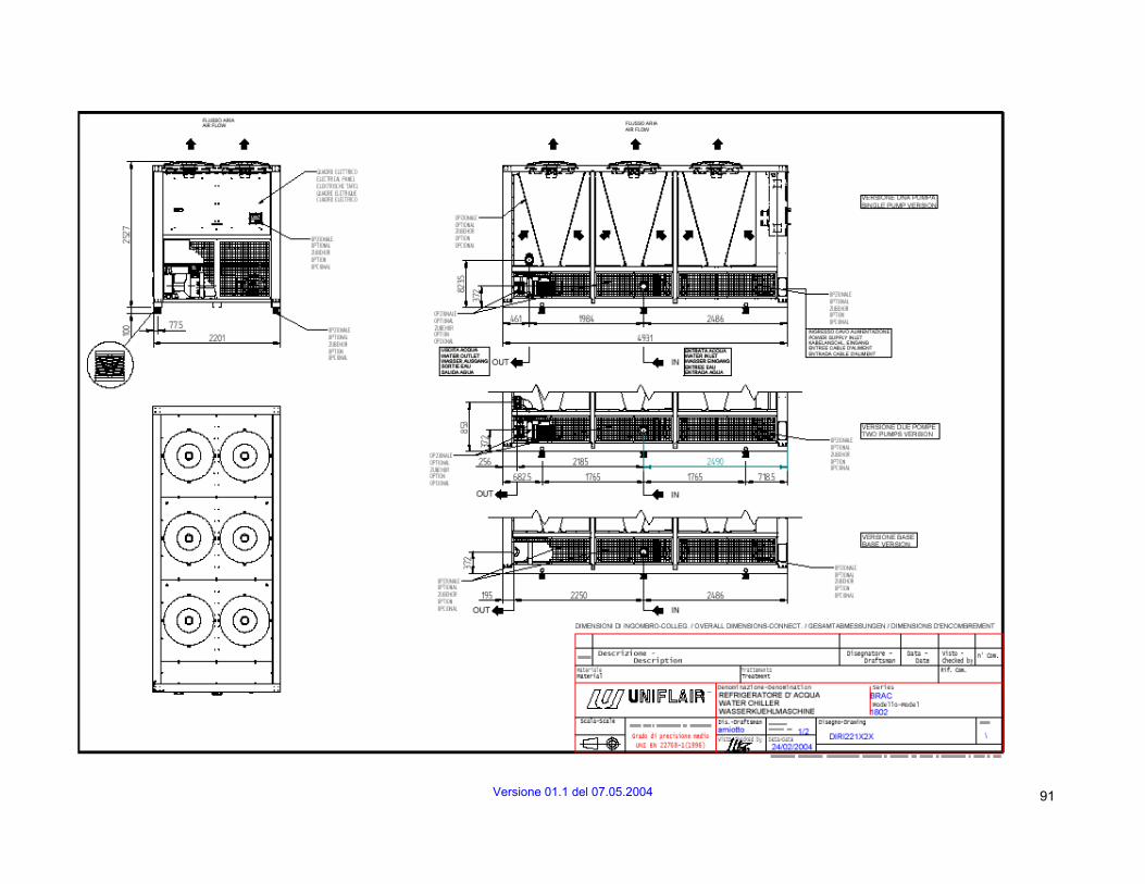
Versione 01.1 del 07.05.2004 91

92 Versione 01.1 del 07.05.2004
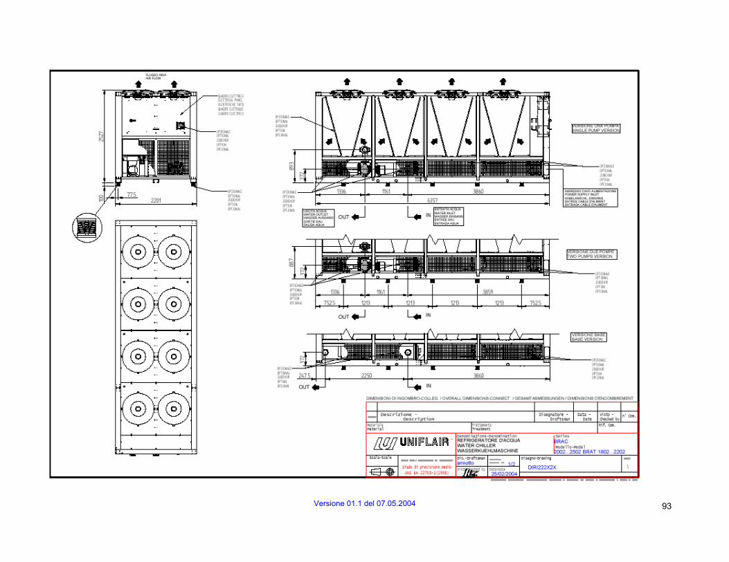
Versione 01.1 del 07.05.2004 93

94 Versione 01.1 del 07.05.2004
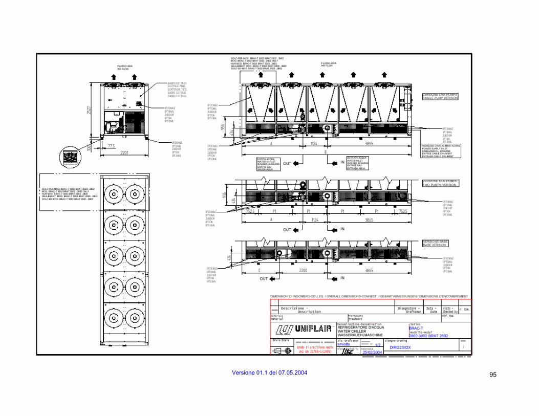
Versione 01.1 del 07.05.2004 95

96 Versione 01.1 del 07.05.2004

Versione 01.1 del 07.05.2004 97
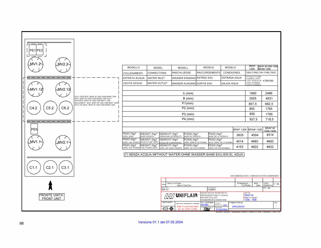
98 Versione 01.1 del 07.05.2004

Versione 01.1 del 07.05.2004 99

100 Versione 01.1 del 07.05.2004
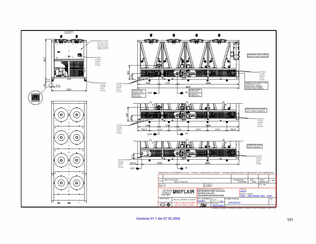
Versione 01.1 del 07.05.2004 101

102 Versione 01.1 del 07.05.2004
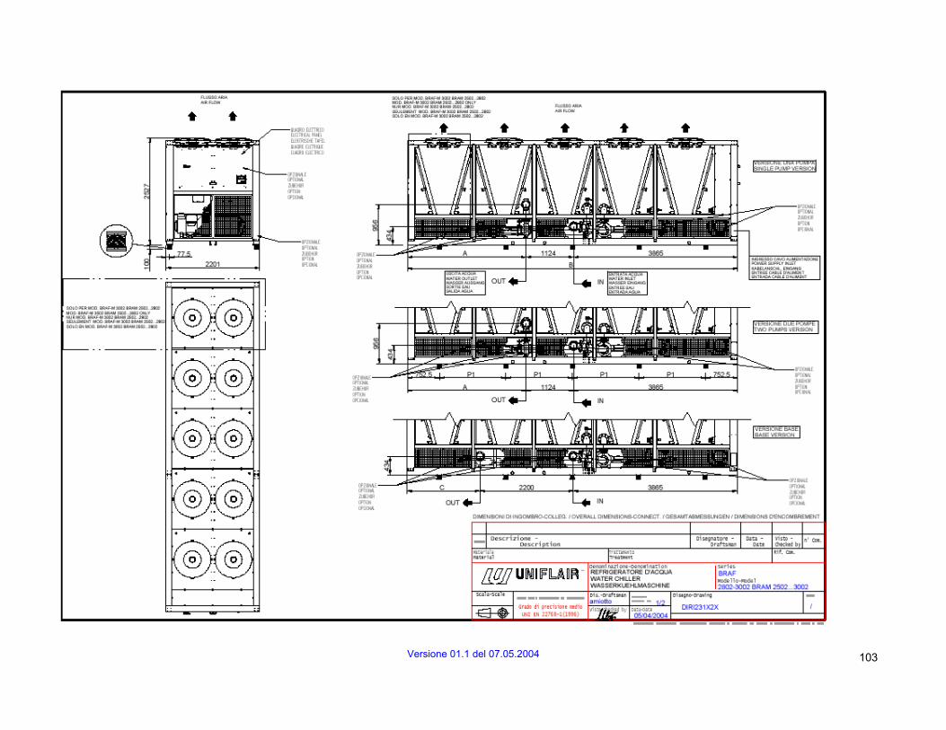
Versione 01.1 del 07.05.2004 103

104 Versione 01.1 del 07.05.2004
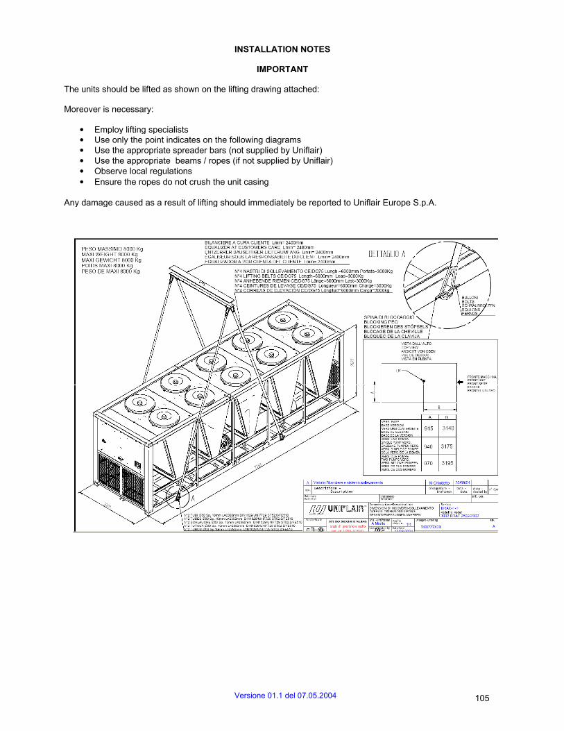
INSTALLATION NOTES
IMPORTANT
The units should be lifted as shown on the lifting drawing attached:
Moreover is necessary:
• Employ lifting specialists • Use only the point indicates on the following diagrams • Use the appropriate spreader bars (not supplied by Uniflair) • Use the appropriate beams / ropes (if not supplied by Uniflair) • Observe local regulations • Ensure the ropes do not crush the unit casing
Any damage caused as a result of lifting should immediately be reported to Uniflair Europe S.p.A.
Versione 01.1 del 07.05.2004 105

106 Versione 01.1 del 07.05.2004

Versione 01.1 del 07.05.2004 107
UNIFLAIR S.p.A. Legal and Aministrative Headquarters: Viale della Tecnica 2, 35026 Conselve (PD) Italy Tel +39 049 5388211 Fax +39 049 5388212 - uniflair.com [email protected] P.IVA 02160760282 C.C.I.A.A. di PD R.E.A. 212586 del 21/04/1988 - R.I.N. 02160760282 M. PD004505 Share capital € 19.550.000
06MM103@00B0110