NECS-CN / NECS-CND - Prime Climate · Codice: B100HL_106_ 1 10D_CV_0 6 _07_IT_GB NECS-CN 0152 -...
30
Codice: B100HL_106_110D_CV_06_07_IT_GB NECS-CN 0152 - 0612 36 - 154 kW Pompe di calore condensate ad aria con ventilatori centrifughi Reverse cycle air/water heat pumps with centrifugal fans Refrigerante Refrigerant Serie Serie Size Range NECS-CN / NECS-CND R410A Unità con 2 compressori, 1 circuito, Compressori Scroll Evaporatore a piastre inox saldobrasate Disponibile in versione con Recupero Parziale Disponibile con Gruppo Idronico Integrato IDRORELAX Network Unit Units with 2 compressor, 1 circuit, Scroll compressors Steel braze-welded plate evaporator Available with Partial Recovery Available with Integrated Hydronic Group IDRORELAX Network Unit 0152 - 0612 36 - 154 kW Sostituisce/Replace: B100HL_106_110D_CV_02_07_IT_GB
Transcript of NECS-CN / NECS-CND - Prime Climate · Codice: B100HL_106_ 1 10D_CV_0 6 _07_IT_GB NECS-CN 0152 -...

Cod
ice:
B10
0HL_
106_
110D
_CV
_06_
07_I
T_G
B
NE
CS
-CN
0
152
- 06
1236
- 1
54 k
W
Pompe di calore condensate ad ariacon ventilatori centrifughi
Reverse cycle air/water heat pumpswith centrifugal fans
RefrigeranteRefrigerant
SerieSerie
SizeRange
NECS-CN / NECS-CND
R410A
Unità con 2 compressori, 1 circuito, Compressori ScrollEvaporatore a piastre inox saldobrasateDisponibile in versione con Recupero ParzialeDisponibile con Gruppo Idronico IntegratoIDRORELAX Network Unit
Units with 2 compressor, 1 circuit, Scroll compressorsSteel braze-welded plate evaporatorAvailable with Partial RecoveryAvailable with Integrated Hydronic GroupIDRORELAX Network Unit
0152 - 061236 - 154 kW
Sos
titui
sce/
Rep
lace
: B10
0HL_
106_
110D
_CV
_02_
07_I
T_G
B

Valori ESEER
Descrizione unità
Accessori
Caratteristiche controllore
Prestazioni ventilatori
Dati tecnici generali
Prestazioni in refrigerazione
Prestazioni in pompa di calore
Prestazioni desurriscaldatore
Limiti di funzionamento
Dati idraulici
Dati elettrici
Livelli sonori a pieno carico
Disegni dimensionali
Gruppo idronico (optional)
pg. n° I
pg. n° 1
pg. n° 3
pg. n° 4
pg. n° 5
pg. n° 7
pg. n° 9
pg. n° 12
pg. n° 15
pg. n° 17
pg. n° 18
pg. n° 19
pg. n° 20
pg. n° A1
pg. n° B1
I dati contenuti possono essere variati senza obbligo di preavvisoAll specification and data are subject to change without notice
ESEER values
Unit description
Accessories
Electronic control features
Fan performances
General technical data
Cooling capacity performance
Heat pump capacity performance
Desuperheater capacity performance
Operating range
Hydraulic data
Electrical data
Full load sound level
Dimensional drawings
Hydronic group (optional)
SOMMARIO SOMMARY
B100HL_106_110D_CV_06_07_IT_GB
NECS-CN 0152 - 0612
Questa azienda è associataal Programma di Certificazione Eurovent.I prodotti sono elencati nelDirectory dei prodotti certificati.
This company partecipatesin the Eurovent Certification Programme.
The products are listed in theDirectory of certified products.
Company quality systemcertified to UNI EN ISO 9001
Azienda con sistema qualitàcertificato UNI EN ISO 9001
I B100HL_106_110D_CV_06_07_IT_GB
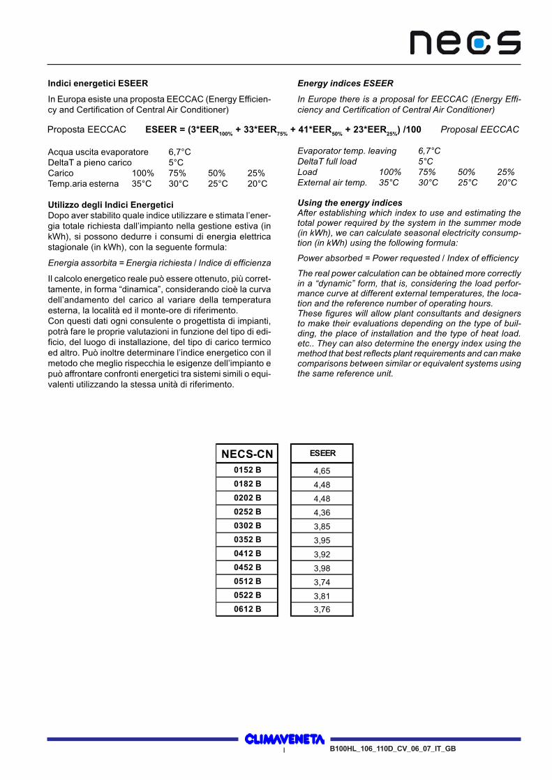
Indici energetici ESEER
In Europa esiste una proposta EECCAC (Energy Efficien-cy and Certification of Central Air Conditioner)
Acqua uscita evaporatore 6,7°CDeltaT a pieno carico 5°CCarico 100% 75% 50% 25%Temp.aria esterna 35°C 30°C 25°C 20°C
Utilizzo degli Indici EnergeticiDopo aver stabilito quale indice utilizzare e stimata l’ener-gia totale richiesta dall’impianto nella gestione estiva (inkWh), si possono dedurre i consumi di energia elettricastagionale (in kWh), con la seguente formula:
Energia assorbita = Energia richiesta / Indice di efficienza
Il calcolo energetico reale può essere ottenuto, più corret-tamente, in forma “dinamica”, considerando cioè la curvadell’andamento del carico al variare della temperaturaesterna, la località ed il monte-ore di riferimento.Con questi dati ogni consulente o progettista di impianti,potrà fare le proprie valutazioni in funzione del tipo di edi-ficio, del luogo di installazione, del tipo di carico termicoed altro. Può inoltre determinare l’indice energetico con ilmetodo che meglio rispecchia le esigenze dell’impianto epuò affrontare confronti energetici tra sistemi simili o equi-valenti utilizzando la stessa unità di riferimento.
Energy indices ESEER
In Europe there is a proposal for EECCAC (Energy Effi-ciency and Certification of Central Air Conditioner)
Evaporator temp. leaving 6,7°CDeltaT full load 5°CLoad 100% 75% 50% 25%External air temp. 35°C 30°C 25°C 20°C
Using the energy indicesAfter establishing which index to use and estimating thetotal power required by the system in the summer mode(in kWh), we can calculate seasonal electricity consump-tion (in kWh) using the following formula:
Power absorbed = Power requested / Index of efficiency
The real power calculation can be obtained more correctlyin a “dynamic” form, that is, considering the load perfor-mance curve at different external temperatures, the loca-tion and the reference number of operating hours.These figures will allow plant consultants and designersto make their evaluations depending on the type of buil-ding, the place of installation and the type of heat load.etc.. They can also determine the energy index using themethod that best reflects plant requirements and can makecomparisons between similar or equivalent systems usingthe same reference unit.
Proposta EECCAC ESEER = (3*EER100% + 33*EER75% + 41*EER50% + 23*EER25%) /100 Proposal EECCAC
NECS-CN ESEER
0152 B 4,65
0182 B 4,48
0202 B 4,48
0252 B 4,36
0302 B 3,85
0352 B 3,95
0412 B 3,92
0452 B 3,98
0512 B 3,74
0522 B 3,81
0612 B 3,76

UNIT DESCRIPTIONNECS-CN
DESCRIZIONE UNITA'
Smart Defrost (Brevetto Climaveneta) Smart Defrost ( Climaveneta Patent)Le pompe di calore sono dotate di un innovativo sistema di sbrinamentoautoadattativo brevettato capace di ottimizzare i tempi di sbrinamentomigliorando l’efficienza totale dell’unità.La forza di questa nuova logica è la capacità di modificare i parametriutilizzati dagli algoritmi ciclo dopo ciclo in modo automatico in funzione dellecondizioni esterne.Tre differenti algoritmi (Timing Defrost, Autotuning Defrost, Free Defrost)controllando la pressione di evaporazione, temperatura aria esterna etempo di sbrinamento permettono un’ottima stima del ghiaccio sulla batteriagarantendo così un efficace ed efficiente ciclo di sbrinamento.
The air to water heat pumps incorporate an innovative auto tuningdefrosting system that is able to optimize the defrosting time withimprovement of the total efficiency.The new logic power is the capacity to modify automatically the parameterscycle by cycle in according to external conditions.Three different algorithms (Timing Defrost, Auto tuning Defrost, FreeDefrost) estimate exactly the quantity of ice inside the coils on the base ofevaporating pressure, defrosting time of the preview cycle and external airtemperature. The new system assure an efficiency and efficacy defrostingcycle.
Pompa di calore aria-acqua Air-to-water heat pumpPompa di calore del tipo aria-acqua ad inversone di ciclo adatta perinstallazione all'interno o in posizione protetta, con ventilatori centrifughi,con commutazione manuale del regime di funzionamento. Unità fornitacompleta di carica olio incongelabile, carica refrigerante, collaudo e prove difunzionamento in fabbrica e necessita quindi, sul luogo dell'installazione,delle sole connessioni idriche ed elettriche.
Reverse cycle air-to-water heat pump for indoor or sheltered installation,with centrifugal fans, with manual mode switch. The unit is supplied withanti-freeze oil and refrigerant and has been factory tested. On-siteinstallation therefore just involves making connections to the mains powerand water supplies.
Unità caricata con refrigerante ecologico R410A Unit charged with R410A ecological refrigerant.
COMPOSIZIONI UNITA' STANDARD STANDARD UNIT COMPOSITION
Struttura Supporting frameStruttura realizzata con basamento in lamiera di acciaio zincato a caldo diadeguato spessore, verniciato con polveri poliesteri e struttura perimetralecomposta da profilati di alluminio.
Frame with base in polyester-painted thick hot-galvanised sheet steel.Shaped aluminium walls.
Pannellatura PanellingPannellatura esterna di contenimento in lamiera prerivestita in similperaluman, di adeguato spessore, realizzata in modo da permettere latotale accessibilità ai componenti interni.
The external panelling, made from simil peraluman, epoxy painted sheetmetal, offers maximum ease of access to the internal components.
Compressori CompressorsCompressori di tipo ermetico rotativo scroll. Tutti i compressori sonocompleti del riscaldatore del carter, protezione termica elettronica conriarmo manuale centralizzato, motore elettrico a due poli.
Hermetic scroll compressors. All the compressors are fitted with an oil sumpheater, electronic overheating protection with centralised manual reset anda two-pole electric motor.
Scambiatore acqua-refrigerante Water-refrigerant heat exchangerScambiatore a piastre saldobrasate in acciaio AISI 316. Gli scambiatorisono esternamente rivestiti con materassino anticondensa in neoprene acelle chiuse. Quando l'unità è in funzione, la protezione contro la mancanzadi flusso è assicurata da un pressostato differenziale lato acqua. L’unità èinoltre predisposta per funzionare, con miscele incongelabili, fino ad unatemperatura in uscita dallo scambiatore di -8°C.
AISI 316 steel braze-welded plate exchanger. The heat exchangers areinsulated with a closed-cell condensation proof lining in neoprene. When theunit is working, it is protected against lack of flow by a differential pressureswitch mounted on the water side. The unit can work with antifreezemixtures at exchanger outlet temperatures as low as -8°C.
Scambiatore refrigerante-aria Refrigerant-air heat exchangerScambiatore a pacco alettato realizzato con tubi in rame e alette in alluminioadeguatamente spaziate in modo da garantire il miglior rendimento nelloscambio termico.
Finned coil exchanger made from copper tubes and aluminium fins. Thealuminium fins are correctly spaced to guarantee optimum heat exchangeefficiency.
Ventilatori centrifughi Centrifugal fansVentilatori a doppia aspirazione, bilanciati staticamente e dinamicamente,ed accoppiati, tramite cinghie e puleggie regolabili, ai relativi motori trifase a4 poli montati su slitte tendicinghie. Mandata aria verticale.
Statically and dynamically balanced, dual inlet fans coupled with adjustablebelts and pulleys to the relative three-phase 4-pole motors mounted on belt-tightening slides. Vertical air delivery.
Circuito frigorifero Refrigerant circuitPrincipali componenti del circuito frigorifero:- filtro deidratore,- indicatore passaggio liquido con segnalazione presenza umidità,- valvola termostatica con equalizzatore esterno,- valvola di sicurezza alta pressione,- pressostati sicurezza alta e bassa pressione,- ricevitore e separatore di liquido- valvola d'inversione di ciclo a 4 vie
Main components of the refrigerant circuit:- dryer filter,- refrigerant line sight glass with humidity indicator,- externally equalised thermostatic valve,- high pressure safety valve,- high and low pressure switches,- liquid receiver and separator,- 4-way reverse cycle valve.
Quadro elettrico di potenza e controllo Electric power and control panelQuadro elettrico di potenza e controllo, costruito in conformità alle normeEN 60204-1/IEC 204-1, completo di :- trasformatore per il circuito di comando,- sezionatore generale bloccoporta,- interruttori magnetotermici per compressori e ventilatori,- morsetti per blocco cumulativo allarmi (BCA),- morsetti per ON/OFF remoto,- quadro elettrico, con doppia porta e guarnizioni,- controllore elettronico.- Cavi numerati circuito comando- Relè consenso comando pompa
Electric power and control panel, built to EN 60204-1/EC 204-1 standards,complete with:- control circuit transformer,- general door lock isolator,- automatic circuit breakers for compressors and fans,- terminals for cumulative alarm block (BCA),- remote ON/OFF terminals,- electric panel with double door and seals,- electronic controller.- Control circuit numbered wires- Pump control consent relay
HFC R410AB100HL_106_110D_CV_06_07_IT_GB1ELCAdoc 20/03/2006
UNIT DESCRIPTIONNECS-CN
DESCRIZIONE UNITA'
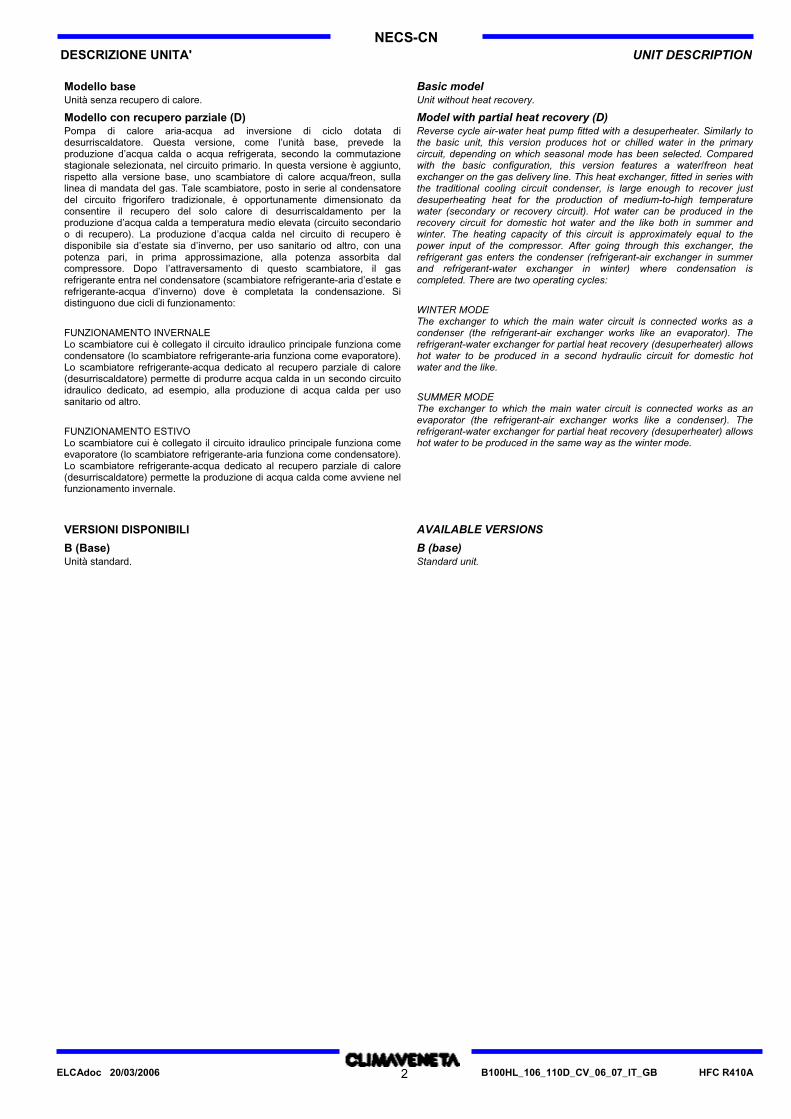
Modello base Basic modelUnità senza recupero di calore. Unit without heat recovery.
Modello con recupero parziale (D) Model with partial heat recovery (D)Pompa di calore aria-acqua ad inversione di ciclo dotata didesurriscaldatore. Questa versione, come l’unità base, prevede laproduzione d’acqua calda o acqua refrigerata, secondo la commutazionestagionale selezionata, nel circuito primario. In questa versione è aggiunto,rispetto alla versione base, uno scambiatore di calore acqua/freon, sullalinea di mandata del gas. Tale scambiatore, posto in serie al condensatoredel circuito frigorifero tradizionale, è opportunamente dimensionato daconsentire il recupero del solo calore di desurriscaldamento per laproduzione d’acqua calda a temperatura medio elevata (circuito secondarioo di recupero). La produzione d’acqua calda nel circuito di recupero èdisponibile sia d’estate sia d’inverno, per uso sanitario od altro, con unapotenza pari, in prima approssimazione, alla potenza assorbita dalcompressore. Dopo l’attraversamento di questo scambiatore, il gasrefrigerante entra nel condensatore (scambiatore refrigerante-aria d’estate erefrigerante-acqua d’inverno) dove è completata la condensazione. Sidistinguono due cicli di funzionamento:
FUNZIONAMENTO INVERNALELo scambiatore cui è collegato il circuito idraulico principale funziona comecondensatore (lo scambiatore refrigerante-aria funziona come evaporatore).Lo scambiatore refrigerante-acqua dedicato al recupero parziale di calore(desurriscaldatore) permette di produrre acqua calda in un secondo circuitoidraulico dedicato, ad esempio, alla produzione di acqua calda per usosanitario od altro.
FUNZIONAMENTO ESTIVOLo scambiatore cui è collegato il circuito idraulico principale funziona comeevaporatore (lo scambiatore refrigerante-aria funziona come condensatore).Lo scambiatore refrigerante-acqua dedicato al recupero parziale di calore(desurriscaldatore) permette la produzione di acqua calda come avviene nelfunzionamento invernale.
Reverse cycle air-water heat pump fitted with a desuperheater. Similarly tothe basic unit, this version produces hot or chilled water in the primarycircuit, depending on which seasonal mode has been selected. Comparedwith the basic configuration, this version features a water/freon heatexchanger on the gas delivery line. This heat exchanger, fitted in series withthe traditional cooling circuit condenser, is large enough to recover justdesuperheating heat for the production of medium-to-high temperaturewater (secondary or recovery circuit). Hot water can be produced in therecovery circuit for domestic hot water and the like both in summer andwinter. The heating capacity of this circuit is approximately equal to thepower input of the compressor. After going through this exchanger, therefrigerant gas enters the condenser (refrigerant-air exchanger in summerand refrigerant-water exchanger in winter) where condensation iscompleted. There are two operating cycles:
WINTER MODEThe exchanger to which the main water circuit is connected works as acondenser (the refrigerant-air exchanger works like an evaporator). Therefrigerant-water exchanger for partial heat recovery (desuperheater) allowshot water to be produced in a second hydraulic circuit for domestic hotwater and the like.
SUMMER MODEThe exchanger to which the main water circuit is connected works as anevaporator (the refrigerant-air exchanger works like a condenser). Therefrigerant-water exchanger for partial heat recovery (desuperheater) allowshot water to be produced in the same way as the winter mode.
VERSIONI DISPONIBILI AVAILABLE VERSIONS
B (Base) B (base)Unità standard. Standard unit.
HFC R410AB100HL_106_110D_CV_06_07_IT_GB2ELCAdoc 20/03/2006
DESCRIZIONE UNITA' UNIT DESCRIPTIONNECS-CN
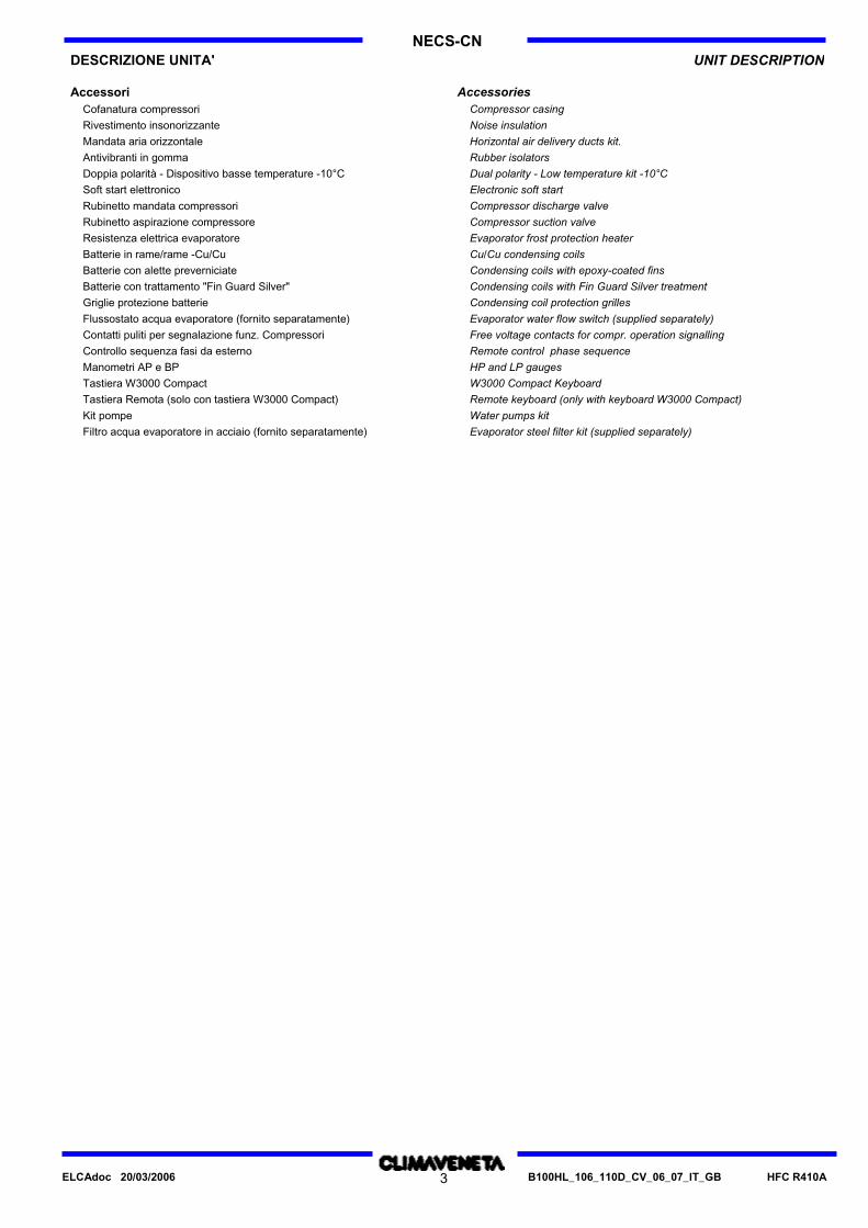
Accessori AccessoriesCofanatura compressori Compressor casingRivestimento insonorizzante Noise insulationMandata aria orizzontale Horizontal air delivery ducts kit.Antivibranti in gomma Rubber isolatorsDoppia polarità - Dispositivo basse temperature -10°C Dual polarity - Low temperature kit -10°CSoft start elettronico Electronic soft startRubinetto mandata compressori Compressor discharge valveRubinetto aspirazione compressore Compressor suction valveResistenza elettrica evaporatore Evaporator frost protection heaterBatterie in rame/rame -Cu/Cu Cu/Cu condensing coilsBatterie con alette preverniciate Condensing coils with epoxy-coated finsBatterie con trattamento "Fin Guard Silver" Condensing coils with Fin Guard Silver treatmentGriglie protezione batterie Condensing coil protection grillesFlussostato acqua evaporatore (fornito separatamente) Evaporator water flow switch (supplied separately)Contatti puliti per segnalazione funz. Compressori Free voltage contacts for compr. operation signallingControllo sequenza fasi da esterno Remote control phase sequenceManometri AP e BP HP and LP gaugesTastiera W3000 Compact W3000 Compact KeyboardTastiera Remota (solo con tastiera W3000 Compact) Remote keyboard (only with keyboard W3000 Compact)Kit pompe Water pumps kitFiltro acqua evaporatore in acciaio (fornito separatamente) Evaporator steel filter kit (supplied separately)
HFC R410AB100HL_106_110D_CV_06_07_IT_GB3ELCAdoc 20/03/2006

NECS-CNDESCRIZIONE UNITA' UNIT DESCRIPTION
Electronic control featuresCaratteristiche controlli elettronici
MicroprocessorMicroprocessore
NECS-CN NECS-CND 0152 - 0612W3000 W3000 Base
Multi-language menuMenù multilingua OPT
Phase sequency relayControllo sequenza fasi OPT
Cumulative fault alarmSegnalazione blocco cumulativo guasti X
Evaporator inlet/outlet water temperature displayVisualizzazione temperatura acqua ingresso/uscita evaporatore X
General unit alarms displayVisualizzazione allarmi generali di macchina X
External air temperature displayVisualizzazione temperatura aria esterna X
Steps inlet water proportional + integral temperature adjustmentRegolazione temperatura ingresso, proporzionale a gradini + integrale X
Steps inlet water proportional temperature adjiustmentRegolazione proporzionale a gradini sulla temperatura in ingresso. X
Quick Mind outlet adjustmentRegolazione Quick Mind in uscita X
Compressors hour rotation + FIFORotazione oraria + FIFO dei compressori X
Starting compressors sequency controlControllo sequenza avviamento compressori X
Ventilation step adjustmentRegolazione a gradini della ventilazione OPT
Demand LimitDemand Limit OPT
Autotuning defrost Smart DefrostSbrinamento autoadattivo Smart Defrost X
Remote keyboardPredisposizione per tastiera remota X
Local/Remote supervision through browser and FWSSupervisione locale/remota mediante browser e FWS OPT
Manager 3000 connectionCollegamento con Manager 3000 OPT
Modbus communication protocolInterfacciabilità con protocollo Modbus OPT
Bacnet communication protocolInterfacciabilità con protocollo Bacnet OPT
Interface connection to LonWorks networkInterfacciabilità con rete LonWorks OPT
Relay manage pumpRelè comando pompa X
Control hydronic kit with 1 pumpGestione gruppo di pompaggio con una pompa OPT
Plant pressure controlControllo impianto in pressione OPT
Remote on/off with external volt-free contactOn/off remoto con contatto esterno privo di tensione X
Summer/winter switching from external contactCommutazione estate/inverno da contatto esterno X
Set-point by 0+10V external contact compensationVariazione set-point da segnale 0-10V esterno OPT
Set-point compensation based on outdoor air temperatureLimitazione del set-point in funzione della temp. aria esterna X
X Fornito di serieOPT Disponibile su richiestapar. Attivabile modificando uno dei valori dei parametri diconfigurazione
X StandardOPT Available on requestpar. Available modifying a value of the configuration parameters
HFC R410AB100HL_106_110D_CV_06_07_IT_GB4ELCAdoc 20/03/2006

5
NECS-CN
B100HL_106_110D_CV_06_07_IT_GB HFC R410A
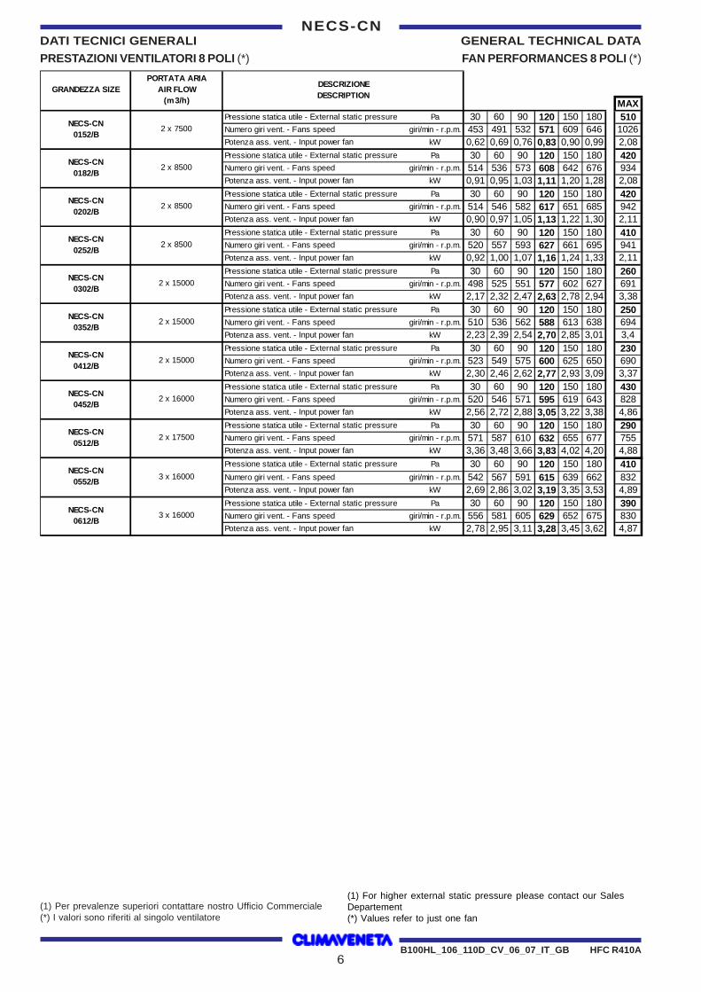
DATI TECNICI GENERALI GENERAL TECHNICAL DATA
PRESTAZIONI VENTILATORI 4 POLI (*) FAN PERFORMANCES 4 POLI (*)
(1) Per prevalenze superiori contattare nostro Ufficio Commerciale(*) I valori sono riferiti al singolo ventilatore
(1) For higher external static pressure please contact our SalesDepartement(*) Values refer to just one fan
MAXPressione statica utile - External static pressure Pa 30 60 90 120 150 180 320Numero giri vent. - Fans speed giri/min - r.p.m. 453 491 532 571 609 646 816Potenza ass. vent. - Input power fan kW 0,62 0,69 0,76 0,83 0,90 0,99 1,41Pressione statica utile - External static pressure Pa 30 60 90 120 150 180 220Numero giri vent. - Fans speed giri/min - r.p.m. 514 536 573 608 642 676 720Potenza ass. vent. - Input power fan kW 0,91 0,95 1,03 1,11 1,20 1,28 1,40Pressione statica utile - External static pressure Pa 30 60 90 120 150 180 210Numero giri vent. - Fans speed giri/min - r.p.m. 514 546 582 617 651 685 718Potenza ass. vent. - Input power fan kW 0,90 0,97 1,05 1,13 1,22 1,30 1,40Pressione statica utile - External static pressure Pa 30 60 90 120 150 180 200Numero giri vent. - Fans speed giri/min - r.p.m. 520 557 593 627 661 695 661Potenza ass. vent. - Input power fan kW 0,92 1,00 1,07 1,16 1,24 1,33 1,39Pressione statica utile - External static pressure Pa 30 60 90 120 150 180 350Numero giri vent. - Fans speed giri/min - r.p.m. 498 525 551 577 602 627 761Potenza ass. vent. - Input power fan kW 2,17 2,32 2,47 2,63 2,78 2,94 3,89Pressione statica utile - External static pressure Pa 30 60 90 120 150 180 340Numero giri vent. - Fans speed giri/min - r.p.m. 510 536 562 588 613 638 763Potenza ass. vent. - Input power fan kW 2,23 2,39 2,54 2,70 2,85 3,01 3,90Pressione statica utile - External static pressure Pa 30 60 90 120 150 180 320Numero giri vent. - Fans speed giri/min - r.p.m. 523 549 575 600 625 650 760Potenza ass. vent. - Input power fan kW 2,30 2,46 2,62 2,77 2,93 3,09 3,88Pressione statica utile - External static pressure Pa 30 60 90 120 150 180 270Numero giri vent. - Fans speed giri/min - r.p.m. 520 546 571 595 619 643 712Potenza ass. vent. - Input power fan kW 2,56 2,72 2,88 3,05 3,22 3,38 3,89Pressione statica utile - External static pressure Pa 30 60 90 120 150 180 370Numero giri vent. - Fans speed giri/min - r.p.m. 571 587 610 632 655 677 809Potenza ass. vent. - Input power fan kW 3,36 3,48 3,66 3,83 4,02 4,20 5,39Pressione statica utile - External static pressure Pa 30 60 90 120 150 180 240Numero giri vent. - Fans speed giri/min - r.p.m. 542 567 591 615 639 662 708Potenza ass. vent. - Input power fan kW 2,69 2,86 3,02 3,19 3,35 3,53 3,87Pressione statica utile - External static pressure Pa 30 60 90 120 150 180 230Numero giri vent. - Fans speed giri/min - r.p.m. 556 581 605 629 652 675 713Potenza ass. vent. - Input power fan kW 2,78 2,95 3,11 3,28 3,45 3,62 3,91
DESCRIZIONEDESCRIPTION
PORTATA ARIAAIR FLOW
(m 3/h)GRANDEZZA SIZE
2 x 8500
NECS-CN 0302/B
2 x 15000
NECS-CN 0352/B
2 x 15000
NECS-CN 0252/B
2 x 15000
NECS-CN 0452/B
2 x 16000
NECS-CN 0512/B
2 x 17500
NECS-CN 0412/B
NECS-CN 0552/B
3 x 16000
NECS-CN 0612/B
3 x 16000
2 x 8500
NECS-CN 0152/B
2 x 7500
NECS-CN 0182/B
2 x 8500
NECS-CN 0202/B
6
NECS-CN
B100HL_106_110D_CV_06_07_IT_GB HFC R410A
DATI TECNICI GENERALI GENERAL TECHNICAL DATA
PRESTAZIONI VENTILATORI 8 POLI (*) FAN PERFORMANCES 8 POLI (*)
(1) Per prevalenze superiori contattare nostro Ufficio Commerciale(*) I valori sono riferiti al singolo ventilatore
(1) For higher external static pressure please contact our SalesDepartement(*) Values refer to just one fan
MAXPressione statica utile - External static pressure Pa 30 60 90 120 150 180 510Numero giri vent. - Fans speed giri/min - r.p.m. 453 491 532 571 609 646 1026Potenza ass. vent. - Input power fan kW 0,62 0,69 0,76 0,83 0,90 0,99 2,08Pressione statica utile - External static pressure Pa 30 60 90 120 150 180 420Numero giri vent. - Fans speed giri/min - r.p.m. 514 536 573 608 642 676 934Potenza ass. vent. - Input power fan kW 0,91 0,95 1,03 1,11 1,20 1,28 2,08Pressione statica utile - External static pressure Pa 30 60 90 120 150 180 420Numero giri vent. - Fans speed giri/min - r.p.m. 514 546 582 617 651 685 942Potenza ass. vent. - Input power fan kW 0,90 0,97 1,05 1,13 1,22 1,30 2,11Pressione statica utile - External static pressure Pa 30 60 90 120 150 180 410Numero giri vent. - Fans speed giri/min - r.p.m. 520 557 593 627 661 695 941Potenza ass. vent. - Input power fan kW 0,92 1,00 1,07 1,16 1,24 1,33 2,11Pressione statica utile - External static pressure Pa 30 60 90 120 150 180 260Numero giri vent. - Fans speed giri/min - r.p.m. 498 525 551 577 602 627 691Potenza ass. vent. - Input power fan kW 2,17 2,32 2,47 2,63 2,78 2,94 3,38Pressione statica utile - External static pressure Pa 30 60 90 120 150 180 250Numero giri vent. - Fans speed giri/min - r.p.m. 510 536 562 588 613 638 694Potenza ass. vent. - Input power fan kW 2,23 2,39 2,54 2,70 2,85 3,01 3,4Pressione statica utile - External static pressure Pa 30 60 90 120 150 180 230Numero giri vent. - Fans speed giri/min - r.p.m. 523 549 575 600 625 650 690Potenza ass. vent. - Input power fan kW 2,30 2,46 2,62 2,77 2,93 3,09 3,37Pressione statica utile - External static pressure Pa 30 60 90 120 150 180 430Numero giri vent. - Fans speed giri/min - r.p.m. 520 546 571 595 619 643 828Potenza ass. vent. - Input power fan kW 2,56 2,72 2,88 3,05 3,22 3,38 4,86Pressione statica utile - External static pressure Pa 30 60 90 120 150 180 290Numero giri vent. - Fans speed giri/min - r.p.m. 571 587 610 632 655 677 755Potenza ass. vent. - Input power fan kW 3,36 3,48 3,66 3,83 4,02 4,20 4,88Pressione statica utile - External static pressure Pa 30 60 90 120 150 180 410Numero giri vent. - Fans speed giri/min - r.p.m. 542 567 591 615 639 662 832Potenza ass. vent. - Input power fan kW 2,69 2,86 3,02 3,19 3,35 3,53 4,89Pressione statica utile - External static pressure Pa 30 60 90 120 150 180 390Numero giri vent. - Fans speed giri/min - r.p.m. 556 581 605 629 652 675 830Potenza ass. vent. - Input power fan kW 2,78 2,95 3,11 3,28 3,45 3,62 4,87
PORTATA ARIAAIR FLOW
(m3/h)
DESCRIZIONEDESCRIPTION
2 x 16000
2 x 8500
NECS-CN 0202/B
2 x 8500
NECS-CN 0452/B
GRANDEZZA SIZE
NECS-CN 0152/B
2 x 7500
NECS-CN 0182/B
2 x 8500
NECS-CN 0252/B
NECS-CN 0302/B
2 x 15000
NECS-CN 0352/B
2 x 15000
NECS-CN 0412/B
2 x 15000
NECS-CN 0612/B
3 x 16000
NECS-CN 0512/B
2 x 17500
NECS-CN 0552/B
3 x 16000

GENERAL TECHNICAL DATABDATI TECNICI GENERALINECS-CN
0152 041203520302025202020182SIZEGRANDEZZA
(1)NECS-CN
kW
kW
Total power input (unit)
Cooling capacity
39 35 15 22 31 20 17 33 30 26 20 18 15 13
49 42 36 95 84 73 55
Potenza assorbita totale (unità)
Potenza frigoriferaPotenza assorbita compressori kWCompressor power input
Portata acqua scambiatorePerdite di carico scambiatore
6 7 8 10 13 14 16 41 47 44 57 32 41 55
Exchanger water flowExchanger water pressure drop
m³/hkPa
Base Base Base Base Base Base BaseElectronicControlControllore Elettronico W3000
Heating capacity 95 82 64 56 48 42 107Potenza termica 32 28 25 20 17 15 13
Total power input (unit) 38 34 30 22 19 17 15Potenza assorbita totale (unità)Exchanger water flow 19 16 14 11 10 8 7Portata acqua scambiatoreExchanger water pressure drop 53 42 72 59 63 72 56Perdite di carico scambiatore
NECS-CNkW
kWm³/hkPa
(2)
Potenza assorbita compressori Compressor power input kW
kWCompressor power inputPotenza assorbita compressori
(1) (5)
kPa
kPam³/h
m³/hkWkW
kW
NECS-CND
Desuperheater water pressure dropDesuperheater water flowEvaporator water pressure dropEvaporator water flowDesuperheater thermal capacityTotal power input (unit)
Cooling capacity
23 18 14 17 13 9 7 5 5 4 3 3 2 2
44 35 61 47 59 44 51 17 15 13 10 8 7 9 30 26 23 18 13 12 16 38 34 30 22 17 14 19 32 29 25 19 14 13 17 98 87 76 57 51 44 38
Perdite di carico desurriscaldatorePortata acqua desurriscaldatorePerdite di carico evaporatorePortata acqua evaporatorePotenza termica al desurriscaldatorePotenza assorbita totale (unità)
Potenza frigorifera
W3000 BaseBaseBaseBaseBaseBaseBaseElectronicControlControllore Elettronico
VentilatoriNumero ventilatoriPortata aria
2 2 2 2 2 2 4,2 4,7 4,7 4,7 8,3 8,3 8,3
2
FansNumber of fansAir flow
nm³/s
STD+OPT
CompressoriNumero compressoriNumero circuitiGradini di capacità (unità)
2 2 2 2 2 2 2 1 1 1 1 1 1 1
2 2 2 22 2 2
CompressorsNumber of compressorsNumber of circuitsCapacity steps (unit)
nnn
CaricaRefrigeranteOlio
28,913,1 13,1 17,8 21,9 19,9 24,9 7 7 7 8 9 9 5
ChargeRefrigerantOil
KgKg
Peso in funzionamento 720 750 790 1080 1170 730 1230Operating weight Kg
Potenza sonora 93 84 86 86 86 93 93Sound power level dB(A)(4)
(1) Acqua evaporatore (in/out) 12/7 °C Aria condensatore (in) 35 °C(2) Acqua condensatore (in/out) 40/45 °C Aria evaporatore (in) 7 °C R.H. 87%(4) Vedi sezione "Livelli sonori a pieno carico"(5) Acqua desurriscaldatore (in/out) 40/45 °C
(1) Chilled water (in/out) 12/7 °C Condenser air (in) 35 °C(2) Condenser water (in/out) 40/45 °C Chilled air (in) 7 °C U.R. 87%(4) See "Full load sound level" section(5) Desuperheater water (in/out) 40/45 °C
HFC R410AB100HL_106_110D_CV_06_07_IT_GB7ELCAdoc 20/03/2006

GENERAL TECHNICAL DATABDATI TECNICI GENERALINECS-CN
0452 061205520512SIZEGRANDEZZA
(1)NECS-CN
kW
kW
Total power input (unit)
Cooling capacity
44 64 58 50 55 48 42 38
137 119 107 154
Potenza assorbita totale (unità)
Potenza frigoriferaPotenza assorbita compressori kWCompressor power input
Portata acqua scambiatorePerdite di carico scambiatore
18 21 24 27 37 45 44 45
Exchanger water flowExchanger water pressure drop
m³/hkPa
Base Base Base BaseElectronicControlControllore Elettronico W3000
Heating capacity 173 153 135 122Potenza termica 52 46 40 36
Total power input (unit) 62 55 47 42Potenza assorbita totale (unità)Exchanger water flow 30 27 24 21Portata acqua scambiatoreExchanger water pressure drop 57 57 60 49Perdite di carico scambiatore
NECS-CNkW
kWm³/hkPa
(2)
Potenza assorbita compressori Compressor power input kW
kWCompressor power inputPotenza assorbita compressori
(1) (5)
kPa
kPam³/h
m³/hkWkW
kW
NECS-CND
Desuperheater water pressure dropDesuperheater water flowEvaporator water pressure dropEvaporator water flowDesuperheater thermal capacityTotal power input (unit)
Cooling capacity
29 23 26 21 8 7 7 6
48 49 39 48 28 21 19 24 49 37 34 43 63 48 43 56 53 40 36 47
160 142 124 111
Perdite di carico desurriscaldatorePortata acqua desurriscaldatorePerdite di carico evaporatorePortata acqua evaporatorePotenza termica al desurriscaldatorePotenza assorbita totale (unità)
Potenza frigorifera
W3000 BaseBaseBaseBaseElectronicControlControllore Elettronico
VentilatoriNumero ventilatoriPortata aria
2 3 3 2 8,9 9,7 13,3 13,3
FansNumber of fansAir flow
nm³/s
STD+OPT
CompressoriNumero compressoriNumero circuitiGradini di capacità (unità)
2 2 2 2 1 1 1 1
22 2 2
CompressorsNumber of compressorsNumber of circuitsCapacity steps (unit)
nnn
CaricaRefrigeranteOlio
45 45 39,7 46,4 14 13 13 12
ChargeRefrigerantOil
KgKg
Peso in funzionamento 1470 1600 1660 1490Operating weight Kg
Potenza sonora 95 97 97 97Sound power level dB(A)(4)
(1) Acqua evaporatore (in/out) 12/7 °C Aria condensatore (in) 35 °C(2) Acqua condensatore (in/out) 40/45 °C Aria evaporatore (in) 7 °C R.H. 87%(4) Vedi sezione "Livelli sonori a pieno carico"(5) Acqua desurriscaldatore (in/out) 40/45 °C
(1) Chilled water (in/out) 12/7 °C Condenser air (in) 35 °C(2) Condenser water (in/out) 40/45 °C Chilled air (in) 7 °C U.R. 87%(4) See "Full load sound level" section(5) Desuperheater water (in/out) 40/45 °C
HFC R410AB100HL_106_110D_CV_06_07_IT_GB8ELCAdoc 20/03/2006

B COOLING CAPACITY PERFORMANCEPRESTAZIONI IN REFRIGERAZIONE NECS-CN
01524225 42 4040 353542403525 3232 3030 253230Ta
6,0Tev 8,07,0Pf 40,2 39,1 37,5 34,5 33,342,639,0 38,0 36,4 33,6 32,441,431,432,635,436,937,940,2Pa 11,9 12,5 13,4 15,0 15,610,611,8 12,4 13,3 14,9 15,510,515,414,813,212,311,710,4Pat 13,5 14,1 15,0 16,6 17,212,213,4 14,0 14,9 16,5 17,112,117,016,414,813,913,312,0Qev 6,9 6,7 6,5 5,9 5,77,36,7 6,5 6,3 5,8 5,67,15,45,66,16,46,56,9Dpev 49,6 47,1 43,2 36,7 34,155,746,8 44,4 40,8 34,6 32,252,630,332,638,441,844,149,6
9,0Tev 11,010,0Pf 43,6 42,4 40,6 37,4 36,046,142,4 41,3 39,6 36,4 35,144,934,235,538,540,241,343,8Pa 12,3 12,8 13,7 15,3 15,910,912,2 12,7 13,6 15,2 15,810,815,715,113,512,612,010,7Pat 13,9 14,4 15,3 16,9 17,512,513,8 14,3 15,2 16,8 17,412,417,316,715,114,213,612,3Qev 7,5 7,3 7,0 6,4 6,27,97,3 7,1 6,8 6,3 6,07,75,96,16,66,97,17,5Dpev 58,4 55,4 50,9 43,0 39,965,555,4 52,6 48,3 40,9 37,962,236,038,845,749,852,558,9
01824225 42 4040 353542403525 3232 3030 253230Ta
6,0Tev 8,07,0Pf 46,3 45,2 43,6 40,8 39,648,945,0 43,9 42,3 39,5 38,447,637,238,341,142,743,846,3Pa 13,6 14,2 15,1 16,7 17,312,213,5 14,0 14,9 16,5 17,212,117,016,314,813,913,312,0Pat 15,8 16,4 17,3 18,9 19,514,415,7 16,2 17,1 18,7 19,414,319,218,517,016,115,514,2Qev 8,0 7,8 7,5 7,0 6,88,47,7 7,6 7,3 6,8 6,68,26,46,67,17,37,58,0Dpev 65,8 62,8 58,3 51,1 48,373,562,3 59,4 55,0 48,0 45,369,742,445,151,956,058,865,9
9,0Tev 11,010,0Pf 50,0 48,9 47,2 44,5 -52,748,8 47,7 46,0 43,2 42,151,540,942,044,846,447,550,2Pa 14,0 14,6 15,5 17,1 -12,613,9 14,5 15,4 17,0 17,612,517,516,815,214,313,812,4Pat 16,2 16,8 17,7 19,3 -14,816,1 16,7 17,6 19,2 19,814,719,719,017,416,516,014,6Qev 8,6 8,4 8,1 7,7 -9,18,4 8,2 7,9 7,5 7,38,97,07,27,78,08,28,6Dpev 76,9 73,6 68,7 60,9 -85,673,1 69,9 65,2 57,6 54,681,551,454,361,766,369,477,5
02024225 42 4040 353542403525 3232 3030 253230Ta
6,0Tev 8,07,0Pf 54,1 52,7 50,5 46,4 44,657,452,6 51,3 49,0 45,1 43,455,842,143,747,649,851,154,3Pa 15,8 16,6 17,7 19,8 20,614,115,7 16,4 17,5 19,6 20,514,020,319,417,416,215,513,8Pat 18,0 18,8 19,9 22,0 22,816,317,9 18,6 19,7 21,8 22,716,222,521,619,618,417,716,0Qev 9,3 9,1 8,7 8,0 7,79,99,1 8,8 8,4 7,8 7,59,67,27,58,28,68,89,3Dpev 57,7 54,7 50,1 42,4 39,264,954,5 51,7 47,3 40,0 37,061,434,837,644,648,751,457,9
9,0Tev 11,010,0Pf 58,6 57,1 54,7 50,3 48,562,157,1 55,6 53,3 49,0 47,260,545,947,751,954,255,659,0Pa 16,3 17,0 18,2 20,2 21,114,616,1 16,9 18,0 20,1 20,914,420,819,917,916,716,014,3Pat 18,5 19,2 20,4 22,4 23,316,818,3 19,1 20,2 22,3 23,116,623,022,120,118,918,216,5Qev 10,1 9,8 9,4 8,7 8,410,79,8 9,6 9,2 8,4 8,110,47,98,28,99,39,610,2Dpev 67,7 64,3 59,0 50,0 46,376,064,3 61,0 56,0 47,4 43,972,241,544,853,057,861,068,5
02524225 42 4040 353542403525 3232 3030 253230Ta
6,0Tev 8,07,0Pf 60,9 59,4 56,9 52,4 50,464,559,2 57,7 55,3 51,0 49,162,747,849,653,856,157,560,9Pa 18,2 18,9 20,2 22,4 23,316,318,0 18,8 20,0 22,3 23,216,223,022,119,918,617,816,0Pat 20,6 21,3 22,6 24,8 25,718,720,4 21,2 22,4 24,7 25,618,625,424,522,321,020,218,4Qev 10,5 10,2 9,8 9,0 8,711,110,2 9,9 9,5 8,8 8,510,88,28,59,39,79,910,5Dpev 53,0 50,3 46,1 39,1 36,359,450,0 47,5 43,6 37,1 34,456,132,635,041,244,847,252,9
9,0Tev 11,010,0Pf 66,0 64,2 61,4 56,4 54,269,964,3 62,6 59,9 55,0 52,968,151,753,758,461,062,666,3Pa 18,6 19,4 20,6 22,8 23,716,718,4 19,2 20,5 22,7 23,616,623,522,520,319,118,316,5Pat 21,0 21,8 23,0 25,2 26,119,120,8 21,6 22,9 25,1 26,019,025,924,922,721,520,718,9Qev 11,4 11,1 10,6 9,7 9,312,011,1 10,8 10,3 9,5 9,111,78,99,310,110,510,811,4Dpev 62,2 58,9 53,9 45,4 41,969,859,0 56,0 51,3 43,3 40,066,338,141,248,753,155,962,8
Ta [°C] - aria esternaTev [°C] - acqua uscente evaporatorePf [kW] - potenza frigoriferaPa [kW] - potenza assorbita compressoriPat [kW] - potenza assorbita totaleQev [m³/h] - portata acqua unitàDpev [kPa] - perdita di carico unità" - " Condizioni fuori dei limiti di funzionamentoNOTA: I dati su fondino si riferiscono ad unità funzionamento non silenziato
Ta [°C] - ambient temperatureTev [°C] - evaporator output water temperaturePf [kW] - cooling capacityPa [kW] - compressor power consumptionPat [kW] - total power input,Qev [m³/h] - evaporator water flowDpev [kPa] - evaporator pressure drop" - " Conditions outside the operating rangeNOTE: Data on grey background: unit switched to non-silencedoperation.
HFC R410AB100HL_106_110D_CV_06_07_IT_GB9ELCAdoc 20/03/2006

B COOLING CAPACITY PERFORMANCEPRESTAZIONI IN REFRIGERAZIONE NECS-CN
03024225 42 4040 353542403525 3232 3030 253230Ta
6,0Tev 8,07,0Pf 80,0 78,1 75,1 69,7 67,484,477,8 76,0 73,0 67,7 65,482,263,465,770,973,875,779,9Pa 23,6 24,6 26,3 29,3 30,621,223,3 24,3 26,0 29,0 30,320,930,028,725,724,123,120,7Pat 28,8 29,8 31,5 34,5 35,826,428,5 29,5 31,2 34,2 35,526,135,233,930,929,328,325,9Qev 13,8 13,4 12,9 12,0 11,614,513,4 13,1 12,6 11,6 11,314,110,911,312,212,713,013,8Dpev 68,3 65,1 60,2 51,9 48,576,164,6 61,6 56,9 48,9 45,672,142,946,053,658,161,168,2
9,0Tev 11,010,0Pf 86,4 84,4 81,3 75,9 -91,084,3 82,3 79,2 73,8 71,588,869,571,777,280,282,186,6Pa 24,2 25,3 27,0 30,0 -21,824,0 25,1 26,7 29,8 31,121,630,929,626,524,823,821,4Pat 29,4 30,5 32,2 35,2 -27,029,2 30,3 31,9 35,0 36,326,836,134,831,730,029,026,6Qev 14,9 14,5 14,0 13,1 -15,714,5 14,2 13,7 12,7 12,315,312,012,413,313,814,114,9Dpev 79,8 76,2 70,7 61,6 -88,675,8 72,4 67,1 58,2 54,684,351,555,063,668,772,080,2
03524225 42 4040 353542403525 3232 3030 253230Ta
6,0Tev 8,07,0Pf 92,2 90,0 86,6 80,5 78,097,589,7 87,5 84,1 78,2 75,794,973,375,881,785,087,192,2Pa 27,0 28,1 29,9 33,2 34,624,426,7 27,8 29,6 32,9 34,324,133,932,529,327,526,423,8Pat 32,4 33,5 35,3 38,6 40,029,832,1 33,2 35,0 38,3 39,729,539,337,934,732,931,829,2Qev 15,9 15,5 14,9 13,9 13,416,815,4 15,1 14,5 13,5 13,016,312,613,014,114,615,015,9Dpev 38,8 37,0 34,2 29,6 27,843,436,7 34,9 32,3 27,9 26,141,124,526,230,433,034,638,8
9,0Tev 11,010,0Pf 99,8 97,5 93,9 87,8 -105,497,3 95,0 91,5 85,4 82,8102,780,482,989,092,594,8100,1Pa 27,8 29,0 30,9 34,2 -25,227,6 28,7 30,6 33,9 35,324,935,033,630,328,427,324,6Pat 33,2 34,4 36,3 39,6 -30,633,0 34,1 36,0 39,3 40,730,340,439,035,733,832,730,0Qev 17,2 16,8 16,2 15,1 -18,216,8 16,4 15,8 14,7 14,317,713,814,315,315,916,317,2Dpev 45,5 43,5 40,4 35,2 -50,843,3 41,2 38,2 33,3 31,348,229,531,436,239,141,045,8
04124225 42 4040 353542403525 3232 3030 253230Ta
6,0Tev 8,07,0Pf 104,1 101,6 97,7 91,0 88,3110,3101,2 98,7 94,9 88,3 85,6107,282,985,692,195,898,3104,2Pa 30,6 31,8 33,8 37,4 38,927,730,2 31,5 33,4 37,0 38,527,438,036,533,031,129,927,1Pat 36,2 37,4 39,4 43,0 44,533,335,8 37,1 39,0 42,6 44,133,043,642,138,636,735,532,7Qev 17,9 17,5 16,8 15,7 15,219,017,4 17,0 16,3 15,2 14,718,514,314,715,916,516,917,9Dpev 49,5 47,1 43,6 37,8 35,655,546,8 44,5 41,1 35,6 33,452,531,433,438,741,944,149,5
9,0Tev 11,010,0Pf 112,9 110,2 106,2 99,3 -119,3109,9 107,3 103,4 96,5 93,7116,391,093,8100,5104,5107,0113,3Pa 31,6 32,9 34,9 38,6 -28,731,3 32,6 34,6 38,2 39,728,439,337,834,232,231,028,1Pat 37,2 38,5 40,5 44,2 -34,336,9 38,2 40,2 43,8 45,334,044,943,439,837,836,633,7Qev 19,4 19,0 18,3 17,1 -20,618,9 18,5 17,8 16,6 16,120,015,716,217,318,018,419,5Dpev 58,2 55,5 51,6 45,1 -65,155,3 52,7 48,8 42,6 40,261,837,840,246,249,952,358,6
04524225 42 4040 353542403525 3232 3030 253230Ta
6,0Tev 8,07,0Pf 117,5 114,6 110,1 102,3 99,0124,5114,3 111,4 107,1 99,4 96,2121,093,496,5104,0108,3111,0117,6Pa 34,4 35,8 38,0 42,0 43,731,234,0 35,4 37,6 41,6 43,330,842,941,237,235,033,730,5Pat 40,6 42,0 44,2 48,2 49,937,440,2 41,6 43,8 47,8 49,537,049,147,443,441,239,936,7Qev 20,2 19,7 19,0 17,6 17,121,419,7 19,2 18,4 17,1 16,620,816,116,617,918,619,120,2Dpev 44,2 42,1 38,8 33,5 31,449,641,8 39,8 36,7 31,6 29,646,927,929,834,637,539,444,3
9,0Tev 11,010,0Pf 127,2 124,1 119,3 111,0 -134,6124,0 120,9 116,2 108,1 -131,2101,8105,2113,2117,8120,7127,9Pa 35,5 36,9 39,2 43,1 -32,235,2 36,6 38,8 42,8 -31,944,142,438,436,234,831,5Pat 41,7 43,1 45,4 49,3 -38,441,4 42,8 45,0 49,0 -38,150,348,644,642,441,037,7Qev 21,9 21,4 20,6 19,1 -23,221,4 20,8 20,0 18,6 -22,617,518,119,520,320,822,0Dpev 51,9 49,4 45,6 39,5 -58,149,3 46,9 43,3 37,4 -55,233,235,441,044,446,752,4
Ta [°C] - aria esternaTev [°C] - acqua uscente evaporatorePf [kW] - potenza frigoriferaPa [kW] - potenza assorbita compressoriPat [kW] - potenza assorbita totaleQev [m³/h] - portata acqua unitàDpev [kPa] - perdita di carico unità" - " Condizioni fuori dei limiti di funzionamentoNOTA: I dati su fondino si riferiscono ad unità funzionamento non silenziato
Ta [°C] - ambient temperatureTev [°C] - evaporator output water temperaturePf [kW] - cooling capacityPa [kW] - compressor power consumptionPat [kW] - total power input,Qev [m³/h] - evaporator water flowDpev [kPa] - evaporator pressure drop" - " Conditions outside the operating rangeNOTE: Data on grey background: unit switched to non-silencedoperation.
HFC R410AB100HL_106_110D_CV_06_07_IT_GB10ELCAdoc 20/03/2006

B COOLING CAPACITY PERFORMANCEPRESTAZIONI IN REFRIGERAZIONE NECS-CN
05124225 42 4040 353542403525 3232 3030 253230Ta
6,0Tev 8,07,0Pf 130,8 127,6 122,5 113,6 109,9138,5127,3 124,1 119,2 110,6 106,9134,8104,0107,5115,9120,7123,7131,0Pa 38,4 39,9 42,3 46,6 48,434,838,0 39,5 41,9 46,2 48,034,447,645,841,539,137,634,0Pat 46,0 47,5 49,9 54,2 56,042,445,6 47,1 49,5 53,8 55,642,055,253,449,146,745,241,6Qev 22,5 22,0 21,1 19,6 18,923,921,9 21,4 20,5 19,0 18,423,217,918,519,920,821,322,5Dpev 54,8 52,1 48,1 41,3 38,761,551,9 49,3 45,5 39,1 36,658,134,637,043,046,649,054,9
9,0Tev 11,010,0Pf 141,4 137,9 132,4 122,7 -149,8137,9 134,5 129,1 119,7 115,7146,0112,8116,6125,8131,0134,4142,3Pa 39,5 41,0 43,4 47,7 -35,939,1 40,7 43,1 47,3 49,135,648,847,042,740,338,835,2Pat 47,1 48,6 51,0 55,3 -43,546,7 48,3 50,7 54,9 56,743,256,454,650,347,946,442,8Qev 24,4 23,8 22,8 21,1 -25,823,8 23,2 22,2 20,6 19,925,219,420,121,722,623,124,5Dpev 64,1 61,0 56,2 48,3 -71,961,0 58,0 53,4 45,9 42,968,440,843,650,755,057,964,9
05524225 42 4040 353542403525 3232 3030 253230Ta
6,0Tev 8,07,0Pf 150,0 146,3 140,6 130,5 126,4158,7145,9 142,3 136,7 127,0 122,9154,4119,5123,4132,9138,3141,8150,0Pa 44,3 46,0 48,8 53,7 55,840,243,8 45,5 48,3 53,2 55,339,754,852,747,845,143,339,3Pat 53,9 55,6 58,4 63,3 65,449,853,4 55,1 57,9 62,8 64,949,364,462,357,454,752,948,9Qev 25,8 25,2 24,2 22,5 21,827,325,1 24,5 23,5 21,9 21,226,620,621,222,923,824,425,8Dpev 54,0 51,4 47,5 40,9 38,360,551,1 48,6 44,9 38,7 36,357,234,336,642,445,948,254,0
9,0Tev 11,010,0Pf 162,2 158,2 152,0 141,1 -171,6158,1 154,2 148,2 137,6 -167,4129,8134,1144,4150,3154,0163,0Pa 45,7 47,4 50,2 55,1 -41,545,2 47,0 49,7 54,7 -41,156,354,249,346,544,740,6Pat 55,3 57,0 59,8 64,7 -51,154,8 56,6 59,3 64,3 -50,765,963,858,956,154,350,2Qev 27,9 27,3 26,2 24,3 -29,627,2 26,6 25,5 23,7 -28,822,423,124,925,926,528,1Dpev 63,2 60,2 55,6 47,9 -70,960,1 57,2 52,8 45,5 -67,340,543,250,154,357,063,9
06124225 42 4040 353542403525 3232 3030 253230Ta
6,0Tev 8,07,0Pf 168,6 164,7 158,5 147,4 142,6177,4163,9 160,2 154,2 143,3 138,7172,6134,8139,3149,8155,6159,3167,7Pa 50,2 52,1 55,1 60,7 63,146,049,7 51,5 54,5 60,1 62,545,561,959,554,051,049,144,9Pat 60,1 62,0 65,0 70,6 73,055,959,6 61,4 64,4 70,0 72,455,471,869,463,960,959,054,8Qev 29,0 28,4 27,3 25,4 24,630,628,2 27,6 26,5 24,7 23,929,723,224,025,826,827,428,9Dpev 53,1 50,7 47,0 40,6 38,058,850,2 47,9 44,4 38,4 35,955,633,936,241,945,247,452,5
9,0Tev 11,010,0Pf 182,3 178,1 171,5 159,4 -191,9177,7 173,7 167,2 155,4 150,4187,1146,5151,4162,9169,2173,2182,3Pa 51,8 53,7 56,8 62,4 -47,651,3 53,2 56,2 61,8 64,347,163,761,355,752,650,846,6Pat 61,7 63,6 66,7 72,3 -57,561,2 63,1 66,1 71,7 74,257,073,671,265,662,560,756,5Qev 31,4 30,7 29,6 27,5 -33,130,6 29,9 28,8 26,8 25,932,225,226,128,129,129,831,4Dpev 62,2 59,4 55,0 47,5 -68,859,1 56,4 52,3 45,2 42,365,440,142,849,653,556,062,1
Ta [°C] - aria esternaTev [°C] - acqua uscente evaporatorePf [kW] - potenza frigoriferaPa [kW] - potenza assorbita compressoriPat [kW] - potenza assorbita totaleQev [m³/h] - portata acqua unitàDpev [kPa] - perdita di carico unità" - " Condizioni fuori dei limiti di funzionamentoNOTA: I dati su fondino si riferiscono ad unità funzionamento non silenziato
Ta [°C] - ambient temperatureTev [°C] - evaporator output water temperaturePf [kW] - cooling capacityPa [kW] - compressor power consumptionPat [kW] - total power input,Qev [m³/h] - evaporator water flowDpev [kPa] - evaporator pressure drop" - " Conditions outside the operating rangeNOTE: Data on grey background: unit switched to non-silencedoperation.
HFC R410AB100HL_106_110D_CV_06_07_IT_GB11ELCAdoc 20/03/2006

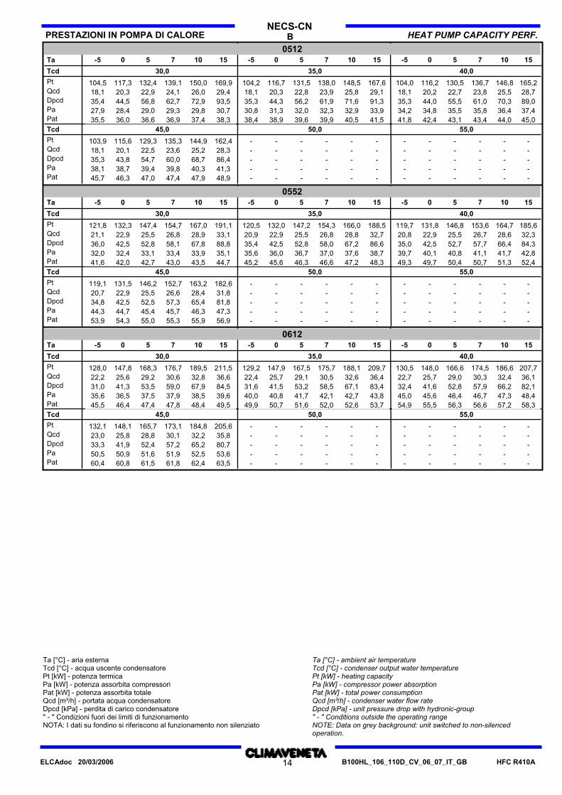
B HEAT PUMP CAPACITY PERF.PRESTAZIONI IN POMPA DI CALORENECS-CN
015215-5 15 1010 7715107-5 55 00 -550Ta
30,0Tcd 40,035,0
Pt 35,9 40,7 42,8 46,1 52,031,736,1 41,1 43,3 46,6 52,731,653,147,143,741,536,331,5Qcd 6,2 7,1 7,4 8,0 9,05,56,3 7,1 7,5 8,1 9,15,59,28,27,67,26,35,5Dpcd 40,4 52,0 57,4 66,6 84,831,440,7 52,7 58,4 67,8 86,531,287,869,059,453,541,030,8Pa 11,5 11,6 11,7 11,9 12,111,410,2 10,3 10,4 10,5 10,810,19,69,39,29,29,09,0Pat 13,1 13,2 13,3 13,5 13,713,011,8 11,9 12,0 12,1 12,411,711,210,910,810,810,610,6
45,0Tcd 55,050,0
Pt - - - - --- - - - --51,345,542,440,435,831,7Qcd - - - - --- - - - --8,97,97,47,06,25,5Dpcd - - - - --- - - - --82,665,256,451,240,231,7Pa - - - - --- - - - --13,613,313,213,113,012,9Pat - - - - --- - - - --15,214,914,814,714,614,5
018215-5 15 1010 7715107-5 55 00 -550Ta
30,0Tcd 40,035,0
Pt 40,8 46,2 48,5 52,1 58,535,940,9 46,5 48,8 52,6 59,235,859,953,049,246,740,935,8Qcd 7,1 8,0 8,4 9,0 10,26,27,1 8,1 8,5 9,1 10,36,210,49,28,58,17,16,2Dpcd 52,1 66,8 73,6 84,9 107,240,452,1 67,4 74,5 86,3 109,540,0111,887,575,267,852,139,8Pa 12,8 12,9 13,0 13,1 13,412,711,3 11,5 11,6 11,8 12,111,210,810,510,310,210,09,9Pat 15,0 15,1 15,2 15,3 15,614,913,5 13,7 13,8 14,0 14,313,413,012,712,512,412,212,1
45,0Tcd 55,050,0
Pt - - - - --- - - - --57,851,548,045,840,736,1Qcd - - - - --- - - - --10,19,08,48,07,16,3Dpcd - - - - --- - - - --104,983,472,566,052,040,9Pa - - - - --- - - - --14,914,614,614,514,514,5Pat - - - - --- - - - --17,116,816,816,716,716,7
020215-5 15 1010 7715107-5 55 00 -550Ta
30,0Tcd 40,035,0
Pt 48,1 54,1 56,8 61,0 68,742,848,4 54,6 57,4 61,8 69,843,270,862,457,955,148,843,6Qcd 8,4 9,4 9,9 10,6 11,97,48,4 9,5 10,0 10,7 12,17,512,310,810,09,58,57,6Dpcd 46,4 58,8 64,7 74,7 94,636,846,9 59,7 65,8 76,3 97,537,299,977,566,760,447,537,9Pa 15,0 15,2 15,3 15,4 15,714,913,3 13,5 13,6 13,7 14,113,212,512,212,011,911,811,7Pat 17,2 17,4 17,5 17,6 17,917,115,5 15,7 15,8 15,9 16,315,414,714,414,214,114,013,9
45,0Tcd 55,050,0
Pt - - - - --- - - - --67,360,156,153,647,742,6Qcd - - - - --- - - - --11,710,59,89,38,37,4Dpcd - - - - --- - - - --91,372,763,457,845,936,5Pa - - - - --- - - - --17,617,317,217,116,916,8Pat - - - - --- - - - --19,819,519,419,319,119,0
025215-5 15 1010 7715107-5 55 00 -550Ta
30,0Tcd 40,035,0
Pt 54,7 61,4 64,4 69,1 77,848,955,1 62,0 65,1 69,9 78,949,379,770,665,762,655,749,9Qcd 9,5 10,7 11,2 12,0 13,58,59,6 10,8 11,3 12,1 13,78,613,812,211,410,99,78,6Dpcd 43,4 54,8 60,2 69,4 87,934,744,0 55,7 61,3 70,8 90,035,291,672,062,356,644,835,9Pa 17,3 17,5 17,6 17,8 18,117,215,4 15,6 15,8 15,9 16,315,314,614,314,114,013,813,7Pat 19,7 19,9 20,0 20,2 20,519,617,8 18,0 18,2 18,3 18,717,717,016,716,516,416,216,1
45,0Tcd 55,050,0
Pt - - - - --- - - - --76,568,363,760,954,348,5Qcd - - - - --- - - - --13,311,911,110,69,58,4Dpcd - - - - --- - - - --85,267,959,254,043,034,3Pa - - - - --- - - - --20,119,819,719,619,419,3Pat - - - - --- - - - --22,522,222,122,021,821,7
Ta [°C] - aria esternaTcd [°C] - acqua uscente condensatorePt [kW] - potenza termicaPa [kW] - potenza assorbita compressoriPat [kW] - potenza assorbita totaleQcd [m³/h] - portata acqua condensatoreDpcd [kPa] - perdita di carico condensatore" - " Condizioni fuori dei limiti di funzionamentoNOTA: I dati su fondino si riferiscono al funzionamento non silenziato
Ta [°C] - ambient air temperatureTcd [°C] - condenser output water temperaturePt [kW] - heating capacityPa [kW] - compressor power absorptionPat [kW] - total power consumptionQcd [m³/h] - condenser water flow rateDpcd [kPa] - unit pressure drop with hydronic-group" - " Conditions outside the operating rangeNOTE: Data on grey background: unit switched to non-silencedoperation.
HFC R410AB100HL_106_110D_CV_06_07_IT_GB12ELCAdoc 20/03/2006

B HEAT PUMP CAPACITY PERF.PRESTAZIONI IN POMPA DI CALORENECS-CN
030215-5 15 1010 7715107-5 55 00 -550Ta
30,0Tcd 40,035,0
Pt 70,1 78,4 82,1 87,9 98,663,070,2 78,6 82,3 88,3 99,663,4100,488,682,378,570,464,0Qcd 12,2 13,6 14,3 15,3 17,110,912,2 13,6 14,3 15,3 17,311,017,415,314,313,612,211,1Dpcd 53,4 66,8 73,2 84,0 105,743,153,4 66,9 73,4 84,6 107,543,5108,984,773,266,653,544,3Pa 21,5 21,9 22,1 22,4 23,021,219,4 19,7 19,8 20,1 20,619,218,518,017,817,717,517,5Pat 26,7 27,1 27,3 27,6 28,226,424,6 24,9 25,0 25,3 25,824,423,723,223,022,922,722,7
45,0Tcd 55,050,0
Pt - - - - --- - - - --97,587,381,678,170,062,9Qcd - - - - --- - - - --17,015,214,213,612,210,9Dpcd - - - - --- - - - --103,783,172,766,553,443,1Pa - - - - --- - - - --25,625,024,624,423,823,3Pat - - - - --- - - - --30,830,229,829,629,028,5
035215-5 15 1010 7715107-5 55 00 -550Ta
30,0Tcd 40,035,0
Pt 81,1 90,9 95,3 102,3 115,172,781,4 91,4 95,9 103,2 116,873,3118,5104,096,491,982,074,5Qcd 14,1 15,8 16,6 17,8 20,012,614,1 15,9 16,6 17,9 20,312,720,518,016,715,914,212,9Dpcd 30,6 38,5 42,2 48,7 61,624,530,7 38,7 42,6 49,4 63,324,964,950,043,039,031,125,6Pa 24,7 25,2 25,4 25,8 26,624,322,2 22,7 22,9 23,3 24,021,921,721,020,720,520,119,9Pat 30,1 30,6 30,8 31,2 32,029,727,6 28,1 28,3 28,7 29,427,327,126,426,125,925,525,3
45,0Tcd 55,050,0
Pt - - - - --- - - - --113,3101,294,690,480,972,6Qcd - - - - --- - - - --19,717,616,515,714,112,6Dpcd - - - - --- - - - --59,947,841,838,230,524,6Pa - - - - --- - - - --29,528,728,328,127,527,0Pat - - - - --- - - - --34,934,133,733,532,932,4
041215-5 15 1010 7715107-5 55 00 -550Ta
30,0Tcd 40,035,0
Pt 90,7 102,7 107,7 115,6 129,579,791,1 103,5 108,8 116,9 131,279,5132,9118,2109,8104,591,880,2Qcd 15,8 17,8 18,7 20,1 22,513,915,8 18,0 18,9 20,3 22,813,823,020,519,018,115,913,9Dpcd 38,3 49,0 54,0 62,2 78,029,538,4 49,7 54,8 63,3 79,829,381,664,555,750,438,929,7Pa 27,8 28,5 28,8 29,2 30,127,225,0 25,7 26,0 26,4 27,224,524,724,023,623,322,722,2Pat 33,4 34,1 34,4 34,8 35,732,830,6 31,3 31,6 32,0 32,830,130,329,629,228,928,327,8
45,0Tcd 55,050,0
Pt - - - - --- - - - --128,0114,3106,7101,990,780,8Qcd - - - - --- - - - --22,319,918,617,715,814,1Dpcd - - - - --- - - - --76,561,053,248,538,430,4Pa - - - - --- - - - --33,432,532,031,731,130,6Pat - - - - --- - - - --39,038,137,637,336,736,2
045215-5 15 1010 7715107-5 55 00 -550Ta
30,0Tcd 40,035,0
Pt 104,8 117,9 123,8 133,1 150,493,6105,4 119,1 125,2 135,0 153,093,9155,5136,8126,7120,4106,394,5Qcd 18,2 20,5 21,5 23,1 26,116,318,3 20,7 21,7 23,4 26,516,326,923,721,920,918,416,4Dpcd 35,8 45,4 50,0 57,8 73,728,636,1 46,1 51,0 59,2 76,128,678,360,652,047,036,628,9Pa 31,4 32,1 32,4 32,9 33,930,828,3 29,0 29,3 29,8 30,827,727,927,026,626,325,625,1Pat 37,6 38,3 38,6 39,1 40,137,034,5 35,2 35,5 36,0 37,033,934,133,232,832,531,831,3
45,0Tcd 55,050,0
Pt - - - - --- - - - --147,6131,2122,3116,8104,393,8Qcd - - - - --- - - - --25,722,821,320,318,216,3Dpcd - - - - --- - - - --71,356,449,044,635,628,8Pa - - - - --- - - - --37,536,536,035,735,034,4Pat - - - - --- - - - --43,742,742,241,941,240,6
Ta [°C] - aria esternaTcd [°C] - acqua uscente condensatorePt [kW] - potenza termicaPa [kW] - potenza assorbita compressoriPat [kW] - potenza assorbita totaleQcd [m³/h] - portata acqua condensatoreDpcd [kPa] - perdita di carico condensatore" - " Condizioni fuori dei limiti di funzionamentoNOTA: I dati su fondino si riferiscono al funzionamento non silenziato
Ta [°C] - ambient air temperatureTcd [°C] - condenser output water temperaturePt [kW] - heating capacityPa [kW] - compressor power absorptionPat [kW] - total power consumptionQcd [m³/h] - condenser water flow rateDpcd [kPa] - unit pressure drop with hydronic-group" - " Conditions outside the operating rangeNOTE: Data on grey background: unit switched to non-silencedoperation.
HFC R410AB100HL_106_110D_CV_06_07_IT_GB13ELCAdoc 20/03/2006
B HEAT PUMP CAPACITY PERF.PRESTAZIONI IN POMPA DI CALORENECS-CN
051215-5 15 1010 7715107-5 55 00 -550Ta
30,0Tcd 40,035,0
Pt 116,2 130,5 136,7 146,8 165,2104,0116,7 131,5 138,0 148,5 167,6104,2169,9150,0139,1132,4117,3104,5Qcd 20,2 22,7 23,8 25,5 28,718,120,3 22,8 23,9 25,8 29,118,129,426,024,122,920,318,1Dpcd 44,0 55,5 61,0 70,3 89,035,344,3 56,2 61,9 71,6 91,335,393,572,962,756,844,535,4Pa 34,8 35,5 35,8 36,4 37,434,231,3 32,0 32,3 32,9 33,930,830,729,829,329,028,427,9Pat 42,4 43,1 43,4 44,0 45,041,838,9 39,6 39,9 40,5 41,538,438,337,436,936,636,035,5
45,0Tcd 55,050,0
Pt - - - - --- - - - --162,4144,9135,3129,3115,6103,9Qcd - - - - --- - - - --28,325,223,622,520,118,1Dpcd - - - - --- - - - --86,468,760,054,743,835,3Pa - - - - --- - - - --41,340,339,839,438,738,1Pat - - - - --- - - - --48,947,947,447,046,345,7
055215-5 15 1010 7715107-5 55 00 -550Ta
30,0Tcd 40,035,0
Pt 131,8 146,8 153,6 164,7 185,6119,7132,0 147,2 154,3 166,0 188,5120,5191,1167,0154,7147,4132,3121,8Qcd 22,9 25,5 26,7 28,6 32,320,822,9 25,5 26,8 28,8 32,720,933,128,926,825,522,921,1Dpcd 42,5 52,7 57,7 66,4 84,335,042,5 52,8 58,0 67,2 86,635,488,867,858,152,842,536,0Pa 40,1 40,8 41,1 41,7 42,839,736,0 36,7 37,0 37,6 38,735,635,133,933,433,132,432,0Pat 49,7 50,4 50,7 51,3 52,449,345,6 46,3 46,6 47,2 48,345,244,743,543,042,742,041,6
45,0Tcd 55,050,0
Pt - - - - --- - - - --182,6163,2152,7146,2131,5119,1Qcd - - - - --- - - - --31,828,426,625,522,920,7Dpcd - - - - --- - - - --81,865,457,352,542,534,8Pa - - - - --- - - - --47,346,345,745,444,744,3Pat - - - - --- - - - --56,955,955,355,054,353,9
061215-5 15 1010 7715107-5 55 00 -550Ta
30,0Tcd 40,035,0
Pt 148,0 166,6 174,5 186,6 207,7130,5147,9 167,5 175,7 188,1 209,7129,2211,5189,5176,7168,3147,8128,0Qcd 25,7 29,0 30,3 32,4 36,122,725,7 29,1 30,5 32,6 36,422,436,632,830,629,225,622,2Dpcd 41,6 52,8 57,9 66,2 82,132,441,5 53,2 58,5 67,1 83,431,684,567,959,053,541,331,0Pa 45,6 46,4 46,7 47,3 48,445,040,8 41,7 42,1 42,7 43,840,039,638,537,937,536,535,6Pat 55,5 56,3 56,6 57,2 58,354,950,7 51,6 52,0 52,6 53,749,949,548,447,847,446,445,5
45,0Tcd 55,050,0
Pt - - - - --- - - - --205,6184,8173,1165,7148,1132,1Qcd - - - - --- - - - --35,832,230,128,825,823,0Dpcd - - - - --- - - - --80,765,257,252,441,933,3Pa - - - - --- - - - --53,652,551,951,650,950,5Pat - - - - --- - - - --63,562,461,861,560,860,4
Ta [°C] - aria esternaTcd [°C] - acqua uscente condensatorePt [kW] - potenza termicaPa [kW] - potenza assorbita compressoriPat [kW] - potenza assorbita totaleQcd [m³/h] - portata acqua condensatoreDpcd [kPa] - perdita di carico condensatore" - " Condizioni fuori dei limiti di funzionamentoNOTA: I dati su fondino si riferiscono al funzionamento non silenziato
Ta [°C] - ambient air temperatureTcd [°C] - condenser output water temperaturePt [kW] - heating capacityPa [kW] - compressor power absorptionPat [kW] - total power consumptionQcd [m³/h] - condenser water flow rateDpcd [kPa] - unit pressure drop with hydronic-group" - " Conditions outside the operating rangeNOTE: Data on grey background: unit switched to non-silencedoperation.
HFC R410AB100HL_106_110D_CV_06_07_IT_GB14ELCAdoc 20/03/2006

B DESUPERHEATER CAPACITY PERF.PRESTAZIONI DESURRISCALDATORENECS-CND
0152
Tde 35 40 45 35 35 35 35 35 40 40 40 40 40 45 45 45 45 45
Ta 25 30 32 35 40 42
Pf 42,9 40,5 40,5 40,5 39,439,4 39,4 37,8 37,8 37,8 34,8 34,8 34,8 33,6 33,6 33,642,942,9
Pa 10,2 11,4 11,4 11,4 12,012,0 12,0 12,8 12,8 12,8 14,3 14,3 14,3 15,0 15,0 15,010,210,2
Pt.de 9,4 11,4 10,8 10,3 10,912,0 11,5 12,8 12,5 11,9 14,3 14,3 13,6 15,0 15,2 14,48,910,2
Qde 1,6 2,0 1,9 1,8 1,92,1 2,0 2,2 2,2 2,1 2,5 2,5 2,4 2,6 2,6 2,51,51,8
Dpde 4,7 6,9 6,3 5,7 6,37,6 7,0 8,7 8,3 7,5 10,9 11,0 9,9 12,0 12,2 11,14,25,5
0182
Tde 35 40 45 35 35 35 35 35 40 40 40 40 40 45 45 45 45 45
Ta 25 30 32 35 40 42
Pf 49,4 46,7 46,7 46,7 45,645,6 45,6 43,9 43,9 43,9 41,0 41,0 41,0 39,8 39,8 39,849,449,4
Pa 11,7 13,0 13,0 13,0 13,513,5 13,5 14,4 14,4 14,4 15,9 15,9 15,9 16,6 16,6 16,611,711,7
Pt.de 10,8 13,0 12,3 11,7 12,313,5 13,0 14,4 14,0 13,3 15,9 15,9 15,1 16,6 16,7 15,910,211,7
Qde 1,9 2,3 2,1 2,0 2,12,3 2,3 2,5 2,4 2,3 2,8 2,8 2,6 2,9 2,9 2,81,82,0
Dpde 6,2 9,0 8,1 7,3 8,19,8 9,0 11,0 10,5 9,5 13,5 13,5 12,3 14,6 14,9 13,55,67,2
0202
Tde 35 40 45 35 35 35 35 35 40 40 40 40 40 45 45 45 45 45
Ta 25 30 32 35 40 42
Pf 57,9 54,6 54,6 54,6 53,253,2 53,2 50,9 50,9 50,9 46,8 46,8 46,8 45,0 45,0 45,057,957,9
Pa 13,5 15,1 15,1 15,1 15,815,8 15,8 16,9 16,9 16,9 18,9 18,9 18,9 19,7 19,7 19,713,513,5
Pt.de 12,5 15,1 14,4 13,6 14,415,8 15,2 16,9 16,5 15,7 18,9 18,9 18,0 19,7 19,9 19,011,813,5
Qde 2,2 2,6 2,5 2,4 2,52,7 2,6 2,9 2,9 2,7 3,3 3,3 3,1 3,4 3,5 3,32,12,3
Dpde 8,3 12,2 11,0 9,9 11,113,3 12,3 15,2 14,5 13,1 19,0 19,1 17,3 20,7 21,2 19,27,59,7
0252
Tde 35 40 45 35 35 35 35 35 40 40 40 40 40 45 45 45 45 45
Ta 25 30 32 35 40 42
Pf 65,1 61,5 61,5 61,5 59,959,9 59,9 57,4 57,4 57,4 52,9 52,9 52,9 51,0 51,0 51,065,165,1
Pa 15,6 17,4 17,4 17,4 18,118,1 18,1 19,3 19,3 19,3 21,5 21,5 21,5 22,4 22,4 22,415,615,6
Pt.de 14,4 17,4 16,5 15,6 16,518,1 17,4 19,3 18,8 17,9 21,5 21,5 20,4 22,4 22,6 21,513,715,6
Qde 2,5 3,0 2,9 2,7 2,93,1 3,0 3,4 3,3 3,1 3,7 3,7 3,6 3,9 3,9 3,72,42,7
Dpde 11,1 16,1 14,5 13,1 14,617,5 16,2 19,9 19,0 17,1 24,5 24,6 22,3 26,6 27,3 24,710,013,0
0302
Tde 35 40 45 35 35 35 35 35 40 40 40 40 40 45 45 45 45 45
Ta 25 30 32 35 40 42
Pf 85,3 80,8 80,8 80,8 78,878,8 78,8 75,7 75,7 75,7 70,2 70,2 70,2 67,9 67,9 67,985,385,3
Pa 20,2 22,5 22,5 22,5 23,523,5 23,5 25,1 25,1 25,1 28,0 28,0 28,0 29,2 29,2 29,220,220,2
Pt.de 18,7 22,5 21,4 20,2 21,423,5 22,6 25,1 24,5 23,2 28,0 28,0 26,6 29,2 29,5 28,117,720,2
Qde 3,2 3,9 3,7 3,5 3,74,1 3,9 4,4 4,3 4,0 4,9 4,9 4,6 5,1 5,1 4,93,13,5
Dpde 9,2 13,3 12,0 10,8 12,114,5 13,4 16,5 15,7 14,2 20,5 20,6 18,7 22,4 22,9 20,88,310,7
0352
Tde 35 40 45 35 35 35 35 35 40 40 40 40 40 45 45 45 45 45
Ta 25 30 32 35 40 42
Pf 98,4 93,0 93,0 93,0 90,890,8 90,8 87,3 87,3 87,3 81,1 81,1 81,1 78,5 78,5 78,598,498,4
Pa 23,2 25,8 25,8 25,8 26,826,8 26,8 28,6 28,6 28,6 31,7 31,7 31,7 33,1 33,1 33,123,223,2
Pt.de 21,5 25,8 24,5 23,2 24,426,8 25,8 28,6 27,9 26,4 31,7 31,7 30,2 33,1 33,4 31,820,323,2
Qde 3,7 4,5 4,3 4,0 4,34,7 4,5 5,0 4,8 4,6 5,5 5,5 5,2 5,7 5,8 5,53,54,0
Dpde 12,2 17,4 15,7 14,2 15,818,9 17,5 21,4 20,4 18,5 26,4 26,5 24,0 28,7 29,4 26,610,914,2
Tde [°C] - temp. acqua uscente desurr.Ta [°C] - temp. aria esternaPf [kW] - potenza frigorifera (acqua uscita evap. = 7 °C)Pa [kW] - potenza assorbita dai compressoriPt.de [kW] - potenza termicaQde [m³/h] - portata acqua desurr.Dpde [kPa] - perdita di carico desurr." - " Condizioni fuori dei limiti di funzionamentoNOTA: I dati su fondino si riferiscono al funzionamento non silenziato
Tde [°C] - desuperheater output water temperatureTa [°C] - external air temperaturePf [kW] - cooling capacity (evap. output water = 7 °C)Pa [kW] - compressor power consumptionPt.de [kW] - heating capacityQde [m³/h] - desup. water rateDpde [kPa] - desup. pressure drop" - " Conditions outside the operating rangeNOTE: Data on grey background: unit switched to non-silenced operation.
HFC R410AB100HL_106_110D_CV_06_07_IT_GB15ELCAdoc 20/03/2006

B DESUPERHEATER CAPACITY PERF.PRESTAZIONI DESURRISCALDATORENECS-CND
0412
Tde 35 40 45 35 35 35 35 35 40 40 40 40 40 45 45 45 45 45
Ta 25 30 32 35 40 42
Pf 111,2 105,0 105,0 105,0 102,4102,4 102,4 98,5 98,5 98,5 91,6 91,6 91,6 88,8 88,8 88,8111,2111,2
Pa 26,4 29,2 29,2 29,2 30,430,4 30,4 32,3 32,3 32,3 35,7 35,7 35,7 37,1 37,1 37,126,426,4
Pt.de 24,5 29,2 27,7 26,3 27,630,4 29,2 32,3 31,4 29,8 35,7 35,7 33,9 37,1 37,5 35,623,126,4
Qde 4,3 5,1 4,8 4,6 4,85,3 5,1 5,6 5,5 5,2 6,2 6,2 5,9 6,4 6,5 6,24,04,6
Dpde 15,7 22,3 20,2 18,2 20,224,2 22,3 27,3 26,0 23,5 33,3 33,5 30,3 36,1 37,0 33,514,118,3
0452
Tde 35 40 45 35 35 35 35 35 40 40 40 40 40 45 45 45 45 45
Ta 25 30 32 35 40 42
Pf 125,6 118,6 118,6 118,6 115,6115,6 115,6 111,1 111,1 111,1 103,1 103,1 103,1 99,8 99,8 99,8125,6125,6
Pa 29,8 32,9 32,9 32,9 34,234,2 34,2 36,3 36,3 36,3 40,1 40,1 40,1 41,8 41,8 41,829,829,8
Pt.de 27,5 32,9 31,2 29,6 31,134,2 32,8 36,3 35,4 33,6 40,1 40,1 38,1 41,8 42,2 40,126,029,8
Qde 4,8 5,7 5,4 5,1 5,45,9 5,7 6,3 6,2 5,8 7,0 7,0 6,6 7,2 7,3 7,04,55,2
Dpde 14,0 19,9 18,0 16,2 18,021,6 19,9 24,3 23,2 21,0 29,7 29,8 27,0 32,2 32,9 29,912,616,3
0512
Tde 35 40 45 35 35 35 35 35 40 40 40 40 40 45 45 45 45 45
Ta 25 30 32 35 40 42
Pf 139,8 132,1 132,1 132,1 128,8128,8 128,8 123,7 123,7 123,7 114,7 114,7 114,7 110,9 110,9 110,9139,8139,8
Pa 33,2 36,6 36,6 36,6 38,138,1 38,1 40,4 40,4 40,4 44,6 44,6 44,6 46,4 46,4 46,433,233,2
Pt.de 30,7 36,6 34,8 33,0 34,738,1 36,6 40,4 39,4 37,4 44,6 44,6 42,4 46,4 46,8 44,529,033,2
Qde 5,3 6,4 6,0 5,7 6,06,6 6,4 7,0 6,9 6,5 7,7 7,8 7,4 8,0 8,1 7,75,15,8
Dpde 17,5 24,8 22,4 20,2 22,326,8 24,8 30,2 28,8 26,0 36,7 36,8 33,3 39,7 40,6 36,815,720,3
0552
Tde 35 40 45 35 35 35 35 35 40 40 40 40 40 45 45 45 45 45
Ta 25 30 32 35 40 42
Pf 160,2 151,3 151,3 151,3 147,6147,6 147,6 141,9 141,9 141,9 131,8 131,8 131,8 127,5 127,5 127,5160,2160,2
Pa 38,3 42,3 42,3 42,3 44,044,0 44,0 46,6 46,6 46,6 51,4 51,4 51,4 53,4 53,4 53,438,338,3
Pt.de 35,5 42,3 40,2 38,0 40,044,0 42,2 46,6 45,4 43,1 51,4 51,4 48,8 53,4 53,9 51,233,538,3
Qde 6,2 7,3 7,0 6,6 7,07,6 7,3 8,1 7,9 7,5 8,9 8,9 8,5 9,3 9,4 8,95,86,6
Dpde 15,6 22,1 20,1 18,1 20,024,0 22,2 26,9 25,7 23,2 32,7 32,8 29,7 35,3 36,2 32,814,018,2
0612
Tde 35 40 45 35 35 35 35 35 40 40 40 40 40 45 45 45 45 45
Ta 25 30 32 35 40 42
Pf 179,1 170,1 170,1 170,1 166,2166,2 166,2 160,0 160,0 160,0 148,7 148,7 148,7 143,9 143,9 143,9179,1179,1
Pa 43,9 47,9 47,9 47,9 49,749,7 49,7 52,6 52,6 52,6 58,0 58,0 58,0 60,3 60,3 60,343,943,9
Pt.de 40,6 47,9 45,5 43,1 45,249,7 47,7 52,6 51,3 48,7 58,0 58,0 55,1 60,3 60,9 57,938,443,9
Qde 7,1 8,3 7,9 7,5 7,98,6 8,3 9,1 8,9 8,5 10,1 10,1 9,6 10,5 10,6 10,16,77,6
Dpde 20,5 28,5 25,8 23,2 25,630,7 28,3 34,3 32,8 29,6 41,7 41,9 37,9 45,1 46,2 41,918,423,9
Tde [°C] - temp. acqua uscente desurr.Ta [°C] - temp. aria esternaPf [kW] - potenza frigorifera (acqua uscita evap. = 7 °C)Pa [kW] - potenza assorbita dai compressoriPt.de [kW] - potenza termicaQde [m³/h] - portata acqua desurr.Dpde [kPa] - perdita di carico desurr." - " Condizioni fuori dei limiti di funzionamentoNOTA: I dati su fondino si riferiscono al funzionamento non silenziato
Tde [°C] - desuperheater output water temperatureTa [°C] - external air temperaturePf [kW] - cooling capacity (evap. output water = 7 °C)Pa [kW] - compressor power consumptionPt.de [kW] - heating capacityQde [m³/h] - desup. water rateDpde [kPa] - desup. pressure drop" - " Conditions outside the operating rangeNOTE: Data on grey background: unit switched to non-silenced operation.
HFC R410AB100HL_106_110D_CV_06_07_IT_GB16ELCAdoc 20/03/2006

NECS-CNLIMITI DI FUNZIONAMENTO OPERATING RANGE
Acqua scamb. (in)
Salto termico
Acqua scamb. (out)
Thermal difference
Exch. water (out)
Exch. water (in) (°C)
(°C)
(°C)
NECS-CN NECS-CN
Min Max Min Min MinMax Max MaxDesurrisc. Desuperh. Recov.Recup.
8 (1)
3
23 (1)
15 (1)
8
18 (1)(2)
26 (1)(2)
4
---
---
---
---
---
---
---
---
NECS-CND -Riscald.Raffred. HeatingCooling/ / / /
18 (3)
26 (3)
4
44 (3)
48 (3)
8
5 (1)(6) ---
Limits to exchanger water temperature are valid within the minimum -maximum water flow range indicated in the Hydraulic Data section.
I limiti relativi alla temperatura "acqua scambiatore" sono validi nel rispettodei valori min e max della portata acqua indicata nella pagina Dati idraulici.
HeatingRiscald. Raffred. Cooling
Vers. Min Max (*) Min Max (*)
/ /
Max (*)
Temp. aria esterna (in) Ambient air temp. (in) (°C) B -5 20 -10 (2) 43-44 (2) ---
(*) Secondo la taglia dell'unità(1) Aria condensatore (in) 35°C(2) Acqua evaporatore (in/out) 12/7°C(3) Aria Esterna 7°C con 87% U.R.(6) Per temperature fino a -8°C usare miscele incongelabili. Pertemperature inferiori, contattare il nostro Ufficio Commerciale.
(*) According to unit size(1) Condenser air (in) 35 °C(2) Evaporator water (in/out) 12/7 °C(3) Ambient Air temp. 7°C with 87% R.H.(6) With temperatures down to -8°C use anti-freeze mixtures. In case oflower temperatures, please contact our Sales Department.
SOLUZIONI DI GLICOLE ETILENICO ETHYLENE GLYCOL MIXTURE
Ethylene glycol and water mixtures, used as a heat-conveyingfluid, cause a variation in unit performance. For correct data, usethe factors indicated in the following table.
Soluzioni di acqua e glicole etilenico usate come fluidotermovettore, provocano una variazione delle prestazioni delleunità. Per i dati corretti utilizzare i fattori riportati nella tabella.
1,3
0 -5 -10 -15 -20 -25 -30 -35
0 12% 20% 30% 35% 40% 45% 50%
Temperatura di congelamento (°C)
Percentuale di glicole etilenico in peso
cPfcQ
cdp
Ethylene glycol percentage by weight
Freezing point (°C)
1
11
0,985
1,021,07
0,98
1,041,11
0,9741,0751,18
0,97
1,111,22
0,965
1,141,24
0,964
1,171,27
0,96
1,2
cPf cooling capacity correction factorcQ flow correction factorcdp pressure drop correction factor
For data concerning other kind of anti-freeze solutions (e.g. propyleneglycol) please contact our Sales Department.
cPf: fattore corretivo potenza frigoriferacQ: fattore corretivo portatacdp: fattore corretivo perdite di carico
Per funzionamento delle unità con miscele incongelabili diverse (es. glicolepropilenico) contattare il nostro ufficio Commerciale.
FOULING FACTORSFATTORI DI INCROSTAZIONELe prestazioni fornite dalle tabelle si riferiscono alla condizione ditubi puliti con fattore di incrostazione =1. Per valori diversi delfattore di incrostazione, moltiplicare i dati delle tabelle diprestazione per i coefficienti riportati nella seguente tabella.
Performances are based on clean condition of tubes (fouling factor=1). For different fouling values, performance should be adjustedusing the correction factors shown in the following table.
Desurriscaldatore
f1 fk1 fx1 f2 fk2 fx2 f3 fk3 fx3
Fattori di incrostazione Evaporatore RecuperatoreFouling factors Evaporator Heat recovery Desuperheater
1 1 10,96 0,99 0,990,93 0,98 0,98
0,99 0,990,98 0,980,95 0,95
1,03 1,031,03 1,031,04 1,04 1,04 1,041,06 1,06 1,06 1,06
-5
-4
-4
4,4 x 100,86 x 101,72 x 10
(m² °C/W)(m² °C/W)(m² °C/W)
f1 - f2 - f3: fattori correzione potenzialitàfk1 - fk2 - fk3: fattori correzione potenza assorbita compressorifx1 - fx2 - fx3: fattori correzione potenza assorbita totale
f1 - f2 - f3 capacity correction factorsfk1 - fk2 - fk3 compressor power input correction factorsfx1 - fx2 - fx3 total power input correction factors
HFC R410AB100HL_106_110D_CV_06_07_IT_GB17ELCAdoc 20/03/2006

BNECS-CN
DATI IDRAULICI HYDRAULIC DATA
PORTATA ACQUA E PERDITA DI CARICO WATER FLOW AND PRESSURE DROP
Water flow in the heat exchangers is given by:Q=Px 0,86/Dt
Q: water flow (m³/h)Dt: difference between inlet and outlet water temp. (°C)P: heat exchanger capacity (kW)
Pressure drop is given by:Dp=K x Q² /1000
Q: water flow (m³/h)Dp: pressure drop (kPa)K: unit size ratio
La portata d'acqua negli scambiatori si calcola con la seguenterelazione:Q=Px 0,86/ Dt
Q: portata d'acqua (m³/h)Dt: salto termico sull'acqua (°C)P: potenza dello scambiatore (kW)
Le perdite di carico si calcolano con la seguente relazione:Dp=K x Q²/1000
Q: portata d'acqua (m³/h)Dp: perdite di carico (kPa)K: coefficiente riportato per le varie grandezze
Evaporatore / Evaporator Rec. (1) - Cond (2) Desurrisc. / DesuperheaterGRANDEZZA
SIZE Q min Q max Q min Q max Q min Q maxK K K
m³/h m³/hm³/h m³/hmin m³m³/h m³/hC.a. / W.c.
3,8 10,6 1.037 0,40152 1767 2,7----- -
4,5 12,3 1.037 0,50182 1767 3,0----- -
5,2 14,1 664 0,60202 1767 3,5----- -
5,8 15,9 481 0,60252 1767 4,0----- -
7,8 21,1 360 0,80302 871 5,1----- -
9,0 24,3 154 0,90352 871 5,9----- -
10,1 27,3 154 1,10412 871 6,6----- -
11,4 30,8 108 1,20452 613 7,4----- -
12,7 34,3 108 1,30512 613 8,2----- -
14,6 39,3 81,0 1,50552 412 9,5----- -
16,5 44,3 63,0 1,70612 412 10,7----- -
Q min: minima portata acqua ammessa allo scambiatoreQ max: massima portata acqua ammessa allo scambiatoreC.a. min: minimo contenuto d'acqua ammesso nell'impianto Valore ininfluente per queste unità.
(1) Rec. = Recuperatore. Valido per tutte le unità con recupero totale dicalore(2) Cond. = Condensatore. Valido per le sole unità con condensazione adacqua. Nelle unità con recupero di calore, i valori sono validi sia per ilcondensatore che per il recuperatore.
Q min: minimum water flow admitted to the heat exchanger.Q max: maximum water flow admitted to the heat exchanger.W.c min.: minimum water content admitted in the plant. Non-influential value for these units.
(1) Rec. = Heat Recovery. For units with total heat recovery.(2) Cond. = Condenser. For water to water type units. In those units withheat-recovery, this data is valid for both the condensing and the heat-recovery exchangers.
HFC R410AB100HL_106_110D_CV_06_07_IT_GB18ELCAdoc 20/03/2006

NECS-CNELECTRICAL DATADATI ELETTRICI
Valori massimi
Grandezza
Compressori Ventilatori (1)
nF.L.I.[kW]
F.L.A.[A]
L.R.A.[A]
S.A.[A]
F.L.I.[kW]
F.L.I.[kW]
F.L.A.[A]
F.L.A.[A]
Maximum values
Size
Compressor Fan motors (1)Totale (1) (2)
Total unit (1) (2)
2 73952x9 2x15,3 21 37,6 117,30152 2 731112x10,1 2x16,4 23,2 39,8 134,40182 2 731182x11,8 2x20,4 26,6 47,8 145,40202 2 731182x13,2 2x22,6 29,4 52,2 147,60252 2 1361982x16,9 2x27,9 39,8 68,8 238,90302 2 136198 / 2251x16,9+1x22,3 1x27,9+1x36,1 45,2 77 265,90352 2 1362252x22,3 2x36,1 50,6 85,2 274,10412 2 16,88225 / 2721x22,3+1x27,4 1x36,1+1x45,8 57,7 98,7 324,90452 2 16,882722x27,4 2x45,8 62,8 108,4 334,60512 2 25,212272 / 3101x27,4+1x35,8 1x45,8+1x58,9 75,2 129,9 3810552 2 25,2123102x35,8 2x58,9 83,6 143 394,10612
F.L.I. Potenza assorbita massimaF.L.A. Corrente assorbita massimaL.R.A. Corrente di spunto del singolo compressoreS.A. Corrente di spunto
(1) Valori calcolati considerando la versione con il massimo numerodi ventilatori funzionanti alla massima potenza assorbita(2) Valori cautelativi da considerare nel dimensionamento dei cavi dialimentazione e protezione linea
Alimentazione elettrica: 400/3/50Variazione di tensione ammessa: 10%Massimo sbilanciamento di fase: 3%
F.L.I. Full load power input at max admissible conditionF.L.A. Full load current at max admissible conditionL.R.A. Locked rotor amperes for single compressorS.A. Starting current
(1) Values calculated referring to the version with the maximumnumber of fans working at the max absorbed current(2) Safety values to be considered when cabling the unit for powersupply and line-protections
Power supply 400/3/50Voltage tolerance: 10%Maximum voltage unbalance: 3%
HFC R410AB100HL_106_110D_CV_06_07_IT_GB19ELCAdoc 20/03/2006

NECS-CNBLIVELLI SONORI A PIENO CARICO FULL LOAD SOUND LEVEL
Bande d'ottava [Hz] - Octave band [Hz]Livelli sonori totali - Total sound level
800040002000100050025012563Grandezza
Size
Pressure
Livelli di potenza sonora [dB] Sound power level [dB]
PressionePotenza
Power
-
-1 m (coil)10 m (medium) 74 74 80 78 79 78 75 68 840152 -- -- 77 77 81 80 81 81 77 72 860182 -- -- 77 77 81 80 81 81 77 72 860202 -- -- 77 77 81 80 81 81 77 72 860252 -- -- 82 84 87 89 87 87 85 79 930302 -- -- 82 84 87 89 87 87 85 79 930352 -- -- 81 83 87 89 87 87 85 79 930412 -- -- 83 85 88 90 89 89 87 81 950452 -- -- 86 87 89 92 90 91 89 84 970512 -- -- 85 87 90 92 90 91 89 83 970552 -- -- 85 87 90 93 90 91 89 85 970612 -- --
Condizioni di funzionamento: Working conditionsAcqua evaporatore (in/out) 12/7 [°C]Aria condensatore 35 [°C]
Evaporator water (in/out) 12/7 [°C]Ambient air 35 [°C]
Potenza sonora Sound powerPotenza sonora totale dei ventilatori come dichiarato dal costruttore,riferito alla velocità di rotazione nominale e prevalenza statica utile di120 Pa lato mandata.
Total sound power of fans, as declared by the maker, at the rated speedof rotation and a useful static head of 120 Pa on the delivery side.
Detta certificazione si riferisce specificatamente alla PotenzaSonora in dB(A) che è quindi l'unico dato acustico da considerarsiimpegnativo.
Such certification refers specifically to the sound Power Level indB(A). This is therefore the only acoustic data to be considered asbinding.
HFC R410AB100HL_106_110D_CV_06_07_IT_GB20ELCAdoc 20/03/2006

DISEGNI DIMENSIONALI E DI SOLLEVAMENTO DIMENSIONAL AND LIFTING DRAWINGS
ELCAdoc 20/03/2006 HFC R410AA1
NOTA:Per l’installazione, fare riferimento alla documentazione inviata successivamente alla definizione delcontratto d’acquisto. I dati tecnici riportati sono da ritenersi indicativi. CLIMAVENETA si riserva il dirittodi poter cambiare tali caratteristiche in ogni momento.
REMARKS:For installation purposes, please refer to the documentation sent after the purchase-contract. This technicaldata should be considered as indicative. CLIMAVENETA may modify them at any moment.
NECS-CNB
B100HL_106_110D_CV_06_07_IT_
Attacchi idrici Water connections
Rif 0152 0182 0202 0252 0302 0352 0412 0452 0512 0552 0612
1 - 2Evaporatore Evaporator
Groovelock 1" 1/2 1" 1/2 1" 1/2 1" 1/2 2" 2" 1/2 2" 1/2 2" 1/2 2" 1/2 2" 1/2 2" 1/2
4 - 5Desurriscaldatore Desuperheator
UNI ISO 228/1 G - B 1" 1/4 1" 1/4 1" 1/4 1" 1/4 1" 1/4 1" 1/4 1" 1/4 1" 1/4 1" 1/4 1" 1/4 1" 1/4

06

�06

B 1
NECS-CNGRUPPO IDRONICO (optional) HYDRONIC GROUPS (optional)
B100HL_106_110D_CV_06_07_IT_GB
Configurazioni
Per tutte le versioni il modulo idronico può essere richiestocon le seguenti configurazioni:
- 1 Pompa Bassa Prevalenza a 2 poli- 1 Pompa Alta Prevalenza a 2 poli
Possible combinations
For all version, it is possible to order:
- 1 pump , 2 poles, low head pressure- 1 pump , 2 poles, high head pressure
Pompa bassa prevalenza a 2 poli.Elettropompa orizzontale centrifuga monoblocco,monogirante, ad aspirazione assiale e mandata radiale,con corpo pompa in ghisa DIN GG20 e girante in acciaioinossidabile AISI 316L o in ghisa. La porzione di albero acontatto con il liquido è in acciaio inossidabile. Tenutameccanica con componeneti in materiale ceramico/carbone/NBR/AISI316. Motore elettrico trifase con grado diprotezione IP55 e classe d’isolamento F, adatta per seviziocontinuo.
Pompa alta prevalenza a 2 poli.Per tutte le versioni il modulo idronico può essere richiestonella versione con pompa ad alta prevalenza. In questi casila pompa sarà sempre del tipo con motore elettrico a duepoli, anche per le versioni silenziate.
2-pole low head pumpHorizontal one-piece centrifuge pump with one impeller, axialsuction and radial delivery, DIN GG20 cast iron body andAISI 316L stainless steel or cast iron impeller. The section ofthe shaft in contact with the liquid is made from stainlesssteel. Mechanical seal made from components in ceramics/carbon/NBR/AISI316. Three-phase electric motor protectedto IP55, insulation class F, suitable for continuous service.
2-pole high head pump
The hydronic group in all versions of the unit can be suppliedwith a high head pump. In these cases, the pump features atwo-pole motor even in the silent-running versions.
Il quadro elettrico dell’unità è implementato con Fusibili eContattore con termica
The electrical panel of the unit is protected with Fuses andContactor with thermal cut-out
The supply does not include the following accessories thougtthese are recommended to ensure correct system operation:
- F Flow switch- FI Mains filter Required to implement the warranty- MA Pressure gauges upline and downline from the unit.- GF Flexible joints on piping.- RI On-off valves- RR Filling unit- T Outlet control thermometer
Sono esclusi dalla nostra fornitura i seguenti accessori, maè consigliato il loro utilizzo per un corretto funzionamentodell’impianto:
- F Flussostato- FI Filtro rete. Necessario per rendere valida la garanzia- MA Manometri a monte e a valle dell’unità.- GF Giunti elastici sulle tubazioni.- RI Rubinetti intercettatori- RR Gruppo di riempimento- T Termometro di controllo in uscita
Configurazione Gruppo idronico con 1 pompa Configuration Hydronic group with 1 pomp
Il gruppo idronico è composto da:- P Elettropompa orizzontale centrifuga monoblocco.- MA Manometro circuito idrico- Pd Pressostato differenziale- RT Valvola di taratura- SC Valvola di scarico- S1 Sonda temperatura ingresso acqua scambiatore- S2 Sonda temperatura uscita acqua scambiatore- SF Sfiato aria- VA Valvola di sicurezza tarata a 3 bar.- VE 1 vaso di espansione da 8 litri, precaricato a 1,5
The hydronic group comprises:- P Horizontal one-piece centrifuge pump.- MA Hydraulic circuit pressure gauge- Pd Differential pressure switch- RT Flow control valve- SC Discharge valve- S1 Exchanger input water temperature probe- S2 Exchanger outlet water temperature probe- SF Air vent- VA 3 bar safety valve.- VE One 8-litre expansion tank, pre-pressurised to 1,5 bar.

B 2
NECS-CNGRUPPO IDRONICO (optional) HYDRONIC GROUPS (optional)
B100HL_106_110D_CV_06_07_IT_GB
Pompa Bassa Prevalenza a 2 poli
Caratteristiche pompe Pump characteristics
B - HT A B - HT B B - HT C B - HT DBP 2 poli BP 2 poli BP 2 poli BP 2 poli
DW C 300/1,1 (R) DW C 300/1,1 DW C 500/1,5 DW C 500/2,2[m ^3/h ] [kPa] [m ^3/h] [kPa] [m ^3/h] [kPa] [m ^3/h] [kPa]
6 139,0 6 188,0 12 167,0 12 224,08 132,0 8 182,0 16 158,0 16 216,010 124,0 10 174,0 20 148,0 20 205,012 115,0 12 164,0 24 137,0 24 193,014 104,3 14 154,0 28 125,0 28 179,016 93,0 16 142,0 32 112,5 32 165,018 79,0 18 129,0 36 100,0 36 150,020 66,0 20 115,0 40 86,5 40 134,021 59,0 22 100,0
40
60
80
100
120
140
160
180
200
220
240
0 5 10 15 20 25 30 35 40 45
Q [m 3/h]
H [
kPa]
A
BC
D
2-pole Low Head pump
(1) Valori riferiti alle condizioni nominali(2) Valore da aggiungere al “K” della versione sceltaPf Potenza frigorifera dell’unitàQ Portata acqua all’evaporatoreF.L.I. Potenza assorbita dalla pompaF.L.A. Corrente assorbita dalla pompaHp Prevalenza pompaDpu Perdita di carico totale del gruppo idronicoHu Prevalenza utileKg Variazione di peso con la pompa
Coefficienti per il calcolo delle perdite di carico:K P1 Unità con Gruppo idronico con una pompaK FI Filtro a rete (optional fornito separatamente)(2)
(1) Values refer to rated operating conditions(2) Value to add to the “K” of the chosen versionPf Cooling capacity of unitQ Flow of water to evaporatorF.L.I. Power absorbed by pumpF.L.A. Current absorbed by pumpHp Head of pumpDpu Total pressure drop of hydronic groupHu Working headKg Pump weight differences
Coefficients for calculating pressure drops:K P1 Unit with Hydronic group and one pumpK FI Mesh filter (optional, supplied separately)(2)
Weight differences (3)
Weight differences, in Kg, compared with the Standard Unit.
The weight of the Standard Unit is indicated on page A2.
There is no difference in weight between the low head andhigh head versions.
Variazioni di Peso (3)
Variazioni di peso, in Kg, rispetto l’Unità Standard.
Il peso dell’Unità Standard è disponibile alla pag. A2.
Nessuna variazione di peso è prevista tra la versione Bas-sa Prevalenza ed Alta Prevalenza.
Pf (1) Q (1) Rif. Pompa F.L.I. F.L.A. Hp Dpu Hu[kW] [m3/h] Pump ref. [kW] [A] [kPa] [kPa] [kPa]
0152 36 6,3 A 1,1 2,5 139 1037 40,6 98 130 30
0182 42 7,3 A 1,1 2,5 134 1037 54,9 79 130 35
0202 49 8,4 A 1,1 2,5 130 664 47,2 83 130 35
0252 55 9,5 A 1,1 2,5 126 481 43,5 82 130 35
0302 73 12,6 B 1,1 2,5 161 360 56,8 104 78,5 35
0352 84 14,5 B 1,1 2,5 150 154 32,2 118 47,9 30
0412 95 16,3 C 1,5 3,4 158 154 41,0 117 47,9 35
0452 107 18,4 C 1,5 3,4 153 108 36,6 116 47,9 35
0512 119 20,5 C 1,5 3,4 147 108 45,4 102 47,9 350552 137 23,5 D 2,2 4,8 195 81 44,9 150 47,9 550612 155 26,6 D 2,2 4,8 184 63 44,5 140 47,9 50
K P1 KFI (2) Kg (3)

B 3
NECS-CNGRUPPO IDRONICO (optional) HYDRONIC GROUPS (optional)
B100HL_106_110D_CV_06_07_IT_GB
Pompa Alta Prevalenza a 2 poli
Caratteristiche pompe Pump characteristics
E F GA P 2 poli A P 2 poli A P 2 poliDW C 500/2,2 DW C 500/3,0 FHE 40 160-30
[m ^3/h ] [kPa ] [m ^3 /h ] [kPa ] [m ^3 /h ] [kPa ]12 224,0 12 244,0 0 31416 216,0 16 238,0 5 312,320 205,0 20 230,0 10 308,324 193,0 24 219,0 15 30228 179,0 28 207,0 20 286,432 165,0 32 192,0 25 267,436 150,0 36 176,0 30 243,840 134,0 40 159,0 35 216
40 185
120
140
160
180
200
220
240
260
280
300
320
5 10 15 20 25 30 35 40 45
Q [m 3/h ]
H [
kPa]
F
E
G
2-pole high head pump
Pf (1) Q (1) Rif. Pompa F.L.I. F.L.A. Hp Dpu Hu[kW] [m3/h] Pump ref. [kW] [A] [kPa] [kPa] [kPa]
0152 36 6,3 E 2,2 4,8 238 1037 40,6 197 130 30
0182 42 7,3 E 2,2 4,8 235 1037 54,9 180 130 35
0202 49 8,4 E 2,2 4,8 233 664 47,2 186 130 35
0252 55 9,5 E 2,2 4,8 232 481 43,5 188 130 35
0302 73 12,6 F 3,0 5,6 244 360 56,8 187 78,5 35
0352 84 14,5 F 3,0 5,6 241 154 32,2 209 47,9 30
0412 95 16,3 F 3,0 5,6 237 154 41,0 196 47,9 35
0452 107 18,4 F 3,0 5,6 233 108 36,6 196 47,9 35
0512 119 20,5 F 3,0 5,6 226 108 45,4 181 47,9 350552 137 23,5 G 3,0 6,2 274 81 44,9 229 47,9 550612 155 26,6 G 3,0 6,2 260 63 44,5 216 47,9 50
K P1 KFI (2) Kg (3)
(1) Valori riferiti alle condizioni nominali(2) Valore da aggiungere al “K” della versione sceltaPf Potenza frigorifera dell’unitàQ Portata acqua all’evaporatoreF.L.I. Potenza assorbita dalla pompaF.L.A. Corrente assorbita dalla pompaHp Prevalenza pompaDpu Perdita di carico totale del gruppo idronicoHu Prevalenza utileKg Variazione di peso con la pompa
Coefficienti per il calcolo delle perdite di carico:K P1 Unità con Gruppo idronico con una pompaK FI Filtro a rete (optional fornito separatamente)(2)
(1) Values refer to rated operating conditions(2) Value to add to the “K” of the chosen versionPf Cooling capacity of unitQ Flow of water to evaporatorF.L.I. Power absorbed by pumpF.L.A. Current absorbed by pumpHp Head of pumpDpu Total pressure drop of hydronic groupHu Working headKg Pump weight differences
Coefficients for calculating pressure drops:K P1 Unit with Hydronic group and one pumpK FI Mesh filter (optional, supplied separately)(2)
Weight differences (3)
Weight differences, in Kg, compared with the Standard Unit.
The weight of the Standard Unit is indicated on page A2.
There is no difference in weight between the low head andhigh head versions.
Variazioni di Peso (3)
Variazioni di peso, in Kg, rispetto l’Unità Standard.
Il peso dell’Unità Standard è disponibile alla pag. A2.
Nessuna variazione di peso è prevista tra la versione Bas-sa Prevalenza ed Alta Prevalenza.

I dati contenuti nel presente bollettino possono essere variati senza obbligo di preavvisoAll specification and data are subject to change without notice
36061 BASSANO DEL GRAPPA (VICENZA) ITALIA - VIA SARSON 57/cTEL. +39 / 0424 509 500 (r.a.) - TELEFAX +39 / 0424 509 509http://www.climaveneta.it