PRACTICO OPERATING TABLE - Frank's Hospital · PDF fileMAINT ENANC E MANUAL PRACTICO OPERATING...
32
PRACTICO OPERATING TABLE
Transcript of PRACTICO OPERATING TABLE - Frank's Hospital · PDF fileMAINT ENANC E MANUAL PRACTICO OPERATING...
MAINTENANCE MANUAL
PRACTICO OPERATING TABLE
o1047b.pdf
Drafted by: Markku Luokkanen Type: Maintenance manual Completed: 15.3.2003
Approved by: Arto Koski-Laulaja Document: DO1046.en Version: 2 -1.12.2004
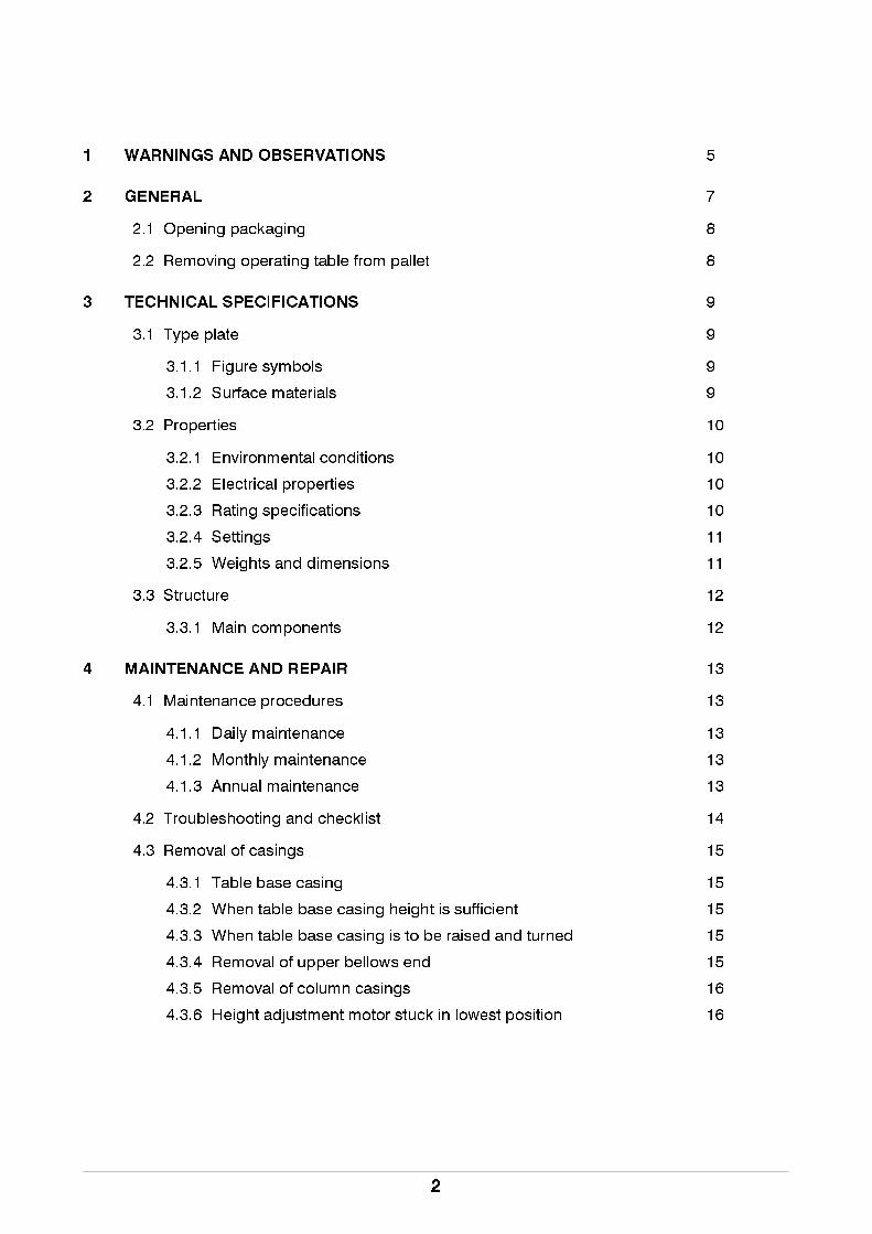
1 WARNINGS AND OBSERVATIONS 5
2 GENERAL 7
2.1 Opening packaging 8
2.2 Removing operating table from pallet 8
3 TECHNICAL SPECIFICATIONS 9
3.1 Type plate 9
3.1.1 Figure symbols 9
3.1.2 Surface materials 9
3.2 Properties 10
3.2.1 Environmental conditions 10
3.2.2 Electrical properties 10
3.2.3 Rating specifications 10
3.2.4 Settings 11
3.2.5 Weights and dimensions 11
3.3 Structure 12
3.3.1 Main components 12
4 MAINTENANCE AND REPAIR 13
4.1 Maintenance procedures 13
4.1.1 Daily maintenance 13
4.1.2 Monthly maintenance 13
4.1.3 Annual maintenance 13
4.2 Troubleshooting and checklist 14
4.3 Removal of casings 15
4.3.1 Table base casing 15
4.3.2 When table base casing height is sufficient 15
4.3.3 When table base casing is to be raised and turned 15
4.3.4 Removal of upper bellows end 15
4.3.5 Removal of column casings 16
4.3.6 Height adjustment motor stuck in lowest position 16
2
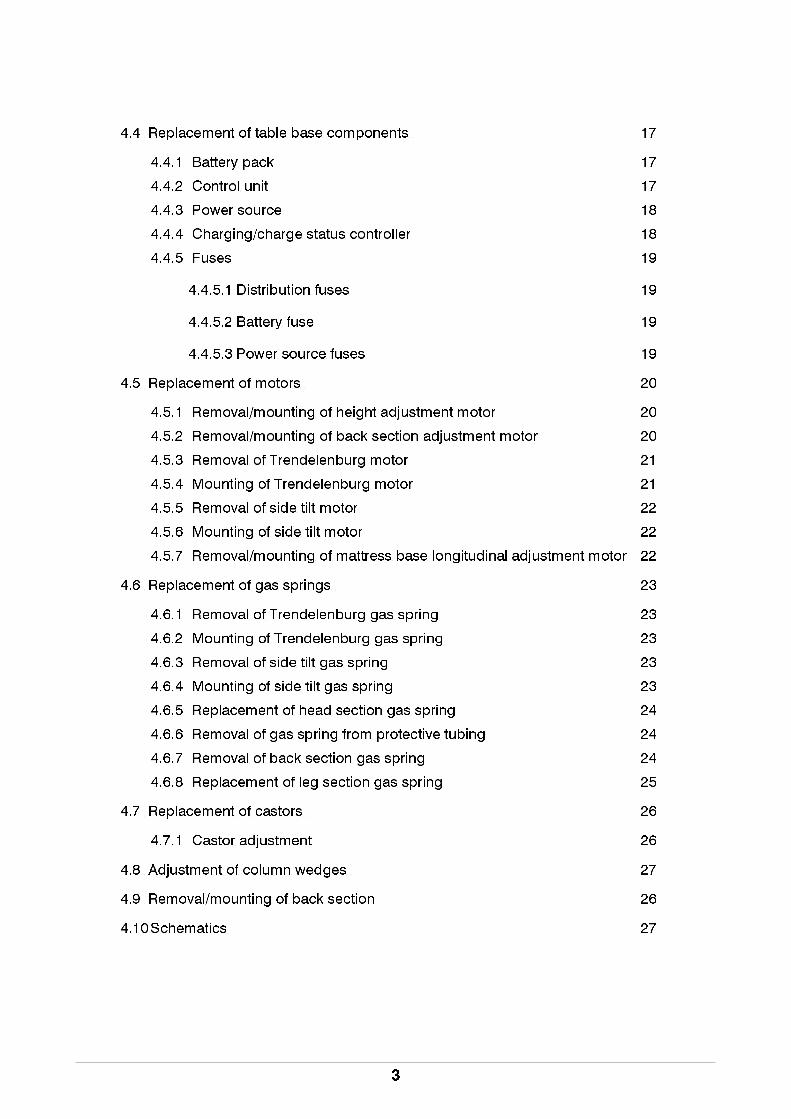
4.4 Replacement of table base components 17
4.4.1 Battery pack 17
4.4.2 Control unit 17
4.4.3 Power source 18
4.4.4 Charging/charge status controller 18
4.4.5 Fuses 19
4.4.5.1 Distribution fuses 19
4.4.5.2 Battery fuse 19
4.4.5.3 Power source fuses 19
4.5 Replacement of motors 20
4.5.1 Removal/mounting of height adjustment motor 20
4.5.2 Removal/mounting of back section adjustment motor 20
4.5.3 Removal of Trendelenburg motor 21
4.5.4 Mounting of Trendelenburg motor 21
4.5.5 Removal of side tilt motor 22
4.5.6 Mounting of side tilt motor 22
4.5.7 Removal/mounting of mattress base longitudinal adjustment motor 22
4.6 Replacement of gas springs 23
4.6.1 Removal of Trendelenburg gas spring 23
4.6.2 Mounting of Trendelenburg gas spring 23
4.6.3 Removal of side tilt gas spring 23
4.6.4 Mounting of side tilt gas spring 23
4.6.5 Replacement of head section gas spring 24
4.6.6 Removal of gas spring from protective tubing 24
4.6.7 Removal of back section gas spring 24
4.6.8 Replacement of leg section gas spring 25
4.7 Replacement of castors 26
4.7.1 Castor adjustment 26
4.8 Adjustment of column wedges 27
4.9 Removal/mounting of back section 26
4.10 Schematics 27
3
5 CLEANING 29
5.1Daily cleaning and disinfecting 29
5.1.1 Disinfecting: 29
5.1.2 Drying 29
6 RECYCLING 29
6.1Metals and plastics 29
6.1.1 Gas springs 29
4
!!
!
!
!
!
!
!
!
!
In order to ensure optimal surgical safety, all operating table users should
carefully read the operating table and maintenance instructions before using the table.
The entire surgical ward staff should be familiar with the correct use of the PRACTICO Operating table as well
as all warnings and observations concerning it.
Warnings and observations found in this instruction manual are indicated as follows:
WARNING! Please observe to ensure patient safety.
NOTE! Please observe in order to avoid causing damage to the equipment or its parts.
When setting the operating table into different positions, ensure that the patient’s fingers, hands or other
parts of the body are not caught between moving parts on the back/leg section or seat.
Always follow manufacturer instructions when using diatherm or defibrillation equipment.
Combustible anaesthetic gases must not be used with the table.
Before making any adjustment of the operating table, ensure that the patient will not fall.
Lock the castors before using the operating table.
Set the operating table surface as low as possible while transporting to ensure transport comfort. Transport
the operating table with the leg section at the front. Remember the directional castor!
Note! If the operating table surface is not raised high enough when the leg section is dropped into its lowest
position, it may impact with the table base casing damaging the operating table and creating pinching
hazard.
Note! If the operating table surface is not raised high enough when trendelenburg and side tilt are in their
extreme positions, back section may impact the table base casing damaging the operating table and
creating pinching hazard.
1. WARNINGS AND OBSERVATIONS !
5

!
!!!!!!!
!
!!!!!
When using the table, ensure that all accessories are properly mounted to it and check the function of acces-
sory lockings and adjustments.
When using the speciality headrest (100020126), ensure patient safety by releasing the headrest locking
before adjusting the back section. A warning label is affixed to the headrest.
The antistatic properties of the operating table require the use of Merivaara brand mattresses and antistatic
flooring.
Gas spring dismantling instructions are available from your sales representative. The release of nitrogen gas
is strictly prohibited, without following the proper instructions.
If the operating table has been in the cold, it must be allowed to warm up at room temperature for at least 6
hours before recharging the battery or switching on, to allow any condensation formed to evaporate.
All packaging cardboard should be recycled. Wood and plastics are energy waste.
The operating table is heavy (165 kg).
We recommend recharging the battery regularly overnight after a day’s use. This ensures that the table is
always ready for use and it extends the battery life. Charging takes approx. 5-10 hours, depending on the
battery charge status. The batteries also have sufficient capacity to be charged only once a week.
The equipotential point (DIN 42801) is located on the table base.
We recommend use of the equipotential point whenever operating and when using
patient monitoring equipment. Read all manufacturer instructions.
Dry the operating table carefully by wiping down with a dry cloth immediately after cleaning or disinfecting.
If the operating table batteries should quit during a procedure, connect the table to the main power supply
and continue as normal. Batteries can be charged while adjusting the table.
The switch in the table base can also be used as an emergency shutoff, if necessary.
Because batteries are problem waste, they must taken to a problem waste disposal facility.
When moving the operating table, ensure that any accessories mounted on the side or the back section
kidney elevator crank do not cause any damage.
WARNINGS AND OBSERVATIONS !
6

Dear operating table owner, The safe and fault-free use and maintenance of the equipment requires careful
adherence to these instructions. When mounting accessories to the equipment, the instructions provided
with them must be followed closely. Always keep the instructions for accessories together with this manual.
The Practico Operating Table meets the following standards: IEC 601-2-46, IEC 601-1-2 (EMC) and SFS-EN
60601-1. The table complies with directive 93/42/EEC (MDD) product class I, and bears a CE marking based
on this classification.
Intended use
The Merivaara Practico Operating Table is intended for general surgical use. It is also well suited for
outpatient surgical applications. The Practico works on both battery and mains power. The Practico can be
moved from one place to another. easily.
2. GENERAL
Expertise is essential.
The patient is the most important part of treatment.
This is precisely why the equipment used in
treatment must be absolutely
safe and convenient to use. As a health care
professional, you deserve the very best tools,
allowing you to concentrate on your own field of
expertise. Merivaara is an expert in providing
hospital equipment.
Merivaara products have been designed to
function
efficiently and flexibly during the various stages of
treatment. They assist you in the performance of
your work, without distracting you from the task at
hand.
Our integrated equipment system includes state-
of-the-art equipment for hospital procedures and
hospital room environments as well as for nursing
7

!!
!
2.1 Removing packaging
The operating table is preassembled in its packaging. Inspect the operating table for any shipping damage.
NOTE! If the operating table has been in the cold, allow it to warm up at room temperature for at least
6 hours before recharging the battery or switching on, to allow any condensation formed
to evaporate.
NOTE! All packaging cardboard should be recycled. Wood and plastics are energy waste.
2.2 Removal of operating table from pallet.
• Unscrew the M10x75 screw under the pallet.
• The permitted lifting area is indicated in Figure A.
NOTE! The operating table is heavy (165/175 kg).
o1045b.pdf
M10x75
8

3.1 Type plate
The type plate is located on the table base.
3.1.1 Figure symbols
STAND BY
Grounding
Equipotentiality
~ Alternating current
B-type device
Read instructions
Maximum allowable load (includes patient, mattress and accessories)
135 kg Maximum allowable load on operating table with longitudinal table surface
adjustment
Surface materials
• Stainless steel (accessory rails, mattress base parts)
• High-pressure laminate base panels
• Anodised aluminium
• Polyester (hand control board)
• EPDM rubber (bellows)
• ABS (column, table base casing)
3. TECHNICAL SPECIFICATIONS
Serial numbero1045h.pdf
Periodical operation (max) 1 min/10 min
Specific voltage, frequency and input power
Enclosure rating
Model
o1002h.eps
!
o1014b.eps
=180 kg
9
3.2 Properties
3.2.1 Environmental conditions
Ambient temperature +10- +40 °C
Ambient air pressure 700- 1060 mbar
Relative humidity 30 %- 75 %
Transport temperature -10- +40 °C
Storage temperature +10- +40 °C
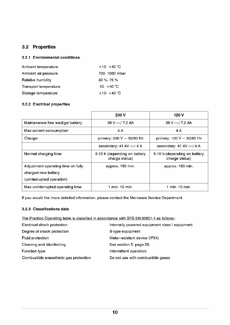
3.2.2 Electrical properties
If you would like more detailed information, please contact the Merivaara Service Department.
3.2.3 Classifications data
The Practico Operating table is classified in accordance with SFS-EN 60601-1 as follows::
Electrical shock protection Internally powered equipment class I equipment
Degree of shock protection B-type equipment
Fluid protection Water-resistant device (IPX4)
Cleaning and disinfecting See section 5. page 29.
Function type Intermittent operation
Combustible anaesthetic gas protection Do not use with combustible gases
230 V 120 V
Maintenance-free lead/gel battery 36 V / 7.2 Ah 36 V / 7.2 Ah
Max current consumption 4 A 4 A
Charger primary: 230 V ~ 50/60 Hz primary: 120 V ~ 50/60 Hz
secondary: 41.4V / 4 A secondary: 41.4V / 4 A
Normal charging time 5-10 h (depending on battery
charge status)
5-10 h (depending on battery
charge status)
Adjustment operating time on fully
charged new battery
(uninterrupted operation)
approx. 180 min. approx. 180 min.
Max uninterrupted operating time 1 min. 10 min. 1 min. 10 min.
10

3.2.4 Adjustments
Height adjustment 730-1030mm
Height adjustment, longitudinaldisplacement of table top 80-1080mm
Longitudinal displacement of table top 300mm
Side tilt ± 20°
Back section 100020120/100020130 -4° - +70°
Back section 100020131/100020135 -30° - +70°
Back section 100020122 -30° - +70°
Back section 100020125 -15° - +70°
Leg section -90° - +25°
Trendelenburg and anti-Trendelenburg 26°
Headrest (standard) - 45°- +30°
3.2.5 Weights and dimensions
Taulukko 1. Dimensions
STANDARD LONGITUDINAL
ADJUSTMENT
Operating table surface 4-part 4-part
Operating table weight 165 kg 175 kg
Length (A) 2040 mm 2040 mm
Width (B) 535 mm 535 mm
Height (C) 730-1030 mm 780-1080 mm
Table base length (D) 1080 mm 1080 mm
Mattress width (E) 540 mm 540 mm
Mattress base width (F) 594 mm 594 mm
Base panel height (G) 40 mm 40 mm
Castors 125 mm 125 mm
Longitudinal adjustment of mattress base 300mm
o1045i.pdf
Split leg section H=535mmOne-piece leg section H=505mm
11

3.3 Structure
3.3.1 Main components
Hand control
Head section
Seat section
Leg section
Equipotential point
o1045d.pdf
Directional castorControl unit
Batteries
o1046t.pdf
Side tilt motor
motor
Trendelenburg motor
Back section
Height adjustment
Charging outlet 230/120V
Switch
Power source
controller
Charging/charge status
Distribution fuses
Side tilt gas spring
Trendelenburg gas spring
12

!
!
4.1 Maintenance procedures
We recommend the following advance check-up and maintenance procedures to ensure continued
maintenance and trouble-free operation.
4.1.1 Daily maintenance
• During normal cleaning of the table, make a general visual inspection to ensure that it is in proper
working order.
• The PRACTICO Operating Table must be cleaned after each surgical procedure.
• We recommend that the batteries be charged every day. This will ensure a sufficient battery charge
and long service life
4.1.2 Monthly maintenance
• Lubricate all table joints with light machine oil.
• Ensure that all castors roll easily and lock securely.
• Check all table functions by fully extending and retracting them.
• Ensure that motor-equipped back sections are properly mounted to the seat. If necessary, tighten the
locking screws. See section 4.9 page 26.
• Ensure that the accessory rails are properly mounted.
4.1.3 Annual maintenance
• Perform all the same inspections as in monthly maintenance.
• Check and adjust column clearance, if required.
• Check cables and their connections.
All electrical repairs must be performed by a licensed electrician.
Before performing maintenance procedures:
• Disconnect power supply
• Turn switch to STAND BY position
• Support the table part being repaired before removing the motor or gas spring.
4. MAINTENANCE AND REPAIR
o1046b.pdf
13

4.2 Troubleshooting and checklist
When troubleshooting, check the following items first:
• Does the malfunction affect all table functions?
• Does the malfunction only affect one control function?
• If the problem only affects one control function, does it do so in both directions?
• Is the malfunction that the table does not move or that it will not maintain its position?
The following components are common to all systems. If there is a malfunction in these, all control functions
will be affected.
• Control unit
• Hand control unit
• Battery
• Power source/battery
If there is a malfunction in one of the following components, it usually affects only one function.
• Motor
• Gas spring
Malfunction Cause
Table adjustments do not function. • Switch is in STAND BY position
• Hand control is unplugged
• Battery is dead
• Fuse is blown
• Faulty hand control
• Faulty control unit
Table functions are sluggish and weak. • Low battery charge
• Faulty motor
Operating table function duration is short, even
though the battery has been charged in accordance
with instructions.
• Faulty charger
• Faulty battery
• Battery too old
Castors make abnormal noises when rolling • Pedal in wrong position
• Castor bearings worn
• Incorrect castor adjustment
14
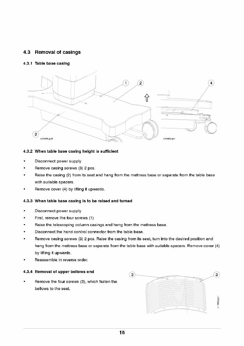
4.3 Removal of casings
4.3.1 Table base casing
4.3.2 When table base casing height is sufficient
• Disconnect power supply
• Remove casing screws (3) 2 pcs.
• Raise the casing (2) from its seat and hang from the mattress base or separate from the table base
with suitable spacers.
• Remove cover (4) by lifting it upwards.
4.3.3 When table base casing is to be raised and turned
• Disconnect power supply
• First, remove the four screws (1)
• Raise the telescoping column casings and hang from the mattress base.
• Disconnect the hand control connector from the table base.
• Remove casing screws (3) 2 pcs. Raise the casing from its seat, turn into the desired position and
hang from the mattress base or separate from the table base with suitable spacers. Remove cover (4)
by lifting it upwards.
• Reassemble in reverse order.
4.3.4 Removal of upper bellows end
• Remove the four screws (3), which fasten the
bellows to the seat.
1 2
3o1046b.pdf
4
3 3
o1046c.pdf
o1046v.pdf
15
!
!
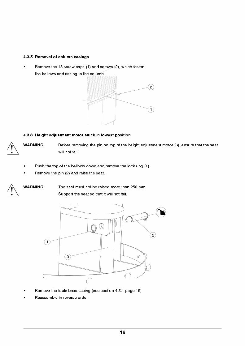
4.3.5 Removal of column casings
• Remove the 13 screw caps (1) and screws (2), which fasten
the bellows and casing to the column.
4.3.6 Height adjustment motor stuck in lowest position
WARNING! Before removing the pin on top of the height adjustment motor (3), ensure that the seat
will not fall.
• Push the top of the bellows down and remove the lock ring (1)
• Remove the pin (2) and raise the seat.
WARNING! The seat must not be raised more than 250 mm.
Support the seat so that it will not fall.
• Remove the table base casing (see section 4.3.1 page 15)
• Reassemble in reverse order.
2
1
2
1
3
16

4.4 Replacement of table base components
4.4.1 Battery pack
• Disconnect power supply
• Turn switch to STAND BY position
• Raise and turn the table base casing (see section 4.3.3 page 15)
• Disconnect the battery pack connector.
• Remove the mounting bar by unscrewing (1)
• Lift out the battery pack.
.
4.4.2 Control unit
• Disconnect power supply
• Turn switch to STAND BY position
• Raise and turn the table base casing (see section 4.3.3 page 15)
• Disconnect the control unit by pulling it up.
• Disconnect all connectors. Remember the positions of each connector!
Mounting bar
Battery pack
1
o1046g.pdf
Control unit
o1046g.pdf
17

4.4.3 Power source
• Disconnect power supply
• Turn switch to STAND BY position
• Raise and turn the table base casing (see section 4.3.3 page 15)
• Disconnect the battery pack connector.
• Disconnect the power source connection.
• Unscrew the mounting screws a few turns.
• Move the power source slightly to the side and lift out.
.
4.4.4 Charging/charge status controller
• Disconnect power supply
• Turn switch to STAND BY position
• Raise and turn the table base casing (see section 4.3.3 page 15)
• Disconnect the battery pack connector.
• Disconnect power source (see section 4.4.3 page 18)
• Disconnect charging/charge status controller connectors
• Unscrew the mounting screws a few turns.
• Lift out the charging/charge status controller.
Mounting screws
Mounting screws
Power source
o1046g.pdf
Move in the direction
of the arrow.
ScrewCharging controller
o1046h.pdf
18

4.4.5 Fuses
4.4.5.1 Mains fuses
• Position (see section 3.3.1 page 12)
• Open the fuse box and replace fuses.
4.4.5.2 Battery fuse
• Open battery casing cover
• Replace fuse
• Carfuse 15A Size: 5.3 x 19.1 x 18.7 mm.
4.4.5.3 Power source fuses
• Located inside the power source.
• Fuse T6.3A (2 pcs.)
Fuses T6.3A
o1046f.pdf
19
!
!
4.5 Replacement of motors
WARNING! Before opening the table base casing, disconnect the power supply.
WARNING! Before removing gas springs, ensure that the piston rod is locked or the spring is
unloaded.
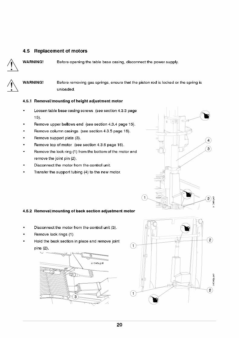
4.5.1 Removal/mounting of height adjustment motor
• Loosen table base casing screws (see section 4.3.3 page
15).
• Remove upper bellows end (see section 4.3.4 page 15).
• Remove column casings (see section 4.3.5 page 16).
• Remove support plate (3).
• Remove top of motor (see section 4.3.6 page 16).
• Remove the lock ring (1) from the bottom of the motor and
remove the joint pin (2).
• Disconnect the motor from the control unit.
• Transfer the support tubing (4) to the new motor.
4.5.2 Removal/mounting of back section adjustment motor
• Disconnect the motor from the control unit (3).
• Remove lock rings (1)
• Hold the back section in place and remove joint
pins (2).
3
4
21
o1046i.pdf
2
o1046p.pdf
1
1
2
3
o1046x.pdf
20
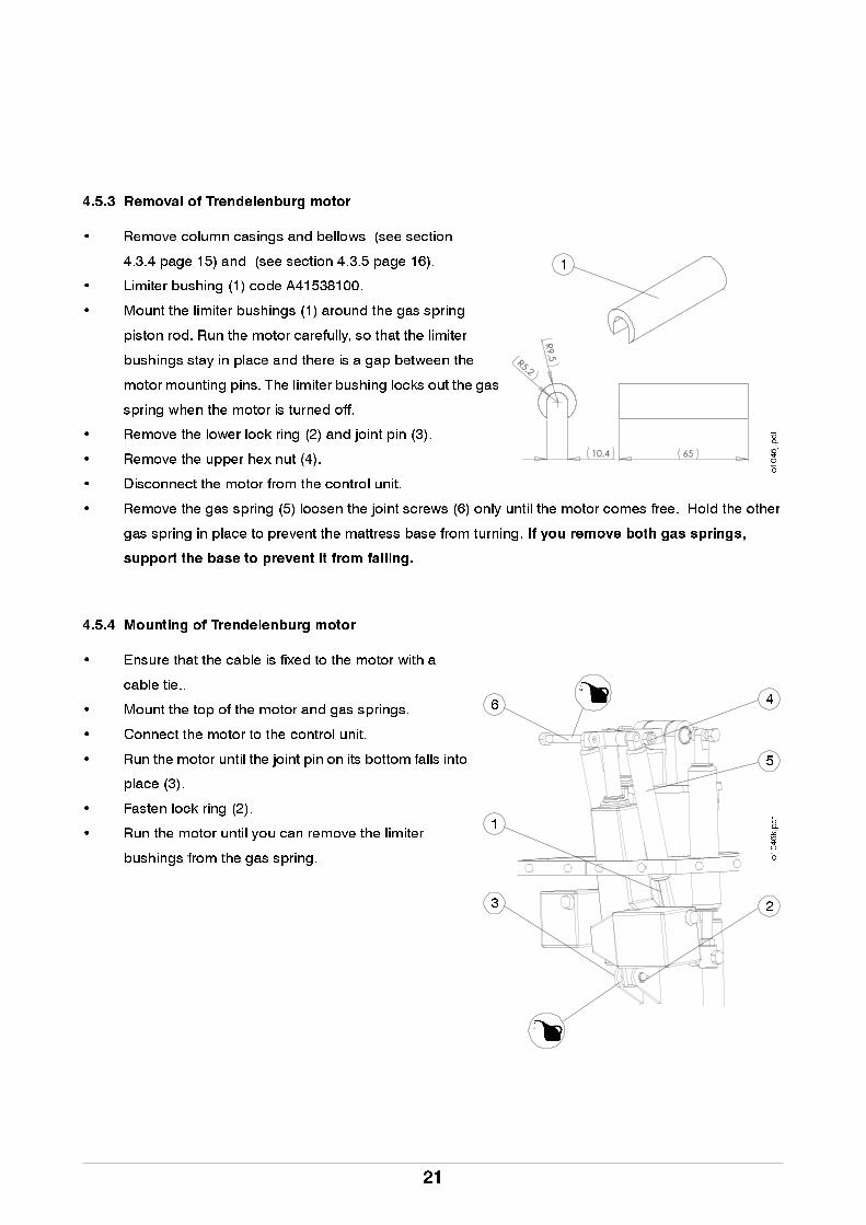
4.5.3 Removal of Trendelenburg motor
• Remove column casings and bellows (see section
4.3.4 page 15) and (see section 4.3.5 page 16).
• Limiter bushing (1) code A41538100.
• Mount the limiter bushings (1) around the gas spring
piston rod. Run the motor carefully, so that the limiter
bushings stay in place and there is a gap between the
motor mounting pins. The limiter bushing locks out the gas
spring when the motor is turned off.
• Remove the lower lock ring (2) and joint pin (3).
• Remove the upper hex nut (4).
• Disconnect the motor from the control unit.
• Remove the gas spring (5) loosen the joint screws (6) only until the motor comes free. Hold the other
gas spring in place to prevent the mattress base from turning. If you remove both gas springs,
support the base to prevent it from falling.
4.5.4 Mounting of Trendelenburg motor
• Ensure that the cable is fixed to the motor with a
cable tie..
• Mount the top of the motor and gas springs.
• Connect the motor to the control unit.
• Run the motor until the joint pin on its bottom falls into
place (3).
• Fasten lock ring (2).
• Run the motor until you can remove the limiter
bushings from the gas spring.
����
����
����
�
1
o1046j.pdf
6
23
5
4
o1046k.pdf
1
21
!
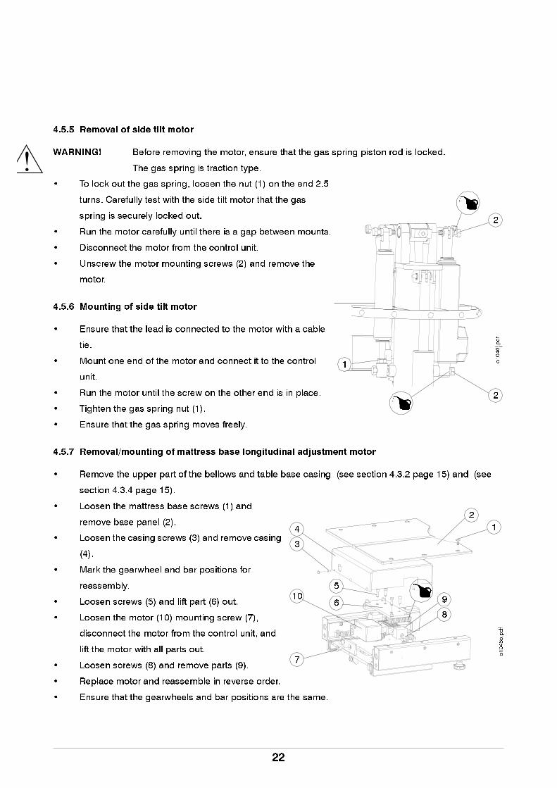
4.5.5 Removal of side tilt motorWARNING! Before removing the motor, ensure that the gas spring piston rod is locked.
The gas spring is traction type.
• To lock out the gas spring, loosen the nut (1) on the end 2.5
turns. Carefully test with the side tilt motor that the gas
spring is securely locked out.
• Run the motor carefully until there is a gap between mounts.
• Disconnect the motor from the control unit.
• Unscrew the motor mounting screws (2) and remove the
motor.
4.5.6 Mounting of side tilt motor
• Ensure that the lead is connected to the motor with a cable
tie.
• Mount one end of the motor and connect it to the control
unit.
• Run the motor until the screw on the other end is in place.
• Tighten the gas spring nut (1).
• Ensure that the gas spring moves freely.
4.5.7 Removal/mounting of mattress base longitudinal adjustment motor
• Remove the upper part of the bellows and table base casing (see section 4.3.2 page 15) and (see
section 4.3.4 page 15).
• Loosen the mattress base screws (1) and
remove base panel (2).
• Loosen the casing screws (3) and remove casing
(4).
• Mark the gearwheel and bar positions for
reassembly.
• Loosen screws (5) and lift part (6) out.
• Loosen the motor (10) mounting screw (7),
disconnect the motor from the control unit, and
lift the motor with all parts out.
• Loosen screws (8) and remove parts (9).
• Replace motor and reassemble in reverse order.
• Ensure that the gearwheels and bar positions are the same.
2
2
1 o1046l.pdf
14
o1046o.pdf
2
3
9
8
7
106
5
22
!
4.6 Replacement of gas springs
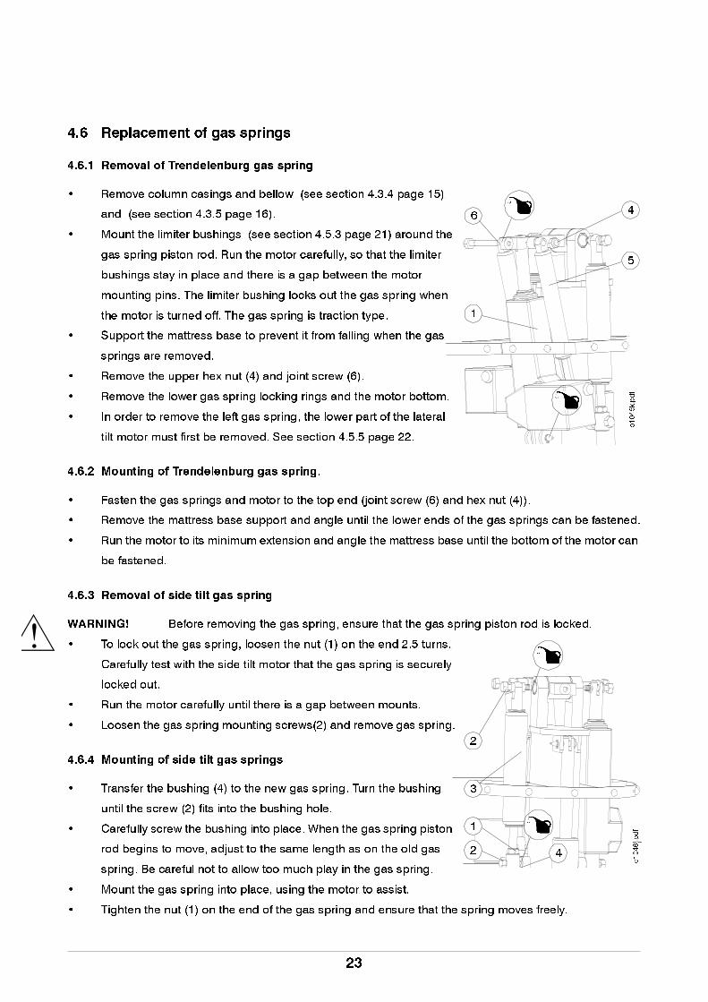
4.6.1 Removal of Trendelenburg gas spring
• Remove column casings and bellow (see section 4.3.4 page 15)
and (see section 4.3.5 page 16).
• Mount the limiter bushings (see section 4.5.3 page 21) around the
gas spring piston rod. Run the motor carefully, so that the limiter
bushings stay in place and there is a gap between the motor
mounting pins. The limiter bushing locks out the gas spring when
the motor is turned off. The gas spring is traction type.
• Support the mattress base to prevent it from falling when the gas
springs are removed.
• Remove the upper hex nut (4) and joint screw (6).
• Remove the lower gas spring locking rings and the motor bottom.
• In order to remove the left gas spring, the lower part of the lateral
tilt motor must first be removed. See section 4.5.5 page 22.
4.6.2 Mounting of Trendelenburg gas spring.
• Fasten the gas springs and motor to the top end (joint screw (6) and hex nut (4)).
• Remove the mattress base support and angle until the lower ends of the gas springs can be fastened.
• Run the motor to its minimum extension and angle the mattress base until the bottom of the motor can
be fastened.
4.6.3 Removal of side tilt gas spring
WARNING! Before removing the gas spring, ensure that the gas spring piston rod is locked.
• To lock out the gas spring, loosen the nut (1) on the end 2.5 turns.
Carefully test with the side tilt motor that the gas spring is securely
locked out.
• Run the motor carefully until there is a gap between mounts.
• Loosen the gas spring mounting screws(2) and remove gas spring.
4.6.4 Mounting of side tilt gas springs
• Transfer the bushing (4) to the new gas spring. Turn the bushing
until the screw (2) fits into the bushing hole.
• Carefully screw the bushing into place. When the gas spring piston
rod begins to move, adjust to the same length as on the old gas
spring. Be careful not to allow too much play in the gas spring.
• Mount the gas spring into place, using the motor to assist.
• Tighten the nut (1) on the end of the gas spring and ensure that the spring moves freely.
6
5
4
o1046k.pdf
1
1
2
2
3
o1046l.pdf
4
23

4.6.5 Replacement of head section gas spring
• Raise the head section into its upper position.
• Remove locking ring (1)
• Remove pin (2).
• Loosen the nut (3).
• Unscrew the gas spring (4). Count the
number of turns for reassembly.
4.6.6 Removal of gas spring from protective tubing
• Remove the gas spring ram (1).
• Pull the gas spring (2) out of the protective tubing (3).
• Unscrew the mount (4). Count the number of turns
for reassembly.
• If the gas spring requires adjustment:
• first turn the mounting bracket (4) to its old position
• adjust only by half a turn or one whole turn at a time
• if the gas spring is still under load, turn counterclockwise
• if lifting the handle does not release the gas spring, turn clockwise
4.6.7 Replacement of back section gas spring
• Replace gas springs one at a time, so that one is left to
support the back section.
• Raise the back section into its upper position.
• Remove screws (1) and bushings (2).
• Turn the accessory rail (3) to the side.
• Remove the locking ring (4).
• Remove the retaining screws (7).
• Remove pins (5).
• Remove gas spring (6).
• Removal of gas spring from protective tubing (see
section 4.6.6 page 24)
3
1
24
o1046n.pdf
o1009g.eps
1
2
3
4
1
6
5
2
1
34
2
5
o1046n.pdf
7
24
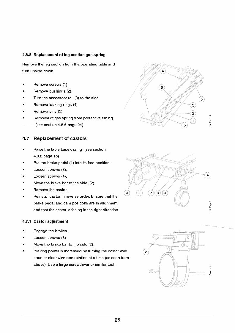
4.6.8 Replacement of leg section gas spring
Remove the leg section from the operating table and
turn upside down.
• Remove screws (1).
• Remove bushings (2).
• Turn the accessory rail (3) to the side.
• Remove locking rings (4)
• Remove pins (5).
• Removal of gas spring from protective tubing
(see section 4.6.6 page 24)
4.7 Replacement of castors
• Raise the table base casing (see section
4.3.2 page 15)
• Put the brake pedal (1) into its free position.
• Loosen screws (3).
• Loosen screws (4).
• Move the brake bar to the side. (2).
• Remove the castor.
• Reinstall castor in reverse order. Ensure that the
brake pedal and cam positions are in alignment
and that the castor is facing in the right direction.
4.7.1 Castor adjustment
• Engage the brakes.
• Loosen screws (3).
• Move the brake bar to the side (2).
• Braking power is increased by turning the castor axle
counter-clockwise one rotation at a time (as seen from
above). Use a large screwdriver or similar tool.
o1046u.pdf
51
2
6
4
4
5
3
o1046r.pdf
21 33 4
4
o1046s.pdf
2
25
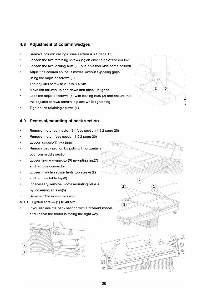
4.8 Adjustment of column wedges
• Remove column casings (see section 4.3.1 page 15).
• Loosen the two retaining screws (1) on either side of the column.
• Loosen the two locking nuts (2), one on either side of the column.
• Adjust the column so that it moves without exposing gaps
using the adjuster screws (3).
The adjuster screw torque is 3-4 Nm.
• Move the column up and down and check for gaps.
• Lock the adjuster screws (3) with locking nuts (2) and ensure that
the adjuster screws remain in place while tightening.
• Tighten the retaining screws (1).
4.9 Removal/mounting of back section
• Remove motor connector (6) (see section 4.5.2 page 20)
• Remove motor (see section 4.5.2 page 20)
• Loosen screws(1) two turns.
• Remove back section by pulling it horizontally
out from middle section.
• Loosen frame connector(6) mounting nut(7)
and remove connector.
• Loosen middle section table top screws(2)
• and remove table top(3).
• If necessary, remove motor mounting plate(4)
by loosening screws(5)
• Re-assemble in reverse order.
NOTE! Tighten screws (1) to 40 Nm.
• If you replace the back section with a different model,
ensure that the motor is facing the right way.
31 2
o1026h.eps
2
1
2
45 5
3
7
6
26
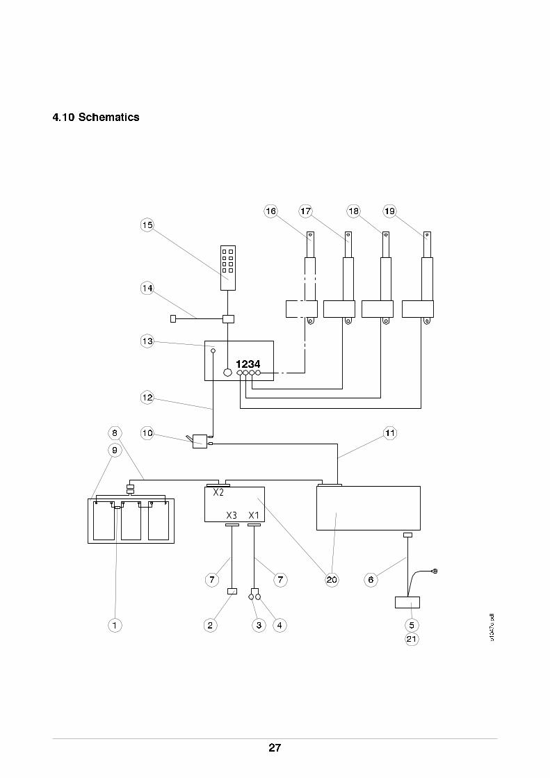
4.10 Schematics
1
o1047c.pdf
6
3 5
77
8
9
10 11
12
13
14
16 17 18 19
15
2
20
21
1234
4
27
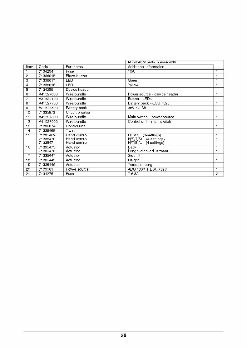
Number of parts in assembly
Item Code Part name Additional information
1 7134254 Fuse 15A 1
2 71336015 Piezo buzzer 1
3 71336017 LED Green 1
4 71336016 LED Yellow 1
5 7134259 Device header 1
6 A41527600 Wire bundle Power source – device header 1
7 A31529100 Wire bundle Buzzer - LEDs 1
8 A41527700 Wire bundle Battery pack – ESU 7320 1
9 A21513500 Battery pack 36V 7.2 Ah 1
10 71335972 Circuit breaker 1
11 A41527800 Wire bundle Main switch – power source 1
12 A41527900 Wire bundle Control unit – main switch 1
13 71336074 Control unit 1
14 71335468 T-wire 1
15 713354697133547071335471
Hand controlHand controlHand control
H/T/St (3-settings)H/S/T/St (4-settings)H/T/St/L (4-settings)
111
16 7133547571335476
ActuatorActuator
BackLongitudinal adjustment
11
17 71335447 Actuator Side tilt 1
18 71335442 Actuator Height 1
19 71335446 Actuator Trendelenburg 1
20 7133561 Power source ADC 4380 + ESU 7320 1
21 7134275 Fuse T 6.3A 2
28
!
5.1 Daily cleaning and disinfecting
The PRACTICO Operating Table should be cleaned after every surgical procedure, before beginning another
surgery. The mattresses and operating table surface are cleaned by wiping down with a lightly alkaline
detergent
(pH 7-8).
5.1.1 Disinfecting:
Wipe down with a 3% chloramine-based disinfectant (Klorilli) or similar cleaning agent.
Normal excretion stains from patients are cleaned and disinfected with a 10% chloramine-based disinfectant.
Excretion stains from isolation patients are cleaned and disinfected with a 25% chloramine-based
disinfectant.
5.1.2 Drying
NOTE! Dry the operating table carefully by wiping down with a dry cloth immediately after cleaning or
disinfecting.
5. CLEANING
29

!!
6.1 Metals and plastics
When disposing of an operating table or replacing any of its parts, check the recyclability of each item. A
majority of the metal used on the operating table is steel. The operating table also contains a number of zinc
and aluminium castings and brass bushings. When recycling plastic parts, determine the material type. The
surface materials list will provide assistance in determining the correct recycling procedure. If a part material
is missing from the table, contact your sales representative. For more information on recycling, contact your
local waste management facility or visit related sites on the Internet.
Below are recycling symbols, which are marked on parts made of plastic. Products marked with these
symbols can be used as energy waste.
6.1.1 Gas springs
Gas springs can be disposed of as metal waste after all nitrogen gas and oil has been removed from them.
WARNING! The release of nitrogen gas is strictly prohibited, without following the proper instructions.
Gas spring dismantling instructions are available from your sales representative.
NOTE! Because batteries are problem waste, they must be taken to a problem waste disposal
facility.
6. RECYCLING
30

31
NOTESvaaraMeri-