
Practical Real-Time Voxel-Based Global Illumination for Current...
56
PRACTICAL REAL-TIME VOXEL-BASED GLOBAL ILLUMINATION FOR CURRENT GPUS Alexey Panteleev NVIDIA
Transcript of Practical Real-Time Voxel-Based Global Illumination for Current...

PRACTICAL REAL-TIME VOXEL-BASED GLOBAL
ILLUMINATION FOR CURRENT GPUS
Alexey Panteleev
NVIDIA

2
OUTLINE
Introduction: what is Global Illumination?
Screenshots
Overview of Voxel Cone Tracing
Our main innovation: 3D clipmap
Implementation details
Performance

3
WHAT IS GLOBAL ILLUMINATION? Here is a flashlight that lights the floor.

4
WHAT IS GLOBAL ILLUMINATION? Here is a flashlight that lights the floor.
Light bounces off the floor
and hits the surrounding objects.
5
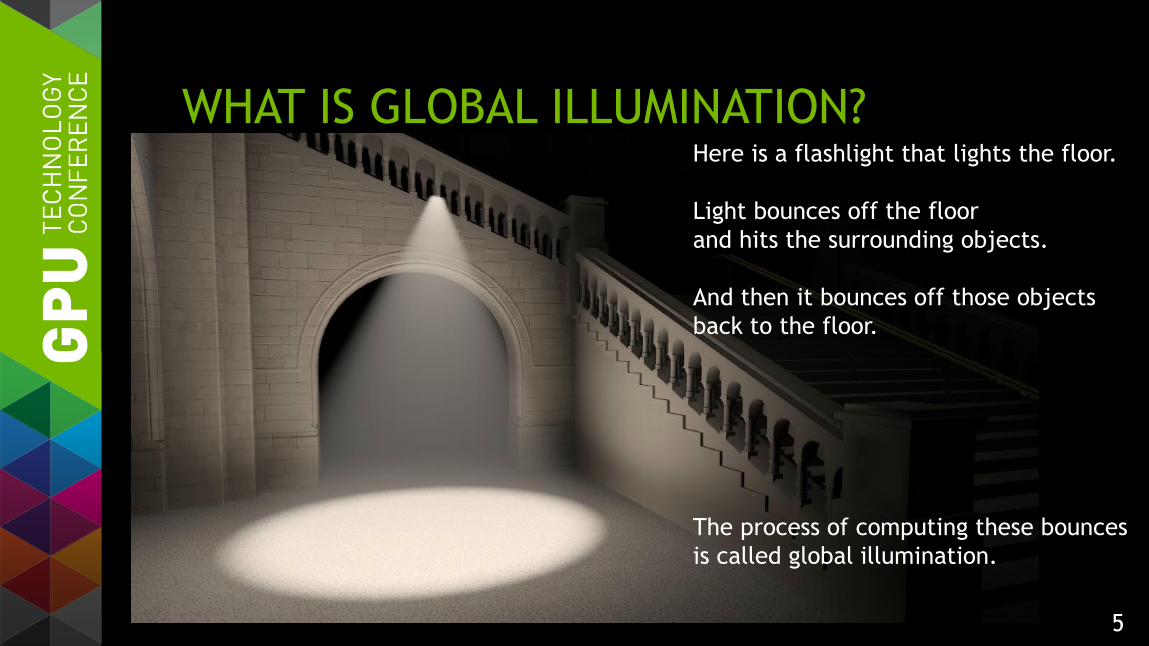
WHAT IS GLOBAL ILLUMINATION? Here is a flashlight that lights the floor.
Light bounces off the floor
and hits the surrounding objects.
And then it bounces off those objects
back to the floor.
The process of computing these bounces
is called global illumination.
6
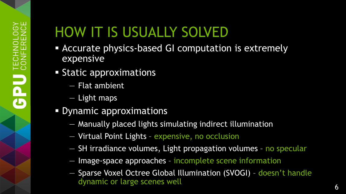
HOW IT IS USUALLY SOLVED Accurate physics-based GI computation is extremely
expensive
Static approximations
— Flat ambient
— Light maps
Dynamic approximations
— Manually placed lights simulating indirect illumination
— Virtual Point Lights – expensive, no occlusion
— SH irradiance volumes, Light propagation volumes – no specular
— Image-space approaches – incomplete scene information
— Sparse Voxel Octree Global Illumination (SVOGI) – doesn’t handle dynamic or large scenes well
7
OUR SOLUTION Dynamic approximation
— No offline pre-computations
— Handles dynamic scenes easily
Voxel Cone Tracing
— “Interactive Indirect Illumination Using Voxel Cone Tracing” by Cyril Crassin, Fabrice Neyret, Miguel Sainz, Simon Green, Elmar Eisemann
Gathering information from a multi-resolution voxel representation of the scene
8
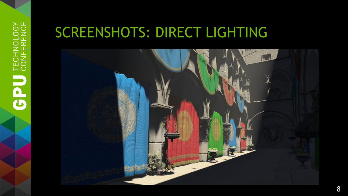
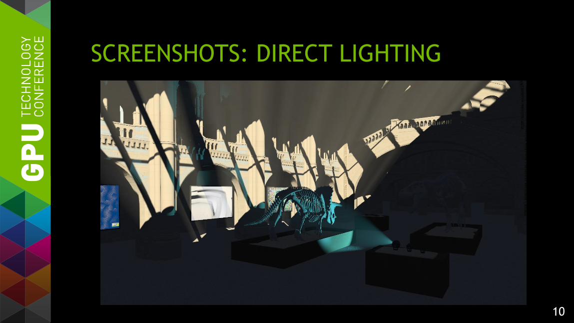
SCREENSHOTS: DIRECT LIGHTING

9
SCREENSHOTS: GI
10
SCREENSHOTS: DIRECT LIGHTING

11
SCREENSHOTS: GI
12
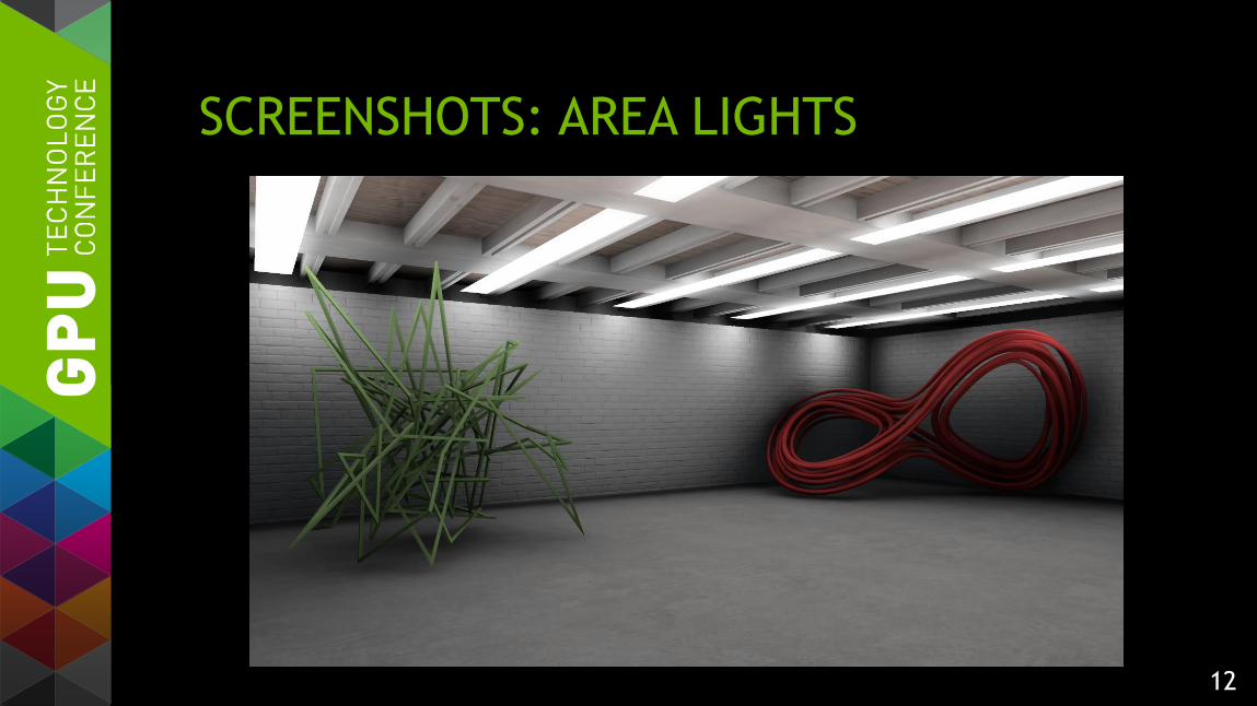
SCREENSHOTS: AREA LIGHTS

13
SCREENSHOTS: FLAT AMBIENT
14
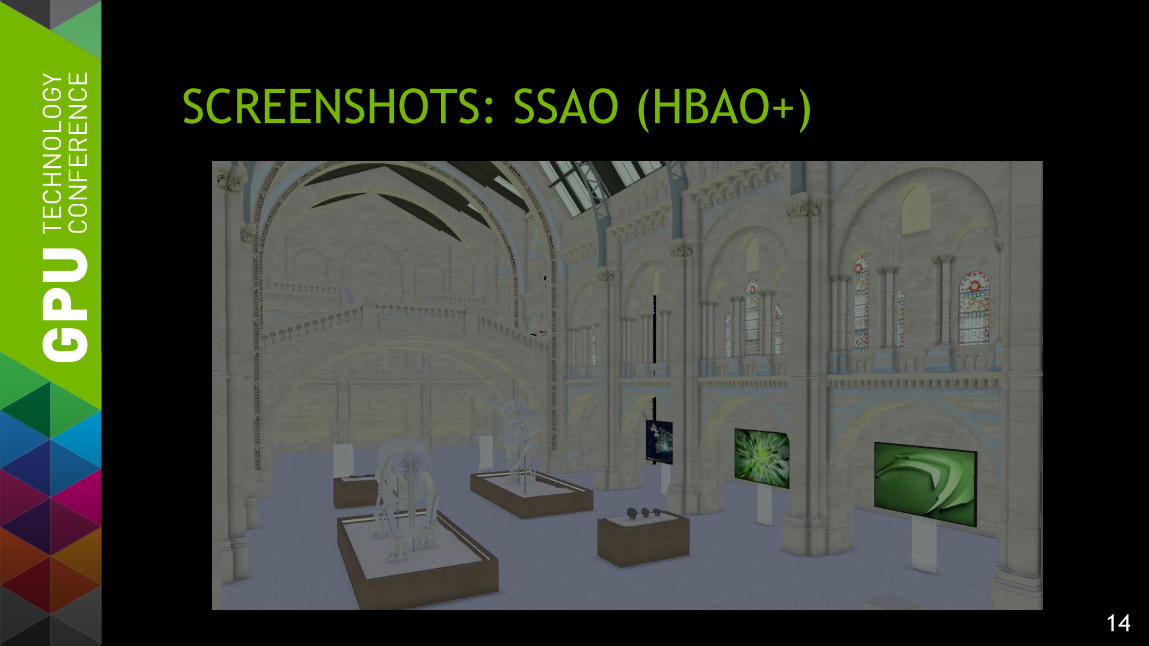
SCREENSHOTS: SSAO (HBAO+)
15
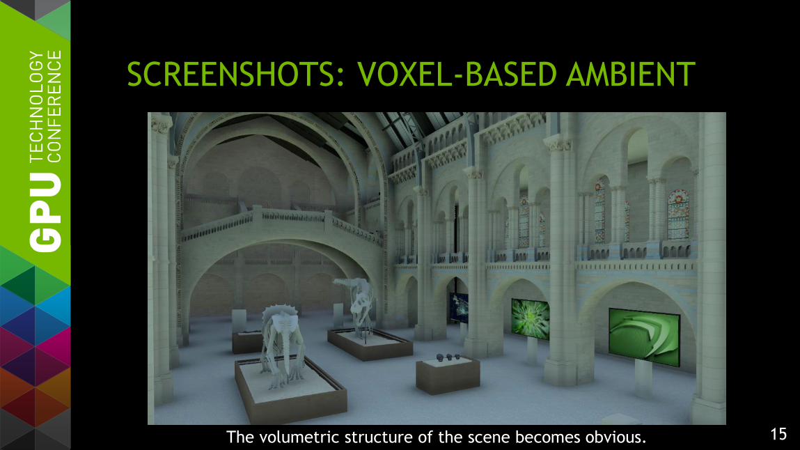
SCREENSHOTS: VOXEL-BASED AMBIENT
The volumetric structure of the scene becomes obvious.

16
OVERVIEW OF VOXEL CONE TRACING Transform the scene into voxels that encode opacity
— Then downsample the opacity map
Render reflective shadow maps (RSMs)
Translate RSMs into another voxel map encoding emittance
— Then downsample the emittance map
Gather light by tracing cones through the opacity and emittance maps
17
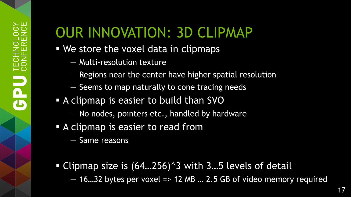
OUR INNOVATION: 3D CLIPMAP We store the voxel data in clipmaps
— Multi-resolution texture
— Regions near the center have higher spatial resolution
— Seems to map naturally to cone tracing needs
A clipmap is easier to build than SVO
— No nodes, pointers etc., handled by hardware
A clipmap is easier to read from
— Same reasons
Clipmap size is (64…256)^3 with 3…5 levels of detail
— 16…32 bytes per voxel => 12 MB … 2.5 GB of video memory required
18
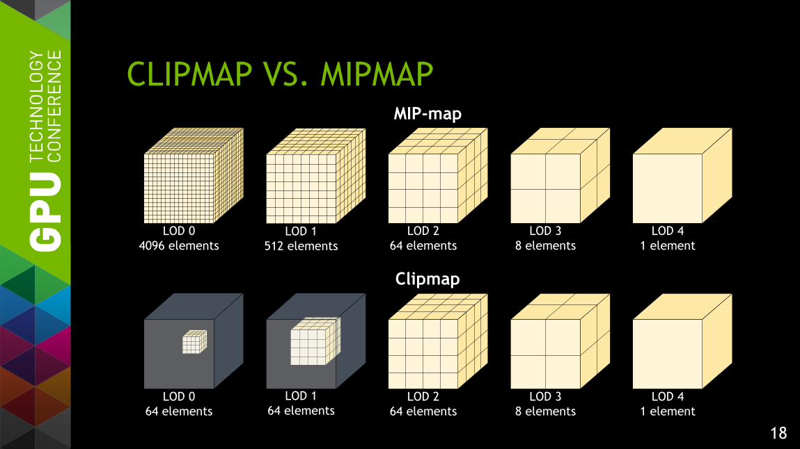
CLIPMAP VS. MIPMAP
LOD 2
64 elements
LOD 1
64 elementsLOD 0
64 elements
LOD 3
8 elements
LOD 4
1 elementLOD 1
512 elements
LOD 0
4096 elements
Clipmap
MIP-map
LOD 2
64 elements
LOD 3
8 elements
LOD 4
1 element
19
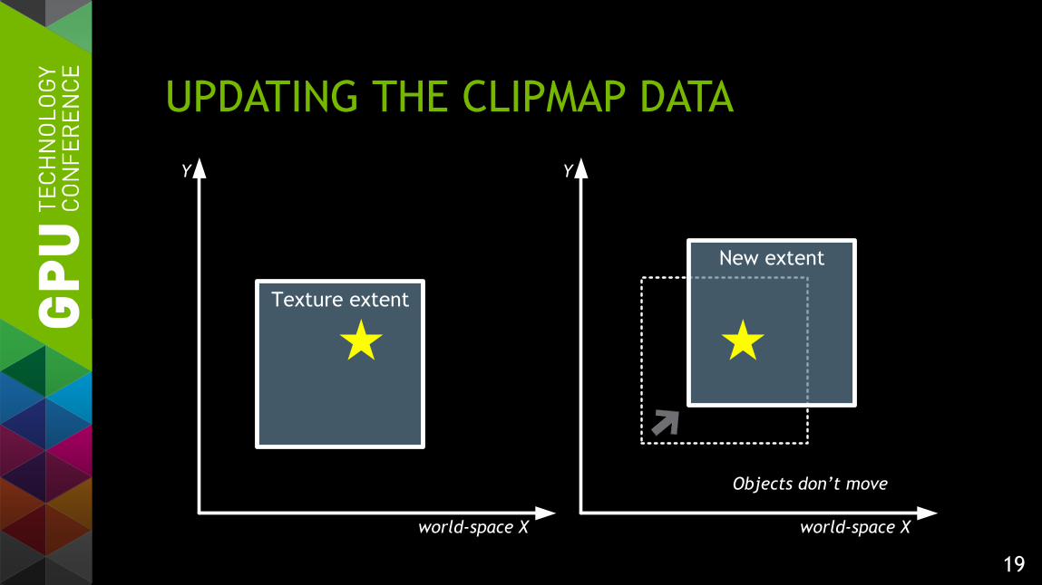
UPDATING THE CLIPMAP DATA
Texture extent
New extent
Objects don’t move
world-space X world-space X
Y Y

20
TOROIDAL ADDRESSING
The background shows texture addresses: frac(worldPos.xy / levelSize.xy)
A fixed point in space always maps to the same address in the clipmap.
1, 1
0, 0 1, 0
0, 1 1, 1
0, 0 1, 0
0, 1
1, 1
0, 0 1, 0
0, 1 1, 1
0, 0 1, 0
0, 1
1, 1
0, 0 1, 0
0, 1 1, 1
0, 0 1, 0
0, 1
1, 1
0, 0 1, 0
0, 1 1, 1
0, 0 1, 0
0, 1
world-space X world-space X
Y Y

21
INCREMENTAL UPDATES: CLIPMAP MOVES When the camera moves, most of the clipmap data remains valid.
1, 1
0, 0 1, 0
0, 1 1, 1
0, 0 1, 0
0, 1
1, 1
0, 0 1, 0
0, 1 1, 1
0, 0 1, 0
0, 1
1, 1
0, 0 1, 0
0, 1 1, 1
0, 0 1, 0
0, 1
1, 1
0, 0 1, 0
0, 1 1, 1
0, 0 1, 0
0, 1
Kept
Revoxelized
world-space X world-space X
Y Y

22
INCREMENTAL UPDATE: OBJECTS MOVE If some objects change, only the corresponding regions need to be revoxelized.
world-space X world-space X
Y Y
Revoxelized
Kept

23
VOXEL TEXTURE CONTENTS Opacity textures
— 3 or 6 opacity directions for each voxel
— “How opaque is the voxel when viewed from a certain direction”
— 3 for HQ tracing, 6 for LQ tracing: less self-shadowing
— Stored as 1 or 2 RGB10A2 textures
Emittance textures
— 3 or 6 emittance directions for each voxel
— “How much light does the voxel emit to a certain direction”
— 6 for HQ and second-bounce tracing, 3 for LQ tracing
— Stored as 3 or 6 RGB10A2 sRGB textures (non atomically updatable)
24
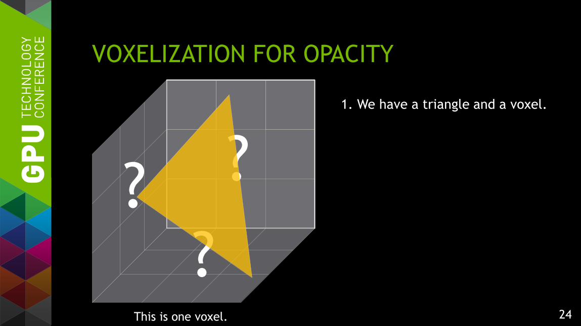
VOXELIZATION FOR OPACITY
1. We have a triangle and a voxel.
?
??
This is one voxel.

25
VOXELIZATION FOR OPACITY
2. Select the projection plane that
yields the biggest projection area
(the back face in this case).
?
??

26
VOXELIZATION FOR OPACITY
3. Rasterize the triangle using
MSAA to compute one coverage
mask per pixel.
Actual MSAA pattern is different,
but we translate those samples
onto a regular grid.
??
27
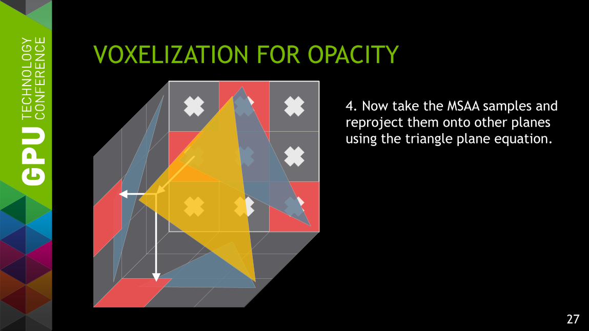
VOXELIZATION FOR OPACITY
4. Now take the MSAA samples and
reproject them onto other planes
using the triangle plane equation.

28
VOXELIZATION FOR OPACITY
5. Repeat that process for all
covered samples.
29
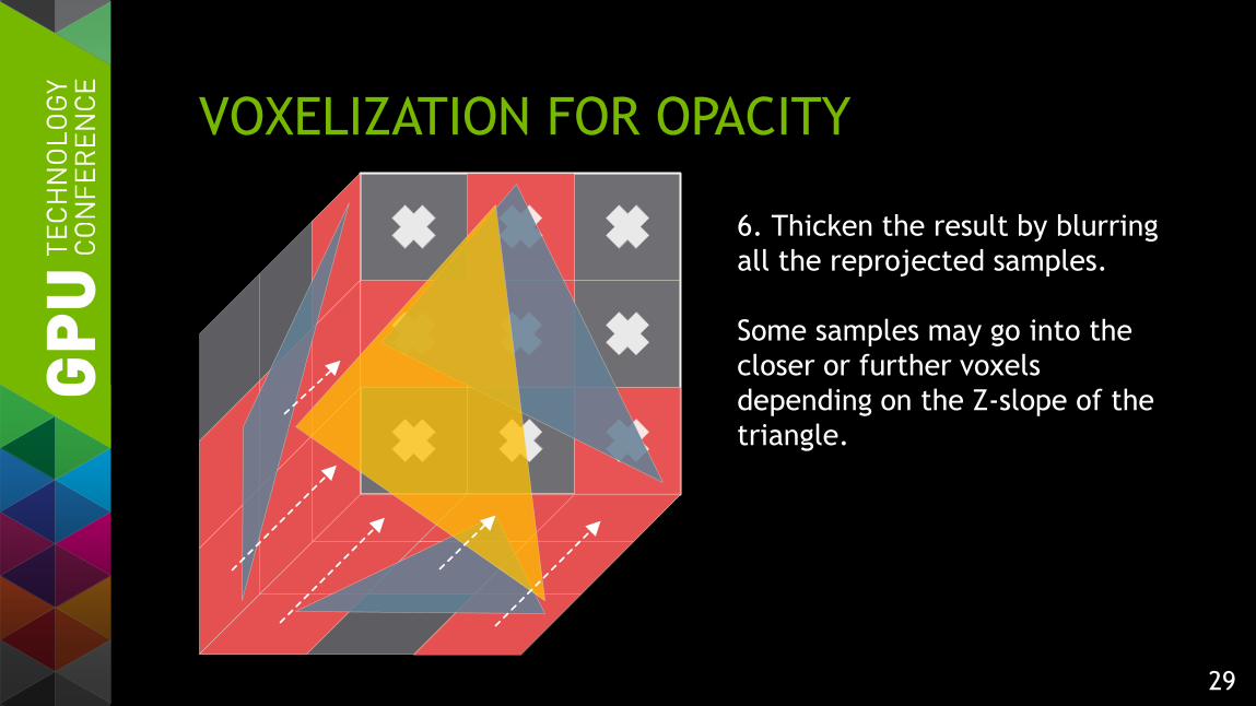
VOXELIZATION FOR OPACITY
6. Thicken the result by blurring
all the reprojected samples.
Some samples may go into the
closer or further voxels
depending on the Z-slope of the
triangle.

30
VOXELIZATION: SCENE GEOMETRY

31
VOXELIZATION: DIRECTIONAL COVERAGE
32
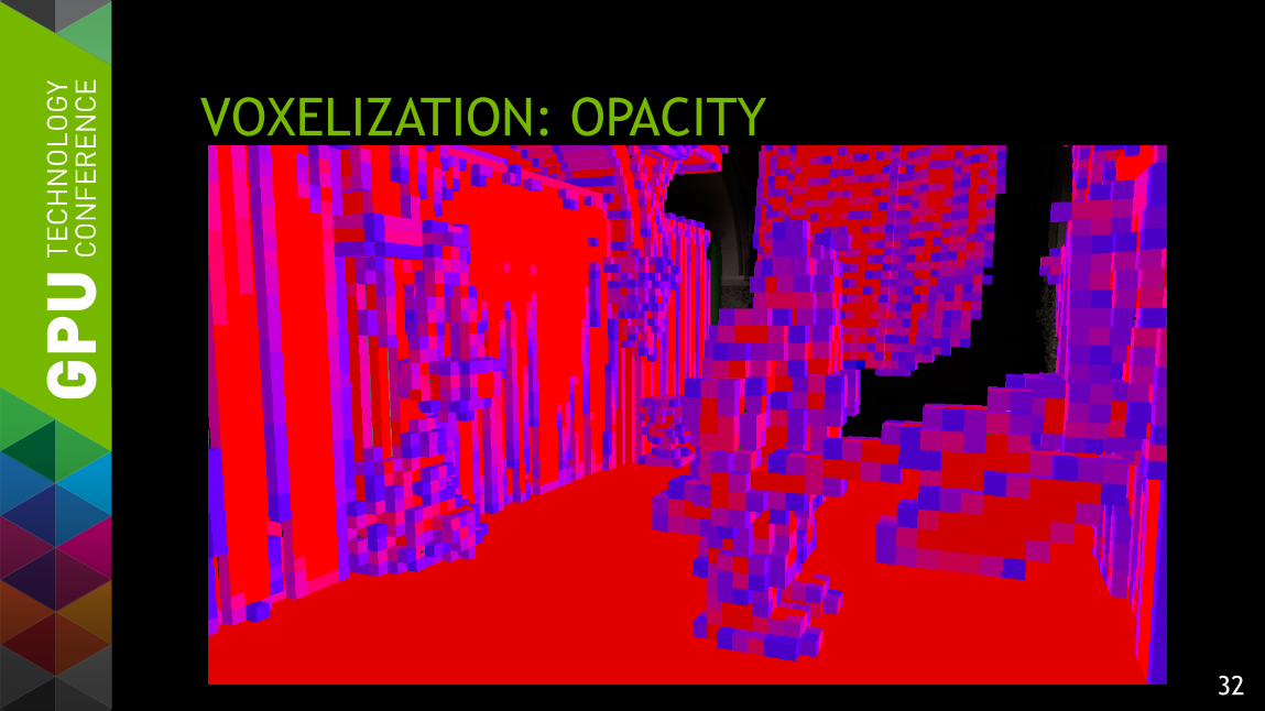
VOXELIZATION: OPACITY
33
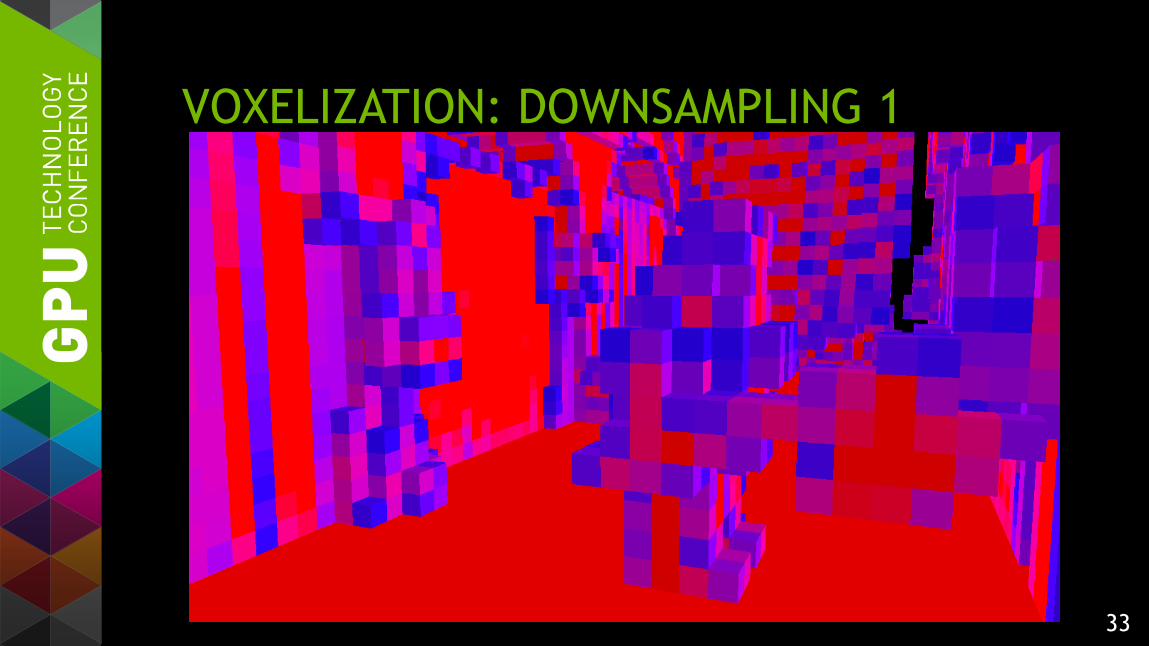
VOXELIZATION: DOWNSAMPLING 1

34
VOXELIZATION: DOWNSAMPLING 2

35
VOXELIZATION FOR EMITTANCE Step 1: compute approximate brightness for each voxel
— Use the coverage mask to weigh the emittance texture/color
Step 2: accumulate the brightness and normal in emittance textures
— There are 6 textures, one per direction, storing RGB10 sRGB data
— Need R32U to perform atomics => 3 textures for emittance, 3 for normal
Step 3: Convert the brightness data to directional emittance
36
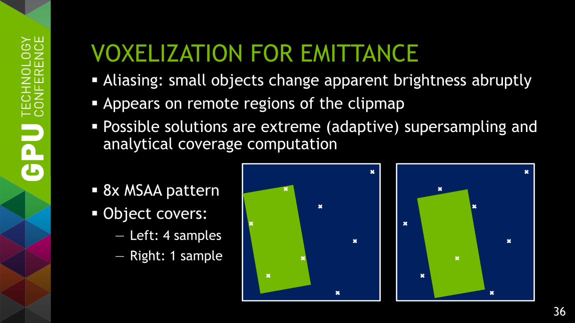
VOXELIZATION FOR EMITTANCE Aliasing: small objects change apparent brightness abruptly
Appears on remote regions of the clipmap
Possible solutions are extreme (adaptive) supersampling and analytical coverage computation
8x MSAA pattern
Object covers:
— Left: 4 samples
— Right: 1 sample
37
MULTI-RESOLUTION VOXELIZATION
MIP-map: downsample finer levels to get coarser levels
Clipmap: there are no finer levels for most of coarser levels
Rasterize every triangle at several resolutions
— Obtain center regions of coarser levels by downsampling finer levels
— Use GS instancing to rasterize one triangle several times

38
MULTI-RESOLUTION VOXELIZATION
Voxelization with downsampling yields higher quality results than multi-res voxelization.
Rasterize… Downsample once Downsample twice
39
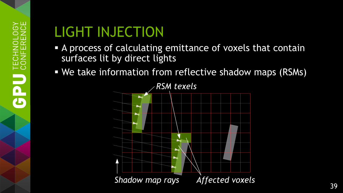
LIGHT INJECTION A process of calculating emittance of voxels that contain
surfaces lit by direct lights
We take information from reflective shadow maps (RSMs)
Shadow map rays
RSM texels
Affected voxels
40
LIGHT INJECTION ALGORITHMS Simplest option: test every voxel center against the RSM
— Consider only voxels with nonzero opacity
— If a voxel is lit, take the color and normal from the RSM
— Problems: aliasing, false lighting on object boundaries
Better option: gather all RSM texels that belong to the voxel
— Many texture fetches per voxel, most of them are useless
Even better option: scatter RSM texels into voxels using atomic operations
— Requires more memory, which we allocate sparsely in a separate texture

41
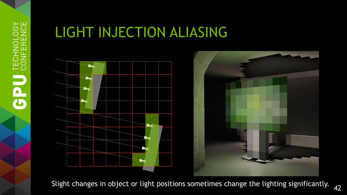
LIGHT INJECTION ALIASING
Slight changes in object or light positions sometimes change the lighting significantly.
42
LIGHT INJECTION ALIASING
Slight changes in object or light positions sometimes change the lighting significantly.

43
LIGHT INJECTION PRE-FILTERING
Need to pre-filter the RSM point cloud before injecting
— Every texel will affect more than 1 voxel (3^3 or even 5^3)
— Expensive to inject with scattering: atomics will be a bottleneck
Impractical to use the same filter kernel for all clip levels
— A kernel that removes aliasing on all levels is very large
Different filter kernel sizes may result in injected/downsampled mismatch

44
CONE TRACING BASICS Several cones are traced from every visible surface
A cone marches through the clipmap accumulating:
— transparency (1-opacity)
— illumination (emittance * transparency)
Each sample is taken
from a coarser LOD
than the previous one. 1
0transparencyillumination
45
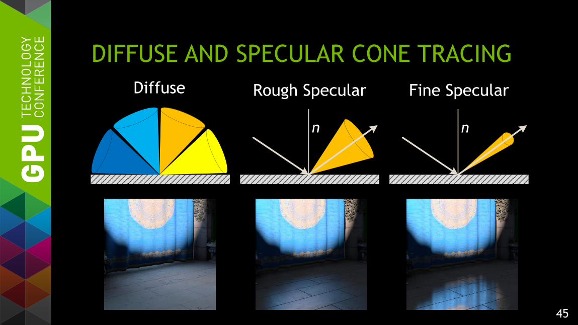
DIFFUSE AND SPECULAR CONE TRACING
Diffuse
n
Rough Specular
n
Fine Specular

46
SPARSE DIFFUSE CONE TRACING
Diffuse lighting is usually low-frequency
— HQ cone tracing for every pixel is redundant
We trace every Nth pixel on the screen
— N = 4…16
— Rotated grid pattern to reduce aliasing
Interpolate using a bilateral filter
— MSAA resolve fits naturally into the interpolation pass

47
LIGHT LEAKING
Lit surfaces
A coarse voxel
Indirect lighting receiver
Unilt samples
Lit sample

48
PERFORMANCE Full GI is practical on current mainstream GPUs
— e.g. GeForce GTX 770
Voxel-based AO works well on low-end GPUs, too
— Looks much better than SSAO
GI processing time per frame, in ms:
AO only Med High Ultra
GTX 650 (GK107) 14.3 28.1
GTX 770 (GK104) 3.8 7.4 12.9
GTX TITAN (GK110) 3.1 6.6 9.6 25.4
@ 1920x1080
49
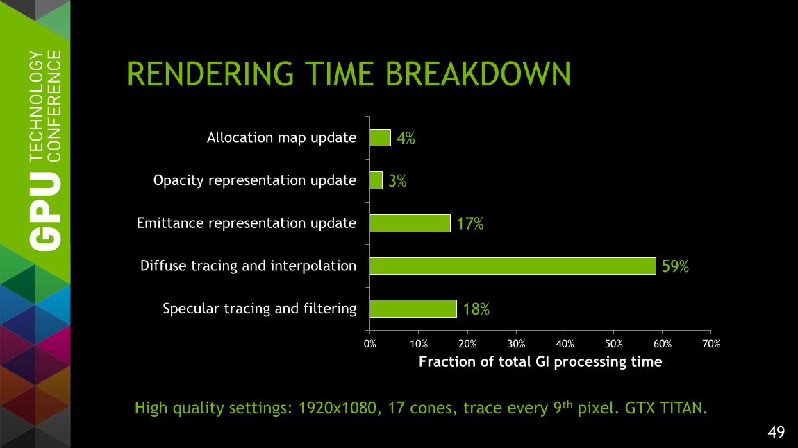
RENDERING TIME BREAKDOWN
18%
59%
17%
3%
4%
0% 10% 20% 30% 40% 50% 60% 70%
Specular tracing and filtering
Diffuse tracing and interpolation
Emittance representation update
Opacity representation update
Allocation map update
Fraction of total GI processing time
High quality settings: 1920x1080, 17 cones, trace every 9th pixel. GTX TITAN.

50
CONCLUSION
Fully dynamic GI becomes practical on mainstream GPUs
— Low end GPUs can benefit from much higher-quality AO
Future work
— Further reduction of aliasing issues
— Reduce the amount of content changes necessary
Planned to be released as NVIDIA GI Works library

51
QUESTIONS?
mailto: [email protected]
Thanks:
— Cyril Crassin Yury Uralsky
— Evgeny Makarov Sergey Bolotov
— Khariton Kantiev Alexey Barkovoy
— Monier Maher Miguel Sainz
— Holger Gruen

52
BACKUP

53
SPARSE DIFFUSE CONE TRACING
8.0 ms tracing
0.7 ms interpolation
4.0 ms tracing
0.75 ms interpolation
3.0 ms tracing
0.8 ms interpolation
Every 4th pixel Every 9th pixel Every 16th pixel
Measured on a GTX 680 at 1280x800, no AA, 17 diffuse cones.
54
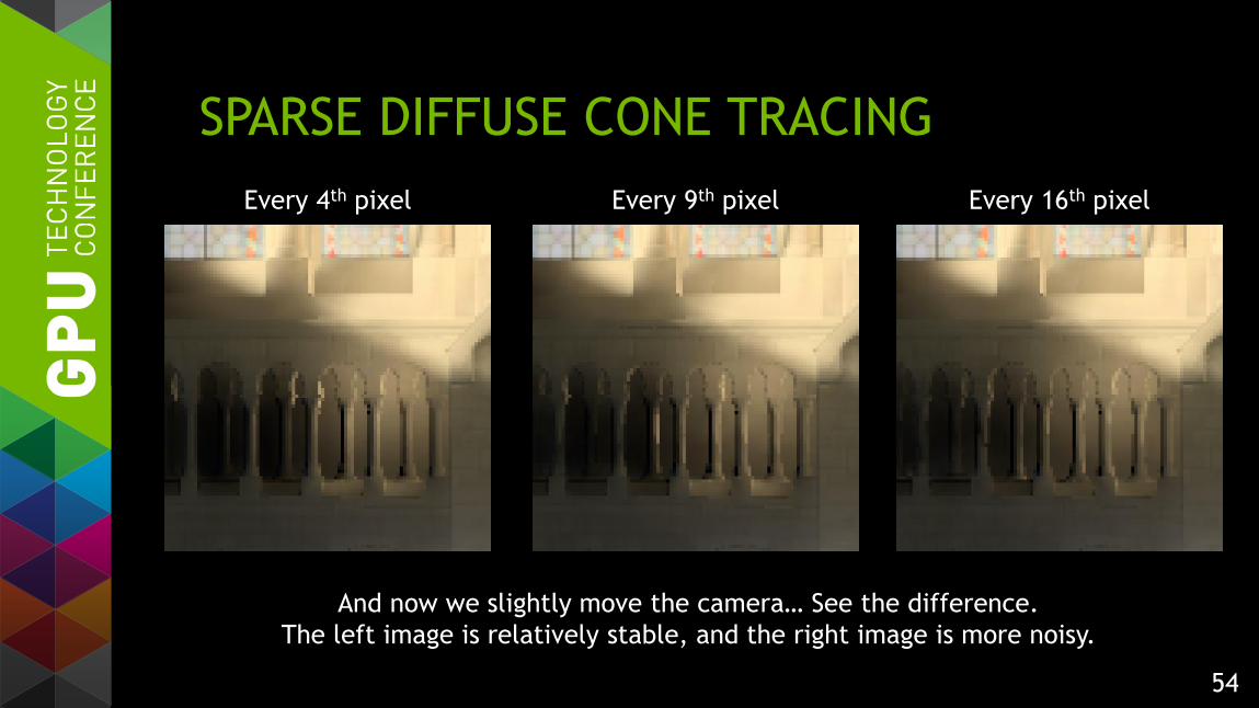
SPARSE DIFFUSE CONE TRACING
And now we slightly move the camera… See the difference.
The left image is relatively stable, and the right image is more noisy.
Every 4th pixel Every 9th pixel Every 16th pixel
55
NOISY SPECULAR CONE TRACING Tracing specular cones sparsely only works for flats
— And a low tracing step is needed to avoid banding
Dense tracing is expensive due to small tracing step
— Large step results in banding
We use noisy dense tracing:
— Add a pseudo-random offset to every specular cone
— Use a 4x4 blue noise matrix bound to screen pixels
— Trace with step = 1.0 voxels
— Filter the results with a 4x4 kernel + bilateral

56
SPECULAR BANDING REMOVAL
Banding in dense tracing Adding noise… And filtering that noise.
The images are displayed with enhanced contrast.


![Volumetric 3D Mapping in Real-Time on a CPU · Volumetric 3D Mapping in Real-Time on a CPU ... narrow band around the observed surface. ... [8]; class Brick Voxel voxel[8][8][8];](https://static.fdocuments.in/doc/165x107/5b87b0e77f8b9a1a248d44a2/volumetric-3d-mapping-in-real-time-on-a-cpu-volumetric-3d-mapping-in-real-time.jpg)

