PRACTICAL ASPECTS OF APPLYING BROADBAND ACTIVE … · PRACTICAL ASPECTS OF APPLYING BROADBAND...
22
1 PRACTICAL ASPECTS OF APPLYING BROADBAND ACTIVE HARMONIC FILTERS ON FOUR APPLICATIONS Copyright Material IEEE Paper No. 178 Ian C. Evans James R. Johnson Managing Director Member, IEEE Harmonics Solutions Co. UK Product Manager – AccuSine Dunfermline, Fife, Scotland UK Schneider Electric – North America [email protected] Salem, Oregon USA [email protected] Abstract – The use of nonlinear devices has made the electrical world a lot more complex. Many of the nonlinear loads cause electrical problems such as flicker, harmonics, poor displacement power factor, and current in-rush requirements that conventional solutions fail to remedy. Active harmonic filters bring a new perspective to the problems and yield surprising results. However, there are two predominant logic designs and only one provides the speed and total control required for these tough applications. This paper presents four applications that are difficult to resolve and discusses the two types of active harmonic filter designs. Index Terms – Active harmonic filters, flicker, harmonics, inter-harmonics, broadband active harmonic filters, displacement power factor, total harmonic current distortion [THDi], Total harmonic voltage distortion [THDv], total power factor INTRODUCTION Active harmonic filters (aka active filters) were introduced in the mid-late 1990’s and were adopted over the next few years as an expensive but technically viable alternative to passive L-C filters and transformer based phase shifting techniques, either via multi-pulse drives or quasi multi-pulse systems. The possibility of resonance, still a potential problem associated with passive L-C filters, no longer exists if active filters are used. Extensive electrical system studies, also associated with passive filters, are no longer required if active filters are used. Active filters are complex, with power conversion technology similar to that used in AC PWM variable frequency drives (see Figs 1 and 2). They can be expensive but, depending on the type of active filter and the application on which installed, can provide excellent performance, often reducing the “total harmonic current distortion” (THDi) to below 5%. Today, active filters are often installed without any real consideration of the application requirements. They are seen as a simple, “quick fix” to most applications by consultants and others who do not fully understand what active filters are and what they can and cannot achieve. They are often viewed as ‘ready made solutions’ to all the power systems harmonics and other power quality ills. This misconception is often mirrored in manufacturer’s publicity material. One issue, for example, that is often not appreciated is what happens when an active filter is connected to a non linear load. Due to the very low source impedance (typically <1%) for harmonic currents the non linear load will draw more harmonic current from the active filter than it would from a utility transformer (or generator source). Therefore, the rating of the active filter has to be calculated based on the active filter in circuit and NOT from harmonic current measurements taken based on the normal operating conditions. Precautions therefore have to be taken to limit the rise in harmonic current (and associated total harmonic voltage distortion (THDv) to acceptable levels when the active filter is installed. These precautions may include additional AC line reactance to be inserted should there be insufficient reactance present in the non linear load(s). Active filters can also provide reactive current compensation for the displacement power factor in addition to improving the real or true power factor via harmonic treatment of the load. The degree of success is largely determined by three factors; firstly the application and what is expected to be achieved (e.g. are uncharacteristic harmonics and/or inter-harmonics to be treated or SCR line notching to be attenuated.). Secondly, where the active filter is to be inserted in the power system is extremely important (e.g. if installed too far upstream the voltage distortion still may be problematic at local levels). Finally, the type of active filter employed; its speed of response; and control strategy are of crucial importance to a large number of applications, especially where the non linear load is of a dynamic nature. As can be seen in the next section active filters can usually be broken down into two distinct types. SELECTIVE FFT v BROADBAND – THE DIFFERENCES IN PERFORMANCE The two prevalent types of logic implementation in active filters are digital and analog. Both monitor the load current via current transformers. How the logic handles the load current information makes for large performance variations. Most digital logic systems employ fast Fourier transforms (FFT) to calculate the amplitude and phase angle of each
Transcript of PRACTICAL ASPECTS OF APPLYING BROADBAND ACTIVE … · PRACTICAL ASPECTS OF APPLYING BROADBAND...

1
PRACTICAL ASPECTS OF APPLYING BROADBAND ACTIVE HARMONIC FILTERS ON FOUR APPLICATIONS
Copyright Material IEEE
Paper No. 178 Ian C. Evans James R. Johnson
Managing Director Member, IEEE Harmonics Solutions Co. UK Product Manager – AccuSine Dunfermline, Fife, Scotland UK Schneider Electric – North America [email protected] Salem, Oregon USA [email protected]
Abstract – The use of nonlinear devices has made the electrical world a lot more complex. Many of the nonlinear loads cause electrical problems such as flicker, harmonics, poor displacement power factor, and current in-rush requirements that conventional solutions fail to remedy. Active harmonic filters bring a new perspective to the problems and yield surprising results. However, there are two predominant logic designs and only one provides the speed and total control required for these tough applications. This paper presents four applications that are difficult to resolve and discusses the two types of active harmonic filter designs. Index Terms – Active harmonic filters, flicker, harmonics, inter-harmonics, broadband active harmonic filters, displacement power factor, total harmonic current distortion [THDi], Total harmonic voltage distortion [THDv], total power factor
INTRODUCTION
Active harmonic filters (aka active filters) were introduced in the mid-late 1990’s and were adopted over the next few years as an expensive but technically viable alternative to passive L-C filters and transformer based phase shifting techniques, either via multi-pulse drives or quasi multi-pulse systems. The possibility of resonance, still a potential problem associated with passive L-C filters, no longer exists if active filters are used. Extensive electrical system studies, also associated with passive filters, are no longer required if active filters are used. Active filters are complex, with power conversion technology similar to that used in AC PWM variable frequency drives (see Figs 1 and 2). They can be expensive but, depending on the type of active filter and the application on which installed, can provide excellent performance, often reducing the “total harmonic current distortion” (THDi) to below 5%. Today, active filters are often installed without any real consideration of the application requirements. They are seen as a simple, “quick fix” to most applications by consultants and others who do not fully understand what active filters are and what they can and cannot achieve. They are often viewed as ‘ready made solutions’ to all the
power systems harmonics and other power quality ills. This misconception is often mirrored in manufacturer’s publicity material. One issue, for example, that is often not appreciated is what happens when an active filter is connected to a non linear load. Due to the very low source impedance (typically <1%) for harmonic currents the non linear load will draw more harmonic current from the active filter than it would from a utility transformer (or generator source). Therefore, the rating of the active filter has to be calculated based on the active filter in circuit and NOT from harmonic current measurements taken based on the normal operating conditions. Precautions therefore have to be taken to limit the rise in harmonic current (and associated total harmonic voltage distortion (THDv) to acceptable levels when the active filter is installed. These precautions may include additional AC line reactance to be inserted should there be insufficient reactance present in the non linear load(s). Active filters can also provide reactive current compensation for the displacement power factor in addition to improving the real or true power factor via harmonic treatment of the load. The degree of success is largely determined by three factors; firstly the application and what is expected to be achieved (e.g. are uncharacteristic harmonics and/or inter-harmonics to be treated or SCR line notching to be attenuated.). Secondly, where the active filter is to be inserted in the power system is extremely important (e.g. if installed too far upstream the voltage distortion still may be problematic at local levels). Finally, the type of active filter employed; its speed of response; and control strategy are of crucial importance to a large number of applications, especially where the non linear load is of a dynamic nature. As can be seen in the next section active filters can usually be broken down into two distinct types.
SELECTIVE FFT v BROADBAND – THE DIFFERENCES IN PERFORMANCE
The two prevalent types of logic implementation in active filters are digital and analog. Both monitor the load current via current transformers. How the logic handles the load current information makes for large performance variations. Most digital logic systems employ fast Fourier transforms (FFT) to calculate the amplitude and phase angle of each

2
harmonic order. The digital conversion from the analog load current requires three cycles of current to make the FFT determination. Then according to the selections made by the operators, an injection current is calculated. The final step converts the digital information into an analog signal for the converter to inject. The entire process requires about 40 milliseconds for each calculation. Some of the FFT products measure the harmonic current to the 50th order, but select 15 or 20 harmonic orders for cancellation. This severely limits the performance capability of the active filter. Attaining 5% total harmonic current distortion (THDi) levels is not likely. The analog method receives the current transformer data; removes the base frequency component via a notch filter; and then injects the inverse of the remaining curve into the AC lines. This real time process requires ½-1 cycle (< 16 milliseconds) to complete. The logic makes no attempt to define each harmonic order. Instead the logic sees the whole and injects to remove the whole from the electrical system. This logic has been identified as the broadband logic system. An additional benefit of broadband logic is the removal of inter-harmonics (i.e. non fundamental and non characteristic harmonic orders of varying frequencies). Since there is no attempt to define the make up of the ‘noise,’ all ‘noise’ is removed. Broadband logic results in lower harmonic levels removed faster than FFT logic. Finally, one additional feature that results from broadband logic is in-rush support. Broadband logic sees step load changes in 40 microseconds and begins injecting within 100 microseconds to support reactive current needs of the loads. This benefit will become very evident in the following examples. CASE STUDIES USING BROADBAND ACTIVE FILTER
As can now be appreciated the selection of the type of active filter is of crucial importance. The following brief case studies will illustrate the type of performance which can be expected with real time, broadband active filters.
DUTCH OIL PLATFORM; DISPLACEMENT POWER FACTOR & HARMONIC CONTROL
The operators of an oil platform off the coast of The Netherlands experienced several types of operational problems when down sizing efforts were initiated. This platform had been in operation for nearly 20 years. In 2002 the production was approximately 2000 barrels a day. The problem was that the output was 98% salt water. Therefore, downsizing was carried out. The original configuration included two 6.25 MVA gas turbine driven generators operating in parallel plus an identical back up generator. The loads consisted of five electrical submersible pumps (ESPs) rated at 600 kW each connected to 6 kV, two export pumps rated 700 kW each operating at 6 kV, a water injection pump rated 400 kW operating at 6 kV, and the lighting, living quarters, and office loads typically associated with oil platforms at a total load of 800 kVA. The export pumps and water injection pump operated directly on the AC line at 6 kV.
The lighting, living quarters, and office loads all operated on a single bus rated at 380 VAC. The five ESPs operated on 480V AC variable speed drives (VSD) via 6.6kV/0.48kV transformers, which were installed 16 years ago to increase pumping efficiencies. The changes to the platform included removing a generator, three down-hole pump systems, an export pump, and the water injection pump. The remaining export pumps were downsized from 700 kW at 6 kV to 300 kW at 380 V. This resulted in approximately 3 MVA of loads operating on one 6.25 MVA generator (see Fig 3). The specific problems that occurred after the conversion were constant flicker of the entire lighting network, mechanical resonance that caused the entire structure to “shiver”, and limitations in the capacity of the down-hole pumps with a resulting financial loss. The problems occurred when either one or both of the down-hole pumps was operating. SITE ANALYSIS Site analysis was carried out. It was established that the total loading on the generator was about 3 MVA, less than 50% of the generator rating. It was believed that the generator was more than adequate for the load and the cyclical variations that occur. A voltage oscillation of 30 Hz was also found. The first item investigated was the automatic voltage regulator (AVR) on the generator. It was thought that the regulator was failing to hold regulation and thus generator instability occurred. The AVR was replaced with more current technology. However, all efforts to improve the function of the generator via improved AVR function failed. The mechanical resonance and flicker continued no matter how the AVR was adjusted. The input power at each ESP drive was examined. It was noted that for K8 and K4 ESPs the THDv was about 9% and 11% while the THDi was about 29% and 30% respectively. The displacement power factors (DPF) were 0.85 lag and 0.84 lag respectively for K8 and K4 due to the fully controlled SCR input rectifiers in each drive. The results clearly indicate high level harmonic contributions to the 6 kV bus. GENERATOR CONSIDERATIONS Discussions with the generator manufacturer advised that automatic voltage regulators (AVR) are capable of maintaining regulation as long as the voltage distortion is below 10 – 15% THD(V) and displacement power factor (DPF) is not less than 0.75 lag at medium load conditions (0.80 DPF at full load). AVR struggle to maintain line voltage when either or both parameters are exceeded. The initial reaction is oscillation of line voltage. As line voltage varies the loads will respond by varying the current drawn in order to maintain the kW required for operation of the load. This causes the AVR to struggle more. At some point the voltage/current oscillations cause mechanical resonance in the rotating load. When the mechanical resonance coincides with the frequency of the mechanical structure, resonance of a structure occurred causing the ‘shiver.’

3
To stop the voltage oscillation, THDv must be reduced or DPF improved or both depending upon the severity of each. Depending upon load circumstances improving either of the parameters will likely stop the voltage oscillations and thus stop the mechanical resonance and the flicker. Incidentally, the site operators found that starting one of the 6 kV motors or slowing the VSD by one to two hertz stopped flicker and resonance of the structure immediately. THE SOLUTION The best solution it was agreed would be a combination of reactive current control (to correct system DPF) and to perform harmonic mitigation (to lower the platform THDv). The purpose being to lower the total loading of the generator so the AVR could perform under design conditions and within harmonic limits. Various methods of passive filters were reviewed. Passive L-C filters were initially considered but due to a number of issues with system compatibility including excess reactive current at light loads and resonance possibilities were not seriously pursued. Active broadband filters were then considered due to the ability of the active filter (AF) to inject precisely what the load desires for both reactive (DPF correction) and harmonic current. The active filter can monitor the AC line current to determine the precise amount of reactive and harmonic current (i.e. non fundamental current not only discrete harmonic orders) that the loads require to operate. The net result was to off load the generator from providing both reactive and harmonic current. This is deemed to be exactly what this application required. An additional consideration was that the AF be standard products that can be used anywhere else the owners deem needful when this platform was decommissioned. Harmonic measurements of K8 ESP showed that 268 amperes (rms) of harmonics and 180 amperes of reactive current were present. Correction of DPF to 0.95 was desired to insure proper operation of the generator. To achieve 0.95 DPF, 73 amperes of reactive current was required. Since the output of an AF is the rms sum of these currents, the AF needed to be rated for 278 amperes of capacity. Harmonic measurements of K4 ESP revealed 248 amperes of harmonic current and 222 amperes of reactive current. To achieve 0.95 DPF, 123 amperes of reactive current is required. The rms sum of 248 amperes of harmonic and 123 amperes of reactive current is 277 amperes. A broadband active filter rated at 300 amperes was selected and provided for each ESP drive. Additionally, 3% input line reactors were installed at the input of the AC converter. The purpose of the line reactors was to protect the snubbers (resistor-capacitor circuits) on each thyristor from the high frequency (20kHz) output of the active filter, to limit the harmonic current drawn by the drives when a very low impedance active filter is operating, and reduce the voltage notch of the thyristor rectifier. A very low impedance source for harmonic
current would result in much higher levels of harmonic current flowing to the loads. This harmonic current may exceed the active capability of the active filter and thus reduced the desired results considerably. THE RESULTS Reference to the timeplot data for K4 ESP (Figs 4a, b, c) shows a reduced THDi level of under 7% from about 30% and a reduced THDv of about 5% from the 11.6% level. Additionally note that the DPF is improved to about 0.96 from about 0.85 lag. Similarly, measurements showed that on K8 ESP the THDi was reduced to 7% or less from about 29%. This resulted in a THDv reduction from about 9% to less than 4%. Also, note that the DPF was corrected from approximately 0.86 to 0.94. As can be seen, the results were impressive. No more flicker. No more mechanical resonance. The operators were extremely satisfied with the results. Equally important, these improvements permitted the operators to increase the speed of each ESP drive by about 2 hertz. This may not sound like much but the income generated by this increase was approximately US$2000 per day for the facility. The entire job of installing two 300A broadband active filters and two 3% AC input line reactors was about US$150 000. The operators were very happy to see the 75-80 day payback which resulted. Contrary to expectations, the platform was not de-commissioned but is still very much in production with the number of ESPs increased from two to five, thus increasing the output, financial viability and working life of the platform. This was only achievable, according to the customer, due to installation of the two 300A broadband active filters. Indeed, they budgeted a 300A active filter for each new 600kW ESP but these were not required. The original two active filters were sufficient to meet both reactance current demand (where appropriate) and to also provide harmonic mitigation for the platform. CONCLUSIONS Offshore platforms have unique electrical systems supplied for the most part by on board generator systems. The loads are mostly AC or DC motor drives that load the generators with harmonics. Some of these loads employ thyristor rectifiers that also contribute reactive current needs for the generator. Either may be detrimental to the operation of the generator. Active harmonic filters offer many advantages over other methods for improving harmonics and DPF. Active filters can be applied to any nonlinear load for harmonic reductions. However, the type of active filter employed in terms of speed of operation and ability to treat ALL non fundamental currents is of crucial importance. Active filters can be employed to correct for either leading or lagging DPF. Active filters inject only the required current for either harmonics or DPF. Most active filters can be programmed to correct DPF to unity with no detrimental effects on the electrical system. Active filters

4
are installed parallel to the loads thus reducing criticality of the filter in the event of active filter downtime. The loads continue to function. In general, the space required for active filters installed on a system basis is smaller than any other solution. Finally, active filters can be relocated at will to other sites. Broadband active filters resolved the harmonic and DPF issues to permit the generator to function correctly. Flicker was resolved. Harmonics were greatly reduced and crucially the DPF was improved. Mechanical resonance of the generator and the platform structure no longer occurs. As the operators of this platform have learned, active filters provide the opportunity to obtain planned production with very fast payback. Active filters are the optimum solution for this application. IRELAND – QUARRY FLICKER CONTROL ON FIXED
SPEED MOTORS
SITE CONDITIONS
The rock found in Dublin Mountains, west of the Irish capital, is rumoured to be amongst the hardest in the world, fact a major Irish quarrying group found to its cost when it purchased an old quarry and started to mine the rock; within a few hours of operating a brand new 315kW crusher (Fig 5) the local electricity company were inundated with complaints from other consumers regarding flicker. The result was that the quarry operator was forced to remove the crusher from the local supply network and rent a 1000kVA diesel generator to supply power to the crusher. Flicker is essentially voltage fluctuations which are usually associated with the power system when it is too weak to support the load. It is synonymous with voltage fluctuations which result in observable changes by the human eye in light intensity from incandescent lamps although it can also affect fluorescent lighting in addition to computer screens. An investigation was initiated to ascertain the options available to the quarry company in order to alleviate the flicker and return the crusher to the local electricity network. However, the investigation and any measurements could only be made on the generator supply. The crusher was prohibited from being reconnected to the network until remedial measures had been undertaken and results confirmed by the power company’s own engineers. Therefore, as can be appreciated a ‘realistic assessment’ of the problem could not be made (i.e. on mains supply). However, tests were conducted on the crusher to provide an idea of the level of flicker support required. The generator was a relatively soft source (1000kVA, 14% X”d) so one would expect higher levels of flicker on the generator than when connected to the network transformer (1500kVA, 5.5% impedance). Figs 6 and 7 depict the starting of the 315kW crusher via soft starter on the generator supply. As can be seen in Fig 6 the phase voltages reduced to around 180V from 325V for the period of the start this reducing the available accelerating torque. Fig 7 depicts the current during start-up which peaked at around 2500A.
What the figures do not illustrate is the fact the when the motors were started that the control cabin was plunged into darkness for around two seconds as fluorescent lights dimmed. The generator almost stalled and struggled to accelerate back up to speed once the initial motor start had taken place. Measurements of the flicker were taken during a normal production run (Fig 8). It is appreciated that this does not comply with EN60150 but the crusher was only operating intermittently. Table 1 provides the salient data together alongside the results from the power company tests measured at 10kV on which the disconnection notice was served. As can be seen from Table 1, the average flicker levels (Pst) recorded was considerably higher than measured by the power company a few weeks earlier and on which they made the decision to demand that the customer to disconnect the crusher. It should be stated here that the power company uses EN60150 as a guideline but has an independent Pst flicker level of 0.7 on it’s network (EN60150 is 1%). The loading on the crusher was very aggressive (Fig 9 & Table 2). Fig 10 & Table 3 illustrate the reactive power demand (kVAr). The average displacement power factor was around 0.58 lag. It was agreed that further measurements would be taken a few weeks later. When the engineer arrived on site it was discovered that yet another cone crusher had been installed. This secondary crusher (Fig 11) had a 200kW crusher motor and processed product crushed initially by the large (315kW) primary crusher. Both crushers were connected in parallel from the generator terminals.
THE SOLUTION
After considering various options including flywheels, hydraulic couplings and AC variable frequency drives it was decided that broadband active filters operating in the reactive power mode only was the best solution. The broadband filter, operating in real-time, would supply the instantaneous kVAr demand from the primary and secondary crushers. It was calculated the primary crusher was require 600A unit and the secondary crusher a 300A unit, each operating independently. Figs 12 to 16 illustrate measurements taken on the primary crusher for 10 min periods when the active filter was ON, then OFF, then ON again. Note that the voltage and flicker values relate to BOTH the primary and secondary crushers while the other measurements all relate to the primary crusher only. On generator supply, with the active filters connected, there was no voltage dip whatsoever and therefore no partial blackout in the control cabin and no reduction in generator speed during the primary crusher start-up. Indeed, during commissioning the operator was not aware the crusher motor had started until he saw the ammeter! It should be stated that the flicker reading were based a period of 66% of treatment ON and 33% of treatment

5
OFF. Therefore the average Pst readings with continuous treatment would be significantly lower than stated in the table below (Table 4). Following the successful operation of the broadband active filters with the generator the two crushers were connected to local electricity network in April 2007 and worked flawlessly. It is believed that this is the first time that active filters have been used to successfully treat flicker. EGYPT – PORT GANTRY CRANES – HARMONIC AND DISPLACEMENT POWER FACTOR CONTROL
SITE CONDITIONS
A container terminal at the mouth of the Suez Canal had purchased five new gantry cranes. The specifications called for an average displacement power factor (DPF) of 0.90 lagging and a total harmonic voltage distortion [THDv] at the utility point of common coupling [PCC] of not more than 5%. The crane manufacturer required that the manufacturer of the AC and DC drives meet this specification for each crane. The drive manufacturer supplied a passive, 5th harmonic tuned capacitor system. The system consisted of four 175 kVAr rated stepped banks of 75 and 100 kVAr capacitors with 5th harmonic tuning. However, it was found that the contactor switched banks never energized due to the rapid load cycles. (Typically 15-30 seconds of continuous load is required to initiate a step change. The loads operated for 30 seconds or less at a time.) Utility pressure to remedy the DPF and harmonics occurred. Problems with the utility occurred when the container terminal operators decided to manually activate all capacitor steps when a crane operated. This resulted in a nearly continuous leading DPF that interacted with the utility substation automatic PF system. The resulting resonance at the utility substation caused the utility to deactivate their power factor correction system. Fig 17 is a simple electrical one-line sketch of the power system. A harmonic analyzer was used to monitor the 22 kV power feeding the cranes as three cranes operated. During the operating cycle, the voltage variations were measured to be 5%. More importantly, the DPF over the same time interval varied from 0.40 to 0.80 leading. The THDv varied from 2 to 7.6% while the THDi varied from 5% to 30%. Further tests were completed on one crane at the 480 VAC supply. See Fig 18. The line-to-neutral voltage varied widely. The highest voltage level was 311 VAC line-to-neutral or 539 VAC line-to-line. This is 12.3% higher than the 480 VAC rating of the drives. Possible over voltage tripping of the drives can occur when the voltage is above 10% of nominal. THE SOLUTION Review of the loading data defined a need for a total of 700 KVAR of reactive current for DPF correction and for harmonic correction. The loading cycle was very
dynamic with not more than 2-6 cycles of steady state loading during any 30 second interval of operation. This meant that no passive PF or harmonic device is suitable for this application. Only an active filter (AF) with cycle-to-cycle management of both reactive current for DPF control and harmonic current for THDi control was suitable. Three 300 ampere rated AF were selected and installed. These units provide up to 750 KVAR of DPF correction and 900 amperes (rms) of harmonic mitigation. The AF filter switches its output based upon the load demands. Additionally, the in-rush support during step load changes is 2025 amperes of injection. The average DPF as measured at the 22 kV level was calculated for one hour periods. A leading DPF of 0.55 occurred with the passive filters activated. A lagging DPF of 0.88 was attained with the AF operating. Fig 19 shows the changes in THDv and THDi when switched from the passive system to the AF. Note the drop in THDi to the 3-5% range and the resultant THDv adjustment to not less than 4% due to background distortion on the system. CONCLUSIONS This type of application is very challenging due to the rapid load cycles that require in-rush and cycle by cycle management of reactive and harmonic currents. Passive filters and power factor correction devices have limits to their performance due to the slow speed of response. Additionally the size of the steps either injects too little or too much reactive current and as a result the incorrect harmonic filtering sections. The broadband active filters provide in-rush support within 100 microseconds and cycle by cycle management of reactive current for DPF correction and harmonic current for THDi and THDv reductions. The user purchased broadband active filters for the other four cranes at the site and specified the same units for the future seven cranes on order. NORTH SEA OIL PLATFORM – HARMONIC, DISPLACEMENT POWER FACTOR, & LINE NOTCHING CONTROL
SITE CONDITIONS
When a US oil company purchased a major North Sea offshore oilfield, with five oil production platforms, in 2003 among its priorities were the reduction of operating costs and an increase in production. Offshore oil platforms employ a number of types of AC and DC motor speed control systems to perform the majority of the functions required for drilling, pumping, and processing of the crude oil. The harmonics and subsequent voltage distortion produced by the drives can be problematic for generator systems, fixed speed explosion proof motors and other equipment.

6
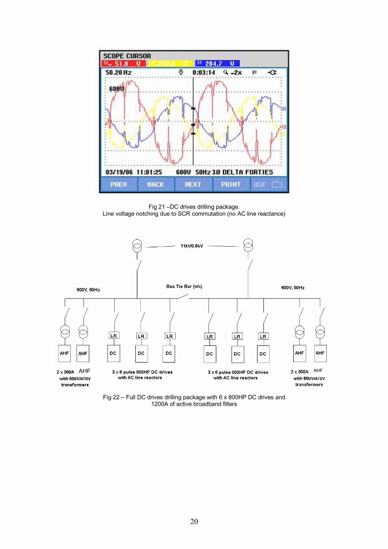
The operator decided to redesign the power generation and supply system on the recently acquired oilfield in order to save a significant amount of operating costs on the fuel used to power the diesel generators. The original oilfield power design had four platforms, A, B, C and D. All had onboard generating capacity. A fifth satellite platform (E) was supplied from both platforms A and D at 11kV. The majority of the platforms had been in operation for a number of years with no obvious harmonics problems. The new design called for the removal of all diesel generators and the installation of large gas turbine generators on two of the platforms. A ring main was installed to supply all five platforms with power. Due to the distances between platforms and other issues, 33kV was used as the transmission voltage. Each platform has 33kV/11kV transformers to supply the respective power systems. During a detailed study of the revised system the consultants calculated that due to the 33kV cable capacitive reactance when the ring main was closed, resonance was possible between 250 and 550 hertz (Hz) on this 50 Hz system, also identified as between the 5th to 11th harmonic orders. Additionally, the resonant frequency would vary within that bandwidth according to operating conditions. Clearly the harmonic currents within this frequency band had to be significantly reduced in order to minimise the possibility of resonance. A number of harmonic related issues were discovered. One example being the THDv on a number of platforms at the 600 VAC distribution bus was close to 25%. This exceeds all reasonable safe levels for all harmonic standards around the world not to mention the resultant heating of the generator and fixed speed motors windings (including explosion proof motors) and the voltage distortion seen at the functioning levels for all connected platforms. The voltage harmonics illustrated in Fig 20 were measured on a sister platform of identical design. The harmonic voltage spectrum on this sister platform was due to 4800HP of 6 pulse DC SCR drilling running at 90% load and a large number of AC drives including 12 pulse, 18 pulse, 24 pulse and active front end (AFE) AC drives on electrical submersible pumps (ESPs). With the exception of those associated with the 4800HP 600V DC SCR drive package, all the harmonics originate from the 11kV bus and appear on the 600V as ‘background distortion’. The voltage waveforms of the DC drive drilling package were also captured as illustrated in Fig 21. The voltage notches tending towards zero indicated the absence of any AC line reactance installed on the DC drives. On platforms and drilling rigs the lack of AC line reactors usually results in voltage spikes that can damage the capacitors in smaller AC variable frequency drives (VFDs), as well as, cause other SCR rectifiers to fault. This problem is often exacerbated by the use of EMC filters due to the high frequency nature of the line notches. Other sensitive equipment can also be damaged or disrupted. AC line reactors with 3% or more impedance were specified for Platform C and other future
installations to reduce the notching to an acceptable level. THE SOLUTION The 4800HP 600V DC SCR drilling package (plus the 900HP AC VFD Top Drive) presented the largest discrete 6 pulse non linear loads and were selected as the first step in reducing the platforms harmonic footprint. After considering a number of harmonic mitigation technologies, broadband type active filters were selected for the following reasons:
• Speed of operation (100µS); real time performance.
• All non fundamental currents treated (not just characteristic harmonics).
• Significant further reduction in line notching claimed by manufacturer.
The general schematic of the 4800HP DC SCR drilling package (excluding the 900HP AC VFD Top Drive) with the broadband active filters is illustrated in Fig 22. As can be seen 2 x 300A active filters connected in parallel were installed on each side of the busbar. The 900HP AC VFD Top Drive has a 300A active connected to it. Trend recording was in operation during the commissioning. Figs 23 through Fig 25 illustrate the salient measurements. Of particular significance are the reductions of the 5th harmonic current amplitude (Fig 25) from 232 amperes to 11 amperes and the 7th harmonic current amplitude from 72 amperes to 11 amperes as well. This was the particular area of concern outlined by the consultants report with respect to resonance potential. During the commissioning of the drilling package, the 11kV supplies were monitored by a third party. They reported that without the 50% drilling package operating (i.e. 3 x 800HP DC drives) the background THDv at 11kV was 4.2% rising to 4.8% when this 50% of the drilling package DC drives was running. Once the active filter was switched on they reported the 11kV THDv dropped to 4.1%. The effect of the active filter was therefore to reduce the net contribution of the 3 x 800HP DC drives to around zero. Had the full drilling package been running (i.e. 6 x 800HP) the full contribution to the 11kV would have been in the order of 1.2%, which represents some 25% of all distortion on the 11kV supplies. The installation of the active harmonic filters reduces that to almost zero. In addition, due to the excellent response of active harmonic filter (100uS) the line notching was almost eliminated as can be seen in Fig 26. We look forward to installing broadband active filters on the other drilling packages and on the 11kV supplies (via special transformers) in order to drive down voltage distortion for the generator and the rest of the ring main system. Only by doing so will the operator of the oil field have low voltage distortion in the 33kV subsea cables, thus reducing harmonics and the potential for resonance with the resulting problems associated with each.

7
SUMMARY The four case studies discussed demonstrate the complex nature of the applications. Each required cycle by cycle management of the current harmonics and/or reactive current. The quarry crusher application required elimination of in-rush currents for AC motors in microseconds to avoid flicker in the plant and on the utility. This type of performance can only be provided by real-time broadband active filters. The broadband active
filter does not waste time defining the harmonic orders. It assumes any current other than the fundamental current is to be eliminated from the source current and performs that action in steady state loads within the cycle and for step load changes in microseconds. Please ensure that the active filter you select for your application is suitable in all aspects for the tasks in hand. As has been illustrated in these case studies ‘there are active filters and there are active filters!’

8
Fig. 1 - Simplified power circuit of broadband active filter
Fig 2 - Block diagram of typical shunt connected broadband active filter with associated current waveforms

9
Fig 3 – Dutch offshore oil platform simplified diagram after downsizing

10
.
Fig 4a - K4 ESP THDv without/with active filter
Fig 4b - K4 ESP THDi without/with active filter
Fig 4c - K4 ESP DPF without/with active filter

11
Fig 5 – Cone crusher with 315kW induction motor with active filter
-350.0-300.0-250.0-200.0-150.0-100.0-50.000.00050.00100.0150.0200.0250.0300.0350.0
V
10:30:06.57628/03/2006
10:30:06.65628/03/2006
16 mSec/Div80.225 (mS)
Fig 6 - Transient phase voltages at instance of start up of 315kW motor. Voltage reduced from 240V to 178V-185V which reduces torque of motor

12
-3.000E+3-2.500E+3-2.000E+3-1.500E+3
-1000-500.00.000500.01000
1.500E+32.000E+32.500E+3
A
10:30:06.57628/03/2006
10:30:06.65628/03/2006
16 mSec/Div80.225 (mS)
Fig 7 – Transient phase currents at start up of 315kW crusher motor. Currents were 2085A rms maximum over starting period
1.000
1.500
2.000
2.500
3.000
3.500
4.000
12:05:00.00028/03/2006
12:19:41.00028/03/2006
2 Min/Div14:41.000 (M:S)
Fig 8 - Flicker over duration of production run on generator supplies (400V) on primary crusher
Trendline Time Min Vflk Avg Vflk Max Vflk ---V1
ESB Test at 10kV
12:05-12:20 1.1
0.201
2.52
1.038
3.36
3.886 ---V2
ESB Test at 10kV
12:05-12:20 1.25
0.197
2.96
1.078
3.9
4.008 ---V3
ESB Test at 10kV
12:05-12:20 0.92
0.197
1.86
1.064
2.53
3.993
Table 1 – Data to accompany Fig 8 plus power company (ESB) test data (at 10kV) for comparison

13
45.0050.0055.0060.0065.0070.0075.0080.0085.0090.0095.00100.0105.0110.0115.0
k W
12:05:00.00028/03/2006
12:19:41.00028/03/2006
2 Min/Div14:41.000 (M:S)
45.0050.0055.0060.0065.0070.0075.0080.0085.0090.0095.00100.0105.0110.0115.0
k W
12:05:00.00028/03/2006
12:19:41.00028/03/2006
2 Min/Div14:41.000 (M:S)
Fig 9 – Active power (kW) per phase recorded during tests
Trendline Time Min kW Avg kW Max kW ---L1 12:05-12:20 51.25 81.56 105.80 ---L2 12:05-12:20 48.59 78.81 102.80 ---L3 12:05-12:20 48.57 76.18 99.35
Sum of phases 12:05-12:20 148.39 236.45 307.95
Table 2 – Active power per phase during measurements
65.0070.0075.0080.0085.0090.0095.00100.0105.0110.0115.0120.0125.0130.0
k VAR
12:05:00.00028/03/2006
12:19:41.00028/03/2006
2 Min/Div14:41.000 (M:S)
65.0070.0075.0080.0085.0090.0095.00100.0105.0110.0115.0120.0125.0130.0
k VAR
12:05:00.00028/03/2006
12:19:41.00028/03/2006
2 Min/Div14:41.000 (M:S)
Fig 10 – Reactive power (kVAr) recorded during tests
Trendline Time Min kVAr Avg kVAr Max kVAr ---L1 12:05-12:20 78.33 91.69 117.97 ---L2 12:05-12:20 79.04 92.91 119.20 ---L3 12:05-12:20 71.45 84.09 108.34
Sum of phases 12:05-12:20 228.82 268.69 345.51
Table 3 – Reactive power (kVAr) per phase during measurement period

14
Fig 11 – Secondary crusher (200kW motor) in foreground. Primary unit is in the right background
350.0355.0360.0365.0370.0375.0380.0385.0390.0395.0400.0405.0410.0415.0420.0425.0430.0435.0
V
17:05:00.00015/03/2007
17:34:57.00015/03/2007
5 Min/Div29:57.000 (M:S)
350.0355.0360.0365.0370.0375.0380.0385.0390.0395.0400.0405.0410.0415.0420.0425.0430.0435.0
V
17:05:00.00015/03/2007
17:34:57.00015/03/2007
5 Min/Div29:57.000 (M:S)
Fig 12 - Generator voltage without/with/without treatment

15
Fig 13 - Current drawn from the generator by primary crusher without/with/without treatment
10.0015.0020.0025.0030.0035.0040.0045.0050.0055.0060.0065.0070.0075.0080.0085.0090.00
k VAR
17:05:00.00015/03/2007
17:34:57.00015/03/2007
5 Min/Div29:57.000 (M:S)
10.0015.0020.0025.0030.0035.0040.0045.0050.0055.0060.0065.0070.0075.0080.0085.0090.00
k VAR
17:05:00.00015/03/2007
17:34:57.00015/03/2007
5 Min/Div29:57.000 (M:S)
Fig 14 - kVAr demand on the generator by primary crusher without/with/without treatment
0.4500.500
0.5500.600
0.6500.700
0.7500.800
0.850
0.9000.950
1.0001.050
17:05:00.00015/03/2007
17:34:57.00015/03/2007
5 Min/Div29:57.000 (M:S)
0.4500.500
0.5500.600
0.6500.700
0.7500.800
0.850
0.9000.950
1.0001.050
17:05:00.00015/03/2007
17:34:57.00015/03/2007
5 Min/Div29:57.000 (M:S)
Fig 15 - Displacement power factor of primary crusher without/with/without treatment
Active filter
Active filter Active filter

16
0.600
0.800
1.000
1.200
1.400
1.600
17:05:00.00015/03/2007
17:34:57.00015/03/2007
5 Min/Div29:57.000 (M:S)
0.600
0.800
1.000
1.200
1.400
1.600
17:05:00.00015/03/2007
17:34:57.00015/03/2007
5 Min/Div29:57.000 (M:S)
Fig 16 - Flicker (Pst) on generator (due to primary and secondary crushers) including for 33% of the time when NO treatment for flicker operating
Trendline Date Min Vflk Avg Vflk Max Vflk ---V1
Primary
crusher – no treatment
Primary and
secy crushers after
treatment
28/03/06
15/03/07
1.1
0.66
2.52
0.83
3.36
1.58
---V2
Primary crusher – no
treatment
Primary and secy crushers
after treatment
28/03/06
15/03/07
1.25
0.63
2.96
0.79
4.008
1.50
---V3
Primary crusher – no
treatment
Primary and sexy crushers
after treatment
28/03/06
15/03/07
0.92
0.66
1.86
0.89
2.53
1.52
Table 4 – Comparison flicker result on primary crushers without treatment and both
primary and secondary crushers with treatment. Note that for treatment results the flicker was recorded for a period of 33% where no treatment was connected !

17
2 x 5MVA 11:22 kV XFMRS
Utility 11kV
22kV
17.5 km
MES
5E switchboard
22kV
5 Gantry cranes
Fig 17 – Simplified Electrical One Line Drawing

18
6-pulse rectifier
Transformer 2000 kVA 22 kV
4 x 175 kVAR Tuned 5th Filter
DC drive
DC Hoist Motor # 1 630kW
6-pulse rectifier
DC/AC Inverter
Gantry Motor Group #1 8 x 18.5kW AC Motors
Trolley Motor Group #1 2 x 90kW AC Motors
Gantry Motor Group #2 8 x 18.5kW AC Motors
Trolley Motor Group #2 2 x 90kW AC Motors
1800kVA 22/0.48kV Dyn0
200kVA22/0.4kV Dyn0
Crane utilities
DC Hoist Motor # 2 630kW
Analyzer measuring point
Fig 18 – Electrical One-line of Crane
DC/AC Inverter
DC/AC Inverter
DC/AC Inverter
DC drive

19
Fig 19 –Distortion levels upon activation of harmonic filter (at 14:54hrs). Higher than expected THDv due to background voltage distortion on system.
Fig 20 – Voltage harmonics on 600V bus. Note the THDv is greater above the 23rd then below. Overall THDv were 24.3%
(L1), 23.9% (L2) and 23.4% (L3).
20
Fig 21 –DC drives drilling package. Line voltage notching due to SCR commutation (no AC line reactance)
Fig 22 – Full DC drives drilling package with 6 x 800HP DC drives and
1200A of active broadband filters
AHF AHF

21
0.000
5.000
10.00
15.00
20.00
25.00
30.00
35.00
40.00
45.00
50.00
%
16:30:00.00014/07/2006
16:51:20.00014/07/2006
4 Min/Div21:20.000 (M:S)
0.000
5.000
10.00
15.00
20.00
25.00
30.00
35.00
40.00
45.00
50.00
%
16:30:00.00014/07/2006
16:51:20.00014/07/2006
4 Min/Div21:20.000 (M:S)
Fig 23 – THDi on 3 x 800HP DC drives without/with/without broadband active filter. THDi reduced from 35% to 3.7%.
2.000
4.000
6.000
8.000
10.00
%
16:30:00.00014/07/2006
16:51:20.00014/07/2006
4 Min/Div21:20.000 (M:S)
2.000
4.000
6.000
8.000
10.00
%
16:30:00.00014/07/2006
16:51:20.00014/07/2006
4 Min/Div21:20.000 (M:S)
Fig 24 - THDv on 3 x 800HP DC drives without/with/without active harmonic filter. THDv reduced from 11.2% to 3.7%.
0.000
50.00
100.0
150.0
200.0
250.0
A
16:30:00.00014/07/2006
16:51:20.00014/07/2006
4 Min/Div21:20.000 (M:S)
0.000
50.00
100.0
150.0
200.0
250.0
A
16:30:00.00014/07/2006
16:51:20.00014/07/2006
4 Min/Div21:20.000 (M:S)
Fig 25 - Salient harmonics: -- 5th, --7th, --- 11th, --- 13th on 3 x 800HP DC drives
without/with/without active harmonic filter. Note - 5th harmonic reduced from 232A to 11A.

22
Fig 26 – 3 x 800HP DC drives voltage waveforms and THDv with active harmonic filter (2.6% THDv). Note vast improvement in line notching due to broadband active filter real-time response
Authors: Ian C Evans Following a background in marine and offshore electrical engineering and thirteen years in the drives industry as founder and Managing Director of Elektrotek Drives Limited and Managing Partner of Howieson & Evans, Drive Consultants, Mr. Evans has been heavily involved in harmonic mitigation following his early 1997 introduction of active filters into the European and Middle Eastern market marketplace. Mr. Evans is currently Managing Director of Harmonic Solutions Co.Uk Ltd, a specialist company providing innovative passive and active harmonic mitigation solutions, specialist technical training and harmonic consultancy services around the world for industrial, marine and offshore clients. He has written numerous editorials and papers on AC drives, explosion proof motor/VFD interaction, electric propulsion, harmonics and associated issues and in 2005 wrote the 240 page harmonics guidance notes for a major international marine classification body.
James R. Johnson is a 1972 graduate of the University of Pittsburgh with a Bachelor of Science degree in Electrical Engineering. His experience includes 21 years of selling, applying, and servicing AC & DC motor speed controls with several companies including Robicon, Emerson Industrial Controls, and Control Techniques. Beginning in 1983, Jim worked extensively in providing harmonic mitigation equipment in conjunction with motor speed controls. Since 1993, he has worked exclusively in the power quality market specializing in power factor correction and harmonic mitigation equipment, with major emphasis on active harmonic filters. Jim has lead two companies into the active harmonic filter market via company start-ups. Jim is presently Product Marketing Manager for AccuSine products for the PQ Correction Group of Schneider Electric – North America. Jim is a member of IEEE.