
Prachi Chitnis Raja Ramanna Centre for Advanced Technology Indore, INDIA.
31
EPICS Based Control System for Microtron at RRCAT, Indore Prachi Chitnis Raja Ramanna Centre for Advanced Technology Indore, INDIA
-
Upload
beverly-short -
Category
Documents
-
view
229 -
download
1
Transcript of Prachi Chitnis Raja Ramanna Centre for Advanced Technology Indore, INDIA.
EPICS Based Control System for Microtron at
RRCAT, IndorePrachi Chitnis
Raja Ramanna Centre for Advanced TechnologyIndore, INDIA
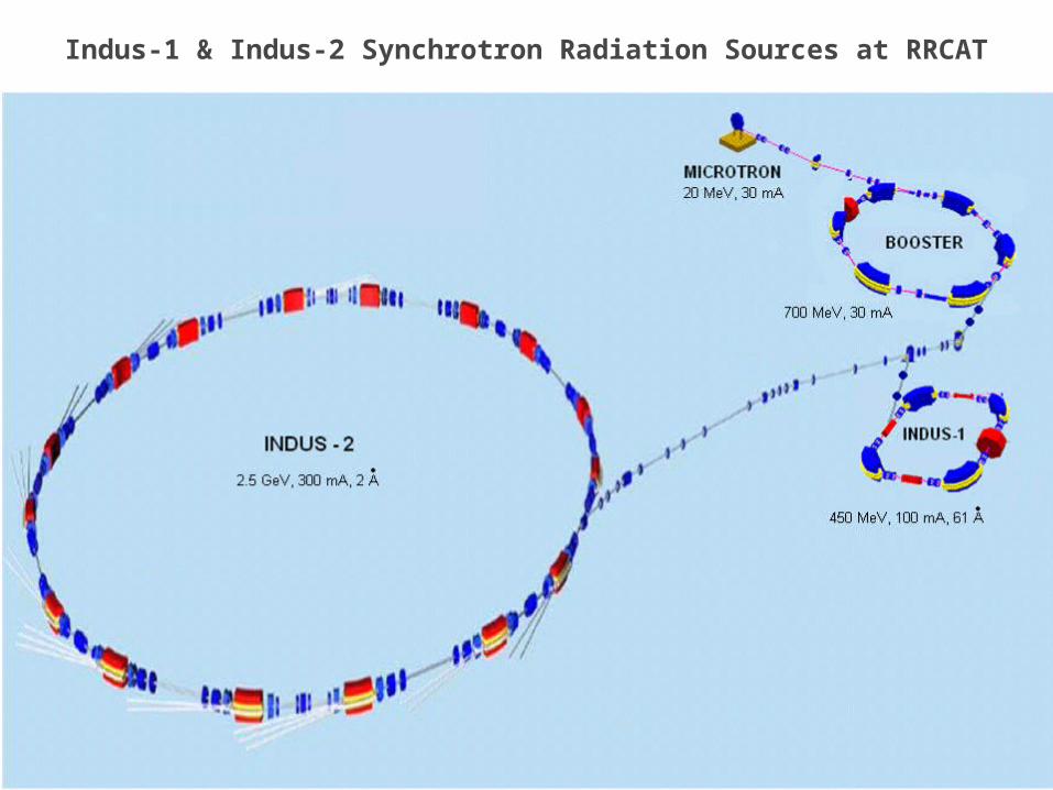
Indus-1 & Indus-2 Synchrotron Radiation Sources at RRCAT

Injector System of Indus Rings
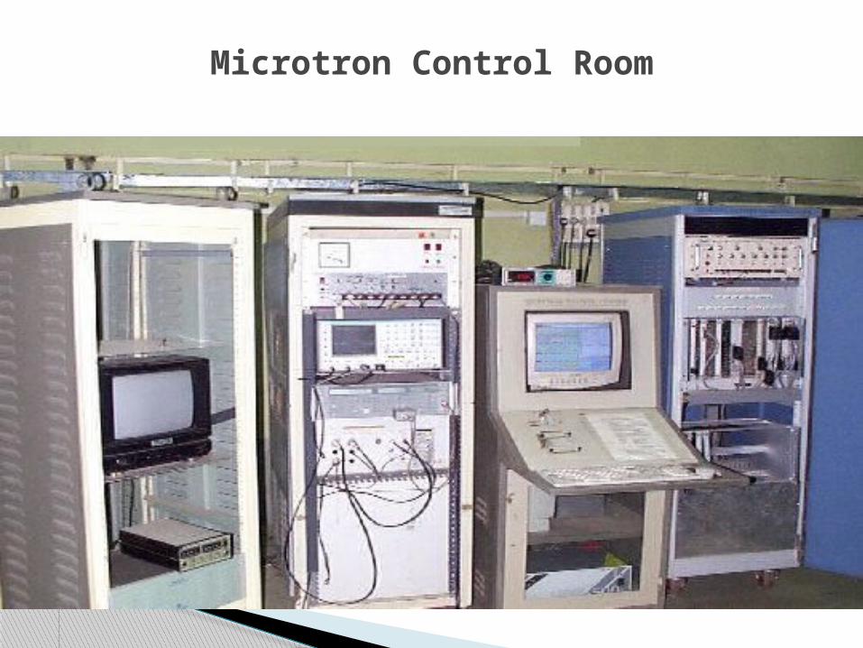
Microtron Control Room
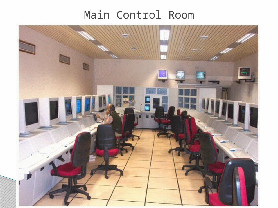
Main Control Room
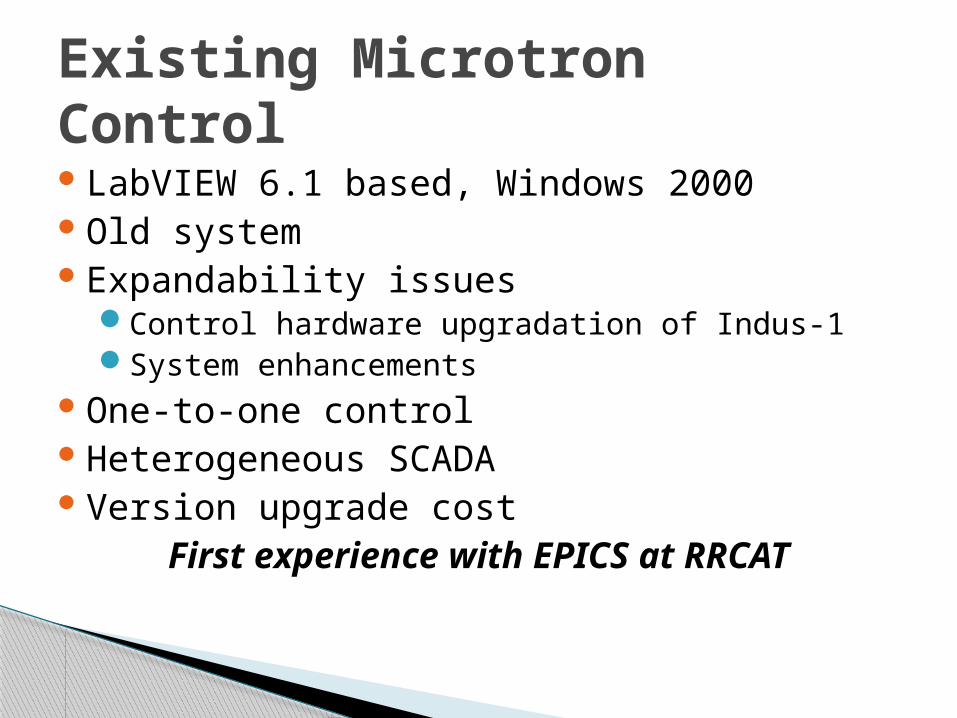
LabVIEW 6.1 based, Windows 2000Old system Expandability issues
Control hardware upgradation of Indus-1System enhancements
One-to-one controlHeterogeneous SCADAVersion upgrade cost
First experience with EPICS at RRCAT
Existing Microtron Control
June '09M.Tech. Project Progress
Review Seminar 7
Microtron Control System Design

Microtron Control Scheme
10 Mbps
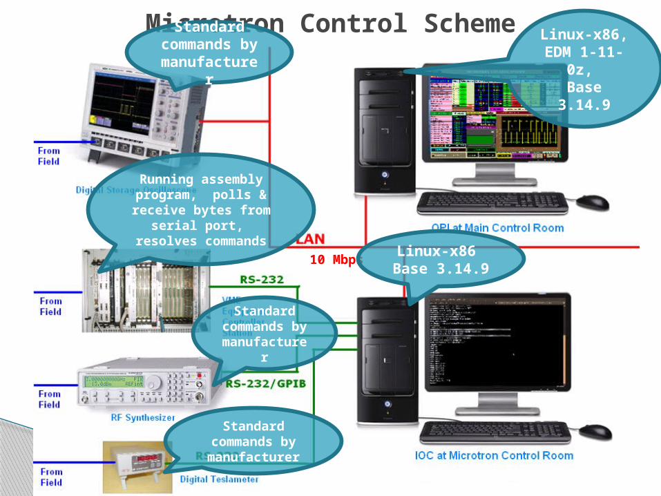
Microtron Control Scheme
Running assembly program, polls &
receive bytes from serial port,
resolves commands
Standard commands
by manufactur
er
Standard commands
by manufactur
er
Standard commands by manufacturer
10 Mbps
Linux-x86, EDM 1-11-0z, Base 3.14.9
Linux-x86 Base 3.14.9
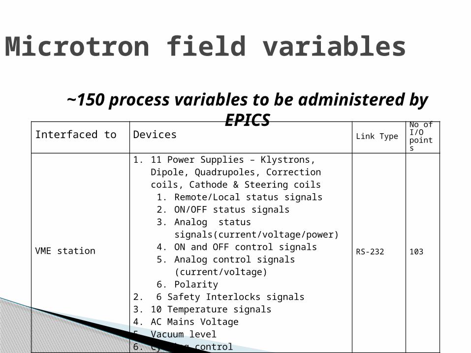
Microtron field variables
Interfaced to Devices Link TypeNo of I/O points
VME station
1. 11 Power Supplies – Klystrons, Dipole, Quadrupoles, Correction coils, Cathode & Steering coils
1. Remote/Local status signals2. ON/OFF status signals3. Analog status
signals(current/voltage/power)4. ON and OFF control signals5. Analog control signals (current/voltage)6. Polarity
2. 6 Safety Interlocks signals3. 10 Temperature signals4. AC Mains Voltage5. Vacuum level6. Cycling control
RS-232 103
~150 process variables to be administered by EPICS
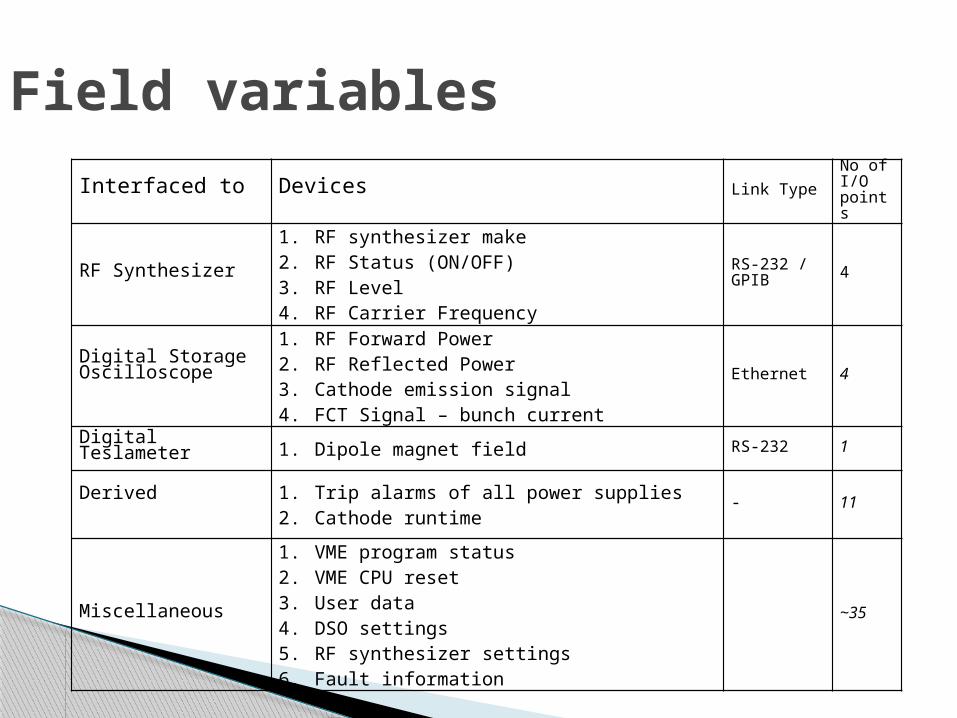
Field variablesInterfaced to Devices Link Type
No of I/O points
RF Synthesizer
1. RF synthesizer make2. RF Status (ON/OFF)3. RF Level4. RF Carrier Frequency
RS-232 / GPIB 4
Digital Storage Oscilloscope
1. RF Forward Power 2. RF Reflected Power3. Cathode emission signal4. FCT Signal – bunch current
Ethernet 4
Digital Teslameter 1. Dipole magnet field RS-232 1
Derived 1. Trip alarms of all power supplies2. Cathode runtime
- 11
Miscellaneous
1. VME program status2. VME CPU reset3. User data4. DSO settings5. RF synthesizer settings6. Fault information
~35
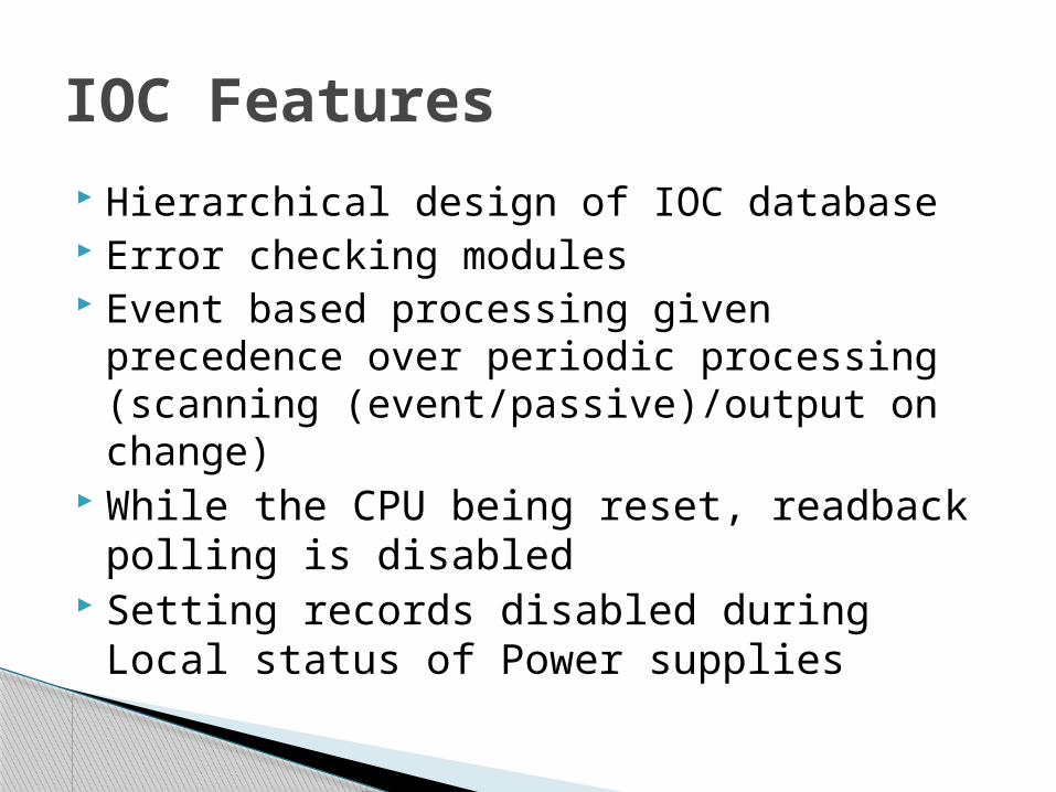
Hierarchical design of IOC database Error checking modules Event based processing given precedence
over periodic processing (scanning (event/passive)/output on change)
While the CPU being reset, readback polling is disabled
Setting records disabled during Local status of Power supplies
IOC Features
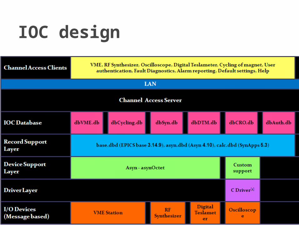
IOC design

User Authentication
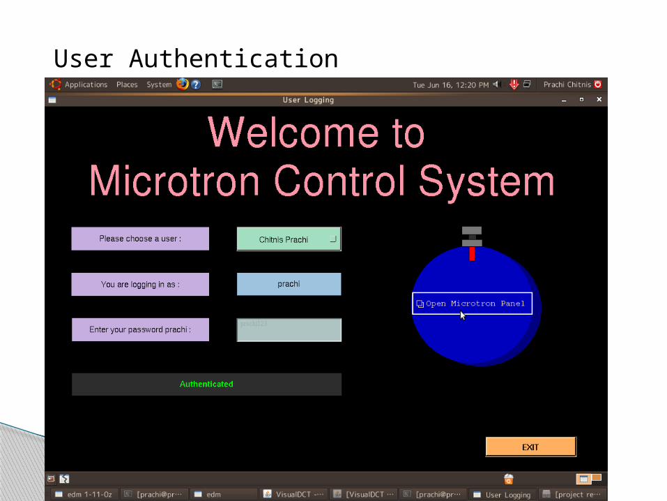
User Authentication
16
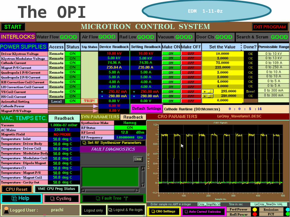
The OPI EDM 1-11-0z

17
The OPI EDM 1-11-0z – MEDM – client commands in terminal
VME
RF Syn
DSO
DTM
18
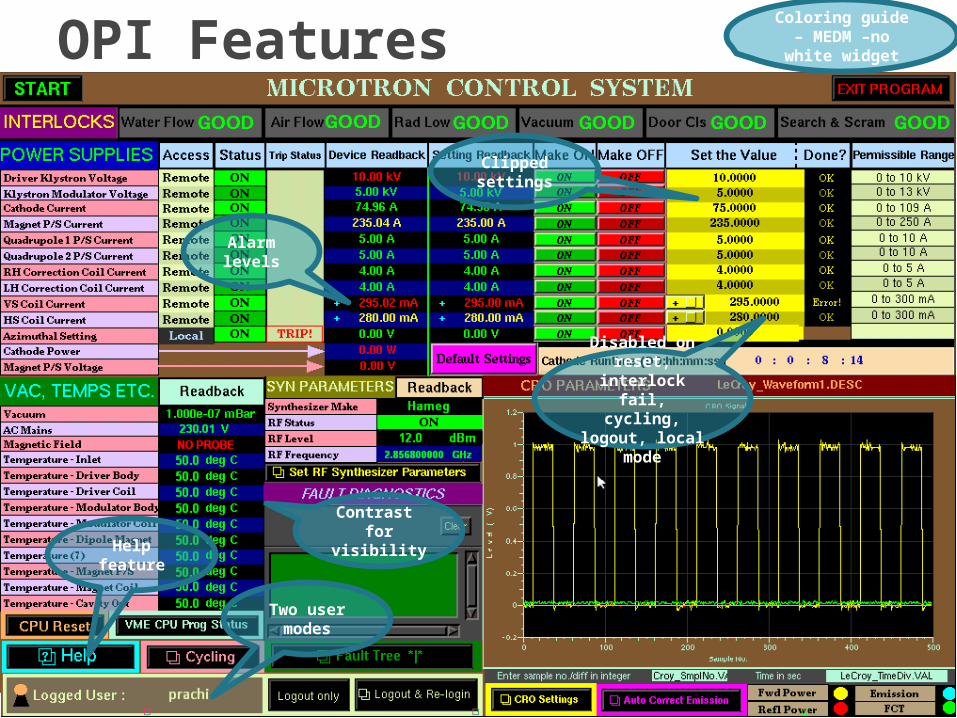
OPI Features Coloring guide
– MEDM –no white widget
Alarm levels
Contrast for
visibility
Disabled on reset, interlock
fail, cycling, logout, local
mode
Two user modes
Clipped settings
Help feature
19
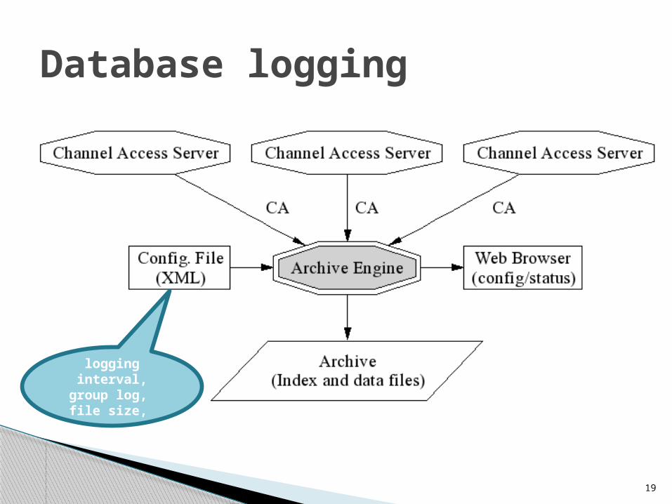
Database logging
logging interval, group log, file
size,
20
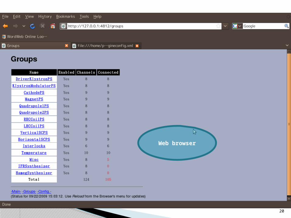
Web browser
Central database for Indus systems – SQL server based
Using JCA Java script and JDBC
Database logging
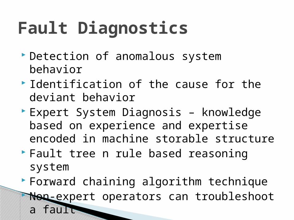
Detection of anomalous system behavior Identification of the cause for the deviant
behavior Expert System Diagnosis – knowledge
based on experience and expertise encoded in machine storable structure
Fault tree n rule based reasoning system Forward chaining algorithm technique Non-expert operators can troubleshoot a
fault
Fault Diagnostics
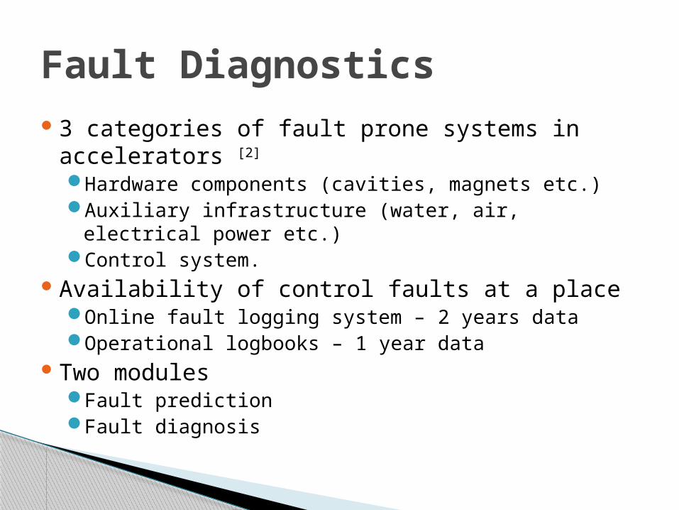
3 categories of fault prone systems in accelerators [2]
Hardware components (cavities, magnets etc.)Auxiliary infrastructure (water, air, electrical power
etc.)Control system.
Availability of control faults at a placeOnline fault logging system – 2 years dataOperational logbooks – 1 year data
Two modulesFault predictionFault diagnosis
Fault Diagnostics
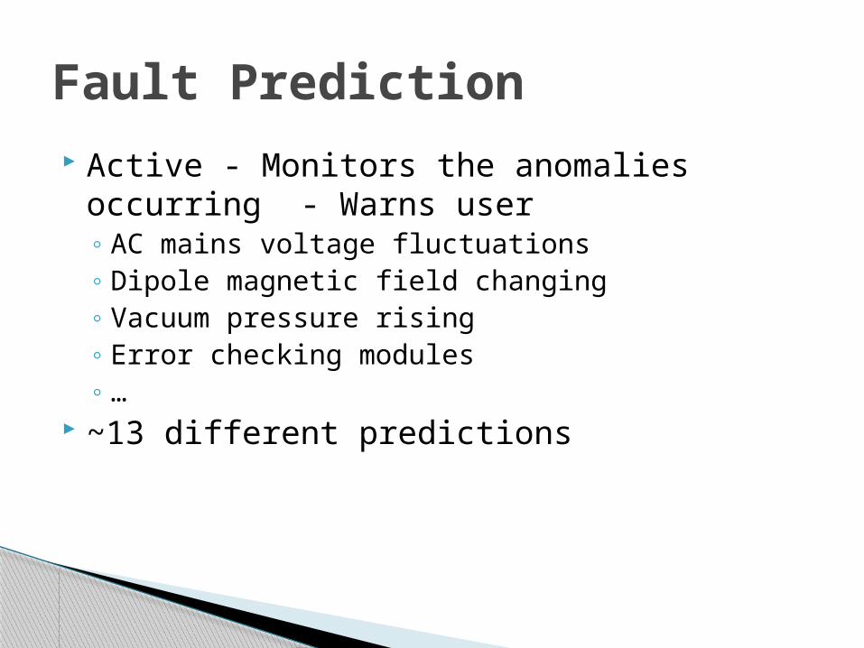
Active - Monitors the anomalies occurring - Warns user◦ AC mains voltage fluctuations◦ Dipole magnetic field changing◦ Vacuum pressure rising◦ Error checking modules◦ …
~13 different predictions
Fault Prediction
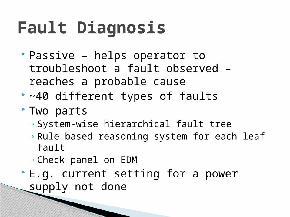
Passive – helps operator to troubleshoot a fault observed – reaches a probable cause
~40 different types of faults Two parts
◦ System-wise hierarchical fault tree◦ Rule based reasoning system for each leaf fault◦ Check panel on EDM
E.g. current setting for a power supply not done
Fault Diagnosis
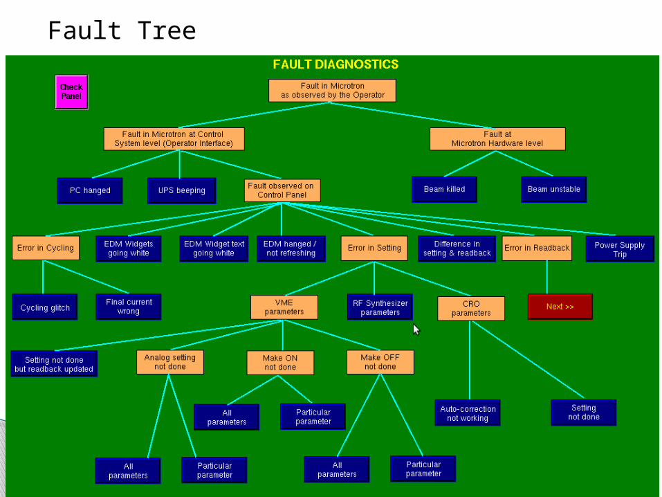
Fault Tree
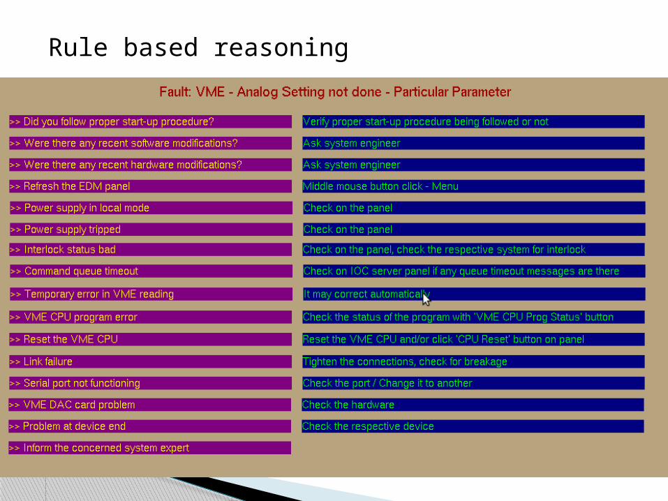
Rule based reasoning
Interaction between controllers – Access to PVs
Integration of Indus-1 controls Homogeneous system Accelerator specific tools Free n open source Modularity – suits to control hardware
upgradation of Indus-1 Huge EPICS community
Improvements achieved by using EPICS
The testing of the project is done in lab environment, field testing is on
Due to its easy adaptability to hardware changes, EPICS is best suited prospective to hardware upgradation.
Mostly involves graphical programming, eases enhancements and changes, and debugging.
The knowledge gained will be utilized for upgrading the Indus-1 control systems.
Conclusion
[1]http://optics.eee.nottingham.ac.uk/lecroy_tcp/driver_source/tarballs/lecroy_tcp-1.00.tar.gz
[2] Basis for the reliability analysis of the proton linac for an ADS program - D. Barni et. al. - Proceedings of the PAC ’03
[3] http://www.aps.anl.gov/epics/ [4] Fault identification in accelerator control - Philip
Duval et.al. DESY, Germany[5] Availability and reliability issues for ILC - T. Himel
et.al. - Proceedings of PAC’07[6] Automated diagnosis of physical systems - S.
Narasimhan et.al. - Proceedings of ICALEPCS07
References

Thank You!


![arXiv:2007.07326v1 [astro-ph.IM] 14 Jul 2020 Raja Ramanna ...](https://static.fdocuments.in/doc/165x107/61f1c64fb84b8562db2d2c50/arxiv200707326v1-astro-phim-14-jul-2020-raja-ramanna-.jpg)


