PQC - STATCON The ultra fast Power Quality Compensator · 4 PQC STATCON | Product brochure Features...
8
PQC - STATCON The ultra fast Power Quality Compensator
-
Upload
doannguyet -
Category
Documents
-
view
240 -
download
2
Transcript of PQC - STATCON The ultra fast Power Quality Compensator · 4 PQC STATCON | Product brochure Features...
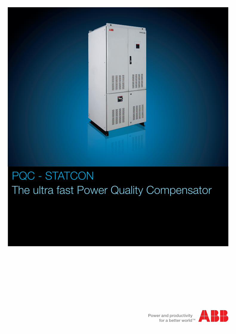
PQC - STATCONThe ultra fast Power Quality Compensator

2 PQC STATCON | Product brochure
PQC - STATCONThe ultra fast power quality compensator
Yellow - STATCON currentBlue - Supply VoltageMagenta - Step response
Figure 2: PQC - STATCON – Dynamic response
PQC - STATCON can perform a fast dynamic step change from 100% inductive VAr to 100% capacitive VAr or vice-versa in 1 -1.5 power cycles. Fig 2 shows a similar step response of PQC - STATCON with a recorded response rise time of 20.97 mS. Unlike capacitor based reactive power compensation systems, PQC - STATCON can be operated even in highly distorted voltage networks.
PQC - STATCON is based on IGBT voltage source inverter technology. It is a shunt connected device capable of performing ultra fast dynamic reactive power and unbalance compensation in a smooth step-less fashion. It uses a full closed loop control system to precisely control, regulate and improve the source power quality parameters.
PQC - STATCON technology is used for dynamic reactive power compensation, unbalance compensation and voltage stability improvement. Hence it has a wider application, even for the weaker networks. Apart from the grid supply network, it can support dynamic loads operating from generator. PQC - STATCON has a good steady state performance with much faster response and superior control characteristics. It can be operated dynamically to compensate to fast varying capacitive, inductive and unbalanced loads. A typical PQC - STATCON installation is shown in Figure 1.
PQC - STATCON supplies the reactive and unbalance components of load currents locally. Therefore the PCC and source are relieved from the excessive VAr loading. The source supplies only clean real power and the heating of equipment are reduced, improving the life of plant electrical infrastructure.
Figure 1: A typical PQC - STATCON installation
Source Load
PQC STATCON
Real power Unbalance / reactive power

PQC - STATCON variants
PQC - STATCON is available for single phase and three phase applications as PQCS STATCON and PQCT STATCON respectively.
The PQCS STATCON performs fast reactive power compensation based on a target power factor (PF) setting, which can programmed through the user interface. PQCS STATCON also has an option for setting dual PF target (Main/ Auxiliary PF Targets). This option enables the system to work at unity PF (or any other Main PF setting), when supplied from utility source and to work at 0.8 lag PF (or any other Auxiliary PF setting), when supplied from generator. PQCS STATCON is well suited for single phase applications like railway traction substations and automotive welding shops.
The PQCT STATCON performs fast reactive power and unbalance compensation for a three phase network. The operation of PQCT STATCON is represented in Figure 3.
PQCT STATCON has priority option to perform allocate the converter resources between reactive power and unbalance compensation requirements, in addition to the dual PF target option as in PQCS STATCON. The Priority compensation can be selected to be Reactive Power or Unbalance. If reactive power is selected as priority, PQC - STATCON will compensate for reactive power to the specified target PF and use the remaining resources for unbalance compensation. If unbalance is selected as priority, PQC - STATCON will nullify the unbalance current components in the load and use the available remaining resources for reactive power compensation. In addition to priority setting, the dual PF target option enables the system to work at unity PF (or any other Main PF setting), when supplied from utility source and to work at 0.8 lag PF (or any other Auxiliary PF setting), when supplied from generator.
Figure 3: PQCT STATCON nullifies the reactive & unbalance currents at the source Note: PQCT STATCON is a three wire device. It compensates the phase to phase unbalance currents only.
Product brochure | PQC STATCON 3
Real current Reactive current Negative sequence unbalance current
Reactive current Negative sequence unbalance current Real current
PQCT STATCON current Source current
Load current
+ +
Real Current Reactive Current Negative Sequence
Unbalance Current
+
Negative Sequence
Unbalance Current
Reactive Current
Real Current
+
+ +
(–)
Load current (-) PQCT STATCON current = Source current

4 PQC STATCON | Product brochure
Features
PQC STATCON is an advanced, reliable and user friendly solution for power quality problems. It uses robust control and protection techniques implemented on a high speed digital control system. The features of PQC STATCON are discussed as follows.
Energy efficient operationEnergy save mode is a feature available in PQCS and PQCT range of PQC - STATCONs. If the PQC - STATCON is operating at near zero current levels for 30 seconds, IGBT converter is switched off and successively the blowers are switched off in 2 minutes. The system enters a sleep mode and the stress on power components is minimized. The power consumption of PQC - STATCON in sleep mode is almost zero, but the system is available in hot standby. As the load demand rises, the system can supply the rated kVAr within 5-8 power cycles.
This mode can be optionally enabled / disabled through the user interface.
Operation with parallel fixed capacitor bankPQC - STATCON has the capability to operate in inductive and capacitive modes. In order to achieve higher kVAr, PQC - STATCON may be operated in parallel with a fixed
capacitor bank. Refer figure 4.
PQC - STATCON can control the parallel filter banks through a potential free contact, by which energy efficient operation is achieved more efficiently and the system will achieve a dynamic range of -X to +2X kVAr.
ProtectionPQC - STATCON has advanced fault diagnostic features to provide a maximum protection level. It is protected against over-current, input supply over/under voltages, over-temperature, unstable grid and many more abnormal operating conditions. The diagnostic feature also monitors the performance of cooling system and any permanent failure of PQC - STATCON system components.
The fault history is recorded with time stamping and duration of the fault. The logged history is accessible through the graphical user interface (GUI).
100% 100% 200%
+ =
-100%
0%
0%
Figure 4: Improved economic dynamic range with parallel capacitor bank
Statcon Fixed capacitor Total RPC plant
x
-x
x 2 x

Product brochure | PQC STATCON 5
The different modes of PQC - STATCON operation are discussed as follows.
Fixed compensation mode In this mode PQC - STATCON supplies a fixed lagging / leading reactive current. It functions as a fixed inductive / capacitive reactive current source. The current to be supplied can be set through the user interface.
Dynamic modesIn dynamic modes PQC - STATCON supplies a dynamic current based on the feedback from CT. It can take feedback from CT located on the source side or load side.
Dynamic, load CT modeThis mode can be selected through the user interface. PQC - STATCON measures the reactive/unbalance component in load current and injects an anti-phase component of the same. Since both the currents are flowing on the same bus, the reactive/unbalance currents drawn by the load is locally compensated. This mode operates on an open loop fashion. When more than one PQC - STATCON are used in parallel, all of them uses the same CT feedback and shares the load demand equally. This mode is useful, when only the loads in a specific feeder are to be compensated and PQC - STATCON is located on a different feeder of the same bus.
Dynamic, grid CT modeThis mode can be selected through the user interface. In this mode PQC - STATCON measures and regulates the reactive/unbalance currents at the source side to zero. This is performed in a closed loop fashion. This is the most widely used, accurate and recommended method, by which the capabilities of PQC - STATCON can be utilized to the maximum. Typical configuration is shown in Figure 6.
In most cases more than one PQC - STATCON are used to meet the reactive power requirement. All the PQC - STATCON systems can share the same CT feedback and regulate the source power factor.
Modes of operation
Figure 5: Open loop configuration
Figure 6: Closed loop configuration
Figure 7: Operating boundaries of PQCT STATCON (Refer technical specifications - PQC Current for details)
ISTAT = (-ILq)
Ig = IL + ISTAT (-ILq)
Ig
IL = ILd, ILq
IL = ILd, ILq
ILISTAT = ILq + D
6 PQC STATCON | Product brochure
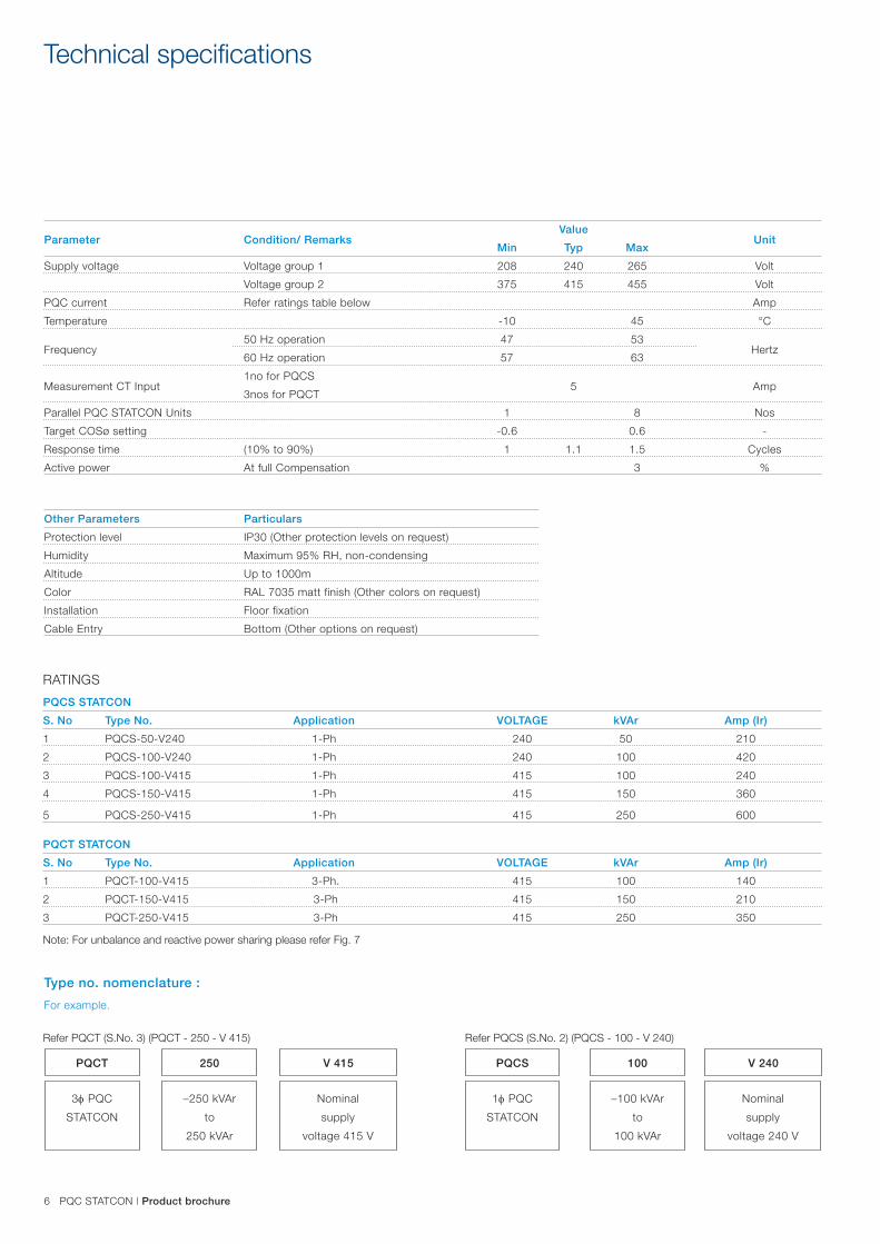
Technical specifications
Parameter Condition/ Remarks Value
Unit Min Typ Max
Supply voltage Voltage group 1 208 240 265 Volt
Voltage group 2 375 415 455 Volt
PQC current Refer ratings table below Amp
Temperature -10 45 °C
Frequency 50 Hz operation 47 53
Hertz 60 Hz operation 57 63
Measurement CT Input 1no for PQCS
5
Amp 3nos for PQCT
Parallel PQC STATCON Units 1 8 Nos
Target COSø setting -0.6 0.6 -
Response time (10% to 90%) 1 1.1 1.5 Cycles
Active power At full Compensation 3 %
Other Parameters Particulars
Protection level IP30 (Other protection levels on request)
Humidity Maximum 95% RH, non-condensing
Altitude Up to 1000m
Color RAL 7035 matt finish (Other colors on request)
Installation Floor fixation
Cable Entry Bottom (Other options on request)
RATINGS
PQCS STATCON
S. No Type No. Application VOLTAGE kVAr Amp (Ir)
1 PQCS-50-V240 1-Ph 240 50 210
2 PQCS-100-V240 1-Ph 240 100 420
3 PQCS-100-V415 1-Ph 415 100 240
4 PQCS-150-V415 1-Ph 415 150 360
5 PQCS-250-V415 1-Ph 415 250 600
PQCT STATCON
S. No Type No. Application VOLTAGE kVAr Amp (Ir)
1 PQCT-100-V415 3-Ph. 415 100 140
2 PQCT-150-V415 3-Ph 415 150 210
3 PQCT-250-V415 3-Ph 415 250 350
Type no. nomenclature :
For example.
PQCT PQCS250 100
3f PQC
STATCON
1f PQC
STATCON
–250 kVAr
to
250 kVAr
–100 kVAr
to
100 kVAr
Nominal
supply
voltage 415 V
Nominal
supply
voltage 240 V
V 415 V 240
Note: For unbalance and reactive power sharing please refer Fig. 7
Refer PQCT (S.No. 3) (PQCT - 250 - V 415) Refer PQCS (S.No. 2) (PQCS - 100 - V 240)
Product brochure | PQC STATCON 7
Applications
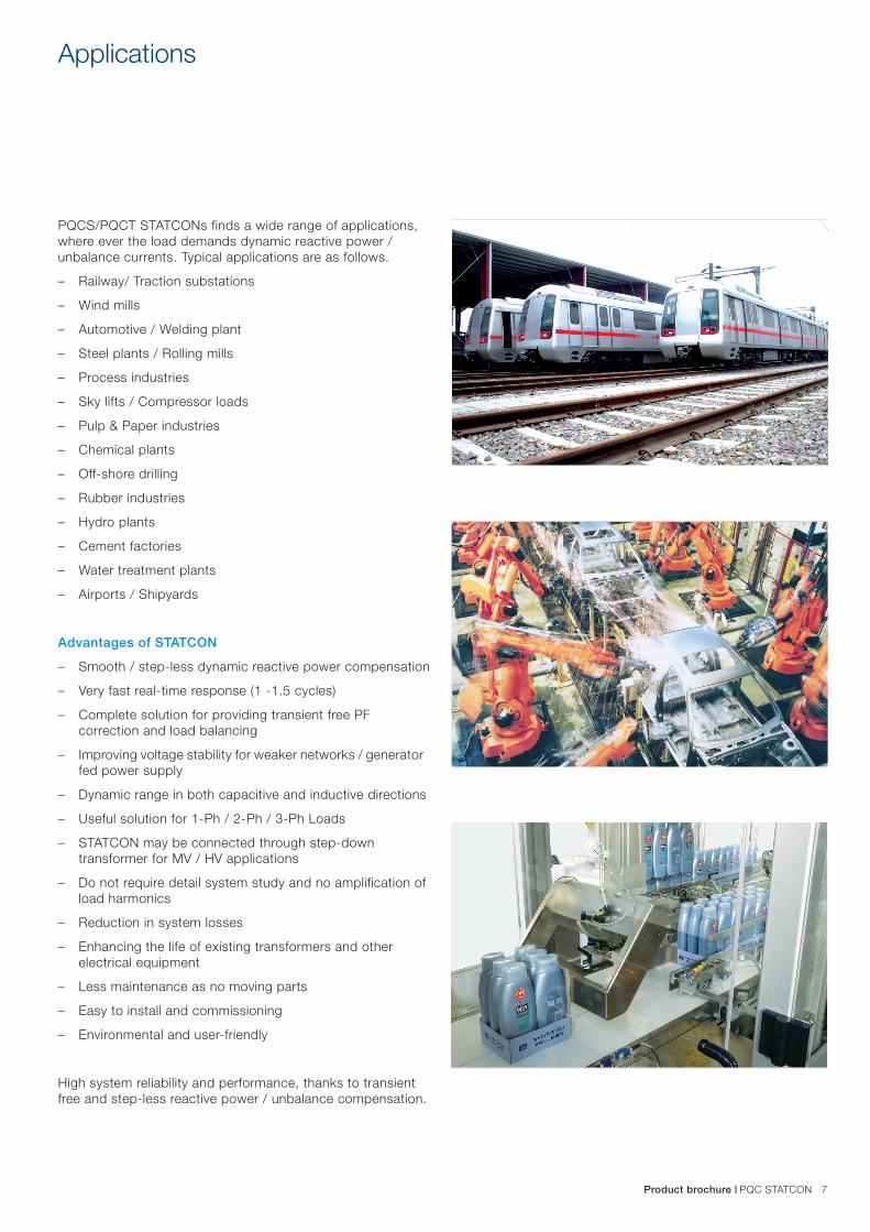
PQCS/PQCT STATCONs finds a wide range of applications, where ever the load demands dynamic reactive power / unbalance currents. Typical applications are as follows.
– Railway/ Traction substations
– Wind mills
– Automotive / Welding plant
– Steel plants / Rolling mills
– Process industries
– Sky lifts / Compressor loads
– Pulp & Paper industries
– Chemical plants
– Off-shore drilling
– Rubber industries
– Hydro plants
– Cement factories
– Water treatment plants
– Airports / Shipyards
Advantages of STATCON
– Smooth / step-less dynamic reactive power compensation
– Very fast real-time response (1 -1.5 cycles)
– Complete solution for providing transient free PF correction and load balancing
– Improving voltage stability for weaker networks / generator fed power supply
– Dynamic range in both capacitive and inductive directions
– Useful solution for 1-Ph / 2-Ph / 3-Ph Loads
– STATCON may be connected through step-down transformer for MV / HV applications
– Do not require detail system study and no amplification of load harmonics
– Reduction in system losses
– Enhancing the life of existing transformers and other electrical equipment
– Less maintenance as no moving parts
– Easy to install and commissioning
– Environmental and user-friendly
High system reliability and performance, thanks to transient free and step-less reactive power / unbalance compensation.

Contact us
© C
opyr
ight
200
9 A
BB
. All
right
s re
serv
ed. 1
HY
C41
2000
-300
NOTE: We reserve the right to make technical changes or modify the contents of this document without prior notice. With regard to purchase orders, the agreed particulars shall prevail. ABB does not accept any responsibility whatsoever for potential errors or possible lack of information in this document.
We reserve all rights in this document and in the subject matter and illustrations contained therein. Any reproduction, disclosure to third parties or utilization of its content - in whole or in parts - is forbidden without ABB’s prior written consent.
ABB LimitedPPHV - LV capacitorsPlot no. 5 & 6, 2nd phase, Peenya industrial area, Bangalore 560 058, India Phone: +91 80 2294 9334 / 9391 / 9330 Fax: +91 80 22949339
Email: [email protected]