Pqa 1 Oft ENGINEERING DATA TRANSMITTAL 615719/67531/metadc... · Humidity probe, 4-20 mA output...
27
Pqa 1 O f t 615719 ENGINEERING DATA TRANSMITTAL 2. To: (Receiving Organization) Distribution Characterization 5. Proj./Prog./Dept./Div.: 3. Frm: (Originating Organization) Analytical Services T. C. Schneider 6. Cog. Engr.: . 4. Related ED1 No.: N/A N/A 7. Purchase Order No.: 9. Equip./Component No.: N/A 10. System/Bldg./Facility: *Ig"L"re*l ?e IKI Signature ILI Date IMI MSlN 2006 11. Receiver Remarks: 12. Major Assm. Dug. No.: IG1 IHI Disp. son 13. Permit/Permit Application NO.: N/A 14. Required Response Date: 15. DATA TRANSMITTED (F) ApprovaI "PO, ription of Oata 4 If YFV 4/26/96 Rsanan Orid- Rscsiv- 80-7400-172-2 (04/94) GEF097
Transcript of Pqa 1 Oft ENGINEERING DATA TRANSMITTAL 615719/67531/metadc... · Humidity probe, 4-20 mA output...

P q a 1 O f t
6 1 5 7 1 9 ENGINEERING D A T A TRANSMITTAL
2. To: (Receiving Organization)
Distribution
Characterization 5 . Proj./Prog./Dept./Div.:
3. F r m : (Originating Organization)
Analytical Services
T. C. Schneider 6. Cog. Engr.: .
4. Related ED1 No.:
N/A
N/A 7. Purchase Order No.:
9. Equip./Component No.:
N/A 10. System/Bldg./Facility:
*Ig"L"re*l
?e IKI Signature ILI Date IMI MSlN
2006 11. Receiver Remarks: 12. Major Assm. Dug. No.:
IG1 IHI
Disp. son
13. Permit/Permit Application NO.:
N/A 14. Required Response Date:
15. DATA TRANSMITTED (F) ApprovaI
" P O ,
ription of Oata
4
I f Y F V
4 /26 /96
Rsanan Orid- Rscsiv-
80-7400-172-2 (04/94) GEF097

WHC-SD-WM-TP-441, Rev. 0
Test Plan for Evaluation of Primary Exhaust Ventilation Flow Meters for Double Shell Hydrogen Watch List Tanks
W. E. Wi l l i ngham Jr. ICF K a i s e r Hanford Company, R ich land, WA 99352 U.S. Department o f Energy Con t rac t DE-AC06-87RL10930
EDT/ECN: 615719 UC: 2070 Org Code: 5A620 Charge Code: N2169 B&R Code: EW3120072 T o t a l Pages: 26
Key Words: t e s t p l a n , f l o w , v e n t i l a t i o n , doub le s h e l l t anks , watch l i s t
A b s t r a c t : meters f o r use i n t h e p r imary exhaust v e n t i l a t i o n d u c t s o f Double S h e l l Tanks on t h e hydrogen watch l i s t t h a t do n o t a l r e a d y have t h i s c a p a b i l i t y . T h i s c u r r e n t l y i n c l u d e s tanks 241-AW-101, 241-AN-103, 241- AN-104, 241-AN-105 and 241-SY-103. The a n t i c i p a t e d a i r f l o w v e l o c i t y i n these tanks range f rom 0.25 m/s (50 f t /m- in ) t o 1.78 m/s (350 f t / m i n ) . Past exper iences a t Hanford a re f o r c i n g t h e e v a l u a t i o n and s e l e c t i o n o f i ns t rumen ts t o be used a t t h e l ow f l o w arid r e l a t i v e l y h i g h h u m i d i t y c o n d i t i o n s found i n these tanks . Based on t h e r e s u l t s o f t h i s t e s t , a f l o w meter s h a l l be chosen f o r i n s t a l l a t i o n i n t h e p r imary exhaust v e n t i l a t i o n d u c t s o f t h e above ment ioned waste tanks .
T h i s document i s a p l a n f o r t e s t i n g f o u r d i f f e r e n t f l o w
TRADEMARK DISCLAIMER. Reference herein t o any spec i f i c comnercial product, process, o r service by t rade name. trademark, manufacturer, or otherwise, does not necessar i ly cons t i tu te or i n p l y i t s endorsement, recomnendation, or favor ing by the United States Goverrment or any agency thereof o r i t s contractors or subcontractors.
Pr in ted in the United States o f America. TO obta in copies of t h i s d o c m n t , contact: UHC/BCS Document Control Services, P.O. Box 1970, Mai lstop H6-08. Richland UA 99352, Phone (509) 372-2420; Pax (509) 376-4989.
Release Stamp 5-h-Sd
ease Approval f Date
Approved for Public Release
A-6400-073 (10/95) tEF321

WHC-SD-WM-TP-441 REV 0
TEST PLAN FOR EVALUATION OF PRIMARY EXHAUST VENTILATION FLOW METERS FOR DOUBLE SHELL HYDROGEN WATCH L I S T TANKS
C o n t e n t s
. . . . . .
. . . _. . . . .
. . . . . .
1.0 INTRODUCTION . . 2.0 OBJECTIVE . . . . . 3.0 SCOPE . . . . . . , , . 4.0 DESCRIPTION OF TEST . . 5.0 EXPECTED RESULTS . . 6.0 TEST PROCEDURE . . 7.0 SAFETY . . . . . . . 8.0 QUALITY ASSURANCE . . . . . . . . . . . . 9.0 ORGANIZATION AND FUNCTION RESPONSIBILITIES . . 10.0 SCHEDULE . . . . . . . . . . . . . . . . 11.0 REPORTS . . 12.0 REFERENCES . . . . . . . . FIGURE 1 - FLOW METER TEST SETUP . . . . . . . FIGURE 2 - INSERTION-TYPE FLOW METER MOUNTING . . . FIGURE 3 - ULTRASONIC FLOW METER MOUNTING . . . TEST EQUIPMENT DATA SHEET . . . . . . . . . FLOW METER TEST DATA SHEET - AMBIENT, PAGE A ,
FLOW METER TEST DATA SHEET - AMBIENT, PAGE B . FLOW METER TEST DATA SHEET - HIGH HUMIDITY . . FLOW METER STABILITY TEST DATA SHEET . . . STEP RESPONSE TEST DATA SHEET . . . FLOW AND VELOCITY REFERENCE TABLE . . .
. I
. 1
. 1
. 2
. 4
. 4
. 12
. 13
. 13
. 13
. 13
. 14
. 15
. 16
. 17
. 18
. 19
. 20
. 21
. 22
. 23
. 24
i

WHC-SD-WM-TP-441 REV 0
TEST PLAN FOR EVALUATION OF PRIMARY EXHAUST VENTILATION FLOW METERS FOR DOUBLE SHELL HYDROGEN WATCH L IST TANKS
1.0 INTRODUCTION
T h i s document i s a p l a n f o r t e s t i n g f o u r d i f f e r e n t f l o w meters f o r use i n t h e p r imary exhaust v e n t i l a t i o n d u c t s o f Double S h e l l Tanks on t h e hydrogen watch l i s t t h a t do n o t a l r e a d y have t h i s c a p a b i l i t y . T h i s c u r r e n t l y i n c l u d e s tanks 241-AW-101, 241-AN-103, 241-AN-104, 241-AN-105 and 241-SY-103. The a n t i c i p a t e d a i r f l o w v e l o c i t y i n these tanks range f rom 0.25 m/s ( 5 0 f t /m in) t o 1.78 m/s (350 f t / m i n ) . Pas t exper iences a t Hanford a re f o r c i n g t h e e v a l u a t i o n and s e l e c t i o n o f i ns t rumen ts t o be used a t t h e l ow f l o w and r e l a t i v e l y h i g h h u m i d i t y c o n d i t i o n s found i n these tanks .
2.0 OBJECTIVE
Th is p l a n p r o v i d e s a c o n t r o l l e d method o f e v a l u a t i n g t h e l ow f l o w per fo rmance o f f o u r p r e v i o u s l y s e l e c t e d f l o w meters . Based on t h e r e s u l t s o f t h i s t e s t , a f l o w meter s h a l l be chosen f o r i n s t a l l a t i o n i n t h e p r i m a r y exhaust v e n t i l a t i o n d u c t s o f t h e above ment ioned waste tanks .
The o b j e c t i v e o f t h i s t e s t i n g i s t o measure t h e accuracy, s t e p response and response t o h i g h h u m i d i t y o f t h e f o u r f l o w meters ove r t h e v e l o c i t y range o f 0.066 m / s (13 f t / m i n ) t o 2.25 m / s (442 f t / m i n ) [ f l o w range o f 4.7E-3 m3/s (10' cfm) t o 0.16 m3/s (340 cfm) f o r o u r 12" d u c t ] . t y p i c a l exhaust d u c t i n t h e v a l v e p i t s w i l l be used f o r t e s t i n g because t h e duc t c o n f i g u r a t i o n i s l e s s than optimum f o r f l o w i n s t r u m e n t a t i o n . Flow meters g e n e r a l l y work bes t w i t h l a m i n a r f l o w th rough t h e d u c t b e i n g used. T y p i c a l l y , t h e f l o w meter vendors d e s i r e f i v e d iamete rs o f s t r a i g h t d u c t downstream o f t h e f l o w meter and t e n t o twen ty d iamete rs o f s t r a i g h t d u c t ups t ream o f t h e f l ow meter t o p r o v i d e accu ra te read ings . I n ou r t y p i c a l v a l v e p i t arrangement we have o n l y t e n d iamete rs o f unper tu rbed duc t i n wh ich t o p o s i t i o n t h e f l o w element.
A f u l l s c a l e mock-up o f a
T e s t i n g w i l l be cons ide red complete a f t e r a l l f o u r f l o w meters have been t e s t e d p e r t h e t e s t p rocedure con ta ined h e r e i n .
3.0 SCOPE
A f u l l - s c a l e mockup o f t h e duc twork i n a t y p i c a l t a n k fa rm v e n t i l a t i o n p i t w i l l be s e t up i n t h e 306E B u i l d i n g i n t h e 300 Area. To de te rm ine f l o w meter accuracy a c o n t r o l l e d and measured volume o f a i r w i l l be sen t t h rough t h e duc twork (4.7E-3 t o 0.16 m3/s) and w i l l be measured by t h e f o u r f l o w meters t o be t e s t e d . A c a l i b r a t e d l am ina r f l o w element i n an i d e a l c o n f i g u r a t i o n w i l l be used as t h e b a s i s o f comparison.
The s tep response o f t h e f l o w meters w i l l be t e s t e d a l s o . f o r a 10% t o 90% o f s tep response t i m e o f l e s s than t e n seconds f o r a 50% inc rease o r decrease f rom t h e nominal f l o w r a t e .
The response t o h u m i d i t y w i l l be t e s t e d by i n t r o d u c i n g m o i s t u r e i n t o t h e a i r s t r e a m w i t h a spray n o z z l e t o m a i n t a i n a r e l a t i v e h u m i d i t y range
The requ i remen t i s
1
WHC-SD-WM-TP-441 REV 0
o f 50% - 90%. Each f l o w meter w i l l measure a cons tan t f l o w ove r a f o r t y - e i g h t hour p e r i o d t o de termine t h e e f f e c t o f t h e h u m i d i t y .
A s t a b i l i t y t e s t w i l l be per fo rmed by h o l d i n g t h e f l o w a t a s teady r a t e f o r 24 hours a t ambient tempera ture and humid i t y .
The need f o r a d d i t i o n a l t e s t s may deve lop as t h e t e s t i n g progresses . Fo r example, t h e e f f e c t o f p robe i n s e r t i o n dep th may be examined a s w e l l as t h e e f f e c t o f t h e b u t t e r f l y v a l v e p o s i t i o n . I n any case, no t e s t i n g w i l l exceed t h e s a f e t y scope h e r e i n d e f i n e d . These a d d i t i o n a l t e s t w i l l be documented i n t h e t e s t l o g and r e p o r t e d i n t h e t e s t r e p o r t .
4.0 DESCRIPTION OF TEST
4 .1 Tes t I t e m
The f o u r f l o w meters t o be t e s t e d a r e l i s t e d as f o l l o w s :
o A i r M o n i t o r Corpo ra t i on MASS-tron I 1 and Vo lu -p robe / l . The MASS-tron I 1 i s an u l t r a - l o w range d i f f e r e n t i a l p ressu re t r a n s m i t t e r t h a t i s used i n c o n j u n c t i o n w i t h t h e Vo lu -p robe / l a i r f l o w t r a v e r s e probe. The t r a v e r s e probe measures t o t a l p ressu re and s t a t i c p ressu re across t h e d iamete r o f t h e d u c t . p ressu re , wh ich i s p r o p o r t i o n a l t o a i r v e l o c i t y . An a i r s t r e a m tempera ture s i g n a l (4-20 mA) i s an a d d i t i o n a l i n p u t s i g n a l used by t h e MASS-tron I 1 t o c a l c u l a t e and o u t p u t t h e a c t u a l v o l u m e t r i c f l o w r a t e . The s p e c i f i e d o u t p u t o f t h e MASS-tron I 1 i s a 4-20 mA s i g n a l (0-397 ACFM). gas p ressu re and gas mass d e n s i t y a t a c t u a l c o n d i t i o n s a re known.
o I n t e k , I n c . R h e o t h e r f l Model IIIO-IXD-NPT/2I(ADJ)-4/2O-ISB. (Rheotherm and I n t e k a re r e g i s t e r e d t rademarks o f I n t e k , I n c . ) The RheothernF Model I I I D i s a thermal mass f l o w meter t h a t measures ambient tempera ture i n s i d e t h e duc t and then hea ts an ad jacen t RTD t o a s e t d i f f e r e n c e above ambient. hea t p r o p o r t i o n a l t o t h e v e l o c i t y o f t h e a i r f l o w . The s p e c i f i e d o u t p u t o f t h e R h e o t h e r s i s a 4-20 mA s i g n a l p r o p o r t i o n a l t o t h e s tandard v o l u m e t r i c f l o w r a t e (SCFM), b u t i s l i n e a r o n l y ove r t h e 6-20 mA range
o Panametr ics Model GP68 General Purpose Flowmeter. The Model GP68 i s a
The d i f f e r e n c e o f these two p ressu res i s t h e v e l o c i t y
The s tandard v o l u m e t r i c f l o w r a t e can be c a l c u l a t e d i f t h e
The a i r mo lecu les f l o w i n g p a s t t h e heated element t a k e away
(45-350 SCFM).
t r a n s i t t i m e u l t r a s o n i c f l o w meter . Two t ransducers a r e mounted a t a f o r t y - f i v e degree ang le across t h e d iamete r o f t h e d u c t . U l t r a s o n i c pu l ses a re sen t b o t h upstream and downstream and t h e d i f f e r e n c e i n p u l s e t r a n s i t t i m e i s p r o p o r t i o n a l t o t h e a i r f l o w v e l o c i t y . The s p e c i f i e d o u t p u t o f t h e GP68 i s a 4-20 mA s i g n a l p r o p o r t i o n a l t o t h e a c t u a l v o l u m e t r i c f l o w r a t e (ACFM) and i s programmable i n t h e range o f 5 t o 7000 ACFM f o r a 12" d iamete r d u c t . The s tandard v o l u m e t r i c f l o w r a t e can be c a l c u l a t e d i f t h e gas p ressu re and gas mass d e n s i t y a t a c t u a l c o n d i t i o n s a r e known.
o S i e r r a Ins t rumen ts , I n c . Model 640-FM-L13-EZ-PVl-V4-NR. The Model 640 i s another thermal mass f l o w meter . Rheotherm@ Model I I I D . The s p e c i f i e d o u t p u t o f t h e Model 640 i s
It i s s i m i l a r i n o p e r a t i o n t o t h e
2

WHC-SD-WM-TP-441 REV 0
a 4-20 mA signal proportional to the standard volumetric flow rate (SCFM), linear over the entire 4-20 mA range (0-300 SCFM).
4.2 Test Environment
Normal testing will take place in the high bay of the 306E Laboratory in the 300 Area under ambient temperature and humidity conditions. portion of the test will require the addition of moisture into the airstream to increase the relative humidity to 50 to 90 (percent.
The high humidity
4.3 Equipment and Facilities
A full-scale mockup of the ductwork in a typic.al ventiiation pit will be required for this testing.
The building utilities required will be 240 VAC power for the air supply system, 120 VAC power for the instrumentation, compressed air, and a water source.
The instruments required for testing are listed below. An equivalent instrument approved by the Test Director may be used if the specified instrument is not available.
Laminar Flow Element, Meriam Instrument Model 50MC2-4, nominal 400 scfm air f l o w at 8" wc and 70 degrees F and 29.92" Hg abs.
Ashcroft ATE-100 Handheld Pressure Calibrator, Port 1: 0-25 in.H,O input range, Port 2: 0-30 psia input range. Output via RS-232 port.
range, 4-20 mA output.
See Figure 1 for dlasign details.
Absolute Pressure Transmitter, Rosemount Model 3051C, 0-30 psia input
RTD, Platinum, 100 Ohm, DIN 385, Gordon Model RFHLOTKlOOCA200
Temperature Indicator/Transmitter, Newport Electronics Model INFU-0010-DC1. Configured for a DIN 385 4-wire 100 ohm RTD.
Computer, IBM PC/XT/AT or compatible, with data acquisition software instal 1 ed
Data acquisition hardware to match software
Power Supply, 12OV AC input, 24V DC output, to support pressure instruments, humidity probe and MASStron I 1 flow meter.
- Humidity probe, 4-20 mA output proportional to 0-100 % relative humidity
4.4 Data
The test data will be collected by the computer as well as written down on the test data sheet. The test data sheets will record the name of the device under test (DUT), the air flow temperature and static pressure, the reference f low and the measured flow.
3

WHC-SD-WM-TP-441 REV 0
The computer d a t a w i l l be s t o r e d on d i s k s u n t i l t h e end o f t h e t e s t whereupon t h e d a t a can be r e t r i e v e d and ana lyzed t o de termine t h e r e s u l t s o f t h e t e s t s .
4 .5 C r i t e r i a / C o n s t r a i n t s
T e s t i n g w i l l be h a l t e d i f t h e ambient tempera ture f a l l s o u t s i d e t h e range of -20 t o 120 degrees F o r i f o t h e r abnormal env i ronmenta l c o n d i t i o n s deve lop . P r i o r t o t h e s t a r t o f t e s t i n g , a l l t e s t ins t ru rnents must be i n c u r r e n t c a l i b r a t i o n and f u n c t i o n i n g p r o p e r l y .
5.0 EXPECTED RESULTS
The t e s t s w i l l be success fu l i f t h r e e c r i t e r i a a re met':
The f l o w meters t r a c k t h e r e f e r e n c e f l o w meter w i t h i n i 0.08 m/s (15 f t / m i n ) ove r t h e range o f 0.15 t o 2.03 m/!j (30 t o 400 f t /m in) .
H igh h u m i d i t y does n o t a f f e c t t h e measured f l o w v e l o c i t y (nominal 0.798 m/s ( 156 f t / m i n ) ) by more than f0.08 m/s (15 f t / m i n ) ove r a f o r t y - e i g h t hour p e r i o d .
The 10% t o 90% s tep response t imes o f t h e f lowmeters t o a 50% inc rease o r decrease f rom t h e nominal f l o w r a t e i s l e s s than t e n seconds.
6.0 TEST PROCEDURE
The t e s t may be i n t e r r u p t e d a t any p o i n t f o r maintenance o r f a i l u r e s . ad jus tments t o t h e t e s t appara tus a r e r e q u i r e d t h e y must be reco rded on t h e t e s t d a t a sheet and t e s t l o g . de termined by t h e t e s t pe r fo rmer . comp le te l y r e t e s t t h e i n t e r r u p t e d e v o l u t i o n .
The f o l l o w i n g procedure s teps assume t h a t t h e t e s t pe r fo rmer i s f a m i l i a r w i t h t he o p e r a t i o n o f t h e f l o w meters and t h e d a t a a c q u i s i t i o n system, and t h a t t h e vendor manuals a re a v a i l a b l e f o r re fe rence .
S p e c i f i c p rocedure s teps w i l l n o t be g iven . w i l l r e s u l t i n comp le t i on o f t h e Tes t Data Sheets f o r each f l o w mete r t o be t e s t e d .
I f
R e s t a r t o f t h e t e s t i n g shou ld resume as The t e s t i n g w i l l r e s t a r t a t such a p o i n t t o
The f o l l o w i n g o u t l i n e f o r t e s t i n g
6.1 Equipment Setup and Checkout
Set up t h e v a l v e p i t mockup as d e t a i l e d i n F i g u r e 1 . f l o w th rough t h e system i s a d j u s t a b l e f rom 10 t o 340 SCFM.
V e r i f y t h a t t h e a i r
6 . 2 Tes t I ns t rumen t Documentat ion
Record t h e i ns t rumen t model number, s e r i a l number, and c a l i b r a t i o n d a t a on t h e Tes t Equipment Data Sheet.
4

WHC-SD-WM-TP-441 REV 0
6 .3 Ambient Cond i t i on , Step Response and S t a b i l i t y T e s t i n g
6 .3 .1 S i e r r a Flow Meter T e s t i n g
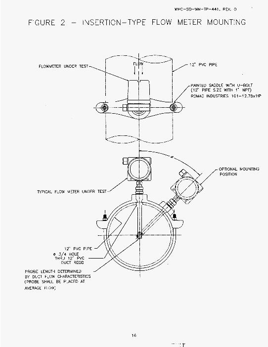
I n s t a l l t h e f l o w meter where i n d i c a t e d i n F i g u r e 1 u s i n g t h e sadd le c lamp p r o v i d e d as shown i n F i g u r e 2 .
Connect power t o t h e f l o w meter and connect i t s 4-20 mA o u t p u t t o t h e d a t a a c q u i s i t i o n system.
Program t h e f l o w meter p e r t h e m a n u f a c t u r e r ' s i n s t r u c t i o n s t o measure f l o w i n t h e 0-400 SCFM range.
F i l l o u t t h e t o p o f t h e Flow Meter Tes t Data Sheets ( A and B ) .
S t a r t t h e b lower and s e t t h e a i r f l o w as shown i n t h e Nominal A i r Flow Column on t h e Tes t Data Sheet. A l l o w t h e a i r f l o w t o s t a b i l i z e . Record t h e a i r s t r e a m tempera ture , t h e r e f e r e n c e d i f f e r e n t i a1 p ressu re , t h e r e f e r e n c e s t a t i c a i r p ressure , t h e o u t p u t o f t h e f l o w meter be ing t e s t e d and t h e t e s t f l o w meter s t a t i c p ressu re . Repeat these s teps u n t i l t h e Tes t Data Sheet i s f i l l e d o u t .
F i l l o u t t h e t o p o f a Flow Meter Step Response Tes t Data Sheet.
Set t h e nominal a i r f l o w th rough t h e system t o 50 SCFM. g a t e va l ves near t h e b lower t o a d j u s t t h e a i r f l o w th rough t h e bypass p o r t such t h a t when t h e bypass i s capped o f f t h e f l o w th rough t h e system inc reases t o 75 SCFM (50% i n c r e a s e ) .
A f t e r t h e a i r f l o w has s t a b i l i z e d a t 50 SCFM, s t a r t t h e d a t a a c q u i s i t i o n system t o r e c o r d d a t a eve ry second. Wai t t e n seconds and then cap o f f t h e bypass p o r t . cap f rom t h e bypass p o r t . Wai t t h i r t y seconds. S top t h e d a t a a c q u i s i t i o n system.
I n s t a l l t h e cap on t h e bypass p o r t and s e t t h e nominal a i r f l o w th rough t h e system a t 50 SCFM. Remove t h e cap and a d j u s t t h e bypass v a l v e t o a d j u s t t h e a i r f l o w th rough t h e system measures 25 SCFM (50% dec rease) .
Use t h e two
Wait t h i r t y seconds. Remove t h e
R e i n s t a l l t h e bypass cap and a l l o w t h e a i r f l o w t o s t a b i l i z e a t 50 SCFM. second. Wai t t e n seconds and then remove t h e cap f rom t h e bypass p o r t . Wai t t h i r t y seconds. Wai t t h i r t y seconds. Stop t h e d a t a a c q u i s i t i o n system.
Set t h e nominal a i r f l o w th rough t h e system t o 120 SCFM. Use t h e two g a t e va l ves near t h e b lower t o a d j u s t t h e a i r f l o w th rough t h e bypass p o r t such t h a t when t h e bypass i s capped o f f t h e f l o w th rough t h e system inc reases t o 180 SCFM (50% inc rease ) .
A f t e r t h e a i r f l o w has s t a b i l i z e d a t 120 SCFM, s t a r t t h e d a t a a c q u i s i t i o n system t o r e c o r d d a t a eve ry second. and then cap o f f t h e bypass p o r t . cap f rom t h e bypass p o r t . Wai t t h i r t y seconds. a c q u i s i t i o n system.
S t a r t t h e d a t a a c q u i s i t i o n system t o r e c o r d d a t a eve ry
R e i n s t a l l t h e cap on t h e bypass p o r t .
Wai t t e n seconds
Stop t h e d a t a Wai t t h i r t y seconds. Remove t h e
5

WHC-SD-WM-TP-441 REV 0
Install the cap on the bypass port amd set the nominal airflow through the system at 120 SCFM. Remove the cap and adjust the bypass valve to adjust the airflow through the system measures 60 SCFM (50% decrease).
Reinstall the bypass cap and allow the airflow to stabilize at 120 SCFM. second. thirty seconds. seconds.
Fill out the top of a Flow Meter Stability Test Data Sheet.
Start the air supply system and set the air,flow to 160 ft/min. Allow the airflow to stabilize. Start the data acquisition system to automatically log data for the next 24 hours. airstream temperature, the reference differential pressure, the reference static air pressure, the cutput of the flow meter being tested, the test flow meter static pressure and the system relative humidity.
After the 24 hours has elapsed, stop the air supply system, evaluate the test data, and determine if any additional testing is required. If not, proceed with the next flow weter.
Start the data acquisition system to record data every Wait ten seconds and then remove the bypass port. Wait
Reinstall the cap on the bypass port. Wait thirty Stop the data acquisition system.
Record the
6 . 3 . 2 Intek Flow Meter Testing
Install the flow meter where indicated in Figure 1 using the saddle clamp provided as shown in Figure 2 .
Connect power to the flow meter and connect its 4-20 mA output to the data acquisition system.
Program the flow meter per the manufacturer’s instructions to measure flow in the 0-400 SCFM range.
Fill out the top of the Flow Meter lest Data Sheets (A and B ) .
Start the blower and set the air flow as shown in the Nominal Air Flow Column on the Test Data Sheet. Allow the airflow to stabilize. Record the airstream temperature, the reference differential pressure, the reference static air pressure, the output of the flow meter being tested and the test flobl meter static pressure. Repeat these steps until the Test Data Sheet is filled out.
Fill out the top of a Flow Meter Step Response Test Data Sheet.
Set the nominal airflow through the system to 50 SCFM. gate valves near the blower to adjust the airflow through the bypass port such that when the bypass i s capped off the flow through the system increases to 75 SCFM (50% increase).
After the airflow has stabilized at 50 SCFM, start the data acquisition system to record data every second. and then cap off the bypass port.
Use the two
Wait ten seconds klait thirty seconds. Remove the
6
WHC-SD-WM-TP-441 REV 0
6.3.
cap f rom t h e bypass p o r t . Stop t h e da ta a c q u i s i t i o n system.
I n s t a l l t h e cap on t h e bypass p o r t aind s e t t h e nominal a i r f l o w th rough t h e system a t 50 SCFM. Remove t h e cap and a d j u s t t h e bypass v a l v e t o a d j u s t t h e a i r f l o w th rough the system measures 25 SCFM (50% decrease) .
R e i n s t a l l t h e bypass cap and a l l o w t h e a i r f l o w t o s t a b i l i z e a t 50 SCFM. second. Wai t t e n seconds and t h e n remove t h e cap f rom t h e bypass p o r t . Wai t t h i r t y seconds. R e i n s t a l l t h e cap on t h e bypass p o r t . Wai t t h i r t y seconds.
Wai t t h i r t y seconds.
S t a r t t h e d a t a a c q u i s i t i o n system t o r e c o r d d a t a eve ry
Stop t h e d a t a a c q u i s i t i o n system.
Set t h e nominal a i r f l o w th rough t h e system t o 120 SCFM. Use t h e two g a t e va l ves near t h e b lower t o a d j u s t t h e a i r f l o w th rough t h e bypass p o r t such t h a t when t h e bypass i s capped o f f t h e f l o w th rough t h e system inc reases t o 180 SCFM (50% i n c r e a s e ) .
A f t e r t h e a i r f l o w has s t a b i l i z e d a t 120 SCFM, s t a r t t h e d a t a a c q u i s i t i o n system t o r e c o r d d a t a eve ry second. Wai t t e n seconds and then cap o f f t h e bypass p o r t . cap f rom t h e bypass p o r t . a c q u i s i t i o n system.
I n s t a l l t h e cap on t h e bypass p o r t and s e t t h e nomina l a i r f l o w th rough t h e system a t 120 SCFM. Remove t h e cap and a d j u s t t h e bypass v a l v e t o a d j u s t t h e a i r f l o w th rough t h e system measures 60 SCFM (50% decrease) .
Wai t t h i r t y seconds. Remove t h e Wait t h i r t y seconds. S top t h e d a t a
R e i n s t a l l t h e bypass cap and a l l o w t h e a i r f l o w t o s t a b i l i z e a t 120 SCFM. S t a r t t h e d a t a a c q u i s i t i o n system t o r e c o r d d a t a eve ry second. Wait t e n seconds and then remove t h e bypass p o r t . t h i r t y seconds. R e i n s t a l l t h e cap on t h e bypass p o r t . Wai t t h i r t y seconds.
F i l l o u t t h e t o p o f a F low Meter S t a b i l i t y Tes t Data Sheet.
S t a r t t h e a i r supp ly system and s e t t h e a i r f l o w t o 160 f t /m in . A l l o w t h e a i r f l o w t o s t a b i l i z e . S t a r t t h e d a t a a c q u i s i t i o n system t o a u t o m a t i c a l l y l o g d a t a f o r t h e n e x t 24 hours . a i r s t r e a m tempera ture , t h e r e f e r e n c e d i f f e r e n t i a l p ressu re , t h e r e f e r e n c e s t a t i c a i r p ressu re , t h e o u t p u t o f t h e f l o w meter b e i n g t e s t e d , t he t e s t f l o w meter s t a t i c p ressu re and t h e system r e l a t i v e h u m i d i t y .
A f t e r t h e 24 hours has e lapsed, s t o p t h e a i r supp ly system, e v a l u a t e t h e t e s t da ta , and de termine i f any a d d i t i o n a l t e s t i n g i s r e q u i r e d . I f n o t , p roceed w i t h t h e n e x t f l o w meter .
Wai t
S top t h e d a t a a c q u i s i t i o n system.
Record t h e
3 A i r M o n i t o r Corpo ra t i on Flow Meter T e s t i n g
I n s t a l l t h e f l o w meter where i n d i c a t e d i n F i g u r e 1. D r i l l a d d i t i o n a l mount ing h o l e s as r e q u i r e d .
7

WHC-SD-WM-TP-441 REV 0
Connect power t o t h e f l o w meter and connect i t s 4-20 mA o u t p u t t o t h e d a t a a c q u i s i t i o n system.
Program t h e f l o w meter p e r t h e manu fac tu re r ' s i n s t r u c t i o n s t o measure f l o w i n t h e 0-400 SCFM range.
F i l l o u t t h e t o p o f t h e Flow Meter Tes t Data Sheets (A and B) .
S t a r t t h e b lower and s e t t h e a i r f l o w as shown i n t h e Nominal A i r F low Column on t h e Tes t Data Sheet. A l l o w t h e a i r f l o w t o s t a b i l i z e . Record t h e a i r s t r e a m tempera ture , t h e r e f e r e n c e d i f f e r e n t i a l p ressu re , t h e r e f e r e n c e s t a t i c a i r p ressure , t h e o u t p u t o f t h e f l o w meter be ing t e s t e d and t h e t e s t f l o w meter s t a t i c p ressu re . Repeat these s teps u n t i l t h e T e s t Data Sheet i s f i l l e d o u t .
F i l l o u t t h e t o p o f a Flow Meter S tep Response Tes t Data Sheet.
Set t h e nominal a i r f l o w th rough t h e system t o 50 SCFM. g a t e va l ves near t h e b lower t o a d j u s t t h e a i r f l o w th rough t h e bypass p o r t such t h a t when t h e bypass i s capped o f f t h e f l o w th rough t h e system inc reases t o 75 SCFM (50% inc rease ) .
A f t e r t h e a i r f l o w has s t a b i l i z e d a t 50 SCFM, s t a r t t h e d a t a a c q u i s i t i o n system t o r e c o r d d a t a eve ry second. and then cap o f f t h e bypass p o r t . cap f rom t h e bypass p o r t . Wai t t h i r t y seconds. a c q u i s i t i o n system.
I n s t a l l t h e cap on t h e bypass p o r t and s e t t h e nominal a i r f l o w th rough t h e system a t 50 SCFM. Remove t h e cap and a d j u s t t h e bypass v a l v e t o a d j u s t t h e a i r f l o w th rough t h e system measures 25 SCFM (50% dec rease) .
R e i n s t a l l t h e bypass cap and a l l o w t h e a i r f l o w t o s t a b i l i z e a t 50 SCFM. second. Wai t t e n seconds and then remove t h e cap f rom t h e bypass p o r t . Wai t t h i r t y seconds. S top t h e d a t a a c q u i s i t i o n system.
Set t h e nominal a i r f l o w th rough t h e system t o 120 SCFM. Use t h e two g a t e va l ves near t h e b lower t o a d j u s t t h e a i r f l o w th rough t h e bypass p o r t such t h a t when t h e bypass i s capped o f f t h e f l o w th rough t h e system inc reases t o 180 SCFM (50% i n c r e a s e ) .
A f t e r t h e a i r f l o w has s t a b i l i z e d a t 120 SCFM, s t a r t t h e d a t a a c q u i s i t i o n system t o r e c o r d d a t a eve ry second. Wai t t e n seconds and then cap o f f t h e bypass p o r t . cap f rom t h e bypass p o r t . Wai t t h i r t y seconds. S top t h e d a t a a c q u i s i t i o n system.
I n s t a l l t h e cap on t h e bypass p o r t and s e t t h e nomina l a i r f l o w th rough t h e system a t 120 SCFM. Remove t h e cap and a d j u s t t h e bypass v a l v e t o a d j u s t t h e a i r f l o w th rough t h e system measures 60 SCFM (50% decrease) .
Use t h e two
Wai t t e n seconds
Stop t h e d a t a Wai t t h i r t y seconds. Remove t h e
S t a r t t h e d a t a a c q u i s i t i o n system t o r e c o r d d a t a eve ry
Wai t t h i r t y seconds. R e i n s t a l l t h e cap on t h e bypass p o r t .
Wai t t h i r t y seconds. Remove t h e
a

WHC-SD-WM-TP-441 REV 0
Reinstall the bypass cap and allow the airflow to stabilize at 120 SCFM. second. thirty seconds. seconds.
Fill out the top of a Flow Meter Stability Test Data Sheet.
Start the air supply system and set the air flow t o 160 ft/min. Allow the airflow to stabilize. to automatically log data for the next 24 hours. airstream temperature, the reference differential pressure, the reference static air pressure, the output of the flow meter being tested, the test flow meter static pressure and the system relative humi di ty . After the 24 hours has elapsed, stop the air supply system, evaluate the test data, and determine if any additional testing is required. If not, proceed with the next flow meter.
Start the data acquisition sy!jtem to record data every Wait ten seconds and then remove the bypass port. Wait
Wait thirty Reinstall the cap on the bypass port. Stop the data acquisition :jystem.
Start the data acquisition system Record the
6.3.4 Panametrics Flow Meter Testing
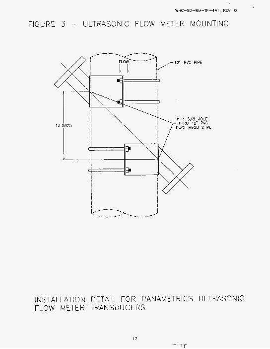
Install the flow meter where indicated in Figure 1. Mount the two saddles horizontally across the duct, centered on the 6'-11" distance. See Figure 3 .
Connect power to the flow meter and connect its 4-20 mA output to the data acquisition system.
Program the flow meter per the manufacturer's instructions to measure flow in the 0-400 SCFM range.
Fill out the top of the Flow Meter Test Data Sheets (A and 8 ) .
Start the blower and set the air flow as shown in the Nominal Air Flow Column on the Test Data Sheet. Allow the airflow to stabilize. Record the airstream temperature, the reference differential pressure, the reference static air pressure, the output of the flow meter being tested and the test flow meter static pressure. Repeat these steps until the Test Data Sheet is filled out.
Fill out the top of a Flow Meter Step Response Test Data Sheet.
Set the nominal airflow through the system to 50 SCFM. Use the two gate valves near the blower to adjust the airflow through the bypass port such that when the bypass is capped off the flow through the system increases to 75 SCFM (50% increase).
After the airflow has stabilized at 50 SCFM, start the data acquisition system to record data every second. and then cap off the bypass port. cap from the bypass port. Wait thirty seconds. acquisition system.
Wait ten seconds
Stop the data Wait thirty seconds. Remove the
9
( 7 ir ...,.. ,
WHC-SD-WM-TP-441 RlfV 0
I n s t a l l t h e cap on t h e bypass p o r t and s e t t h e nominal a i r f l o w th rough t h e system a t 50 SCFM. Remove t h e cap and a d j u s t t h e bypass v a l v e t o a d j u s t t h e a i r f l o w th rough t h e system measures 25 SCFM (50% decrease) .
R e i n s t a l l t h e bypass cap and a l l o w t h e a i r f l o w t o s t a b i l i z e a t 50 SCFM. second. Wait t e n seconds and then remove t h e cap f rom t h e bypass p o r t . Wait t h i r t y seconds. R e i n s t a l l t h e cap on t h e bypass p o r t . Wait t h i r t y seconds. Stop t h e d a t a a c q u i s i t i o n system.
Set t h e nominal a i r f l o w th rough t h e system t o 120 SCFM. Use t h e two g a t e v a l v e s near t h e blower t o a d j u s t t h e a i r f l o w t h r o u g h t h e bypass p o r t such t h a t when t h e bypass i s capped o f f , t h e f l o w t h r o u g h t h e system increases t o 180 SCFM (50% i n c r e a s e ) .
A f t e r t h e a i r f l o w has s t a b i l i z e d a t 120 SCFM, s t a r t t h e d a t a a c q u i s i t i o n system t o r e c o r d da ta e v w y second. and then cap o f f t h e bypass p o r t . Wait t h i r t y seconds. cap f rom t h e bypass p o r t . Wait t h i r t y seconds. Stop t h e d a t a a c q u i s i t i o n system.
I n s t a l l t h e cap on t h e bypass p o r t and s e t t h e nominal a i r f l o w t h r o u g h t h e system a t 120 SCFM. Remove t h e cap and a d j u s t t h e bypass v a l v e t o a d j u s t t h e a i r f l o w th rough t h e system measures 60 SCFM (50% decrease) .
R e i n s t a l l t h e bypass cap and a l l o w t h e a i r f l o w t o s t a b i l i z e a t 120 SCFM. S t a r t t h e d a t a a c q u i s i t i o n system t o r e c o r d d a t a every second. Wait t e n seconds and then remove t h e bypass p o r t . t h i r t y seconds. R e i n s t a l l t h e cap on t h e bypass p o r t . Wait t h i r t y seconds.
F i l l o u t t h e t o p o f a Flow Meter S t a b i l i t y Tes t Data Sheet.
S t a r t t h e d a t a a c q u i s i t i o n system t o r e c o r d d a t a every
Wait t e n seconds Remove t h e
Wait
Stop t h e d a t a a c q u i s i t i o n system.
S t a r t t h e a i r supp ly system and s e t t h e a i r f l o w t o 160 f t / m i n . A l l o w t h e a i r f l o w t o s t a b i l i z e . t o a u t o m a t i c a l l y l o g d a t a f o r t h e n e x t 24 hours. Record t h e a i r s t r e a m tempera ture , t h e r e f e r e n c e d i f f e r e n t i a l p ressure , t h e r e f e r e n c e s t a t i c a i r p ressure , t h e o u t p u t o f t h e f l o w meter be ing t e s t e d , t h e t e s t f l o w meter s t a t i c p ressure and t h e system r e l a t i v e h u m i d i t y . A f t e r t h e 24 hours has elapsed, s t o p t h e a i r supp ly system, e v a l u a t e t h e t e s t da ta , and de termine i f any a d d i t i o n a l t e s t i n g i s r e q u i r e d . I f n o t , proceed w i t h t h e h i g h h u m i d i t y t e s t i n g .
S t a r t t h e d a t a a c q u i s i t i o n system
6.5 H igh Humid i ty T e s t i n g
For t h i s p o r t i o n o f t h e t e s t t h e a i r s t r e a m h u m i d i t y w i l l be m a i n t a i n e d a t 50-90 % r . h . .
10

WHC-SD-WM-TP-441 R.EV 0
6.5.1 Sierra Flow Meter Testing
Install the flow meter where indicated in Figure 1 using the saddle clamp provided as shown in Figure 2.
Connect power to the flow meter and connect its 4-20 mA output to the data acquisition system.
Program the flow meter per the manufacturer's instructions to measure flow in the 0-400 SCFM range.
Fill out the top o f a Flow Meter Test Data Sheet.
Start the air supply system and set the air flow to 160 ft/min. Allow the airflow to stabilize. allow the system to reach 50 to 90 % r.h.. Start the data acquisition system to automatically l og data for the next 48 hours. Record the airstream temperature, the reference differential pressure, the reference static air pressure, the output of the flow meter being tested, the test flow meter static pressure and the system relative humidity.
Start the humidification system and
6.5.2 Intek Flow Meter Testing
Install the flow meter where indicated in Figure 1 using the saddle clamp provided as shown in Figure 2.
I Connect power to the flow meter and connect its 4-20 mA output to the data acquisition system.
Program the flow meter per the manufacturer's instructions to measure flow in the 0-400 SCFM range.
Fill out the top of a Flow Meter Test Data Sheet.
Start the air supply system and set the air flow to 160 ft/min. Allow the airflow to stabilize. Start the humidification system and allow the system to reach 50 to 90 % r.h.. acquisition system to automatically log data for the next 48 hours. Record the airstream temperature, the reference differential pressure, the reference static air pressure, the output of the flow meter being tested, the test flow meter static pressure and the system relative humidity.
1
Start the data
6.5.3 Air Monitor Corporation Flow Meter Testing
Install the flow meter where indicated in Figure 1. Drill additional mounting holes as required.
Connect power to the flow meter and connect its 4-20 mA output to the data acquisition system.
11

WHC-SD-WM-TP-441 FlEV 0
Program the flow meter per the manufacturer's instructions to measure flow in the 0-400 SCFM range.
Fill out the top of a Flow Meter Test Data Sheet.
Start the air supply system and set the air flow to 160 ft/min. Allow the airflow to stabilize. Start the humidification system and allow the system to reach 50 to 90 % r.h.. Start the data acquisition system to automatically log data for the next 48 hours. Record the airstream temperature, the reference differential pressure, the reference static air pressure, the output of the flow
system re1 ative humidity . ,meter being tested, the test flow meter static pressure and the
6.5.4 Panametrics Flow Meter Testing
Install the flow meter where indicated in Figure 1. Mount the two saddles horizontally across the duct, centered on the 6'-11" distance. See Figure 3 .
1 Connect power to the flow meter and connect its 4-20 mA output to the data acquisition system.
Program the flow meter per the manufacturer's instructions to measure flow in the 0-400 SCFM range.
Fill out the top of a Flow Meter Test Data Sheet.
Start the air supply system and set the air flow to 160 ft/min. Allow the airflow to stabilize. Start the humidification system and allow the system to reach 50 to 90 % r.h.. acquisition system to automatically log data for the next 48 hours. Record the airstream temperature, the reference differential pressure, the reference static air pressure, the output of the flow meter being tested, the test flow meter static pressure and the system re1 at ive humidity.
Start the data
7.0 SAFETY
No unique or unusual industrial, radiological, chemical, fire, release of energy, or criticality safety hazards are involved with performing or supporting these tests. Only the test director, cognizant test engineers and/or their approved personnel shall operate the test equipment. A Hanford Job Hazard Analysis, a 306E Specific Job Hazard Analysis and an Environmental Compliance Screening Checklist for the 306E Complex will be prepared prior to the start of testing. test personnel as documented on the Job Hazard Analysis Signoff Sheet.
A prejob safety briefing will be conducted with all
The air blower has a sound pressure level of 85-95 dB(A) at three feet. The intake and bypass ports will be diverted downhlard to reduce the noise level but hearing protection may still be required around the test mockup. Industrial Hygiene will make a final determina,tion after the system is operable.
12

WHC-SD-WM-TP-441 REV 0
Compressed air ( - 3 0 psi) and pressurized water (-20 psi) will be used during the humidity portion of this test. Normal industrial safety precautions should be used with the air and water.
The 306E Facility Manager or his designee must be notified prior to commencement of testing.
8.0 QUALITY ASSURANCE
A Quality Assurance representative shall review this document as well as the test report when it is prepared.
No witnesses or hold points are required durinmg testing but interested observers will be allowed.
9.0 ORGANIZATION AND FUNCTION RESPONSIBILITIES
9.1 Characterization Equipment Development (75240)
A Characterization Equipment Development engineer shall review this document as well as the test report when it is prepared.
9.2 Equipment Development (8A200)
Equipment Development will provide a Test Director for this test. director will have overall responsibility for the performance of this test. Equipment Development will also provide personnel for test preparation, test maintenance, equipment disassembly and general assistance during testing.
9.3 Analytical Services (5A620)
Analytical Services will prepare this test p1a.n and the test report for this testing. Analytical Services will also provide the Test Performer for this test.
The
10.0 SCHEDULE:
Testing will start as soon as this Test Plan is approved and released by Document Control. Testing will .last for approximately five weeks, after which the test data will be evaluated and the test report prepared.
11.0 REPORTS
The test data and a recommendation for a flow meter to be installed in the field will be presented in WHC-SD-WM-TRP-254, Jest Report o f Evaluation o f Primary Exhaust Ventilation f l o w Meters for Double Shell Hydrogen Watch List Tanks, following the completion of the testing.
13

WHC-SD-WM-TP-441 REV 0
12.0 REFERENCES
12.1 West inghouse Hanford Company, WHC-SD-WM-DRD-003, Rev. 0 , Des ign Requirements Document - Pr imary V e n t i l a t i o n Flow M o n i t o r i n g f o r DSTs on t h e Hydrogen Watch L i s t , 1 0 / 9 / 9 5 , R ich la r id , Washington.
Des ign and I n s t a l l a t i o n o f P r imary Exhaust V e n t i l a t i o n Flow M o n i t o r i n g i n Double S h e l l Hydrogen Watch L i s t Tanks, 9 / 7 / 9 5 , R ich land , Washington.
12.3 West inghouse Hanford Company, WHC-SD-WM-CDR-026, Rev. 0 , Eng ineer ing S tudy and Conceptual Des ign Repor t f o r P r imary V e n t i l a t i o n Duct Flow M o n i t o r i n g , 1 0 / 3 1 / 9 5 , R ich land , Washington.
12.4 West inghouse Hanford Company, WHC-SD-WM-E:TP-178, 'Rev. 0 , Task P l a n for t h e S e l e c t i o n and E v a l u a t i o n o f Flow M o n i t o r i n g I n s t r u m e n t a t i o n t o be Used on t h e P r imary Exhaust V e n t i l a t i o n I n Double S h e l l Hydrogen Watch L i s t Tanks, 1 2 / 4 / 9 5 , R ich land , Washington.
12.2 West inghouse Hanford Company, WHC-SD-WM-EITP-156, Rev. 0 , Task P lan f o r
14
WHC-SD-WM-TP-441, REV. 0
FIGURE 2 - INSERTION-TYPE FLOW METER MOUNTING
FLOWMETER UNDER TESl
TYPICAL FLOW METER UNDER TEST
DUCT REOD
i PROBE LENGTH DnERMINED BY DUCT FLOW CHARACTERISTICS (PROBE SHALL BE PLACED AT
AVERAGE FLOW)
OPTIONAL MOUNTING POSITION
16
' T ",.. ,
WHC-SD-WM-TP-441, REV. 0
FIGURE 3 - ULTRASONIC FLOW METER MOUNTING
INSTALLATION DETAIL FOR PANAMETRICS ULTRASONIC FLOW METER TRANSDUCERS
17

WHC-SD-WM-TP-441 RlEV 0
TEST EQUIPMENT DATA .SHEET
Laminar Flow Element, Meriam Instrument Mcidel 50MC2-4, nominal 400 scfm air flow at 8" wc and 70 degrees F and 29.92" Hg abs.
Seri a1 Number Factory Calibration:
Ashcroft ATE-100 Handheld Pressure Calibrator, Port 1: 0-25 in.H,O input range, Port 2: 0-30 psia input range.
Serial Number Calibration:
Absolute Pressure Transmitter, Rosemount Model 3051C, 0-30 psia input range, 4-20 mA output.
Seri a1 Number Calibration:
Humidity Probe
Model Number Seri a1 Number. Calibration:
RTD, Platinum, 100 Ohm, Gordon Model RFHLDTKlOOCA200
Temperature Indicator/Transmitter, Newport Electronics Model INFU-0010-DC1
Seri a1 Number Calibration:
Computer, I B M PC/XT/AT, Model Number-
Serial Number Property Number
Data acquisition software
Model Number Version Seri a1 Number
Power Supply, 120V AC input, 24V DC output.
Model Number Serial Number
Test Performer Date
Test Director Date
18

WHC-SO-WM-TP-441 REV 0
FLOW METER TEST DATA SHEET - AMBIENT, PAGE A
F l o w Meter Manu fac tu re r
Model Number S e r i a1 Number
Ambient Temperature Ambient Humid i t y
Flow Meter mount ing l o c a t i o n , o r i e n t a t i o n
B u t t e r f l y Valve P o s i t i o n
Probe i n s e r t i o n dep th
Data F i l e Name
T e s t Per fo rmer Date
Tes t D i r e c t o r Date
19

WHC-SD-WM-TP-441 REV 0
FLOW METER TEST DATA SHEET - AMBIENT, PAGE B
Flow Mete r Manu fac tu re r
Model Number S e r i a1 Number
Ambient Temperature Ambient H u m i d i t y
F low Mete r mount ing l o c a t i o n , o r i e n t a t i o n
B u t t e r f l y Va lve P o s i t i o n
Probe i n s e r t i o n d e p t h
Data F i l e Name
COMMENTS :
Calculated Flow meter Air Flow 7 (SCFM)
T e s t Pe r fo rmer Date
Tes t D i r e c t o r Date
20

WHC-SD-WM-TP-441 R E V 0
FLOW METER TEST DATA SHEET - HIGH HUMIDITY
F l o w Me te r Manu fac tu re r
Model Number S e r i a1 Number
Ambient Temperature Ambient H u m i d i t y
F low Mete r mount ing l o c a t i o n , o r i e n t a t i o n
B u t t e r f l y Va lve P o s i t i o n
Probe i n s e r t i o n dep th
Data F i l e Name
Comments :
T e s t Pe r fo rmer Date
Tes t D i r e c t o r Date
21

WHC-SD-WM-TP-441 REV 0
FLOW HETER STABILITY TEST DATA SHEET
Flow Meter Manu fac tu re r
Model Number S e r i a1 Number
Ambient Temperature Ambient Humid i t y
f l o w Meter mount ing l o c a t i o n , o r i e n t a t i o n
B u t t e r f l y Va lve P o s i t i o n
Probe i n s e r t i o n dep th
Data F i l e Name
Comments :
Tes t Pe r fo rmer Date
Tes t D i r e c t o r Date
22
' T
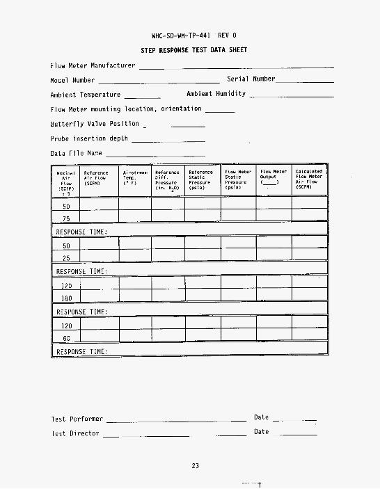
Nominal Reference Airstream Reference ~ i r Air Flou Tenp. D i f f . Flou ( S C F M ) ( " F ) Pressure
t 5 ( S C F M ) ( i n . HZO)
50
75
T e s t P e r f o r m e r Date
T e s t D i r e c t o r Date
Reference Flou Meter Flou Meter Calculated Sta t ic Output Flou Meter s t a t i c
Pressure (psia) ( p i a )
A i r Flou
23

WHC-SD-WM-TP-441 REV 0
Flow and V e l o c i t y Reference Tab le
( f o r 12-5/8" d iameter d u c t )

T o
D i s t r i b u t i o n
Name
From
W . E . W i l l i n g h a m J r . S . K . Fa rnwor th T. C . Schneider D. D . Ta te E . A . Smi th D. 8. Engelman J . W . Len tsch B . J . Hug J . R. T h i e l g e s D. G . Panther Cen t ra l F i l e s
I Text Only I ;;E;;: 1 E D ; y 1 MSIN I At tach . Only
H6-11 x H5-56 X L6-37 X L6-37 X 64-40 X L6-37 X S7-12 X L6-35 X L6-38 X L6-39 X A3-88 X