POWER WAVE S350 CE - arcweld.co.nz Proceess... · IM2034 05/2010 Rev. 0 POWER WAVE S350 CE...
18
IM2034 05/2010 Rev. 0 POWER WAVE S350 CE OPERATOR’S MANUAL ENGLISH THE LINCOLN ELECTRIC COMPANY 22801 St. Clair Ave., Cleveland Ohio 44117-1199 USA www.lincolnelectric.eu ARC WELDING SUPPLIES - 07 847 7870
Transcript of POWER WAVE S350 CE - arcweld.co.nz Proceess... · IM2034 05/2010 Rev. 0 POWER WAVE S350 CE...
IM2034 05/2010
Rev. 0
POWER WAVE S350 CE
OPERATOR’S MANUAL
ENGLISH
THE LINCOLN ELECTRIC COMPANY 22801 St. Clair Ave., Cleveland Ohio 44117-1199 USA
www.lincolnelectric.eu
ARC W
ELDIN
G SUPP
LIES
- 07
847
787
0
English English I
THE LINCOLN ELECTRIC COMPANY
EC DECLARATION OF CONFORMITY Manufacturer and technical documentation holder:
The Lincoln Electric Company
Address:
22801 St. Clair Ave. Cleveland Ohio 44117-1199 USA
EC Company:
Lincoln Electric Europe S.L.
Address:
c/o Balmes, 89 - 80 2a 08008 Barcelona SPAIN
Hereby declare that welding equipment:
Power Wave S350 CE, including options and accessories STT Module
Sales code:
K2823, code may also contain prefixes and suffixes K2921, code may also contain prefixes and suffixes
Is in conformity with Council Directives and amendments:
EMC Directive 2004/108/EC
Low Voltage Directive 2006/95/EC
Standards: EN 60974-1, Arc Welding Equipment – Part 1: Welding Power Sources, 2005 EN 60974-10 Arc Welding Equipment – Part 10: Electromagnetic compatibility (EMC) requirements, 2003
Frank Stupczy, Manufacturer Dario Gatti, European Community Representative
Compliance Engineering Manager European Engineering Director Machines 18 March 2010 19 March 2010 MCD235
ARC W
ELDIN
G SUPP
LIES
- 07
847
787
0
English English II
12/05
THANKS! For having choosen the QUALITY of the Lincoln Electric products. • Please Examine Package and Equipment for Damage. Claims for material damaged in shipment must be notified
immediately to the dealer. • For future reference record in the table below your equipment identification information. Model Name, Code &
Serial Number can be found on the machine rating plate.
Model Name:
………………...…………………………….………………………………………………………………………………………….. Code & Serial number:
………………….……………………………………………….. …………………………………………………….……………..
Date & Where Purchased:
…………………………………………………………………... ……………………….…………………………………………..
ENGLISH INDEX Safety .............................................................................................................................................................................. 1 Installation and Operator Instructions .............................................................................................................................. 2 Electromagnetic Compatibility (EMC) .............................................................................................................................. 7 Technical Specifications .................................................................................................................................................. 8 WEEE .............................................................................................................................................................................. 8 Spare Parts ...................................................................................................................................................................... 8 Electrical Schematic ........................................................................................................................................................ 9 Accessories ..................................................................................................................................................................... 9
ARC W
ELDIN
G SUPP
LIES
- 07
847
787
0

English English 1
Safety 11/04
WARNING This equipment must be used by qualified personnel. Be sure that all installation, operation, maintenance and repair procedures are performed only by qualified person. Read and understand this manual before operating this equipment. Failure to follow the instructions in this manual could cause serious personal injury, loss of life, or damage to this equipment. Read and understand the following explanations of the warning symbols. Lincoln Electric is not responsible for damages caused by improper installation, improper care or abnormal operation.
WARNING: This symbol indicates that instructions must be followed to avoid serious personal injury, loss of life, or damage to this equipment. Protect yourself and others from possible serious injury or death.
READ AND UNDERSTAND INSTRUCTIONS: Read and understand this manual before operating this equipment. Arc welding can be hazardous. Failure to follow the instructions in this manual could cause serious personal injury, loss of life, or damage to this equipment.
ELECTRIC SHOCK CAN KILL: Welding equipment generates high voltages. Do not touch the electrode, work clamp, or connected work pieces when this equipment is on. Insulate yourself from the electrode, work clamp, and connected work pieces.
ELECTRICALLY POWERED EQUIPMENT: Turn off input power using the disconnect switch at the fuse box before working on this equipment. Ground this equipment in accordance with local electrical regulations.
ELECTRICALLY POWERED EQUIPMENT: Regularly inspect the input, electrode, and work clamp cables. If any insulation damage exists replace the cable immediately. Do not place the electrode holder directly on the welding table or any other surface in contact with the work clamp to avoid the risk of accidental arc ignition.
ELECTRIC AND MAGNETIC FIELDS MAY BE DANGEROUS: Electric current flowing through any conductor creates electric and magnetic fields (EMF). EMF fields may interfere with some pacemakers, and welders having a pacemaker shall consult their physician before operating this equipment.
CE COMPLIANCE: This equipment complies with the European Community Directives.
FUMES AND GASES CAN BE DANGEROUS: Welding may produce fumes and gases hazardous to health. Avoid breathing these fumes and gases. To avoid these dangers the operator must use enough ventilation or exhaust to keep fumes and gases away from the breathing zone.
ARC RAYS CAN BURN: Use a shield with the proper filter and cover plates to protect your eyes from sparks and the rays of the arc when welding or observing. Use suitable clothing made from durable flame-resistant material to protect you skin and that of your helpers. Protect other nearby personnel with suitable, non-flammable screening and warn them not to watch the arc nor expose themselves to the arc.
WELDING SPARKS CAN CAUSE FIRE OR EXPLOSION: Remove fire hazards from the welding area and have a fire extinguisher readily available. Welding sparks and hot materials from the welding process can easily go through small cracks and openings to adjacent areas. Do not weld on any tanks, drums, containers, or material until the proper steps have been taken to insure that no flammable or toxic vapors will be present. Never operate this equipment when flammable gases, vapors or liquid combustibles are present.
WELDED MATERIALS CAN BURN: Welding generates a large amount of heat. Hot surfaces and materials in work area can cause serious burns. Use gloves and pliers when touching or moving materials in the work area.
SAFETY MARK: This equipment is suitable for supplying power for welding operations carried out in an environment with increased hazard of electric shock.
ARC W
ELDIN
G SUPP
LIES
- 07
847
787
0

English English 2
CYLINDER MAY EXPLODE IF DAMAGED: Use only compressed gas cylinders containing the correct shielding gas for the process used and properly operating regulators designed for the gas and pressure used. Always keep cylinders in an upright position securely chained to a fixed support. Do not move or transport gas cylinders with the protection cap removed. Do not allow the electrode, electrode holder, work clamp or any other electrically live part to touch a gas cylinder. Gas cylinders must be located away from areas where they may be subjected to physical damage or the welding process including sparks and heat sources.
NOISE APPEARES DURING WELDING CAN BE HARMFUL: Welding arc can cause noise with high level of 85dB for 8-hour week day. Welders operating welding machines are obligated to wear the proper ear protectors /appendix No. 2 for the Decree of the Secretary of Labor and Social Policy from 17.06 1998 – Dz.U. No. 79 pos. 513/. According to the Decree the Secretary of Health and Social Welfare from 09.07.1996 /Dz.U. No. 68 pos. 194/, employers are obligated to carry examinations and measurements of health harmful factors. MOVING PARTS ARE DANGEROUS: There are moving mechanical parts in this machine, which can cause serious injury. Keep your hands, body and clothing away from those parts during machine starting, operating and servicing.
Installation and Operator Instructions Read this entire section before installation or operation of the machine. Location and Environment THE POWER WAVE® S350CE will operate in harsh environments. Even so, it is important that simple preventative measures are followed in order to assure long life and reliable operation. • The machine must be located where there is free
circulation of clean air such that air movement in the back, out the sides and bottom will not be restricted.
• Dirt and dust that can be drawn into the machine should be kept to a minimum. The use of air filters on the air intake is not recommended because normal air flow may be restricted. Failure to observe these precautions can result in excessive operating temperatures and nuisance shutdown.
• Keep machine dry. Shelter from rain and snow. Do not place on wet ground or in puddles.
• Do not mount the POWER WAVE® S350 CE over combustible surfaces. Where there is a combustible surface directly under stationary or fixed electrical equipment, that surface shall be covered with a steel plate at least 1.6mm thick, which shall extend not less than 150mm beyond the equipment on all sides.
Lifting
WARNING FALLING EQUIPMENT can cause injury. • Lift only with equipment of adequate lifting capacity. • Be sure machine is stable when lifting. • Do not operate machine while suspended when
lifting. Both handles should be used when lifting POWER WAVE® S350 CE. When using a crane or overhead device a lifting strap should be connected to both handles. Do not attempt to lift the POWER WAVE®
S350 CE with accessories attached to it.
Stacking The POWER WAVE® S350 CE cannot be stacked. Tilting Place the machine directly on a secure, level surface or on a recommended undercarriage. The machine may topple over if this procedure is not followed. Duty Cycle and Overheating The POWER WAVE® S350 CE is rated at 300 amps at 29 volts with a 100% duty cycle. It is further rated to provide 350 amps at 31,5 volts with a 40% duty cycle. The duty cycle is based on a ten-minute period. A 40% duty cycle represents 6 minutes of welding and 4 minutes of idling in a 10-minute period. Example: 40% Duty Cycle:
Welding for 4 minutes. Break for 6 minutes.
Minutes or decrease
Duty Cycle
Preparation for Work Input and Ground Connections
WARNING Only a qualified electrician should connect the input leads to the POWER WAVE® S350 CE. Connections should be made in accordance with all local and national electrical codes and the connection diagram located on the inside of the reconnect access door of the machine. Failure to do so may result in bodily injury or death.
ARC W
ELDIN
G SUPP
LIES
- 07
847
787
0
English English 3
Machine Grounding The frame of the welder must be grounded. A ground terminal marked with a ground symbol is located next to the input power connection block. See your local and national electrical codes for proper grounding methods. High Frequency Protection The EMC classification of the POWER WAVE® S350 CE is Industrial, Scientific and Medical (ISM) group 2, class A. The POWER WAVE® S350 CE is for industrial use only (see Electromagnetic Compatibility EMC Safety Section). Locate the POWER WAVE® S350 CE away from radio controlled machinery. The normal operation of the POWER WAVE® S350 CE may adversely affect the operation of RF controlled equipment, which may result in bodily injury or damage to the equipment. Input Connection • 4.6m power cord is provided and wired into the
machine. • Single Phase Input - Not supported. • Three Phase Input - Connect green/yellow lead to
ground per National Electric Code. Connect grey, brown and black leads to power.
• The POWER WAVE® S350 CE automatically adjusts to work with different input voltages. No reconnect switches settings are required.
WARNING
The POWER WAVE® S350 CE ON/OFF switch is not intended as a service disconnect for this equipment. Power Cord Replacement If the input power cord is damaged or needs to be replaced an input power connection block is located in the access panel under the wire spool.
WARNING ALWAYS CONNECT THE POWER WAVE GROUNDING LUG (LOCATED INSIDE THE ACCESS PANEL) TO A PROPER SAFETY (EARTH) GROUND. Operation – General Power-up Sequence When the POWER WAVE® S350 CE is powered it can take as long as 30 seconds for the machine to be ready to weld. During this time period the user interface will not be active. Product Description The POWER WAVE® S350 CE is a high performance multi-process machine with GMAW, FCAW, SMAW, DC TIG, and pulse capability. It will offer a premier welding performance solution for specific areas such as aluminum, stainless, nickel where size and weight are an issue.
The POWER WAVE® S350 CE will provide the following: • Power - 350A @ 40%, 300A @ 100%. • Multi Input Voltage with no reconnect - 208-575V,
50-60 Hz input, 3Phase Power. • < 95% Power factor – optimizes available electrical
capacity. • Environmentally Hardened - IP23 rated for operating
in difficult environments. • Ethernet connectivity – allows access to the Power
Wave utilities software tools. • Line Voltage Compensation. • ArcLink® platform. • Electronic over current protection. • Input over voltage protection. • F.A.N. (fan as needed). Cooling fan runs when the
output is energized 15 seconds following the strike of the welding arc and will continue to run 5 minutes following the end of the weld.
The following capabilities are supported: • Water cooler CoolArc 50. • Wire Feeders: LF45, LF45S, Power Feed™
systems including future versions of ArcLink® feeders.
• Production Monitoring™ 2. • STT® module.
WARNING The POWER WAVE® S350 CE is not recommended for pipe thawing. Welding Cables Connections Connect the electrode and work cables between the appropriate output studs of the Power Wave S350CE per the following guidelines: • Most welding applications run with the electrode
being positive (+). For those applications, connect the electrode cable between the wire drive feed plate and the positive (+) output stud on the power source. Connect a work lead from the negative (-) power source output stud to the work piece.
• When negative electrode polarity is required, such as in some Innershield applications, reverse the output connections at the power source (electrode cable to the negative (-) stud, and work cable to the positive (+) stud). Negative electrode polarity operation WITHOUT use of a remote work sense lead requires the Negative Electrode Polarity attribute to be set.
Voltage Sensing Overview The Power Wave S350CE has the ability to automatically sense when remote sense leads are connected. With this feature there are no requirements for setting up the machine to use remote sense leads. This feature can be disabled through the Weld Manager Utility (available at www.powerwavesoftware.com) or through the set up menu (if a user interface is installed into the power source).
ARC W
ELDIN
G SUPP
LIES
- 07
847
787
0
English English 4
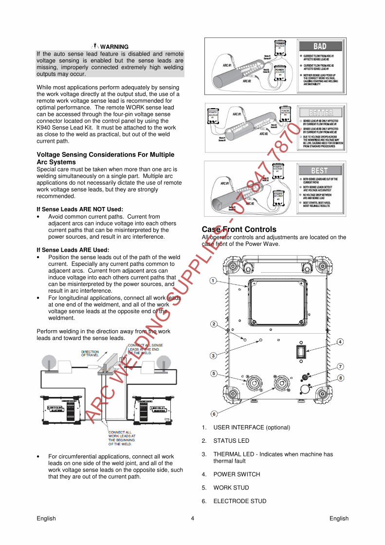
WARNING
If the auto sense lead feature is disabled and remote voltage sensing is enabled but the sense leads are missing, improperly connected extremely high welding outputs may occur. While most applications perform adequately by sensing the work voltage directly at the output stud, the use of a remote work voltage sense lead is recommended for optimal performance. The remote WORK sense lead can be accessed through the four-pin voltage sense connector located on the control panel by using the K940 Sense Lead Kit. It must be attached to the work as close to the weld as practical, but out of the weld current path. Voltage Sensing Considerations For Multiple Arc Systems Special care must be taken when more than one arc is welding simultaneously on a single part. Multiple arc applications do not necessarily dictate the use of remote work voltage sense leads, but they are strongly recommended. If Sense Leads ARE NOT Used: • Avoid common current paths. Current from
adjacent arcs can induce voltage into each others current paths that can be misinterpreted by the power sources, and result in arc interference.
If Sense Leads ARE Used: • Position the sense leads out of the path of the weld
current. Especially any current paths common to adjacent arcs. Current from adjacent arcs can induce voltage into each others current paths that can be misinterpreted by the power sources, and result in arc interference.
• For longitudinal applications, connect all work leads at one end of the weldment, and all of the work voltage sense leads at the opposite end of the weldment.
Perform welding in the direction away from the work leads and toward the sense leads.
• For circumferential applications, connect all work
leads on one side of the weld joint, and all of the work voltage sense leads on the opposite side, such that they are out of the current path.
Case Front Controls All operator controls and adjustments are located on the case front of the Power Wave.
1. USER INTERFACE (optional) 2. STATUS LED 3. THERMAL LED - Indicates when machine has
thermal fault 4. POWER SWITCH 5. WORK STUD 6. ELECTRODE STUD
ARC W
ELDIN
G SUPP
LIES
- 07
847
787
0
English English 5
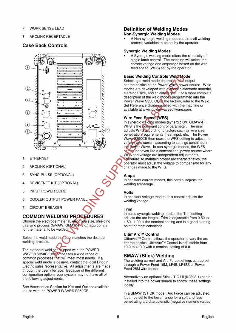
7. WORK SENSE LEAD 8. ARCLINK RECEPTACLE Case Back Controls
1. ETHERNET 2. ARCLINK (OPTIONAL) 3. SYNC-PULSE (OPTIONAL) 4. DEVICENET KIT (OPTIONAL) 5. INPUT POWER CORD 6. COOLER OUTPUT POWER PANEL 7. CIRCUIT BREAKER COMMON WELDING PROCEDURES Choose the electrode material, electrode size, shielding gas, and process (GMAW, GMAW-P etc.) appropriate for the material to be welded. Select the weld mode that best matches the desired welding process. The standard weld set shipped with the POWER WAVE® S350CE encompasses a wide range of common processes that will meet most needs. If a special weld mode is desired, contact the local Lincoln Electric sales representative. All adjustments are made through the user interface. Because of the different configuration options your system may not have all of the following adjustments. See Accessories Section for Kits and Options available to use with the POWER WAVE® S350CE.
Definition of Welding Modes Non-Synergic Welding Modes • A Non-synergic welding mode requires all welding
process variables to be set by the operator. Synergic Welding Modes • A Synergic welding mode offers the simplicity of
single knob control. The machine will select the correct voltage and amperage based on the wire feed speed (WFS) set by the operator.
Basic Welding Controls Weld Mode Selecting a weld mode determines the output characteristics of the Power Wave power source. Weld modes are developed with a specific electrode material, electrode size, and shielding gas. For a more complete description of the weld modes programmed into the Power Wave S350 CE at the factory, refer to the Weld Set Reference Guide supplied with the machine or available at www.powerwavesoftware.com. Wire Feed Speed (WFS) In synergic welding modes (synergic CV, GMAW-P), WFS is the dominant control parameter. The user adjusts WFS according to factors such as wire size, penetration requirements, heat input, etc. The Power Wave S350CE then uses the WFS setting to adjust the voltage and current according to settings contained in the Power Wave. In non-synergic modes, the WFS control behaves like a conventional power source where WFS and voltage are independent adjustments. Therefore, to maintain proper arc characteristics, the operator must adjust the voltage to compensate for any changes made to the WFS. Amps In constant current modes, this control adjusts the welding amperage. Volts In constant voltage modes, this control adjusts the welding voltage. Trim In pulse synergic welding modes, the Trim setting adjusts the arc length. Trim is adjustable from 0.50 to 1.50. 1.00 is the nominal setting and is a good starting point for most conditions. UltimArc™ Control UltimArc™ Control allows the operator to vary the arc characteristics. UltimArc™ Control is adjustable from –10.0 to +10.0 with a nominal setting of 0.0. SMAW (Stick) Welding The welding current and Arc Force settings can be set through a Power Feed 10M, LF45, LF45S or Power Feed 25M wire feeder. Alternatively an optional Stick / TIG UI (K2828-1) can be installed into the power source to control these settings locally. In a SMAW (STICK mode), Arc Force can be adjusted. It can be set to the lower range for a soft and less penetrating arc characteristic (negative numeric values)
ARC W
ELDIN
G SUPP
LIES
- 07
847
787
0
English English 6
or to the higher range (positive numeric values) for a crisp and more penetrating arc. Normally, when welding with cellulosic types of electrodes (E6010, E7010, E6011), a higher energy arc is required to maintain arc stability. This is usually indicated when the electrode sticks to the work-piece or when the arc becomes unstable during manipulative technique. For low hydrogen types of electrodes (E7018, E8018, E9018, etc.) a softer arc is usually desirable and the lower end of the Arc Control suits these types of electrodes. In either case the arc control is available to increase or decrease the energy level delivered to the arc. GTAW (TIG) WELDING The welding current can be set through a Power Feed 10M, LF45, LF45S or Power Feed 25M wire feeder. Alternatively an optional Stick / TIG UI (K2828-1) can be installed into the power source to control these settings locally. The TIG mode features continuous control from 5 to 350A with the use of an optional foot amptrol (K870). The POWER WAVE® S350CE can be run in either a Touch Start TIG mode or Scratch start TIG mode. CONSTANT VOLTAGE WELDING Synergic CV For each wire feed speed, a corresponding voltage is preprogrammed into the machine through special software at the factory. The nominal preprogrammed voltage is the best average voltage for a given wire feed speed, but may be adjusted to preference. When the wire feed speed changes, the POWER WAVE® S350CE automatically adjusts the voltage level correspondingly to maintain similar arc characteristics throughout the WFS range. Non Synergic CV In non-synergic modes, the WFS control behaves more like a conventional CV power source where WFS and voltage are independent adjustments. Therefore to maintain the arc characteristics, the operator must adjust the voltage to compensate for any changes made to the WFS. All CV Modes Pinch adjusts the apparent inductance of the wave shape. The “pinch” function is inversely proportional to inductance. Therefore, increasing Pinch Control greater than 0.0 results in a crisper arc (more spatter) while decreasing the Pinch Control to less than 0.0 provides a softer arc (less spatter). PULSE WELDING Pulse welding procedures are set by controlling an overall “arc length” variable. When pulse welding, the arc voltage is highly dependent upon the waveform. The peak current, back ground current, rise time, fall time and pulse frequency all affect the voltage. The exact voltage for a given wire feed speed can only be
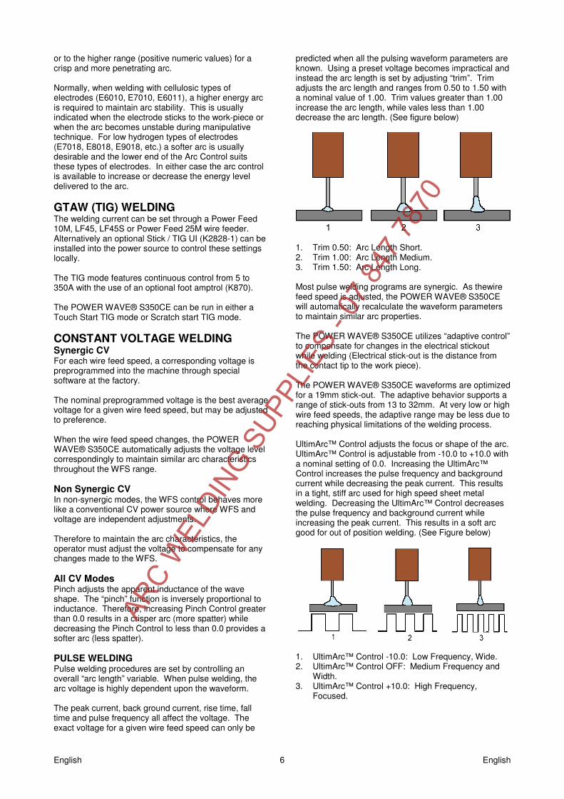
predicted when all the pulsing waveform parameters are known. Using a preset voltage becomes impractical and instead the arc length is set by adjusting “trim”. Trim adjusts the arc length and ranges from 0.50 to 1.50 with a nominal value of 1.00. Trim values greater than 1.00 increase the arc length, while vales less than 1.00 decrease the arc length. (See figure below)
1. Trim 0.50: Arc Length Short. 2. Trim 1.00: Arc Length Medium. 3. Trim 1.50: Arc Length Long. Most pulse welding programs are synergic. As thewire feed speed is adjusted, the POWER WAVE® S350CE will automatically recalculate the waveform parameters to maintain similar arc properties. The POWER WAVE® S350CE utilizes “adaptive control” to compensate for changes in the electrical stickout while welding (Electrical stick-out is the distance from the contact tip to the work piece). The POWER WAVE® S350CE waveforms are optimized for a 19mm stick-out. The adaptive behavior supports a range of stick-outs from 13 to 32mm. At very low or high wire feed speeds, the adaptive range may be less due to reaching physical limitations of the welding process. UltimArc™ Control adjusts the focus or shape of the arc. UltimArc™ Control is adjustable from -10.0 to +10.0 with a nominal setting of 0.0. Increasing the UltimArc™ Control increases the pulse frequency and background current while decreasing the peak current. This results in a tight, stiff arc used for high speed sheet metal welding. Decreasing the UltimArc™ Control decreases the pulse frequency and background current while increasing the peak current. This results in a soft arc good for out of position welding. (See Figure below)
1. UltimArc™ Control -10.0: Low Frequency, Wide. 2. UltimArc™ Control OFF: Medium Frequency and
Width. 3. UltimArc™ Control +10.0: High Frequency,
Focused.
ARC W
ELDIN
G SUPP
LIES
- 07
847
787
0
English English 7
Electromagnetic Compatibility (EMC) 11/04
This machine has been designed in accordance with all relevant directives and standards. However, it may still generate electromagnetic disturbances that can affect other systems like telecommunications (telephone, radio, and television) or other safety systems. These disturbances can cause safety problems in the affected systems. Read and understand this section to eliminate or reduce the amount of electromagnetic disturbance generated by this machine.
This machine has been designed to operate in an industrial area. To operate in a domestic area it is necessary to observe particular precautions to eliminate possible electromagnetic disturbances. The operator must install and operate this equipment as described in this manual. If any electromagnetic disturbances are detected the operator must put in place corrective actions to eliminate these disturbances
with, if necessary, assistance from Lincoln Electric. Before installing the machine, the operator must check the work area for any devices that may malfunction because of electromagnetic disturbances. Consider the following. • Input and output cables, control cables, and telephone cables that are in or adjacent to the work area and the
machine. • Radio and/or television transmitters and receivers. Computers or computer controlled equipment. • Safety and control equipment for industrial processes. Equipment for calibration and measurement. • Personal medical devices like pacemakers and hearing aids. • Check the electromagnetic immunity for equipment operating in or near the work area. The operator must be sure
that all equipment in the area is compatible. This may require additional protection measures. • The dimensions of the work area to consider will depend on the construction of the area and other activities that are
taking place. Consider the following guidelines to reduce electromagnetic emissions from the machine. • Connect the machine to the input supply according to this manual. If disturbances occur if may be necessary to take
additional precautions such as filtering the input supply. • The output cables should be kept as short as possible and should be positioned together. If possible connect the
work piece to ground in order to reduce the electromagnetic emissions. The operator must check that connecting the work piece to ground does not cause problems or unsafe operating conditions for personnel and equipment.
• Shielding of cables in the work area can reduce electromagnetic emissions. This may be necessary for special applications.
ARC W
ELDIN
G SUPP
LIES
- 07
847
787
0
English English 8
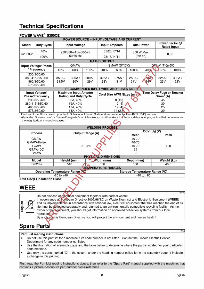
Technical Specifications POWER WAVE® S350CE
POWER SOURCE – INPUT VOLTAGE AND CURRENT
Model Duty Cycle Input Voltage Input Amperes Idle Power Power Factor @ Rated Input
K2823-2 40% 230/380-415/460/575
50/60 Hz 35/20/17/14 300 W Max.
(fan on) 0,95 100% 28/16/14/11
RATED OUTPUT Input Voltage/ Phase
/ Frequency GMAW SMAW (STICK) GTAW (TIG)-DC
40% 60% 100% 40% 60% 100% 40% 60% 100% 230/3/50/60
380-415/3/50/60 460/3/50/60 575/3/50/60
350A / 31,5V
320A / 30V
300A / 29V
325A / 33V
275A / 31V
250A / 31V
350A / 24V
325A / 23V
300A / 22V
RECOMMENDED INPUT WIRE AND FUSES SIZES1 Input Voltage/
Phase/Frequency Maximum Input Ampere Rating and Duty Cycle Cord Size AWG Sizes (mm2) Time Delay Fuse or Breaker
Sizes2 (A) 230/3/50/60
380-415/3/50/60 460/3/50/60 575/3/50/60
35A, 40% 19A, 40% 17A, 40% 14A, 40%
8 (10) 12 (4) 12 (4)
14 (2,5)
45 30 25 20
1 Cord and Fuse Sizes based upon the U.S. National Electric Code and maximum output for 40°C (104°) ambient. 2 Also called “inverse time” or “thermal/magnetic” circuit breakers; circuit breakers that have a delay in tripping action that decreases as
the magnitude of current increases.
WELDING PROCESS
Process Output Range (A) OCV (U0) (V) Mean Peak
GMAW GMAW-Pulse
FCAW GTAW-DC
SMAW
5 - 350
40-70 40-70 40-70
24 60
100
PHYSICAL DIMENSIONS Model Height (mm) Width (mm) Depth (mm) Weight (kg)
K2823-2 518 356 630 46.6 TEMPERATURE RANGES
Operating Temperature Range (ºC) Storage Temperature Range (ºC) -20 to +40 -40 to +80
IP23 155º(F) Insulation Class
WEEE 07/06
Eng
lish
Do not dispose of electrical equipment together with normal waste! In observance of European Directive 2002/96/EC on Waste Electrical and Electronic Equipment (WEEE) and its implementation in accordance with national law, electrical equipment that has reached the end of its life must be collected separately and returned to an environmentally compatible recycling facility. As the owner of the equipment, you should get information on approved collection systems from our local representative. By applying this European Directive you will protect the environment and human health!
Spare Parts 12/05
Part List reading instructions • Do not use this part list for a machine if its code number is not listed. Contact the Lincoln Electric Service
Department for any code number not listed. • Use the illustration of assembly page and the table below to determine where the part is located for your particular
code machine. • Use only the parts marked "X" in the column under the heading number called for in the assembly page (# indicate
a change in this printing). First, read the Part List reading instructions above, then refer to the "Spare Part" manual supplied with the machine, that contains a picture-descriptive part number cross-reference.
ARC W
ELDIN
G SUPP
LIES
- 07
847
787
0

English English 9
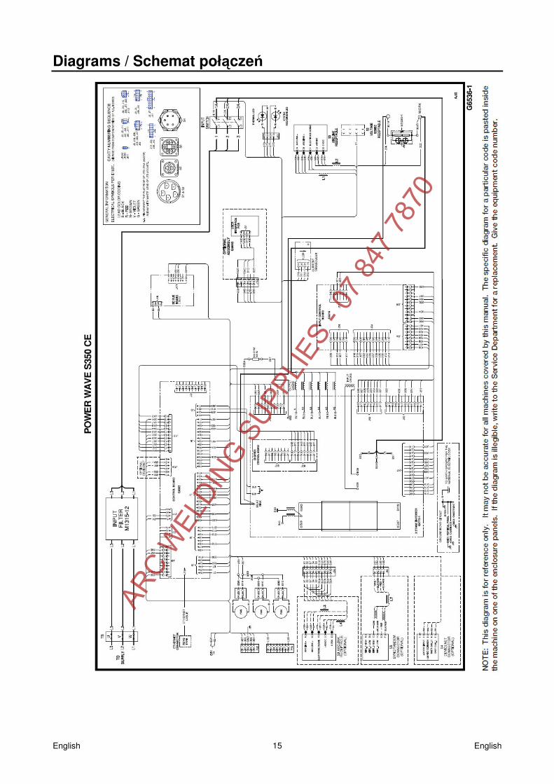
Electrical Schematic Refer to the "Spare Part" manual supplied with the machine.
Accessories Item number Description K14072-1 LF-45 K14083-1 LF-45S K14085-1 CART POWER WAVE S CE K14050-1 Coolarc-50 K10420-1 Coolant Acorox (2x5L) K2921-1 STT module CE K10095-1-15M Remote control 6-pins, 15m K870 Foot Amptrol K2909-1 6-Pin(F) to 12-Pin(M) CE Adapter for Remote Applications - 0,5m K10413-360GC-4M LG360GC 4meter with cross switch K10413-420GC-4M LG420GC 4meter with cross switch K10413-505WC-4M LG505WC 4meter with cross switch K10514-P-8 Push Pull gun Panther CE 8 meter K10514-C-8 Push Pull gun Cougar CE 8 meter See Linc Torch brochure TIG Options See Linc Gun brochure MIG Standard Options
ARC W
ELDIN
G SUPP
LIES
- 07
847
787
0

English English 10
Spare Parts
POWER WAVE® S350CE - Illustration of Sub-Assemblies
POWERWAVE® S350CE
ASSEMBLY PAGE NAME
Cas
e Fr
ont A
ssem
bly
(1
)
Bas
e &
Pow
er C
onve
rsio
n A
ssem
bly
(2)
Div
ider
Pan
el A
ssem
bly
(3)
Out
put C
hoke
Ass
embl
y
(4)
Cas
e B
ack
Ass
embl
y
(5)
Roo
f Ass
embl
y
(6
)
CODE NO.: K NO.: FIGURE NO.: A B C D E F
11625 K2823-2 POWER WAVE® S350 CE 1 1 1 1 1 1
ARC W
ELDIN
G SUPP
LIES
- 07
847
787
0

English English 11
Item Description Part Number Q-ty 1 2 3 4 5 6 7
M15479 Twist Mate Cable Plug 2 X G6094 Wiring Harness (Primary) 1 X S24992-7 Input Power Cord 1 X S28365 Cooler Jumper Harness 1 X M19969-2 Ethernet Patch Cable 1 X
Fig.A : Case Front Assembly (1)
Item Description Part Number Q-ty 1 2 3 4 5 6 7 Case Front Assembly (G6519-1) 1 Case Front G6513-1 1 X
2A P.C. Board Mounting Bracket L13263-1 1 X 3A P.C. Board Mounting Bracket L13263-2 4A Line Switch S20030 1 X 4B Switch Cover S25384-1 1 X 14A LED Lens - Clear, S23093-1 2 X 15A Output Stud M13896-3 2 X 16A Snubber Assembly M20305-1 1 X 17A Control P.C. Board Assembly G5915-[ ] 1 X 30A Cover Plate L15069 1 X 30C UI Trim G6529 1 X 31 Secondary Harness G6792 1 X
31A Sq. Flange Female Receptacle S18657 1 X 31B 5 Pin Connector S12021-73 1 X
Fig. A
ARC W
ELDIN
G SUPP
LIES
- 07
847
787
0

English English 12
Fig.B : Base & Power Conversion Assembly (2) Item Description Part Number Q-ty 1 2 3 4 5 6 7
1 Base Assembly, (G6520-1) NSS 1 X 1A Base L15067-1 1 X 1C Base Extrusion M21251-2 2 X 2A Attachment Kit Bracket L15091 2 X 2C Mounting Foot S28070 4 X 3A Input Choke M22462 1 X 3B Choke Mounting Bracket M22464 1 X 8A Corner Cap L13138 2 X 13A Power Board Bracket M21469-3 1 X 15A Power Conversion Assembly G6037-2 1 X 15B Upper Power Board Bracket M21469-2 1 X 16 Foam M15045-100 3 X
Fig. C : Divider Panel Assembly (3)
Item Description Part Number Q-ty 1 2 3 4 5 6 7
Divider Panel Asbly (G6589-1) NSS 1 X 1 Vertical Divider Panel G6511 1 X
2A Vertical Divider Panel XL15732-[ ] 1 X 3A Cover Plate M22245 1 X 4A CE Filter M18185-12 1 X 5A Control PC Board S28289-[ ] 1 X 7 Bushing T12380-8 1 X 8 Suppressor Assembly (Not Shown) S18858-11 1 X
16 Cable Grommet S18543-4 1 X
Fig. B
Fig. C
ARC W
ELDIN
G SUPP
LIES
- 07
847
787
0
English English 13
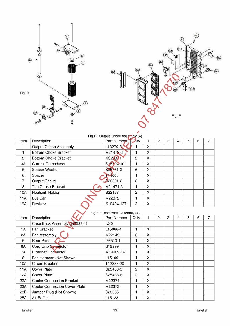
Fig.D : Output Choke Assembly (4) Item Description Part Number Q-ty 1 2 3 4 5 6 7
Output Choke Assembly L13270-3 1 X 1 Bottom Choke Bracket M21472-3 1 X 2 Bottom Choke Bracket XS28371 2 X
3A Current Transducer S18504-10 1 X 5 Spacer Washer S25781-2 6 X 6 Spacer T14605 1 X 7 Output Choke S26801-2 3 X 8 Top Choke Bracket M21471-3 1 X
10A Heatsink Holder S22168 2 X 11A Bus Bar M22372 1 X 19A Resistor S10404-137 3 X
Fig.E : Case Back Assembly (4)
Item Description Part Number Q-ty 1 2 3 4 5 6 7 Case Back Assembly (G6523-1) NSS
1A Fan Bracket L15066-1 1 X 2A Fan Assembly M22149 3 X 5 Rear Panel G6510-1 1 X
6A Cord Grip Connector S19999 1 X 7A Ethernet Connector M19969-14 1 X 8 Fan Harness (Not Shown) L15109 1 X
10A Circuit Breaker T12287-20 1 X 11A Cover Plate S25438-3 2 X 12A Cover Plate S25438-6 2 X 22A Cooler Connection Bracket M22374 1 X 23A Cooler Connection Cover Plate M22373 1 X 23B Jumper Plug (Not Shown) S28365 1 X 25A Air Baffle L15123 1 X
Fig. D
Fig. E
ARC W
ELDIN
G SUPP
LIES
- 07
847
787
0

English English 14
Fig.F : Roof Assembly (6) Item Description Part Number Q-ty 1 2 3 4 5 6 7
1 Roof Assembly M22129-3 1 X 1A Roof L12763-1 1 X 1E Thread Forming Screw (Not Shown) S9225-99 10 X 2 Horizontal Divider Panel M22375 1 X
2A Horizontal Divider Panel L15068-2 1 X 2B Top Extrusion M21251-1 2 X 3A Bracket L15070 2 X 4A Handle G6525-1 2 X 5A Corner Cap L13138 4 X 6 Left Case Side Assembly M22191-1 1 X
6A Left Case Side L13232-3 1 X 7 Right Case Side Assembly M22192-1 1 X
7A Right Case Side L13232-2 1 X
Fig. F
ARC W
ELDIN
G SUPP
LIES
- 07
847
787
0
English English 15
Diagrams / Schemat poł�cze�
ARC W
ELDIN
G SUPP
LIES
- 07
847
787
0