POWER VOLTAGE TRANSFORMERS SSVT
10
Instrument transformers | High voltage POWER VOLTAGE TRANSFORMERS SSVT _UTP Series _UG Series _UTY Series
Transcript of POWER VOLTAGE TRANSFORMERS SSVT

Instrument transformers | High voltage
POWER VOLTAGE TRANSFORMERSSSVT
_UTP Series_UG Series_UTY Series
47Instrument transformers | High voltage
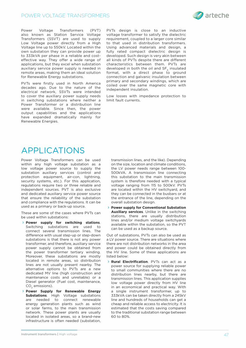
Power Voltage Transformers (PVT) also known as Station Service Voltage Transformers (SSVT) are used to supply Low Voltage power directly from a High Voltage line up to 550kV. Located within the own substation they can provide power up to 333kVA per phase in a reliable and cost-eff ective way. They off er a wide range of applications, but they excel when substation auxiliary service power supply is needed in remote areas, making them an ideal solution for Renewable Energy substations.
PVTs were fi rstly used in North America decades ago. Due to the nature of the electrical network, SSVTs were intended to cover the auxiliary power supply needs in switching substations where neither a Power Transformer or a distribution line were available. Since then, the power output capabilities and the applications have expanded dramatically mainly for Renewable Energies.
POWER VOLTAGE TRANSFORMERS
PVTs design is close to an inductive voltage transformer to satisfy the dielectric requirement, coupled to a larger core similar to that used in distribution transformers. Using advanced materials and design, a fully rated compact dielectric design is developed. Such design is very akin between all kinds of PVTs despite there are diff erent characteristics between them. PVTs are developed in both the oil and SF
6 insulated
format, with a direct phase to ground connection and galvanic insulation between primary and secondary windings, which are coiled over the same magnetic core with independent insulation.
Low losses with impedance protection to limit fault currents.
APPLICATIONSPower Voltage Transformers can be used within any high voltage substation as a low voltage power source to supply the substation auxiliary services (control and protection equipment, air-con, lightning, security systems, etc.). For this application, regulations require two or three reliable and independent sources. PVT is also exclusive and dedicated auxiliary service power source that ensure the reliability of the substation and compliance with the regulations. It can be used as a primary or back-up source.
These are some of the cases where PVTs can be used within substations:
› Power supply for switching stations. Switching substations are used to connect several transmission lines. The diff erence with usual step-up or step-down substations is that there is not any power transformer, and therefore, auxiliary service power supply cannot be obtained from the power transformer tertiary winding. Moreover, these substations are mostly located in remote areas, so distribution lines are not usually present nearby. The alternative options to PVTs are a new dedicated MV line (high construction and maintenance costs and unreliable) or a Diesel generator (Fuel cost, maintenance, CO
2 emissions).
› Power Supply for Renewable Energy Substations. High Voltage substations are needed to connect renewable energy generation plants such as wind or solar farms, to the main transmission network. These power plants are usually located in isolated areas, so a brand-new infrastructure is often needed (substation,
transmission lines, and the like). Depending on the size, location and climate conditions, the LV power needs range between 100-500kVA. A transmission line connecting this substation to the main transmission system is therefore needed with a typical voltage ranging from 115 to 500kV. PVTs are located within the HV switchyard, and they can be connected in the busbars or at the entrance of the line, depending on the overall substation design.
› Power supply for Conventional Substation Auxiliary services. Unlike in the switching stations, there are usually distribution lines and/or medium voltage switchyards available within the substation, so the PVT can be used as a backup source.
Out of substations, PVTs can also be used as a LV power source. There are situations where there are not distribution networks in the area and power could be obtained directly from the HV line. Some of these applications are listed below:
› Rural Electrifi cation. PVTs can act as a power source for supplying reliable power to small communities where there are no distribution lines nearby, but there are transmission lines. This application supplies low voltage power directly from HV line in an economical and practical way. With a single instrument transformer, up to 333kVA can be taken directly from a 245kV line and hundreds of households can get a cheap and reliable access to electricity. It is estimated that the costs saving compared to the traditional substation range between 60 to 80%.

Instrument transformers | High voltage48
POWER VOLTAGE TRANSFORMERS
› Power supply for Telecommunication towers in remote areas. Wide cellphone reception coverage is a demand for telecom companies. Due the relatively short range of each cellphone tower, there is a need to locate many of them in remote locations in order to provide cellphone network coverage to the users (i.e. while traveling along a freeway). Having a nearby transmission line, a PVT can provide the power needed to power up these towers in a reliable and economic way.
› Temporary power supply for under construction substations. Due to the quick erection and location fl exibility, the PVT can be used to get electric supply during the construction and then transferred to another location.
› Mining, oil & gas pumping stations. These locations are usually far from electrical distribution networks, so the PVT can supply power from the transmission line already built to supply power to the site.
› Railway substations.
› Lighting of towers.
› Voltage elevator for High voltage electrical test laboratories, and small wind and solar farms.
_HIGH VOLTAGETRANSMISSION LINES
_SWITCHING ANDPROTECTION ELEMENTS
Power supplyfor
switchingstations
Powersupply for
Telecommunicationtowers in remote
Power supplyfor renewables
controlsystems
RuralElectrification
Temporarypowersupply
_ PVT / SSVT
Oil-paper Gas

49Instrument transformers | High voltage
ADVANTAGES
The conventional solutions used for auxiliary services power supply are a dedicated medium voltage line, diesel generators or the power transformer tertiary winding. ARTECHE’S power voltage transformer has the following advantages:
› Reliable power supply: Since the PVTs are connected in the high voltage switchyard of the substation, there will be power available as long as the line is energized. Since this line is connected to the main transmission system, the power availability is guaranteed.
› Maintenance-free and long-life design.
› Quick commissioning: Delivery time from the factory is similar to the rest of the HV switchyard equipment (circuit breakers, instrument transformers, disconnecting switches or surge arrestors), and the commissioning of the equipment is rela-tively simple, similar to that of instrument transformers. In addition, it can already supply during construction, if the HV line is already energized.
› Reduced environmental impact: PVTs are part of the HV switchyard, so other than that they do not represent any additional environmental impact. This is particu-larly remarkable when they are part of a renewable energy project. The units are hermetically sealed avoiding insulation fl uid leakages to the environment.
› Cost eff ective: Compared to the other alternatives PVTs are in many cases a cost-eff ective solution. Installation costs are generally lower, and the life cost is defi nitely lower, as there is no need to pay for the energy to 3rd parties.
› Robust design. Based on instrument transformers and tested according the same standards to guarantee the same high reliability as any inductive voltage instrument transformer.
› Independent auxiliary services supply. The user does not have to rely on third parties, such as distribution utilities, fuel suppliers, etc.
› Safety and freedom for power trans-former. Power transformer is the core of the substations and LV applications are usually less reliable, therefore there is less operation risks if the tertiary winding is not used for auxiliary services. In addition, if there is already a tertiary winding it can be used for other applications.
› Social benefi t. Rural isolated area electri-fi cation, emergency supply after natural disasters…
› Design fl exibility. Diff erent secondary voltages available. Independent secondary windings. 3-phase/single phase secondary systems using 3, 2 or 1 PVT.
› Self-contained and exclusive power source directly from the transmission line.
› High seismic performance.
› Line Discharge. PVTs can also be used for line discharge, this can be of interest if they are located at the line entrance in the substation.
COMPARISON BETWEEN PVTs AND CONVENTIONAL SOLUTIONS TO SUPPLY AUXILIARY POWER
Initial Cost Life cost Reliability Maintenance Environmental impact Commissioning time Independence
PVT oo - ooo - - o ooo
Distribution Line + Distr. Transformer
ooo o oo o oo ooo o
Diesel Generator o ooo oo oo ooo o o
PT Tertiary oo - ooo o - oo ooo
POWER VOLTAGE TRANSFORMERS

Instrument transformers | High voltage50
Oil-paper insulation: model UTP up to 362 kV and 333 kVA.
POWER VOLTAGE TRANSFORMERS > UTP Series
UTP SERIES
1
2
3
8
7
5
12 11
10
6
1. Oil level indicator2. Primary terminal3. Oil volume compensating system4. Capacitive bushing5. Insulator6. Primary winding7. Core8. Secondary windings9. Secondary terminals10. Secondary terminal box11. Oil sampling valve12. Grounding terminal
4
9

51Instrument transformers | High voltage
PVTs with oil-paper insulation are made with a magnetic core inside a metallic tank with its primary and secondary windings around it. The primary conductor is enclosed by a capacitive bushing consisting of shields and layers of insulating paper fi lled with oil. There is an oil compensating system that eff ectively regulates changes in oil volume mainly caused by temperature. The oil can be analyzed though an oil sampling valve located on the tank.
DESIGN AND MANUFACTURING
POWER VOLTAGE TRANSFORMERS > UTP Series
OPTIONS:
› Porcelain or silicone rubber insulator.
› Terminal for main insulation monitoring (tangent δ measurement).
› Inner temperature monitoring sensor.
› Over-pressure relief valve with connection capability to SCADA system.
› Additional secondaries for measuring and/or protection.
› Taps for voltage regulation.
This series is named with the letters UTP followed by 3 numbers indicating the maximum service voltage for which they have been designed.
The table shows the range currently manufactured by ARTECHE. These characteristics are merely indicative. ARTECHE can manufacture these transformers to comply with any domestic or international standard.
RANGE
Oil-paper insulation > Model UTP
ModelHighest Voltage
(kV)
Rated insulation levelMax.
Power Output
per phase(KVA)
Standard creepage distance
(mm)Power
frequency (kV)
Lightning impulse
(BIL) (kVp)
Switching impulse (kVp)
UTP-123 123 230 550 - 100 4525
UTP-145 145 275 650 - 100 4525
UTP-170 170 325 750 - 100 5285
UTP-245 245395 900
- 333 6125460 1050
UTP-362 362510 1175
950 167 9050575 1300

Instrument transformers | High voltage52
Gas insulation:model UG up to 550 kV and 125 kVA.
POWER VOLTAGE TRANSFORMERS > UG Series
UG SERIES
1. Primary terminal2. Pressure relief device3. HV Electrode4. Insulator5. LV Electrode6. Primary windings7. Secondary windings8. Core9. Secondary terminal box10. Gas fi lling valve
8
3
4
9
1
5
10
2
6
7

53Instrument transformers | High voltage
POWER VOLTAGE TRANSFORMERS > UG Series
PVTs with gas insulation are made with a magnetic core inside a metallic tank with its primary and secondary windings around it. These windings are made of heat-resisting electric wires coated in synthetic resin and a layer of plastic with a high dielectric resistance and excellent thermal and mechanical performance. The SF
6 and this plastic layer
form the electrical insulation. An input valve for SF
6 gas is provided on a side of tank
together with a manometer for monitoring gas pressure.
The silicone rubber insulator guarantees safety during transportation and service.
The transformer is equipped with temperature compensated densimeter with two levels of alarm that can be wired to the control equipment for remote monitoring. In case of a working pressure drop, the PVT can still withstand rated voltage with internal atmospheric gas pressure.
DESIGN AND MANUFACTURINGSafe design, Internal arc class II as per IEC 61869, thanks to:
› Active parts located inside metallic tank, separated from the insulator.
› Pressure relief device located on the upper part.
› Electrical connections resistant to short circuit.
Designed to minimize gas volume, pressure and leaks, with a leakage rate <0.5%/year (lower values available upon request), thus reducing its environmental impact.
Tanks and insulators are designed, manufactured and tested according to international pressure vessel standards.
OPTIONS:
› Inner temperature monitoring sensor.
› Actual pressure value monitoring signal.
› Additional secondaries for measuring and/or protection.
This series is named with the letters UG followed by 2 or 3 numbers indicating the maximum service voltage for which they have been designed.
The table shows the range currently manufactured by ARTECHE. These characteristics are merely indicative. ARTECHE can manufacture these transformers to comply with any domestic or international standard.
RANGE
Gas insulation > Model UG
Model
Highest Voltage
(kV)
Rated insulation levelMax.
Power Output
per phase(KVA)
Standard creepage distance
(mm)Power
frequency(kV)
Lightning impulse
(BIL)(kVp)
Switching Impulse (kVp)
UG-72 72.5 140 325 - 75 1800
UG-145
123 230 550 - 125 3125
145 275 650 - 125 3625
UG-245
170 325 750 - 125 4230
245 460 1050 - 125 6125
300 460 1050 850 125 7350
UG-420
362 510 1175 950 125 9050
420 630 1425 1050 125 10300
UG-550 550 680 1550 1175 125 13750
For detailed values please consult with Arteche.For higher rated power values consult with Arteche.

Instrument transformers | High voltage54
Oil-paper insulation: model UTY up to 245 kV and 16 kVA.
POWER VOLTAGE TRANSFORMERS > UTY Series
UTY SERIES
1. Top cover2. Oil volume compensating system3. Oil level indicator4. Insulator5. Capacitive bushing6. Primary windings7. Secondary windings8. Core9. Insulating oil10. Secondary terminal box11. Grounding terminal
11
10
7
6
8
3
1
2
4
5
9

55Instrument transformers | High voltage
POWER VOLTAGE TRANSFORMERS > UTY Series
PVTs with oil-paper insulation are made with a magnetic core inside a metallic tank with its primary and secondary windings around it. The primary conductor is enclosed by a capacitive bushing consisting of shields and layers of insulating paper fi lled with oil. There is an oil compensating system that eff ectively regulates changes in oil volume mainly caused by temperature. The oil can be analyzed though an oil sampling valve located on the tank.
DESIGN AND MANUFACTURINGOPTIONS:
› Porcelain or silicone rubber insulator.
› Terminal for main insulation monitoring (tangent δ measurement).
This series is named with the letters UTY followed by 2 or 3 numbers indicating the maximum service voltage for which they have been designed.
The table shows the range currently manufactured by ARTECHE. These characteristics are merely indicative. ARTECHE can manufacture these transformers to comply with any domestic or international standard.
RANGE
Oil-paper insulation > Model UTY
ModelHighest Voltage
(kV)
Rated insulation levelMax.
Power Output
per phase(KVA)
Standard creepage distance
(mm)Power
frequency (kV)
Lightning impulse
(BIL) (kVp)
Switching impulse (kVp)
UTY-72 72.5 140 325 - 10 1825
UTY-145 145 275 650 - 16 3625
UTY-245 245 460 1050 - 10 6125