MEDIUM VOLTAGE TRANSFORMERS - metrix-electronics.com · Voltage transformers . Page 8 :...
48
Medium-voltage current transformers Medium-voltage voltage transformers MEDIUM VOLTAGE TRANSFORMERS Low-voltage current transformers GMW – We make your values visible We provide our customers with our products the entire spectrum to solve everything EMAS tasks and thus tools for sustainable use of electrical energy. As a complete provider we also realize the whole project from A to Z, from project consulting to commis- sioning, training and maintenance.
Transcript of MEDIUM VOLTAGE TRANSFORMERS - metrix-electronics.com · Voltage transformers . Page 8 :...

Medium-voltage current transformers
Medium-voltage voltage transformers
MEDIUM VOLTAGE
TRANSFORMERS
Low-voltage current transformers
GMW – We make your values visibleWe provide our customers with our products the entire spectrum to solve everything EMAS tasks and thus tools for sustainable use of electrical energy. As a complete provider we also realize the whole project from A to Z, from project consulting to commis-sioning, training and maintenance.

……………………………………………………………………………………………………………………………………………………………………..............
Page 2 www.g-mw.de
Medium-voltage transformers

……………………………………………………………………………………………………………………………………………………………………………..
www.g-mw.de Page 3
Contents
Technical characteristics From page 4
Current transformers Page 4 Voltage transformers Page 8
Medium-voltage current transformers for indoor usage From page 8
7.2 + 12 kV Support-type current transformer; Narrow type according DIN 42600-8 Page 12 7.2 + 12 kV Support-type current transformer; Elongated version (+ 55 mm) Page 14 7.2 + 12 kV Support-type current transformer; Elongated version (+ 135 mm) Page 16 7.2 + 12 kV Support-type current transformer; Narrow type according DIN 42600-8 with barriers Page 18 7.2 + 12 kV Support-type current transformer; Elongated version (+ 55 mm) with barriers Page 20 24 kV Support-type current transformer; Narrow type according DIN 42600-8 Page 22 24 kV Support-type current transformer; Narrow type according DIN 42600-8 with barriers Page 24 36 kV Support-type current transformer Page 26
Medium-voltage voltage transformers for indoor usage From page 28
7.2 + 12 kV Voltage transformer; single-pole isolated; Narrow type according DIN 42600-9 Page 28 7.2 + 12 kV Voltage transformer; double-pole isolated; Narrow type according DIN 42600-9 Page 30 24 kV Voltage transformer; single-pole isolated; Narrow type according DIN 42600-9 Page 32 24 kV Voltage transformer; double-pole isolated; Narrow type according DIN 42600-9 Page 34 36 kV Voltage transformer; single-pole isolated Seite 36
Low-voltage current transformers for the usage in the isolated area of MV switchgear From page 38
0.72 + 1.2 kV Split-core current transformer for indoor usage Page 38 0.72 + 1.2 kV Single-piece tube current transformer for indoor usage Page 40 0.72 kV Single-piece tube current transformer for indoor usage Page 42
Checklist for medium voltage transformers Page 45
Medium-voltage transformers

……………………………………………………………………………………………………………………………………………………………………..............
Page 4 www.g-mw.de
Medium-voltage transformers
Current transformers – Technical characteristics
Current transformers are special transformers for the proportional transformation of high currents into directly measurable values. Their construction and physical operating principle enables a galvanic separation of the primary circuit from the measured circuit, thereby providing a protection for sequentially connected instruments in the event of a fault.
Primary nominal current Value of the primary current, that characterises the current transformer and for which it is designed.
Secondary nominal current
Value of the secondary current, that characterises the current transformer and for which it is designed.
Actual transformation ratio
Is the ratio of the primary nominal current to the secondary nominal current. It is specified as an unabridged break on the rating plate.
Burden The impedance of the secondary current is declared in ohms and power factor. The burden is usually expressed as the apparent power in volt-amperes, absorbed at a specified power factor and at the rated secondary current.
Rated burden The value of the burden upon which the accurate requirements of this specification are based.
Rated power The value of the apparent power (in [VA] at a specified power factor), which the current transformer is intended to supply to the secondary circuit and rated burden at the rated secondary current.
Nominal frequency Value of the frequency, on which the calculation of the current transformer is based.
Accuracy class The denotation for a current transformer whose measuring deviation remains below the prescribed operating condition.
Phase displacement error [Δφ]
Signifies the phase shift of the primary current and the secondary current. The direction of the indicator is arranged in such a way, that with an optimum produced current transformer the phase displacement error is equal to zero. The phase displacement error is to be regarded as positive when the indicator of the secondary current is ahead compared to the indicator of the primary current. The phase displacement error is specified in minutes or hundredths of a radiant. Note: Strictly speaking this definition is only valid for sinus type currents.
Current error (Transmission error)
Is the percentage deviation of the nominal transmission multiplied by the secondary current from that of the primary current. The current error is calculated positively, should the actual value of the secondary current exceed the nominal value.
Fi = Current error in % Kn = Rated measuring ratio Ip = Primary current in A (effective value) Is = Secondary current in A (effective value)
Max. voltage for electrical equipment Um
This denotes the highest constant permitted value for phase to phase voltage for which the current transformers isolation is rated.

……………………………………………………………………………………………………………………………………………………………………………..
www.g-mw.de Page 5
Total measuring deviation Is the effective value in stationary position, and the difference between: a) The momentary value of the primary current andb) The momentary value of the measuring transmission of the multiplied actual
secondary current, whereby the positive indicators of the primary and secondarycurrent correspond to the accord for the connection denotation.
The total measuring deviation Fg is generally rendered in the percentages of the effective value of the primary current, as per the following mathematical equation:
Kn = Rated measuring transmission Ip = Effective value of the primary current ip = Momentary value of the primary current is = Momentary value of the secondary current T = Duration of period
Rated limit current [Ipl] Value of the lowest primary current where, by the secondary measuring burden, the total deviation of the current transformer for measuring purposes is equal to or greater than 10%.
Over-current rated limiting factor (FS)
Is the ratio of the limit rated current to the primary rated current.
Rated continuous thermal current [Icth]
Is the primary current which allows the continuous operation of the current transformer. When using this current value, the temperature of the secondary wiring must not exceed the prescribed values mentioned in the actual technical norms. This value is in direct relation to the isolation material class.
Thermal rated short-time current [Ith]
This value indicates the effective value of the primary current which the current transformers can withstand with short circuited secondary winding. Other rated measuring values as 1s, e.g. 0.5s, 2s and 3s are acceptable. The thermal short time rated current Ith has to be stated for each current transformer.
Rated surge current [Idyn] Peak value of the primary current, whose electro-mechanical impact is resisted by the current transformer with short circuited secondary winding.
,,Open circuit voltage“ of current transformers
Current transformers, which are not directly encumbered with a burden, have to be generally secondarily short circuited! A secondary open current transformer operates like a loaded one with an almost infinitely high burden. The curve shape of the secondary current is extremely deformed and under certain conditions voltage surges occur up to several kilovolts, which can be harmful to human beings. The amount of the induced “loss motion” depends on the core cross-section and the number of secondary turns.
Earthing of secondary terminals
According to DIN VDE 0141 (01/2000), section 5.3.4, current- and voltage transformers have to be secondarily earthed, starting from Um = 3.6 kV. The design of the earthing connections are mandatory up from series 10N.
Capacitive divider On customer’s request our medium-voltage current transformers CTS12M11(U)-T and CTS24M32(U)-T can be equipped with a capacitive divider according to EN 61243-5. For a simple display of the voltage the capacity C1 of the high-voltage isolation is available at an additional secondary terminal, called Ck. The capacitive voltage tap is designed for the HR-system. When ordering current transformers with capacitive divider, it is required to mention the actual operating voltage UN (Rated voltage), f.e. Um = 24 kV, UN = 20 kV.
Medium-voltage transformers

……………………………………………………………………………………………………………………………………………………………………..............
Page 6 www.g-mw.de
Medium-voltage transformers
Error limits for measuring transformers for classes 0.2…3 according to DIN EN 61869, part 2 At rated frequency and burden between 25 % and 100 % of the rated burden (at cl.3 between 50 % and 100 %) the maximum current error and the phase displacement error (at cl.3, there are no limits for the phase displacement error) may not exceed the values mentioned in the table below. For all classes the burden need to have a power factor of 0.8 inductive and a minimum value of 1 VA, except the burden is lower than 5VA, then a power factor of 1.0 must be used.
Accuracy class
Current error ± F by Phase displacement error ± F by 1.2 In 1.0 In
0.5 In 0.2 In 0.05 In 0.01 In 1.2 In 1.0 In
0.5 In 0.2 In 0.05 In 0.01 In
± % ± % ± % ± % ± % ± min ± min ± min ± min ± min 0.2S 0.2 0.2 0.35 0.75 10 10 15 30 0.2 0.2 0.35 0.75 10 15 30
0.5S 0.5 0.5 0.75 1.5 30 30 45 90 0.5 0.5 0.75 1.5 30 45 90 1 1 1.5 3 60 90 180 3 3 3
Error limit values for current transformers for protection applications At rated frequency and at rated burden the current error, the phase displacement error and the total measuring deviation may not exceed the values mentioned in the table below. For all classes the burden need to have a power factor of 0.8 inductive and a minimum value of 1 VA, except the burden is lower than 5VA, then a power factor of 1.0 must be used.
Accuracy class
Current error ± Fi by Phase displacement error ± Fi by 1.0 In
and thermal nominal continuous current 1.0 In
and thermal nominal continuous current % min
5 P … 1 60 10 P … 3
Current error Fg at nominal error current limit and nominal burden Class 5P … ≤ 5 % Class 10P … ≤ 10 %
Partial discharges Partial discharge requirements are valid for instrument transformers with Um ≥ 7.2 kV.
Partial discharge test voltages and permissible levels
Type of system earthing
Partial discharge test voltage (Effective value)
kV
Permissible partial discharge level2)
pC Type of insulation
liquid insulation solid insulation
Star point grounded1) (Earth fault ≤ 1.5)
Um 1.2 Um / √3
10 5
50 20
Star point isolated or not effectively grounded1)
(Earth fault > 1.5)
1.2 Um 1.2 Um / √3
10 5
50 20
1) If the type of system earthing is not mentioned, the values for the isolated or not effectively grounded star point arehas to be taken.
2) The permissible partial discharge levels are also applicable for frequencies deviating from the nominal ratedfrequency.

……………………………………………………………………………………………………………………………………………………………………………..
www.g-mw.de Page 7
Medium-voltage transformers
Markings of the current transformers connection terminals
The connections of all primary windings are marked with capital letters „P1“ and „P2“. The connections of all secondary windings are marked with the corresponding lower case letters „s1“ and „s2“.
Power requirements of measuring setups
Two main requirements are cited by the user for the principle demands of current transformers:
- a high degree of measuring precision in the range of the nominal current- a protection function in the over-load range
In order to fulfil these demands it is necessary for the assumed nominal power of a current transformer to fully achieve the actual power requirements of the prescribed measurements. In ascertaining the actual power requirements, consideration is to be given to the power losses of the appliances to be connected, as well as to the losses of the measuring conductor.
The actual power consumption of the connected devices can be found in the respective data sheets.
Please note: If the power requirement of the measuring setup is substantially less than the power supply of the current transformer, the CT loses his protective function in over-current ranges. In some cases this can lead to a damage of the connected devices.
Power consumption of copper wires
Is = Secondary nominal current [A] I = Distance in m Acu = Wire cross section in mm² Pv = Power loss of the measuring conductor
Comment: With a joint three phase current return conductor the values of Pv are halved.
Chart for values referring to 5 A
Nominal cross section 1 m 2 m 3 m 4 m 5 m 6 m 7 m 8 m 9 m 10 m 2.5 mm² 0.36 0.71 1.07 1.43 1.78 2.14 2.50 2.86 3.21 3.57 4.0 mm² 0.22 0.45 0.67 0.89 1.12 1.34 1.56 1.79 2.01 2.24 6.0 mm² 0.15 0.30 0.45 0.60 0.74 0.89 1.04 1.19 1.34 1.49 10.0 mm² 0.09 0.18 0.27 0.36 0.44 0.54 0.63 0.71 0.80 0.89
Chart for values referring to 1 A
Nominal cross section 10 m 20 m 30 m 40 m 50 m 60 m 70 m 80 m 90 m 100 m 1.0 mm² 0.36 0.71 1.07 1.43 1.78 2.14 2.50 2.86 3.21 3.57 2.5 mm² 0.14 0.29 0.43 0.57 0.72 0.86 1.00 1.14 1.29 1.43 4.0 mm² 0.09 0.18 0.27 0.36 0.45 0.54 0.63 0.71 0.80 0.89 6.0 mm² 0.06 0.12 0.18 0.24 0.30 0.36 0.42 0.48 0.54 0.60 10.0 mm² 0.04 0.07 0.11 0.14 0.18 0.21 0.25 0.29 0.32 0.36

……………………………………………………………………………………………………………………………………………………………………..............
Page 8 www.g-mw.de
Medium-voltage transformers
Voltage transformers – Technical characteristics Voltage transformers are special transformers fort he proportional transformation of high primary voltages into directly measurable, smaller secondary voltages. Their construction and physical operating principle enables a galvanic separation of the primary circuit from the measured circuit, thereby providing a protection for sequentially connected instruments in the event of a fault.
Single-pole isolated voltage transformers
Single-phase voltage transformer for phase-to-ground voltage. One end of the primary winding is provided for direct earthing.
Double-pole isolated voltage transformers
Voltage transformers for phase-to-phase voltage, in which all parts of the primary winding, including the terminals are isolated against earth.
Winding for earth fault detection
Winding of a single-phase voltage transformer, which is provided in a set of three single-phase VTs for connection in the open delta, to
a) create a residual voltage at earth fault conditionsb) damp ferro-resonances
Please note: When connecting in open delta the winding of only one voltage transformer may be connected to ground, because otherwise the VTs are short-circuited.
Primary + secondary rated voltage
Value of the primary and secondary voltage, which is mentioned on the rating plate of the voltage transformer, and on which its operating characteristic is based.
Actual transformation ratio
Is the ratio of the primary nominal voltage to the secondary nominal voltage. It is specified as an unabridged break on the rating plate.
Burden The impedance of the secondary voltage is declared in ohms and power factor. The burden is usually expressed as the apparent power in volt-amperes, absorbed at a specified power factor and at the rated secondary voltage.
Rated burden The value of the burden upon which the accurate requirements of this specification are based.
Rated power The value of the apparent power (in [VA] at a specified power factor), which the voltage transformer is intended to supply to the secondary circuit and rated burden at the rated secondary voltage.
Nominal frequency Value of the frequency, on which the calculation of the voltage transformer is based.
Accuracy class The denotation for a voltage transformer whose measuring deviation remains below the prescribed operating condition.
Phase displacement error [Δφ]
Signifies the phase shift of the primary voltage and the secondary voltage. The direction of the indicator is arranged in such a way, that with an optimum produced voltage transformer the phase displacement error is equal to zero.
Voltage error (Transmission error)
Measurement error, caused by a voltage transformer, which are a result of the difference between the actual ratio of the voltage transformer and the rated ratio. The voltage error (in %) is calculated according to the following formula:
εu = Voltage error in % kr = Rated transformation ratio Up = Actual primary voltage Us = Actual secondary volage, when Up flows under measurement conditions

……………………………………………………………………………………………………………………………………………………………………………..
www.g-mw.de Page 9
Medium-voltage transformers
Highest voltage for equipment Um
RMS (kV) of the highest phase-to-phase voltage for which a instrument transformer is dimensioned in terms of its isolation.
Rated voltage factor [FV] Multiplication factor to be applied to the primary rated voltage, to determine the highest voltage at which the voltage transformer has to correspond to the thermal requirements and the requirements of the measuring accuracy for a specified time period. Single-pole isolate voltage transformers have usually a rated voltage factor of 1.9 ∙ UN / 8h, all other voltage transformers have a rated voltage factor of 1.2 ∙ UN / continuously.
Thermal power Value of the apparent power at rated voltage, which can be loaded on the secondary winding, without exceeding the limits of overtemperature.
Operation of voltage transformers
Voltage transformers must not be short circuited on the secondary side! The grounding terminal of the primary winding (N) has to be effectively earthed and must not be removed during operation.
Earthing of secondary terminals
According to DIN VDE 0141 (01/2000), section 5.3.4, current- and voltage transformers have to be secondarily earthed, starting from Um = 3.6 kV. The design of the earthing connections are mandatory up from series 10N.
Error limits for voltage transformers for classes 0.2…3 according to DIN EN 61869, part 3
At rated frequency and burden between 25 % and 100 % of the rated burden and at a power factor of cos β = 0,8 (inductive) the voltage error and the phase displacement error may not exceed the values mentioned in the table below for primary voltage between 80 % and 120 % of the rated primary voltage.
Accuracy class Voltage error εu Phase displacement error ± F by ± % ± min
0.2 0.2 10 0.5 0.5 20 1 1.0 40 3 3.0 -
Error limit values for voltage transformers for protection applications
At rated frequency and burden between 25 % and 100 % of the rated burden and at a power factor of cos β = 0,8 (inductive) the voltage error and the phase displacement error may not exceed the values mentioned in the table below for primary voltage of 5 % of the rated primary voltage and for rated primary voltage multiplied with the rated voltage factor. At 2 % of the rated primary voltage the limits of the voltage error and of the phase displacement error are twice as high as mentioned in below table.
Accuracy class Voltage error εu Phase displacement error φ ± % ± min
3P 3,0 120 6P 6,0 240

……………………………………………………………………………………………………………………………………………………………………..............
Page 10 www.g-mw.de
Medium-voltage transformers
Partial discharges Partial discharge requirements are valid for instrument transformers with Um ≥ 7.2 kV.
Partial discharge test voltages and permissible levels for voltage transformers
Type of system earthing
Type of voltage
transformer
Partial discharge test voltage (effective value)
kV
Permissible partial discharge level2)
pC Type of insulation
Liquid- or gas isolation solid isolation
Star point grounded1) (Earth fault ≤ 1.4)
single-pole isolated
Um 1.2 Um / √3
10 5
50 20
Star point grounded1) (Earth fault ≤ 1.4)
double-pole isolated 1.2 Um 5 20
Star point isolated or not effectively grounded1)
(Earth fault > 1.4)
single-pole isolated
1.2 Um 1.2 Um / √3
10 5
50 20
Star point isolated or not effectively grounded1)
(Earth fault > 1.4)
double-pole isolated 1.2 Um 5 20
1) If the type of system earthing is not mentioned, the values for the isolated or not effectively grounded star point arehas to be taken.
2) The permissible partial discharge levels are also applicable for frequencies deviating from the nominal ratedfrequency.
Markings of the voltage transformers connection terminals
The connections of the primary windings are marked with capital letters „A“, „B“ and „N“. The connections of the secondary terminals are marked with the corresponding lower case letters “a”, “b” and “n”. The letters “A” and “B” indicate the fully isolated connections and the letter “N” indicated the terminal, which is provided for earthing. The isolation of “N” is lower than the isolation of the other connections.
The marking „da“ and „dn“ denotes the terminal of the winding for earth fault detection.

……………………………………………………………………………………………………………………………………………………………………………..
www.g-mw.de Page 11
Medium-voltage transformers

……………………………………………………………………………………………………………………………………………………………………..............
Page 12 www.g-mw.de
Medium-voltage transformers
Support type current transformers for indoor application 7.2 kV and 12 kV – Narrow type according to DIN 42600, part 8
Description:
Medium-voltage current transformers for indoor application, which are converting multiple primary currents proportional and in-phase into measurable and standardized secondary currents. These transformers are fully resin-hardened in polyurethane and are serving apart of their main function as a current transformer as well as a bus bar support. These CTs are applicable both for measuring and protection purposes. The medium-voltage current transformers are also available as multicore current transformers. The maximum quantity of cores depends on the chosen burden and accuracy class.
Optionally, the current transformers are available with primary or secondary reconnection. At the primary reconnectable current transformers it is possible to choose between two primary nominal currents, depending if the connection is made in parallel or in series. The primary nominal currents can only be realized in ratio 1:2. At the secondary reconnectable current transformers the reconnection is realized by means of one or more secondary taps. Thereby the primary nominal current can be realized in various ratios.
Technical data:
CTS12M11-T CTS12M11U-T (primary reconnectable)
CTS12M11-T (secondary reconnectable)
Max. operating voltage Um: 12 kV 12 kV 12 kV Power frequency voltage: 28 kV 28 kV 28 kV Lightning impulse voltage: 75 kV 75 kV 75 kV Therm. nominal continuous rated current Icth:
1.2 x IN 1.2 x IN 1.2 x IN
Therm. rated short-time current Ith: 100 x IN, 1 sec.;
max. 40 kA, 1 sec. 100 x IN, 1 sec.;
max. 40 kA, 1 sec. 100 x IN, 1 sec.;
max. 40 kA, 1 sec. Rated surge current Idyn: 2.5 x Ith 2.5 x Ith 2.5 x Ith Primary nominal current: 5 A – 3000 A 2x5 A – 2x600 A …-5 A – 3000-… A Secondary nominal current: 5 A or 1 A 5 A or 1 A 5 A or 1 A Nominal frequency: 50 / 60 Hz 50 / 60 Hz 50 / 60 Hz Measuring CT accuracy classes: 1; 0.5; 0.5S; 0.2; 0.2S 1; 0.5; 0.5S; 0.2; 0.2S 1; 0.5; 0.5S; 0.2; 0.2S
Protection CT accuracy classes: 5P5; 5P10; 5P20; 5P30; 10P5; 10P10; 10P20; 10P30
5P5; 5P10; 5P20; 5P30; 10P5; 10P10; 10P20; 10P30
5P5; 5P10; 5P20; 5P30; 10P5; 10P10; 10P20; 10P30
Capacitive divider: Available on request Available on request Available on request Insulation class: E E E Cantilever strength: 5000 Nm 5000 Nm 5000 Nm Weight: approx. 22 kg approx. 22 kg approx. 22 kg
Subject to technical modifications without notice Please note, that the above mentioned data are standard values. Other values on request.

……………………………………………………………………………………………………………………………………………………………………………..
www.g-mw.de Page 13
Medium-voltage transformers
Drawings:
Primary connections:
up to 1250 A: Primary reconnectable up to 1200 A:
< 1250 A up to 3000 A: Terminal assignment – Primary reconnection:

……………………………………………………………………………………………………………………………………………………………………..............
Page 14 www.g-mw.de
Medium-voltage transformers
Support type current transformers for indoor application 7.2 kV and 12 kV – elongated by 55mm for increased demands
Description:
Medium-voltage current transformers for indoor application, which are converting multiple primary currents proportional and in-phase into measurable and standardized secondary currents. These transformers are fully resin-hardened in polyurethane and are serving apart of their main function as a current transformer as well as a bus bar support. These CTs are applicable both for measuring and protection purposes. The medium-voltage current transformers are also available as multicore current transformers. The maximum quantity of cores depends on the chosen burden and accuracy class.
Optionally, the current transformers are available with primary or secondary reconnection. At the primary reconnectable current transformers it is possible to choose between two primary nominal currents, depending if the connection is made in parallel or in series. The primary nominal currents can only be realized in ratio 1:2. At the secondary reconnectable current transformers the reconnection is realized by means of one or more secondary taps. Thereby the primary nominal current can be realized in various ratios.
Technical data:
CTS12L11-T CTS12L11U-T (primary reconnectable)
CTS12L11-T (secondary reconnectable)
Max. operating voltage Um: 12 kV 12 kV 12 kV Power frequency voltage: 28 kV 28 kV 28 kV Lightning impulse voltage: 75 kV 75 kV 75 kV Therm. nominal continuous rated current Icth:
1.2 x IN 1.2 x IN 1.2 x IN
Therm. rated short-time current Ith: 100 x IN, 1 sec.;
max. 40 kA, 1 sec. 100 x IN, 1 sec.;
max. 40 kA, 1 sec. 100 x IN, 1 sec.;
max. 40 kA, 1 sec. Rated surge current Idyn: 2.5 x Ith 2.5 x Ith 2.5 x Ith Primary nominal current: 5 A – 3000 A 2x5 A – 2x600 A …-5 A – 3000-… A Secondary nominal current: 5 A or 1 A 5 A or 1 A 5 A or 1 A Nominal frequency: 50 / 60 Hz 50 / 60 Hz 50 / 60 Hz Measuring CT accuracy classes: 1; 0.5; 0.5S; 0.2; 0.2S 1; 0.5; 0.5S; 0.2; 0.2S 1; 0.5; 0.5S; 0.2; 0.2S
Protection CT accuracy classes: 5P5; 5P10; 5P20; 5P30; 10P5; 10P10; 10P20; 10P30
5P5; 5P10; 5P20; 5P30; 10P5; 10P10; 10P20; 10P30
5P5; 5P10; 5P20; 5P30; 10P5; 10P10; 10P20; 10P30
Insulation class: E E E Cantilever strength: 5000 Nm 5000 Nm 5000 Nm Weight: approx. 35 kg approx. 35 kg approx. 35 kg
Subject to technical modifications without notice Please note, that the above mentioned data are standard values. Other values on request.

……………………………………………………………………………………………………………………………………………………………………………..
www.g-mw.de Page 15
Medium-voltage transformers
Drawings:
Primary connections:
up to 1250 A: Primary reconnectable up to 1200 A:
< 1250 A up to 3000 A: Terminal assignment – Primary reconnection:

……………………………………………………………………………………………………………………………………………………………………..............
Page 16 www.g-mw.de
Medium-voltage transformers
Support type current transformers for indoor application 7.2 kV and 12 kV – elongated by 135mm for increased demands and up to 6 measuring-
or protection cores
Description:
Medium-voltage current transformers for indoor application, which are converting multiple primary currents proportional and in-phase into measurable and standardized secondary currents. These transformers are fully resin-hardened in polyurethane and are serving apart of their main function as a current transformer as well as a bus bar support. These CTs are applicable both for measuring and protection purposes. The medium-voltage current transformers are also available as multicore current transformers. The maximum quantity of cores depends on the chosen burden and accuracy class.
Optionally, the current transformers are available with primary or secondary reconnection. At the primary reconnectable current transformers it is possible to choose between two primary nominal currents, depending if the connection is made in parallel or in series. The primary nominal currents can only be realized in ratio 1:2. At the secondary reconnectable current transformers the reconnection is realized by means of one or more secondary taps. Thereby the primary nominal current can be realized in various ratios.
Technical data:
CTS12XL11-T CTS12XL11U-T (primary reconnectable)
CTS12XL11-T (secondary reconnectable)
Max. operating voltage Um: 12 kV 12 kV 12 kV Power frequency voltage: 28 kV 28 kV 28 kV Lightning impulse voltage: 75 kV 75 kV 75 kV Therm. nominal continuous rated current Icth:
1.2 x IN 1.2 x IN 1.2 x IN
Therm. rated short-time current Ith: 100 x IN, 1 sec.;
max. 40 kA, 1 sec. 100 x IN, 1 sec.;
max. 40 kA, 1 sec. 100 x IN, 1 sec.;
max. 40 kA, 1 sec. Rated surge current Idyn: 2.5 x Ith 2.5 x Ith 2.5 x Ith Primary nominal current: 5 A – 3000 A 2x5 A – 2x600 A …-5 A – 3000-… A Secondary nominal current: 5 A or 1 A 5 A or 1 A 5 A or 1 A Nominal frequency: 50 / 60 Hz 50 / 60 Hz 50 / 60 Hz Measuring CT accuracy classes: 1; 0.5; 0.5S; 0.2; 0.2S 1; 0.5; 0.5S; 0.2; 0.2S 1; 0.5; 0.5S; 0.2; 0.2S
Protection CT accuracy classes: 5P5; 5P10; 5P20; 5P30; 10P5; 10P10; 10P20; 10P30
5P5; 5P10; 5P20; 5P30; 10P5; 10P10; 10P20; 10P30
5P5; 5P10; 5P20; 5P30; 10P5; 10P10; 10P20; 10P30
Insulation class: E E E Cantilever strength: 5000 Nm 5000 Nm 5000 Nm Weight: approx. 45 kg approx. 45 kg approx. 45 kg
Subject to technical modifications without notice Please note, that the above mentioned data are standard values. Other values on request.
……………………………………………………………………………………………………………………………………………………………………………..
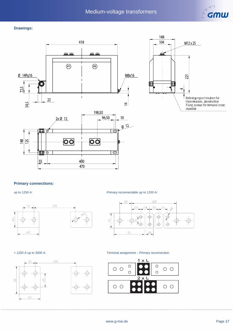
www.g-mw.de Page 17
Medium-voltage transformers
Drawings:
Primary connections:
up to 1250 A: Primary reconnectable up to 1200 A:
< 1250 A up to 3000 A: Terminal assignment – Primary reconnection:

……………………………………………………………………………………………………………………………………………………………………..............
Page 18 www.g-mw.de
Support type current transformers for indoor application 7.2 kV and 12 kV – Narrow type according to DIN 42600, part 8 with barriers
Description:
Medium-voltage current transformers for indoor application, which are converting multiple primary currents proportional and in-phase into measurable and standardized secondary currents. These transformers are fully resin-hardened in polyurethane and are serving apart of their main function as a current transformer as well as a bus bar support. These CTs are applicable both for measuring and protection purposes. The medium-voltage current transformers are also available as multicore current transformers. The maximum quantity of cores depends on the chosen burden and accuracy class.
Optionally, the current transformers are available with primary or secondary reconnection. At the primary reconnectable current transformers it is possible to choose between two primary nominal currents, depending if the connection is made in parallel or in series. The primary nominal currents can only be realized in ratio 1:2. At the secondary reconnectable current transformers the reconnection is realized by means of one or more secondary taps. Thereby the primary nominal current can be realized in various ratios.
Technical data:
CTS12M11B-T CTS12M11BU-T (primary reconnectable)
CTS12M11B-T (secondary reconnectable)
Max. operating voltage Um: 12 kV 12 kV 12 kV Power frequency voltage: 28 kV 28 kV 28 kV Lightning impulse voltage: 75 kV 75 kV 75 kV Therm. nominal continuous rated current Icth:
1.2 x IN 1.2 x IN 1.2 x IN
Therm. rated short-time current Ith: 100 x IN, 1 sec.;
max. 40 kA, 1 sec. 100 x IN, 1 sec.;
max. 40 kA, 1 sec. 100 x IN, 1 sec.;
max. 40 kA, 1 sec. Rated surge current Idyn: 2.5 x Ith 2.5 x Ith 2.5 x Ith Primary nominal current: 5 A – 3000 A 2x5 A – 2x600 A …-5 A – 3000-… A Secondary nominal current: 5 A or 1 A 5 A or 1 A 5 A or 1 A Nominal frequency: 50 / 60 Hz 50 / 60 Hz 50 / 60 Hz Measuring CT accuracy classes: 1; 0.5; 0.5S; 0.2; 0.2S 1; 0.5; 0.5S; 0.2; 0.2S 1; 0.5; 0.5S; 0.2; 0.2S
Protection CT accuracy classes: 5P5; 5P10; 5P20; 5P30; 10P5; 10P10; 10P20; 10P30
5P5; 5P10; 5P20; 5P30; 10P5; 10P10; 10P20; 10P30
5P5; 5P10; 5P20; 5P30; 10P5; 10P10; 10P20; 10P30
Insulation class: E E E Cantilever strength: 5000 Nm 5000 Nm 5000 Nm Weight: approx. 23 kg approx. 23 kg approx. 23 kg
Subject to technical modifications without notice Please note, that the above mentioned data are standard values. Other values on request.
Medium-voltage transformers

……………………………………………………………………………………………………………………………………………………………………………..
www.g-mw.de Page 19
Medium-voltage transformers
Drawings: Primary connections: up to 1250 A: Primary reconnectable up to 1200 A: < 1250 A up to 3000 A: Terminal assignment – Primary reconnection:
……………………………………………………………………………………………………………………………………………………………………..............
Page 20 www.g-mw.de
Medium-voltage transformers
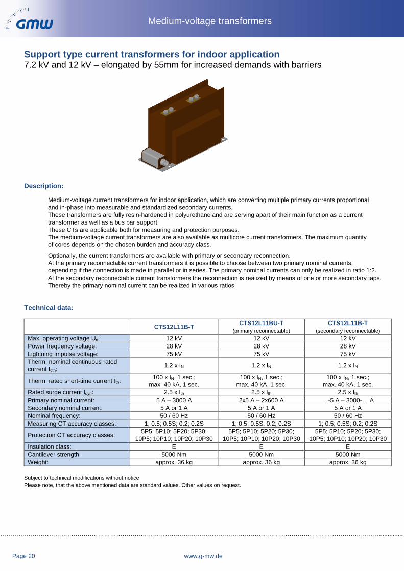
Support type current transformers for indoor application 7.2 kV and 12 kV – elongated by 55mm for increased demands with barriers
Description:
Medium-voltage current transformers for indoor application, which are converting multiple primary currents proportional and in-phase into measurable and standardized secondary currents. These transformers are fully resin-hardened in polyurethane and are serving apart of their main function as a current transformer as well as a bus bar support. These CTs are applicable both for measuring and protection purposes. The medium-voltage current transformers are also available as multicore current transformers. The maximum quantity of cores depends on the chosen burden and accuracy class.
Optionally, the current transformers are available with primary or secondary reconnection. At the primary reconnectable current transformers it is possible to choose between two primary nominal currents, depending if the connection is made in parallel or in series. The primary nominal currents can only be realized in ratio 1:2. At the secondary reconnectable current transformers the reconnection is realized by means of one or more secondary taps. Thereby the primary nominal current can be realized in various ratios.
Technical data:
CTS12L11B-T CTS12L11BU-T (primary reconnectable)
CTS12L11B-T (secondary reconnectable)
Max. operating voltage Um: 12 kV 12 kV 12 kV Power frequency voltage: 28 kV 28 kV 28 kV Lightning impulse voltage: 75 kV 75 kV 75 kV Therm. nominal continuous rated current Icth:
1.2 x IN 1.2 x IN 1.2 x IN
Therm. rated short-time current Ith: 100 x IN, 1 sec.;
max. 40 kA, 1 sec. 100 x IN, 1 sec.;
max. 40 kA, 1 sec. 100 x IN, 1 sec.;
max. 40 kA, 1 sec. Rated surge current Idyn: 2.5 x Ith 2.5 x Ith 2.5 x Ith Primary nominal current: 5 A – 3000 A 2x5 A – 2x600 A …-5 A – 3000-… A Secondary nominal current: 5 A or 1 A 5 A or 1 A 5 A or 1 A Nominal frequency: 50 / 60 Hz 50 / 60 Hz 50 / 60 Hz Measuring CT accuracy classes: 1; 0.5; 0.5S; 0.2; 0.2S 1; 0.5; 0.5S; 0.2; 0.2S 1; 0.5; 0.5S; 0.2; 0.2S
Protection CT accuracy classes: 5P5; 5P10; 5P20; 5P30; 10P5; 10P10; 10P20; 10P30
5P5; 5P10; 5P20; 5P30; 10P5; 10P10; 10P20; 10P30
5P5; 5P10; 5P20; 5P30; 10P5; 10P10; 10P20; 10P30
Insulation class: E E E Cantilever strength: 5000 Nm 5000 Nm 5000 Nm Weight: approx. 36 kg approx. 36 kg approx. 36 kg
Subject to technical modifications without notice Please note, that the above mentioned data are standard values. Other values on request.

……………………………………………………………………………………………………………………………………………………………………………..
www.g-mw.de Page 21
Medium-voltage transformers
Drawings:
Primary connections:
up to 1250 A: Primary reconnectable up to 1200 A:
< 1250 A up to 3000 A: Terminal assignment – Primary reconnection:

……………………………………………………………………………………………………………………………………………………………………..............
Page 22 www.g-mw.de
Medium-voltage transformers
Support type current transformers for indoor application 24 kV – Narrow type according to DIN 42600, part 8
Description:
Medium-voltage current transformers for indoor application, which are converting multiple primary currents proportional and in-phase into measurable and standardized secondary currents. These transformers are fully resin-hardened in polyurethane and are serving apart of their main function as a current transformer as well as a bus bar support. These CTs are applicable both for measuring and protection purposes. The medium-voltage current transformers are also available as multicore current transformers. The maximum quantity of cores depends on the chosen burden and accuracy class.
Optionally, the current transformers are available with primary or secondary reconnection. At the primary reconnectable current transformers it is possible to choose between two primary nominal currents, depending if the connection is made in parallel or in series. The primary nominal currents can only be realized in ratio 1:2. At the secondary reconnectable current transformers the reconnection is realized by means of one or more secondary taps. Thereby the primary nominal current can be realized in various ratios.
Technical data:
CTS24M32-T CTS24M32U-T (primary reconnectable)
CTS12M11-T (secondary reconnectable)
Max. operating voltage Um: 24 kV 24 kV 24 kV Power frequency voltage: 50 kV 50 kV 50 kV Lightning impulse voltage: 125 kV 125 kV 125 kV Therm. nominal continuous rated current Icth:
1.2 x IN 1.2 x IN 1.2 x IN
Therm. rated short-time current Ith: 100 x IN, 1 sec.;
max. 40 kA, 1 sec. 100 x IN, 1 sec.;
max. 40 kA, 1 sec. 100 x IN, 1 sec.;
max. 40 kA, 1 sec. Rated surge current Idyn: 2.5 x Ith 2.5 x Ith 2.5 x Ith Primary nominal current: 5 A – 1600 A 2x5 A – 2x600 A …-5 A – 1600-… A Secondary nominal current: 5 A or 1 A 5 A or 1 A 5 A or 1 A Nominal frequency: 50 / 60 Hz 50 / 60 Hz 50 / 60 Hz Measuring CT accuracy classes: 1; 0.5; 0.5S; 0.2; 0.2S 1; 0.5; 0.5S; 0.2; 0.2S 1; 0.5; 0.5S; 0.2; 0.2S
Protection CT accuracy classes: 5P5; 5P10; 5P20; 5P30; 10P5; 10P10; 10P20; 10P30
5P5; 5P10; 5P20; 5P30; 10P5; 10P10; 10P20; 10P30
5P5; 5P10; 5P20; 5P30; 10P5; 10P10; 10P20; 10P30
Capacitive divider: Available on request Available on request Available on request Insulation class: E E E Cantilever strength: 5000 Nm 5000 Nm 5000 Nm Weight: approx. 28 kg approx. 28 kg approx. 28 kg
Subject to technical modifications without notice Please note, that the above mentioned data are standard values. Other values on request.

……………………………………………………………………………………………………………………………………………………………………………..
www.g-mw.de Page 23
Medium-voltage transformers
Drawings: Primary connections: up to 1250 A: Primary reconnectable up to 1200 A:
< 1250 A up to 3000 A: Terminal assignment – Primary reconnection:

……………………………………………………………………………………………………………………………………………………………………..............
Page 24 www.g-mw.de
Medium-voltage transformers
Support type current transformers for indoor application 24 kV – Narrow type according to DIN 42600, part 8 with barriers
Description:
Medium-voltage current transformers for indoor application, which are converting multiple primary currents proportional and in-phase into measurable and standardized secondary currents. These transformers are fully resin-hardened in polyurethane and are serving apart of their main function as a current transformer as well as a bus bar support. These CTs are applicable both for measuring and protection purposes. The medium-voltage current transformers are also available as multicore current transformers. The maximum quantity of cores depends on the chosen burden and accuracy class.
Optionally, the current transformers are available with primary or secondary reconnection. At the primary reconnectable current transformers it is possible to choose between two primary nominal currents, depending if the connection is made in parallel or in series. The primary nominal currents can only be realized in ratio 1:2. At the secondary reconnectable current transformers the reconnection is realized by means of one or more secondary taps. Thereby the primary nominal current can be realized in various ratios.
Technical data:
CTS24M32B-T CTS24M32BU-T (primary reconnectable)
CTS12M11B-T (secondary reconnectable)
Max. operating voltage Um: 24 kV 24 kV 24 kV Power frequency voltage: 50 kV 50 kV 50 kV Lightning impulse voltage: 125 kV 125 kV 125 kV Therm. nominal continuous rated current Icth:
1.2 x IN 1.2 x IN 1.2 x IN
Therm. rated short-time current Ith: 100 x IN, 1 sec.;
max. 40 kA, 1 sec. 100 x IN, 1 sec.;
max. 40 kA, 1 sec. 100 x IN, 1 sec.;
max. 40 kA, 1 sec. Rated surge current Idyn: 2.5 x Ith 2.5 x Ith 2.5 x Ith Primary nominal current: 5 A – 1600 A 2x5 A – 2x600 A …-5 A – 1600-… A Secondary nominal current: 5 A or 1 A 5 A or 1 A 5 A or 1 A Nominal frequency: 50 / 60 Hz 50 / 60 Hz 50 / 60 Hz Measuring CT accuracy classes: 1; 0.5; 0.5S; 0.2; 0.2S 1; 0.5; 0.5S; 0.2; 0.2S 1; 0.5; 0.5S; 0.2; 0.2S
Protection CT accuracy classes: 5P5; 5P10; 5P20; 5P30; 10P5; 10P10; 10P20; 10P30
5P5; 5P10; 5P20; 5P30; 10P5; 10P10; 10P20; 10P30
5P5; 5P10; 5P20; 5P30; 10P5; 10P10; 10P20; 10P30
Insulation class: E E E Cantilever strength: 5000 Nm 5000 Nm 5000 Nm Weight: approx. 29 kg approx. 29 kg approx. 29 kg
Subject to technical modifications without notice Please note, that the above mentioned data are standard values. Other values on request.

……………………………………………………………………………………………………………………………………………………………………………..
www.g-mw.de Page 25
Medium-voltage transformers
Drawings: Primary connections: up to 1250 A: Primary reconnectable up to 1200 A: < 1250 A up to 3000 A: Terminal assignment – Primary reconnection:

……………………………………………………………………………………………………………………………………………………………………..............
Page 26 www.g-mw.de
Medium-voltage transformers
Support type current transformers for indoor application 36 kV
Description:
Medium-voltage current transformers for indoor application, which are converting multiple primary currents proportional and in-phase into measurable and standardized secondary currents. These transformers are fully resin-hardened in polyurethane and are serving apart of their main function as a current transformer as well as a bus bar support. These CTs are applicable both for measuring and protection purposes. The medium-voltage current transformers are also available as multicore current transformers. The maximum quantity of cores depends on the chosen burden and accuracy class.
Optionally, the current transformers are available with primary or secondary reconnection. At the primary reconnectable current transformers it is possible to choose between two primary nominal currents, depending if the connection is made in parallel or in series. The primary nominal currents can only be realized in ratio 1:2. At the secondary reconnectable current transformers the reconnection is realized by means of one or more secondary taps. Thereby the primary nominal current can be realized in various ratios.
Technical data:
CTS36L43-T CTS36L43U-T (primary reconnectable)
CTS36L43-T (secondary reconnectable)
Max. operating voltage Um: 36 kV 36 kV 36 kV Power frequency voltage: 70 kV 70 kV 70 kV Lightning impulse voltage: 170 kV 170 kV 170 kV Therm. nominal continuous rated current Icth:
1.2 x IN 1.2 x IN 1.2 x IN
Therm. rated short-time current Ith: 100 x IN, 1 sec.;
max. 40 kA, 1 sec. 100 x IN, 1 sec.;
max. 40 kA, 1 sec. 100 x IN, 1 sec.;
max. 40 kA, 1 sec. Rated surge current Idyn: 2.5 x Ith 2.5 x Ith 2.5 x Ith Primary nominal current: 5 A – 600 A 2x5 A – 2x300 A …-5 A – 600-… A Secondary nominal current: 5 A or 1 A 5 A or 1 A 5 A or 1 A Nominal frequency: 50 / 60 Hz 50 / 60 Hz 50 / 60 Hz Measuring CT accuracy classes: 1; 0.5; 0.5S; 0.2; 0.2S 1; 0.5; 0.5S; 0.2; 0.2S 1; 0.5; 0.5S; 0.2; 0.2S
Protection CT accuracy classes: 5P5; 5P10; 5P20; 5P30; 10P5; 10P10; 10P20; 10P30
5P5; 5P10; 5P20; 5P30; 10P5; 10P10; 10P20; 10P30
5P5; 5P10; 5P20; 5P30; 10P5; 10P10; 10P20; 10P30
Insulation class: E E E Cantilever strength: 5000 Nm 5000 Nm 5000 Nm Weight: approx. 51 kg approx. 51 kg approx. 51 kg
Subject to technical modifications without notice Please note, that the above mentioned data are standard values. Other values on request.

……………………………………………………………………………………………………………………………………………………………………………..
www.g-mw.de Page 27
Medium-voltage transformers
Drawings:
Primary connections:
up to 1250 A: Primary reconnectable up to 1200 A:
< 1250 A up to 3000 A: Terminal assignment – Primary reconnection:

……………………………………………………………………………………………………………………………………………………………………..............
Page 28 www.g-mw.de
Medium-voltage transformers
Single-pole isolated voltage transformer for indoor application 7.2 kV and 12 kV – Narrow type according to DIN 42600, part 9
Description: Medium-voltage voltage transformers for indoor application, which are converting one or more primary voltages Proportional and in-phase into measurable and standardized secondary voltages. These transformers are fully resin-hardened in polyurethane. They can be used for measuring and protection purposes. The medium-voltage voltage transformers are also available with two windings. The maximum quantity of windings depends on the chosen burden and accuracy class. The single-pole isolated VTs can be equipped additionally with a winding for earth fault detection. Optionally, the voltage transformers can be produced with secondary tap for two primary rated voltages. Moreover it is possible to have these voltage transformers with a screw-fastened primary fuse (type VTS12M11-T + F) or to have it with an integrated primary fuse (type: VTS12M11F-T), to protect the surrounding distribution system. Technical data:
VTS12M11-T Max. operating voltage Um: 12 kV Power frequency voltage: 28 kV Lightning impulse voltage: 75 kV Rated voltage factor: 1.9 x Un / 8h Primary nominal voltage UPN 3,000/√3 V up to 11,000/√3 V Secondary nominal voltage USN 100/√3 V or 110/√3 V Secondary nominal voltage for winding for earth fault detection (da-dn) 100/3 V or 110/3 V
Nominal burden and accuracy class max. 25VA in cl.0.2 max. 75VA in cl.0.5 max. 150VA in cl.1
Nominal frequency 50 / 60 Hz Insulation class: E Weight: approx. 23 kg
Subject to technical modifications without notice Please note, that the above mentioned data are standard values. Other values on request.
……………………………………………………………………………………………………………………………………………………………………………..
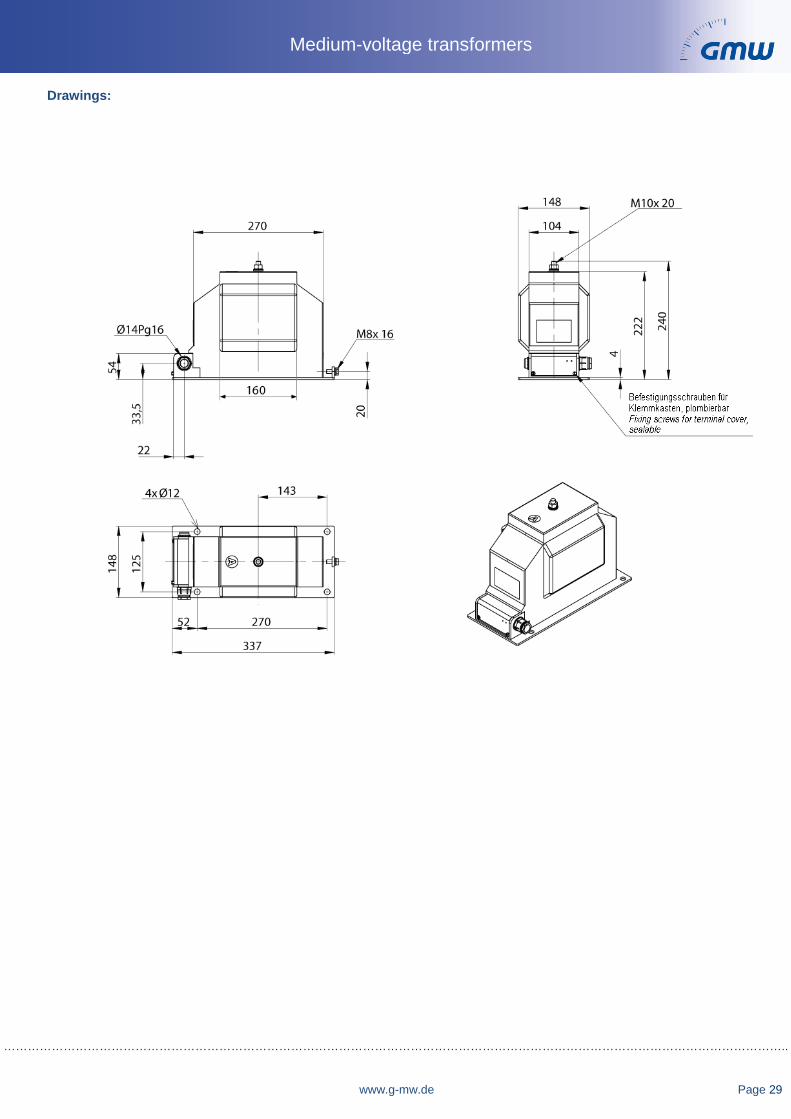
www.g-mw.de Page 29
Medium-voltage transformers
Drawings:

……………………………………………………………………………………………………………………………………………………………………..............
Page 30 www.g-mw.de
Medium-voltage transformers
Double-pole isolated voltage transformer for indoor application 7.2 kV and 12 kV – Narrow type according to DIN 42600, part 9
Description:
Medium-voltage voltage transformers for indoor application, which are converting one or more primary voltages proportional and in-phase into measurable and standardized secondary voltages. These transformers are fully resin-hardened in polyurethane. They can be used for measuring and protection purposes. The medium-voltage voltage transformers are also available with two windings. The maximum quantity of windings depends on the chosen burden and accuracy class. Optionally, the voltage transformers can be produced with secondary tap for two primary rated voltages. Moreover it is possible to have these voltage transformers with two screw-fastened primary fuses (type VTZ12M11-T + F), to protect the surrounding distribution system.
Technical data:
VTZ12M11-T Max. operating voltage Um: 12 kV Power frequency voltage: 28 kV Lightning impulse voltage: 75 kV Rated voltage factor: 1.2 x Un / continuously Primary nominal voltage UPN 3,000 V up to 11,000 V Secondary nominal voltage USN 100 V or 110 V
Nominal burden and accuracy class max. 20VA in cl.0.2 max. 50VA in cl.0.5 max. 100VA in cl.1
Nominal frequency 50 / 60 Hz Insulation class: E Weight: approx. 23 kg
Subject to technical modifications without notice Please note, that the above mentioned data are standard values. Other values on request.

……………………………………………………………………………………………………………………………………………………………………………..
www.g-mw.de Page 31
Medium-voltage transformers
Drawings:

……………………………………………………………………………………………………………………………………………………………………..............
Page 32 www.g-mw.de
Medium-voltage transformers
Single-pole isolated voltage transformer for indoor application 24 kV – Narrow type according to DIN 42600, part 9
Description:
Medium-voltage voltage transformers for indoor application, which are converting one or more primary voltages proportional and in-phase into measurable and standardized secondary voltages. These transformers are fully resin-hardened in polyurethane. They can be used for measuring and protection purposes. The medium-voltage voltage transformers are also available with two windings. The maximum quantity of windings depends on the chosen burden and accuracy class. The single-pole isolated VTs can be equipped additionally with a winding for earth fault detection.
Optionally, the voltage transformers can be produced with secondary tap for two primary rated voltages Moreover it is possible to have these voltage transformers with a screw-fastened primary fuse (type VTS24M32-T + F), to protect the surrounding distribution system.
Technical data:
(E)VTS24M32-TMax. operating voltage Um: 24 kV Power frequency voltage: 50 kV Lightning impulse voltage: 125 kV Rated voltage factor: 1.9 x Un / 8h Primary nominal voltage UPN 13,800/√3 V up to 22,000/√3 V Secondary nominal voltage USN 100/√3 V or 110/√3 V Secondary nominal voltage for winding for earth fault detection (da-dn) 100/3 V or 110/3 V
Nominal burden and accuracy class max. 25VA in cl.0.2 max. 75VA in cl.0.5 max. 150VA in cl.1
Nominal frequency 50 / 60 Hz Insulation class: E Weight: approx. 28 kg
Subject to technical modifications without notice Please note, that the above mentioned data are standard values. Other values on request.

……………………………………………………………………………………………………………………………………………………………………………..
www.g-mw.de Page 33
Medium-voltage transformers
Drawings:

……………………………………………………………………………………………………………………………………………………………………..............
Page 34 www.g-mw.de
Medium-voltage transformers
Double-pole isolated voltage transformer for indoor application 24 kV – Narrow type according to DIN 42600, part 9
Description:
Medium-voltage voltage transformers for indoor application, which are converting one or more primary voltages proportional and in-phase into measurable and standardized secondary voltages. These transformers are fully resin-hardened in polyurethane. They can be used for measuring and protection purposes. The medium-voltage voltage transformers are also available with two windings. The maximum quantity of windings depends on the chosen burden and accuracy class.
Optionally, the voltage transformers can be produced with secondary tap for two primary rated voltages. Moreover it is possible to have these voltage transformers with two screw-fastened primary fuses (type VTZ24M32-T + F), to protect the surrounding distribution system.
Technical data:
VTZ24M32-T Max. operating voltage Um: 24 kV Power frequency voltage: 50 kV Lightning impulse voltage: 125 kV Rated voltage factor: 1.2 x Un / continuously Primary nominal voltage UPN 13,800 V up to 22,000 V Secondary nominal voltage USN 100 V or 110 V
Nominal burden and accuracy class max. 20VA in cl.0.2 max. 50VA in cl.0.5 max. 100VA in cl.1
Nominal frequency 50 / 60 Hz Insulation class: E Weight: approx. 28 kg
Subject to technical modifications without notice Please note, that the above mentioned data are standard values. Other values on request.

……………………………………………………………………………………………………………………………………………………………………………..
www.g-mw.de Page 35
Medium-voltage transformers
Drawings:

……………………………………………………………………………………………………………………………………………………………………..............
Page 36 www.g-mw.de
Medium-voltage transformers
Single-pole isolated voltage transformer for indoor application 36 kV
Description:
Medium-voltage voltage transformers for indoor application, which are converting one or more primary voltages proportional and in-phase into measurable and standardized secondary voltages. These transformers are fully resin-hardened in polyurethane. They can be used for measuring and protection purposes. The medium-voltage voltage transformers are also available with two windings. The maximum quantity of windings depends on the chosen burden and accuracy class. The single-pole isolated VTs can be equipped additionally with a winding for earth fault detection.
Optionally, the voltage transformers can be produced with secondary tap for two primary rated voltages. Moreover it is possible to have these voltage transformers with a screw-fastened primary fuse (type VTS36M44-T + F), to protect the surrounding distribution system.
Technical data:
VTS36M4-T Max. operating voltage Um: 36 kV Power frequency voltage: 70 kV Lightning impulse voltage: 170 kV Rated voltage factor: 1.9 x Un / 8h Primary nominal voltage UPN 24,000/√3 V up to 33,000/√3 V Secondary nominal voltage USN 100/√3 V or 110/√3 V Secondary nominal voltage for winding for earth fault detection (da-dn) 100/3 V or 110/3 V
Nominal burden and accuracy class max. 25VA in cl.0.2 max. 75VA in cl.0.5 max. 150VA in cl.1
Nominal frequency 50 / 60 Hz Insulation class: E Weight: approx. 32 kg
Subject to technical modifications without notice Please note, that the above mentioned data are standard values. Other values on request.

……………………………………………………………………………………………………………………………………………………………………………..
www.g-mw.de Page 37
Medium-voltage transformers
Drawings:

……………………………………………………………………………………………………………………………………………………………………..............
Page 38 www.g-mw.de
Medium-voltage transformers
CTO Split-core current transformer, fully resin-hardened for indoor applications 0.72 kV / 1.2 kV
Features / Benefits - Split-core current transformer suitable for measuring or protection purposes,depending on the design of the CT
- The modular design of this series allows a large number of varieties within thedifferent CT sizes (please see next page for details about the differentdimensions)
- Max. operating voltage: 0.72/3/- kV or 1.2/6/- kV; if the primary conductor issuitably insulated the CT can also be used above 0.72 kV or 1.2 kV
- Primary current range: 50 A … 5000 A- Secondary currents: 1 A, 2 A or 5 A- Rated burden: 2.5 VA … 30 VA- Accuracy classes: 0.2S; 0.2; 0.5S; 0.5; 1; 3- Over-current rated limiting factor for measuring cores: FS5 or FS10- Protection classes: 5P / 10P / PX- Over-current rated limiting factor for protection cores: 5, 10, 15, 20, 30
Dimensions: Primary opening diameter: max. 400 mm Transformer width: 100 - 600 mm Transformer depth: 60 - 300 mm
Please see next page for details about the different dimensions.
General technical specifications: Therm. nominal continuous rated current Icth: 1,0 x IN or 1,2 x IN,
other values upon requestTherm. nominal short-time current Ith: Min. 100 x IN / 1 sec.,
other values upon request Rated dynamic current Idyn: 2,5 x Ith
Max. operating voltage Um: 0,72 kV or 1,2 kV Isolation test voltage: 3 kV, Ueff, 50 Hz, 1 min. or
6 kV, Ueff, 50 Hz, 1 min.
Rated frequency: 50 Hz or 60 Hz, other values upon request Isolation class: E Applicable technical standards: DIN EN 61869, part 1 + 2
(formerly DIN EN 60044-1)
Further information: • Measuring systems fully hardened with Polyurethane resin• The current transformers type CTO are intended for subsequent installation in existing low-voltage switchgear.
In addition, there are customers who use these current transformers in medium-voltage switchgears, if the primary conductor is suitably insulated.Further applications are wind turbines, facilities for power generation on ships, power distribution systems, etc.
• The two parts of the current transformer are held together by four screws with springs or spring clips on the sides, which ensures a permanent contact pressure.
• The secondary connection terminals are factory-fitted with M5 screws. A clear plastic cover serves as an touch protection.
• Protection type: Housing: IP54, Terminal cover: IP20• Operating temperature: -5°C < T < +40°C• Storage temperature: -25°C < T < +70°C• Mounting of CT by means of a baseboard attached to the resin body• Packaging unit: 1 pc.• Customs tariff number: 85043129

……………………………………………………………………………………………………………………………………………………………………………..
www.g-mw.de Page 39
Medium-voltage transformers
Dimension drawings:
* Dimension x + y depends on the type and numberof measuring systems installed..
1) The dimension „y“ for frame size B is 105 mm and for framesize C is 135 mm at type CTO 100 and CTO 120.
Frame size x* y* B1) 90 60 C1) 120 90 D 150 120 E 200 170 F 250 220 G 300 270
Determination of current transformer type:
Example: CTO 200 B 130
Inner diameter (d1: 130 mm)
Frame size (B: 90 mm)
CT type: CTO 200
CT type b1 b2 b3 max. d1 d2 h1 h2 h3 max. frame size Deliverable CTO 100 100 100 60 50 6 120 60 3 B - C yes CTO 120 120 120 70 65 6 135 67,5 3 B - C yes CTO 135 135 150 120 90 9 150 75 10 B - C yes CTO 150 150 150 120 110 9 170 85 10 B - C yes CTO 170 170 170 150 110 11 185 92,5 10 B - C yes CTO 200 200 200 180 140 11 200 100 10 B - G yes CTO 250 250 250 230 160 11 290 145 10 B - G yes CTO 300 300 300 280 210 11 340 170 10 B - G yes CTO 350 350 350 330 270 11 390 195 10 B - G yes CTO 500 500 500 440 400 11 500 250 10 B - G yes CTO 600 600 600 500 400 11 640 320 10 B - G yes
……………………………………………………………………………………………………………………………………………………………………..............
Page 40 www.g-mw.de
Medium-voltage transformers
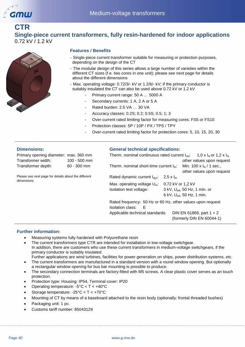
CTR Single-piece current transformers, fully resin-hardened for indoor applications 0.72 kV / 1.2 kV
Features / Benefits - Single-piece current transformer suitable for measuring or protection purposes,depending on the design of the CT
- The modular design of this series allows a large number of varieties within thedifferent CT sizes (f.e. two cores in one unit); please see next page for detailsabout the different dimensions
- Max. operating voltage: 0.72/3/- kV or 1.2/6/- kV; if the primary conductor issuitably insulated the CT can also be used above 0.72 kV or 1.2 kV
- Primary current range: 50 A … 5000 A- Secondary currents: 1 A, 2 A or 5 A- Rated burden: 2.5 VA … 30 VA- Accuracy classes: 0.2S; 0.2; 0.5S; 0.5; 1; 3- Over-current rated limiting factor for measuring cores: FS5 or FS10- Protection classes: 5P / 10P / PX / TPS / TPY- Over-current rated limiting factor for protection cores: 5, 10, 15, 20, 30
Dimensions: Primary opening diameter: max. 360 mm Transformer width: 100 - 500 mm Transformer depth: 60 - 300 mm
Please see next page for details about the different dimensions.
General technical specifications: Therm. nominal continuous rated current Icth: 1,0 x IN or 1,2 x IN,
other values upon requestTherm. nominal short-time current Ith: Min. 100 x IN / 1 sec.,
other values upon request Rated dynamic current Idyn: 2,5 x Ith
Max. operating voltage Um: 0,72 kV or 1,2 kV Isolation test voltage: 3 kV, Ueff, 50 Hz, 1 min. or
6 kV, Ueff, 50 Hz, 1 min.
Rated frequency: 50 Hz or 60 Hz, other values upon request Isolation class: E Applicable technical standards: DIN EN 61869, part 1 + 2
(formerly DIN EN 60044-1)
Further information: • Measuring systems fully hardened with Polyurethane resin• The current transformers type CTR are intended for installation in low-voltage switchgear.
In addition, there are customers who use these current transformers in medium-voltage switchgears, if theprimary conductor is suitably insulated.Further applications are wind turbines, facilities for power generation on ships, power distribution systems, etc.
• The current transformers are manufactured in a standard version with a round window opening. But optionallya rectangular window opening for bus bar mounting is possible to produce.
• The secondary connection terminals are factory-fitted with M5 screws. A clear plastic cover serves as an touchprotection.
• Protection type: Housing: IP54, Terminal cover: IP20• Operating temperature: -5°C < T < +40°C• Storage temperature: -25°C < T < +70°C• Mounting of CT by means of a baseboard attached to the resin body (optionally: frontal threaded bushes)• Packaging unit: 1 pc.• Customs tariff number: 85043129

……………………………………………………………………………………………………………………………………………………………………………..
www.g-mw.de Page 41
Medium-voltage transformers
Dimension drawings:
* Dimension x + y depends on the type and numberof measuring systems installed.
1) The dimension „y“ for frame size A is 75 mm, size B it’s105 mm and size C it’s 135 mm at type CTR 100; CTR 110and CTR 120.
Frame size x* y* A1) 60 30 B1) 90 60 C1) 120 90 D 150 120 E 200 170 F 250 220 G 300 270
Determination of current transformer type:
Example: CTR 200 B 130
Inner diameter (d1: 130 mm)
Frame size (B: 90 mm)
CT type: CTR 200
CT type b1 b2 b3 max. d1 d2 h1 h2 h3 max. frame size Deliverable CTR 100 100 100 80 60 9 110 55 5 C yes CTR 110 110 110 90 70 9 120 60 5 C yes CTR 120 120 120 100 75 9 130 65 5 C on demand CTR 135 135 150 130 90 9 150 75 10 C yes CTR 150 150 150 130 110 9 165 82,5 10 D yes CTR 170 170 170 150 110 11 185 97,5 10 D yes CTR 200 200 200 180 140 11 220 110 10 E yes CTR 250 250 250 230 150 11 270 135 10 E yes CTR 300 300 300 280 210 11 330 165 10 F yes CTR 350 350 350 330 250 11 380 190 10 F on demand CTR 400 400 400 370 300 13 430 215 15 G on demand CTR 500 500 500 440 360 13 530 265 15 G yes

……………………………………………………………………………………………………………………………………………………………………..............
Page 42 www.g-mw.de
Medium-voltage transformers
ASG 106 Tube current transformer, fully resin-hardened for indoor applications 0.72 kV
Features / Benefits - Tube current transformer with up to 4 measuring systems
integrated in one housing- Combination of measuring and protection transformers in
one housing is possible- Max. operating voltage: 0.72/3/- kV; if the primary conductor is
suitably insulated the CT can also be used above 0.72 kV- Primary current range: 40 A … 1250 A- Secondary currents: 1 A, 2 A or 5A- Rated burden: 2.5 VA … 30 VA- Accuracy classes: 0.2S; 0.2; 0.5S; 0.5; 1; 3- Over-current rated limiting factor for measuring cores: FS5 or FS10- Protection classes: 5P / 10P / PX- Over-current rated limiting factor for protection cores: 5, 10, 15, 20, 30
Dimensions:
Primary opening diameter: 106 mm Transformer width: 190 mm Transformer depth: 50, 100, 170, 214 mm*
Please see next page for details about the different dimensions.
General technical specifications:
Therm. nominal continuous rated current Icth: 1.2 x IN,
other values upon requestTherm. nominal short-time current Ith: 25 kA / 3 sec.,
other values upon request Rated dynamic current Idyn: 2.5 x Ith
Max. operating voltage Um: 0.72 kV Isolation test voltage: 3 kV, Ueff, 50 Hz, 1 min.
Rated frequency: 50 Hz, other values upon request Isolation class: F Applicable technical standards: DIN EN 61869, part 1 + 2
(formerly DIN EN 60044-1)
Further Information: • Measuring systems fully hardened with Polyurethane resin• Full resin hardening and the used high-quality materials allow the application under extreme mechanical
and climatic conditions (f.e. application close to generator)• Resin material with high fire safety (UL94-V0)• Current transformer type tested by Siemens AG• The current transformers type ASG 106 are intended for installation in low-voltage switchgear.
In addition, there are customers who use these current transformers in medium-voltage switchgears, if theprimary conductor is suitably insulated.Further applications are wind turbines, facilities for power generation on ships, power distribution systems…
• Measuring cores with PTB approval available• 4 different housing depths allow the realisation of different customer requirements• Reduction of external wiring by means of flexible secondary connection cables (3.6 m, 4 mm², other
lengths and profiles upon request)• Flexible terminal connections are protected by additional textile braided sleeving.• Influence of cable length is taken into account in the interpretation of the measurement systems• Operating temperature: -5°C < T < +60°C• Storage temperature: -25°C < T < +70°C• Housing material: ABS, self-extinguishing, UL94-V0• Mounting of current transformers by with 2 pieces (optional 4 pieces) hexagon bolts M8x30• Packaging unit: 1 pc.• Customs tariff number: 85043129

……………………………………………………………………………………………………………………………………………………………………………..
www.g-mw.de Page 43
Medium-voltage transformers
*Dimension x + y depends on the type and numberof measuring systems installed.
Measurements:
Housing depth x* 50 mm 100 mm 170 mm 214 mm
Measurement y (optional!)
- 85 mm 155 mm 199 mm

……………………………………………………………………………………………………………………………………………………………………..............
Page 44 www.g-mw.de
Medium-voltage transformers

……………………………………………………………………………………………………………………………………………………………………………..
www.g-mw.de Page 45
Medium-voltage transformers
CHECKLIST
Required informations for enquiries or purchase orders of Medium-Voltage Current Transformers
Primary rated current (for each core) e.g. 100 A
Secondary rated current (for each core) e.g. 5 A
Core 1: rated power + accuracy class e.g. 5VA Kl. 0,2 S
Core 2: (if existing) rated power + accuracy class e.g. 5VA Kl. 0,5
Core 3: (if existing) rated power + accuracy class e.g. 10VA Kl. 5P10
Rated frequency e.g. 50 Hz
Therm. rated uninterrupted current Icth e.g. 1,2 x IN oder 120 %
Therm. rated short-time current / period Ith e.g. 20 kA / 1 Sek.
Rated insulation level e.g. 12/28/75 kV
Please note, the dimensions of primary wire or the requested inner diameter is required for winding type- and split-core current transformers (Type CTR + CTO). (Not required for support type current transformers, type CTS!)
Required informations for enquiries or purchase orders of Medium-Voltage Voltage Transformers
Primary rated voltage e.g. 10.000/√3 V
Secondary rated voltage (for each winding) e.g. 100/√3
Winding 1: rated power + accuracy class e.g. 15VA Kl. 0,2
Winding 2: (if existing) rated power + accuracy class e.g. 15VA Kl. 0,5
Winding 3: (if existing) rated power + accuracy class e.g. 30VA Kl. 3P (da-dn)
Rated frequency e.g. 50 Hz
Rated voltage factor e.g. 1,9 x UN / 8h
Rated insulation level e.g. 12/28/75 kV
Above-mentioned definitions according DIN/EN/IEC 61869-1/2/3

……………………………………………………………………………………………………………………………………………………………………..............
Page 44 www.g-mw.de
Medium-voltage transformers

……………………………………………………………………………………………………………………………………………………………………………..
www.g-mw.de Page 47
Medium-voltage transformers

Gilgen, Müller & Weigert (GMW) GmbH & Co. KGAm Farrnbach 4A90556 Cadolzburg
Tel: +49 (0) 9103 7129-0Fax: +49 (0) 9103 7129-205/207E-Mail: [email protected]: www.g-mw.de
Manager: Prof. Dr. h.c. Wolfgang Gilgen
TAX: DE815535316
For further information of GMW, we would like to recommend you to visit our website:
www.g-mw.de
Stan
d: 2
016-
08R
eser
ve te
chni
cal c
hang
es27
867
0009
0
The data contained in the product catalog are to the best of my knowledge and belief. Changes and errors are reserved. similar pictures provide any terms within the meaning of § represents 305 I BGB. There are notes without independent regulatory con-tent that bring only expressed that the information contained in the catalog so far are preliminary and non-binding, as before or at the conclusion of a contract yet can be corrected. A contractual arrangements content, in particular a possible restriction of the rights of the contracting party in liability-or warranty legal terms, these instructions can not be removed.