
Power Pro - Welcome to the NCE Information Station · voltage to your Power Pro or PB105 is 18...
93
1 Power Pro Power Pro System Reference Manual System Reference Manual
-
Upload
duongtuyen -
Category
Documents
-
view
213 -
download
0
Transcript of Power Pro - Welcome to the NCE Information Station · voltage to your Power Pro or PB105 is 18...

1
Power ProPower ProSystem Reference
ManualSystem Reference
Manual

2
��������
����
�����������
������
����
��������������������� �������
��������������� �
!�
��� ������
Basic Set Up of 5 AmpBasic Set Up of 5 AmpBasic Set Up of 5 AmpBasic Set Up of 5 AmpBasic Set Up of 5 AmpPower Pro SystemPower Pro SystemPower Pro SystemPower Pro SystemPower Pro System
BE CAREFULBE CAREFULBE CAREFULBE CAREFULBE CAREFULAn NCE P515 power supply (15VAC - 5AMP) is the preferred transformer for your system. Ifyou are using a different transformer be sure to measure the actual no load voltage beforeconnecting it to your system. Many 16 Volt transformers put out 19 to 20 Volts with no load. Ifyou have a transformer that puts out more than 18 Volts do not use it. The maximum inputvoltage to your Power Pro or PB105 is 18 Volts AC. Voltages higher than 18 Volts AC willultimately destroy your booster resulting in an expensive repair charge.

3
Quick StartQuick StartQuick StartQuick StartQuick StartContents of the 5 Amp Power Pro System:Contents of the 5 Amp Power Pro System:Contents of the 5 Amp Power Pro System:Contents of the 5 Amp Power Pro System:Contents of the 5 Amp Power Pro System:
Power Pro System BoxPro CabSeven foot coiled cableTwelve inch flat cableUTP cab bus panelPower Pro system reference manual
We recommend that you follow the instructions below to connect your systemto a small test track first. After your system is checked out completely andknown to be working then consider the final installation locations forcomponents and connections to the track.
TRYING OUT YOUR POWER PRO:TRYING OUT YOUR POWER PRO:TRYING OUT YOUR POWER PRO:TRYING OUT YOUR POWER PRO:TRYING OUT YOUR POWER PRO:
#1 Disconnect the existing power supplies from your layout.
#2 Connect the long (7 foot) coiled cable from the cab into the Power Pro CAB BUSsocket.
#3 Plug one end of the short (1 foot) cable into the Power Pro CONTROL BUSsocket that is next to the CAB BUS socket. The other end of this wire plugs intoeither one of the remaining CONTROL BUS sockets. This connects the“Command Station” portion of the Power Pro to the “Power Booster” portion.
#4 Connect your power source to the terminals marked POWER. Your power sourcemust have a voltage output within the range of 12-18 volts AC or 18-28 voltsDC. Do not exceed these voltages as damage to the Power Pro is certain toresult. If there is not enough voltage (under about 12VDC) the left handSTATUS light on the Power Pro will flash quickly. There will be a similarindication if the DCC signal from the command station is lost . The Power Pro isfactory adjusted to put out the NMRA recommended 14.25 volts for N, HO andS scales.
Connect the transformer to both sets of power terminals on the Power Pro asshown (do not plug it in to the wall yet).
#5 Set up a test track. Obtain a length or two of flex track, or better yet, use that oldcircle of Atlas Snap Track you’ve had kicking around for years. Do NOTconnect the Power Pro up to your layout at this time. We want you to test theoperation of your new DCC system without the complication of troubleshootingany layout wiring, closed gaps, broken switch points, etc. Once you areconfident that your new Power Pro DCC system is up and running as advertisedthen hook it up to the layout (after finishing the Quick Start Guide). Make surethat your layout wiring can stand a continuous 5 Amps of current. Werecommend a minimum of #16 feeder bus, preferably #14 and at least #22 AWGpower drops from the rails to the feeder bus.
If you have a locomotive with a DCC decoder already installed connect two

4
wires from your test track to the TRACK terminals of the Power Pro.#6 Carefully inspect all wiring to make sure proper connections have been
made. Do not permit unused decoder wires to touch each other. A piece oftape will help here.
#7 Plug in the power source and/or turn on the power.#8 The display of the cab should look something like:
LOC: 003 00:03AMLOC: 003 00:03AMLOC: 003 00:03AMLOC: 003 00:03AMLOC: 003 00:03AM
FWD: 000 -------FWD: 000 -------FWD: 000 -------FWD: 000 -------FWD: 000 -------
This is what we call the ‘NORMAL DISPLAY’. The fast clock in the upperright hand corner will most likely show a different time.The following cab buttons must be pressed in the proper sequence toacquire control of the locomotive #3 (in the above example locomotive #3 isalready selected):a. Press SELECT LOCO button once.b. Press the “3” button once. DO NOT press 0 then 3.c. Press ENTER.Note: By convention, all locomotive decoders have their short address setto 3 at the factory.
TIP #1 If you make a mistake while entering numbers on the cab just keeppressing more numbers until the number entry field clears, then enter thecorrect numbers.
TIP #2 Whenever the cab is waiting for you to enter data (a flashing blacksquare is on the screen at the point where the numbers will go) you canpress the PROG/ESC key to “escape” what you were doing and return tonormal operation mode.
TIP #3 Whenever you have pressed a button (such as SELECT LOCO) andyou want to keep what ever number that is already on the screen just pressENTER.
#9 To operate the locomotive, the following controls are used:a. The thumbwheel will increase/decrease speed. The speed controlbuttons that flank the thumbwheel on either side may also be used asdesired to control the loco speed.b. Pressing the DIRECTION button will cause the loco direction to reverse.CONGRATULATIONS! You are now operating one locomotive with DCCcontrol. In most cases, less than twenty minutes has elapsed since youstarted reading this Quick Start Guide.
After completing your Quick Start, go to Page 9 - “Completingthe Quick Start.”

5
�������������
��������� �����
��� ������
���� �
���������� �
���������������������������� ��
�����!�����"#$��%�&
����'����������������������� ������������ ���������� ��������(!��)��� ��� �*+$������ ������� � ��*+��&�����+ ���
Basic Set Up of 10 AmpBasic Set Up of 10 AmpBasic Set Up of 10 AmpBasic Set Up of 10 AmpBasic Set Up of 10 AmpPower Pro SystemPower Pro SystemPower Pro SystemPower Pro SystemPower Pro System

6
Basic Set Up of 10 AmpBasic Set Up of 10 AmpBasic Set Up of 10 AmpBasic Set Up of 10 AmpBasic Set Up of 10 AmpPower Pro SystemPower Pro SystemPower Pro SystemPower Pro SystemPower Pro System
BE CAREFULBE CAREFULBE CAREFULBE CAREFULBE CAREFULThe maximum input voltage to your PH-10 or PH-10R is 22 Volts AC. Voltages higher than 22Volts AC will ultimately destroy your booster resulting in an expensive repair charge.
We recommend the Hammond Manufacturing 18V AC, 10 Amp transformer. This is available atDigikey and their part number is HM538. If you are using a different transformer be sure tomeasure the actual no load voltage before connecting it to your system.
Quick StartQuick StartQuick StartQuick StartQuick StartContents of the 10 Amp PH-10 System:Contents of the 10 Amp PH-10 System:Contents of the 10 Amp PH-10 System:Contents of the 10 Amp PH-10 System:Contents of the 10 Amp PH-10 System:
CS02 Command StationPB110A BoosterPro CabSeven foot coiled cableTwelve inch, four wire flat cableSeven foot, four wire flat cableUTP cab bus panelSeven foot, six wire flat cable for the UTP panelPower Pro system reference manual
We recommend that you follow the instructions below to connect your systemto a small test track first. After your system is checked out completely andknown to be working then consider the final installation locations forcomponents and connections to the track.
TRYING OUT YOUR PH-10:TRYING OUT YOUR PH-10:TRYING OUT YOUR PH-10:TRYING OUT YOUR PH-10:TRYING OUT YOUR PH-10:
#1 Disconnect the existing power supplies from your layout.
#2 Connect one end of the long (7 foot) coiled cable from the cab into the CS02CAB BUS socket. Plug the other end in the ProCab.
#3 We supply a twelve inch and a seven foot four wire, flat cable for the CONTROLBUS. Depending on where you mount the CS02 and the PB110A, use either theshort or long cable. Plug one end of the cable into the CS02 CONTROL BUSsocket. The other end of this cable plugs into one of the CONTROL BUSsockets of the PB110A. This connects the “Command Station” portion of thePower Pro to the “Power Booster” portion.
#4 Connect your power source to the terminals marked POWER. Your power sourcemust have a voltage within the range of 16-22 volts AC. Follow the diagram tothe left. Make special note of the differences between the CS02 power and thePB110A power wiring. Do not exceed these voltages as damage to the PB110A is

7
STATUS light on the PB110A will flash quickly. There will be a similar indication ifthe DCC signal from the command station is lost . The PB110A is factoryadjusted to put out the NMRA recommended 16 volts for O and Large Scale.
Connect the transformer to power terminals on the CS02 and the PB110A asshown (do not plug it in to the wall yet).
NOTE: Hook up to the PB110A and the CS02 are different.
#5 Set up a test track. Obtain a length or two of flex track, or better yet, use that oldcircle of Atlas Snap Track you’ve had kicking around for years. Do NOTconnect the PH-10 up to your layout at this time. We want you to test theoperation of your new DCC system without the complication of troubleshootingany layout wiring, closed gaps, broken switch points, etc. Once you areconfident that your new PH -10 DCC system is up and running then hook it upto the layout (after finishing the Quick Start Guide). Make sure that your layoutwiring can stand a continuous 10 Amps of current. We recommend a minimum of#14 feeder bus, preferably #12 and at least #18 AWG power drops from the railsto the feeder bus.
Connect two wires from your test track to the TRACK terminals of the PH-10.#6 Carefully inspect all wiring to make sure proper connections have been made.#7 Plug in the power source and/or turn on the power.#8 The display of the cab should look something like:
LOC: 003 00:03AMLOC: 003 00:03AMLOC: 003 00:03AMLOC: 003 00:03AMLOC: 003 00:03AM
FWD: 000 -------FWD: 000 -------FWD: 000 -------FWD: 000 -------FWD: 000 -------
This is what we call the ‘NORMAL DISPLAY’. The fast clock in the upper righthand corner will most likely show a different time.The following cab buttons must be pressed in the proper sequence to acquirecontrol of locomotive #3 (in the above example locomotive #3 is alreadyselected):a. Press SELECT LOCO button once.b. Press the “3” button once. DO NOT press 0 then 3.c. Press ENTER.

8
Note: By convention, all locomotive decoders have their short address set to 3at the factory.
TIP #1 If you make a mistake while entering numbers on the cab just keeppressing more numbers until the number entry field clears, then enter the correctnumbers.
TIP #2 Whenever the cab is waiting for you to enter data (a flashing black squareis on the screen at the point where the numbers will go) you can press thePROG/ESC key to “escape” what you were doing and return to normaloperation mode.
TIP #3 Whenever you have pressed a button (such as SELECT LOCO) and youwant to keep what ever number that is already on the screen just press ENTER.
#9 To operate the locomotive, the following controls are used:a. The thumbwheel will increase/decrease speed. The speed control buttonsthat flank the thumbwheel on either side may also be used as desired to controlthe loco speed.b. Pressing the DIRECTION button will cause the loco direction to reverse.CONGRATULATIONS! You are now operating one locomotive with DCCcontrol. In most cases, less than twenty minutes has elapsed since you startedreading this Quick Start Guide.
After completing your Quick Start, go to Page 9 - “Completing theQuick Start.”

9
COMPLETING THE QUICK STARTOperating one locomotive is fun — for awhile. But operating two or three locomotives is a lotmore fun for a much longer time. Advancing beyond this simple DCC testing requires decoderinstallation into more locomotives and perhaps a few straight pieces added to your circle oftrack. After you have at least two locomotives with decoders we can continue with twolocomotives simultaneously operating under DCC control. To accomplish this, both decodersneed to be installed in their respective locomotives and at least one decoder will need to beprogrammed with a different address.
PROGRAMMING A LOCOMOTIVE ADDRESS#1 The first item of business in this section is to connect a programming track. We simply use
an old piece of snap track connected to the PROGRAMMING TRACK terminals of thesystem box.
#2 Place a locomotive with an installed decoder on the programming track.
#3 Press the PROG button four times to get to the programming track menu.
Your cab should read:
SELMODE xx:xxPMSELMODE xx:xxPMSELMODE xx:xxPMSELMODE xx:xxPMSELMODE xx:xxPM
USE PROGRAM TRKUSE PROGRAM TRKUSE PROGRAM TRKUSE PROGRAM TRKUSE PROGRAM TRK
xx:xx represents the fast clock which may display any time at this point.
#4 Press ENTER to use the programming track and you will see:
PROG TRK xx:xxPMPROG TRK xx:xxPMPROG TRK xx:xxPMPROG TRK xx:xxPMPROG TRK xx:xxPM
1=STD 2=CV 3=REG1=STD 2=CV 3=REG1=STD 2=CV 3=REG1=STD 2=CV 3=REG1=STD 2=CV 3=REG
NOTE: The STATUS light of the booster will flash rapidly indicating that the power boosterportion of the system has turned off track power. This is due to a loss of DCC signal from thecommand station half of the Power Pro and is normal when using the programming track.
#5 Press “1” to use Standard programming. You will see:
MAIN OFF xx:xxPMMAIN OFF xx:xxPMMAIN OFF xx:xxPMMAIN OFF xx:xxPMMAIN OFF xx:xxPM
MANUFACTURER:___MANUFACTURER:___MANUFACTURER:___MANUFACTURER:___MANUFACTURER:___
After a moment the blank space after MANUFACTURER: will be filled in with “011” which isthe NMRA code for NCE Corporation. All manufacturers have different codes.
If you get a CAN NOT READ CV message the decoder is not responding. Check the locomotive,decoder and programming track wiring. An older decoder that uses “paged” mode (discussed later)can take up to 15 seconds to read the values.
#6 Press ENTER read the version of the decoder version (this will vary depending upon whichmodel decoders were shipped with your system).
#7 Press ENTER again to see:
ACTIVE ADR:SHORTACTIVE ADR:SHORTACTIVE ADR:SHORTACTIVE ADR:SHORTACTIVE ADR:SHORT
SETUP ADR 1=YESSETUP ADR 1=YESSETUP ADR 1=YESSETUP ADR 1=YESSETUP ADR 1=YES

10
By convention all DCC locomotive decoders are set to short address #3 at the factory. If yourdecoder has not had its address changed you will see a short address as the active address. Press 1to set up the address.
ACTIVE ADR:SHORTACTIVE ADR:SHORTACTIVE ADR:SHORTACTIVE ADR:SHORTACTIVE ADR:SHORT
SHORT ADR: 003SHORT ADR: 003SHORT ADR: 003SHORT ADR: 003SHORT ADR: 003
TIP A decoder can have 2 different addresses, the Short Address (values from 1-127) or the LongAddress (sometimes called 4 digit with a range of 0000-9999). A decoder can use one or theother but not both at the same time. Some entry level decoders such as MRC can only use theShort Address.
#8 Press ENTER to keep the current short address set to 3.
#9 Press ENTER to skip activating the short address.
#10 Next you will see the Long Address (which is probably set to 0000 or sometimes to 9999).With older decoders, it may take a up to 30 seconds to read the long address.
This one we will change.
#11 You will likely want to enter the number on the side of the locomotive cab as the LongAddress. Type in the number of the locomotive and press ENTER.
#12 Press 1 to activate the Long Address.
You have just changed the Long Address.
At this point, press PROG/ESC twice to exit the program track mode.
You have just completed the hardest part of DCC… programming the locomotive on theprogramming track.
By now the left status light of the booster will be glowing steadily indicating that track powerhas been restored. Put your freshly programmed locomotive back on the test track, it won’t runon the programming track.
To select the locomotive:
a. Press SELECT LOCO buttonb. Press the digits corresponding to the Long Address you just programmed..c. Press ENTER
At this point you should have control of the locomotive. Now is the time to program up asecond locomotive and run them both.
RUNNING TWO LOCOMOTIVES WITH ONE CAB
#1 Select the first locomotive you wish to run (SELECT LOCO followed by address thenENTER).
#2 Press RECALL to store this locomotive in one of the internal recall “slots” of the cab. Thedisplay of the cab will now show a locomotive of 000.
#3 Select the second locomotive and start running it.
#4 By pressing RECALL you can toggle back and forth between the two different locomotives.At any time you can select a new locomotive “over the top” of any locomotive already onthe display. The existing locomotive will be forgotten by the cab with the new one taking it’splace. The one in RECALL will remain available for recall.

11
Copyright 1994 - 2005
NCE Corporation899 Ridge Road
Webster, NY 14580(585) 671-0370
Power Pro~ The Finest in Digital Command Control ~
SystemReference Manual
for Power Pro 5 Amp Systems
and
PH-10 10 Amp Systems

12
CUSTOMER SERVICECustomer Service is handled through our factory warranty center or by your dealer. It isfaster to deal direct with the factory. Please write or call us before returning any products toour warranty center. Sometimes the problem is easily solved over the phone. If writing makesure you include your name, address and phone number and the times that you can bereached at that number. This will greatly expedite our service to you if you have questions.
NCE Warranty Center899 Ridge RoadWebster, NY 14580
Phone: (585) 671-0370Fax: (585) 671-9337
Email Address: [email protected] Site: www.ncedcc.com
We reserve the right to either repair or replace components sent to us for in-warranty service.The warranty period will begin on the date shown on your retail sales receipt.Please do not send anything for repair without first writing or calling to explain the problem.Also remember include your name, address and phone number with a brief description of theproblem.
REGISTER MY SYSTEM… WHY?By registering your Power Pro DCC system with us you will receive personal notification ofany software and hardware updates. At various times we provide free updates to ourcustomers. At other times there is a nominal charge to cover shipping and handling (usuallyabout $5). We do NOT use your name or address for any purpose other than upgradenotification. We will not sell or otherwise provide your personal information to any otherperson, company or entity.
ABOUT THIS MANUALThis manual covers the installation and operation of the NCE Power Pro 5 Amp and 10 AmpDCC systems. It is not a comprehensive tutorial on all the aspects of Digital CommandControl. It is not necessary to know the inner workings of DCC to use this system. Someusers may wish to delve deeper into the how and why of Digital Command Control formodel railroads, especially those wishing to use the computer interface of the Power Pro. Forthose interested in the “nuts and bolts” we recommend the reading of the following NMRAStandards and recommended Practices as they pertain to DCC. Applicable standards are: S-9,S9.1 and S-9.2 and Recommend Practices: RP-9.1.1 through RP-9.2.4. These documents areavailable via the Internet at www.nmra.org.
The NCE Publications Department wrote this manual. Please address comments regardingthe manual to:
NCE Publications Dept.899 Ridge RoadWebster, NY [email protected]

13
TABLE OF CONTENTSCOMPLETING THE QUICK START ................................................................................... 9PROGRAMMING A LOCOMOTIVE ADDRESS .................................................................. 9RUNNING TWO LOCOMOTIVES WITH ONE CAB ..................................................... 10CUSTOMER SERVICE .......................................................................................................... 12REGISTER MY SYSTEM… WHY? .................................................................................... 12INSTALLING DECODERS ................................................................................................... 15PRECAUTIONARY NOTES FOR DECODERS ................................................................ 16GENERAL SYSTEM INSTALLATION .............................................................................. 17DEVICE LOCATIONS ........................................................................................................... 17
PROGRAMMING TRACK ............................................................................................. 17REVERSE BLOCKS, WYES, AND CROSSOVERS ...................................................... 18WIRING ............................................................................................................................ 18
SYSTEM EQUIPMENT DESCRIPTIONS ......................................................................... 19THE POWER PROTM SYSTEM UNIT ................................................................................ 19POWER PROTM PH-10 SYSTEM UNIT ............................................................................ 19THE COMMAND STATION ............................................................................................... 20
COMMAND STATION CONNECTIONS AND INDICATORS ............................... 20COMPUTER INTERFACE PORT ................................................................................ 20CONTROL BUS SOCKETS ............................................................................................ 20STATUS LIGHT ............................................................................................................... 20SYSTEM SPECIFICATIONS .......................................................................................... 20
REPLACING THE EPROM IN YOUR POWER PRO: .................................................... 21BATTERY CONNECT JUMPER ......................................................................................... 21POWER BOOSTER ............................................................................................................. 22
CONNECTIONS, CONTROLS AND INDICATORS .................................................. 22TRACK VOLTAGE ADJUSTMENT - PB105 ............................................................. 23TRACK VOLTAGE ADJUSTMENT - PB110A ......................................................... 24USING MULTIPLE BOOSTERS ON YOUR LAYOUT ............................................ 24
DOUBLE GAPPED LAYOUTS ................................................................................ 24COMMON RAIL LAYOUTS ..................................................................................... 24
CONNECTION TO AUTOMATIC REVERSING MODULES ........................................ 24THE PROCAB ....................................................................................................................... 25
THE LCD SCREEN ......................................................................................................... 26LOCOMOTIVE CONTROL AREA ............................................................................... 26COMMONLY USED BUTTONS ................................................................................... 27LOCO AND ACCESSORY SELECTION GROUP ....................................................... 28DATA ENTRY/FUNCTION CONTROL ...................................................................... 28CONSIST SETUP GROUP ............................................................................................. 28PROGRAMMING AND EXTENDED FUNCTION CONTROL .............................. 29CAB SETUP ..................................................................................................................... 30CAB BUTTON NUMBERING SCHEME ..................................................................... 32TABLE OF FACTORY DEFAULT VALUES ............................................................... 336 WIRE CAB BUS CABLE WITH RJ-12 CONNECTORS ....................................... 33
OPERATING PROCEDURES ............................................................................................... 34THE “NORMAL” DISPLAY ......................................................................................... 34SELECTING A LOCOMOTIVE OR CONSIST ........................................................... 34CONTROLLING HEADLIGHTS AND OTHER DECODER FUNCTIONS ........... 35
CONSISTS - OLD AND ADVANCED CONSISTS EXPLAINED .................................... 36ADVANCED CONSISTS ................................................................................................. 36OLD STYLE CONSISTS (ALSO CALLED BRUTE FORCE OR UNIVERSAL) ... 36
SETTING UP AN ADVANCED CONSIST ......................................................................... 36DROPPING A LOCOMOTIVE FROM AN ADVANCED CONSIST ........................ 38ADDING A LOCO TO AN ADVANCED CONSIST .................................................... 38CLEARING AN ADVANCED CONSIST ...................................................................... 39CHANGING THE LEAD LOCO .................................................................................... 39

14
OLD STYLE CONSISTS ....................................................................................................... 40SETUP AN OLD STYLE CONSIST ............................................................................. 40ADDING A LOCO TO AN OLD STYLE CONSIST ................................................... 40DROPPING A LOCO FROM AN OLD STYLE CONSIST ........................................ 41CLEARING AN OLD STYLE CONSIST ...................................................................... 42
CONTROLLING TURNOUTS AND OTHER ACCESSORIES ........................................ 43MOMENTUM BUTTON ...................................................................................................... 44USE MACROS TO CONTROL TURNOUTS ..................................................................... 45
MACROS EXPLAINED ................................................................................................. 45PROGRAMMING PROCEDURES .................................................................................. 46
ACCESSING PROGRAMMING MODES ...................................................................... 46PROGRAMMING MENUS TABLE OF CONTENTS ................................................... 47PROGRAMMING ON THE MAIN ...................................................................................... 49ASSIGNING A LOCO TO A CAB ......................................................................................... 56SET THE SYSTEM CLOCK ................................................................................................. 57USE PROGRAM TRACK ...................................................................................................... 58SETUP COMMAND STATION ........................................................................................... 67SETTING THE CAB PARAMETERS ................................................................................. 73PROGRAM ACCESSORY DECODERS ON THE MAIN .................................................. 75PROGRAM MACROS ............................................................................................................ 76BROWSE CONSISTS ............................................................................................................. 78PROGRAM SIGNAL DECODERS ........................................................................................ 79RS232 SERIAL COMPUTER INTERFACE ....................................................................... 80CABLE ............................................................................................................................... 80BINARY COMMAND SET (RECOMMENDED) .............................................................. 80HELPFUL HINTS .................................................................................................................. 84TROUBLE SHOOTING ......................................................................................................... 85COPYRIGHTS ......................................................................................................................... 86WARRANTY ........................................................................................................................... 86FCC STATEMENT ................................................................................................................. 87ABOUT NCE ........................................................................................................................... 87ADVANCED LAYOUT WIRING ......................................................................................... 88MENU NAVIGATION CHART ............................................................................................ 90

15
INSTALLING DECODERSRead the following section on decoders before starting. There are shortcuts to temporaryinstallation of the other components, but do not shortcut the decoder. We recommend you getyour first decoder installed by a dealer or locomotive manufacturer just so you have a goodexample of how it’s done.
The most important part of a successful decoder installation is proper isolation of both motorbrushes from the track so that they are driven only by the decoder. Failure to isolate willdefinitely damage the decoder. Damage caused by failure to isolate the motor is not be coveredby the guarantee.
We find it preferable to mount the decoder with 1/2" wide 3M photo-mount double sided foamtape (we get ours at the local supermarket).
Before test running your newly converted locomotive on full power double check your wiring tomake sure the motor is fully isolated and that there are no pinched or broken wires. We seemany decoders returned due to wires getting pinched between the body shell and frame causingshorts.
Due to the high in-rush current of incandescent grain-of-wheat type bulbs (about 10 times thenormal operating current) we have rated the decoder function outputs at 100mA each. Werecommend Miniatronics part number 18-014-10 (2.4mm diameter 14 volt/30mA) bulbs forgood results. If you are running higher voltages you will need to use 16 or 18 volt bulbs.
If you need to use higher current lamps (50-150mA) we recommend a 22 ohm 1/4 Watt resistorin series with each bulb (this will also greatly extend bulb life). The function outputs are rated at150mA continuous if used with LEDs or other low in-rush devices.Always make sure the motor is isolated from the frame. Always make sure metal couplers areisolated from the frame.
,���'���!�� ��� ���-.*��)���/�����&����0�*�� &�0� ����� ��!�� 1�0*�����(!+��*� ��,2������� ���$&)�����*��������� �0� �!����������� �&)��&� ��&!����*!3)�0��&������-�&&�4��5�0*����/�
6�*�+$��������$�� �
3
7
,��'(!�!�� ��� ���**� �0� �&��������� � ��0�*� -�� ������*�+/$�*)�+�������&&������ � �-�� ����,������,8��/� ������ �0� ��
9��3
9��7
6������� ��)���� ��&
:�!���� ��)���� ��&
��)�� :����
:�������� �������-�������/
6�0����:����
��� ����-����** � ���/
���+
2�����
6�
�*� �
�����
�*��
;�**)
�����
�*��
:�!�6��*�������<��� �
6����6��*=�������<��� �
9��
�%6,(,�'�&��0��� � �� �����$%:�%;���������������.���������&�&��*+��*��� .�!���&&*+���&)���
��)��

16
PRECAUTIONARY NOTES FOR DECODERS
MAKE SURE NO METAL PART OF THE LOCOMOTIVE TOUCHES ANY METAL PARTOF THE DECODER. APPLY ELECTRICAL TAPE TO THE INTERIOR OF THE LOCO ATANY QUESTIONABLE POINTS.
THERE MUST BE NO ELECTRICAL CONNECTION BETWEEN THE MOTOR AND THERAILS. BOTH MOTOR TERMINALS MUST BE ELECTRICALLY ISOLATED FROM THEMOTOR FRAME AND BODY.
IF YOU USE METAL COUPLERS MAKE SURE THE COUPLERS ARE INSULATED FROMTHE FRAME. THIS CAN CAUSE MYSTERIOUS PROBLEMS WHEN RUNNING TWO ORMORE LOCOMOTIVES COUPLED TOGETHER.
DO NOT USE CONVENTIONAL DECODERS WITH CORELESS MOTORS.
Test the locomotive to assure good analog operation. Poor running locomotives will not runwell with DCC either. Test the loco under a “stalled” condition. First connect ammeterbetween the DC power supply and the track. Removing the loco’s shell. Now stall the motorby squeezing the flywheel until it stops. Note the reading on the meter with the locooperating at full voltage. The decoder rating needs to exceed the highest amperage readingotherwise the decoder will cause the loco to have intermittent stops when operating at thedecoders rated amperage.
We suggest installing the wiring harnesses with plugs for all leads being used in order tofacilitate decoder removal in the future.
Lights and motor stall current should not exceed the values listed for each decoder. Nor shouldtheir total exceed the amount of current remaining after testing the loco motor “stalled”.The Function common (blue wire), is track voltage. To cut the voltage in half, use one of therails as the common.
Make a wiring diagram of your locomotive’s motor power and lighting. Copy it and add howyou are going to insulate the motor from the frame, if it is not already insulated, and whereyou are going to cut the wires from the track pickups to the motor and lights. LGBlocomotives can be tricky here.
The power for the Functions normally is connected to the Blue wire. This will supply thelights with 14-15 volts (for the NORMAL setting). If you connect the lighting common toone of the rails (Red or Black), the voltage to the lights will be cut to half (7 - 8 volts) thecommon voltage.
Place the loco on the programming track and refer to the section “PROGRAMMING ONTHE PROGRAMMING TRACK”. Almost all decoders come from the factory with the address“3”.
When wiring, the right hand rail is the rail to the right of the observer standing between the railswith their back to the front of the locomotive, also referred to as the “engineers side”. Fortraction systems, the overhead wire is considered the right hand rail.

17
GENERAL SYSTEM INSTALLATIONDEVICE LOCATIONSThe physical locations for the Power Pro can be anywhere. We suggest a location where theLED’s on the front can be easily seen should there be a problem. Cab Bus panels such as theUTP or UTP-DIN are set up to use prewired six wire RJ12 telephone type cables to connectfrom panel to panel behind the layout fascia. Page 25 has a diagram of the proper wiring forthese cables. We recommend using 7 foot cables to connect from one panel to the next. In yardareas closer spacing may be needed. We suggest that a plug be no more than three feet from anysiding where an operator would most likely stop and spend some time. Consider that operatorswill tend to gather at these panels so placement in crowded aisles may require care.
PROGRAMMING TRACK
The programming track is a separate section of track where programming (setting thelocomotive address and/or other internal parameters) takes place. The programming track mustbe electrically separate from the main trackage. The end of a convenient spur track will workfine. Install insulated joiners in both rails, directly across the track from each other. Allowenough length for your longest locomotive. NOTE: The programming track can not supplyenough power to run a locomotive.
If desired, the programming track can be connected with a double-pole double-throw switch thatis used to isolate this segment from the rest of your layout. This track is needed to complete thenecessary start up programming for most decoder-equipped locos.
When using the programming track, the remainder of the layout is stopped. With NCE decoders,all parameters can be changed on the mainline, using the “Programming on the Main” feature,without shutting down the whole layout. Many other manufacturer’s decoders do not supportprogramming on the Main” so a programming track is required. Some owners have setup theirshop loop to be DC, DCC, and programming track, then they can do all the testing in their shopand have only ready-to-run loco’s on the layout.
��6%�>�2��&��!���)����
(���*��� ?��������2�@���*�
1�1��)�� �����#��)
��62�6%99(,��6%�>�
��&��!���)����
9%(,�6%�> �62�6%99(,��6%�>

18
REVERSE BLOCKS, WYES, AND CROSSOVERS
Reversing loops/sections still present the same potential for short circuits as conventional DClayouts. You can use commercial auto-reverse loop module such as the MRC AD520 or Tony’sTrains Auto Reverser. See the PB-105 manual or the PB-105 section of this manual forinstallation notes. The tail track of a wye (if it doesn’t connect to any other trackage) cansimply be wired through DPDT reversing contacts on the switch machine used to throw theswitch that controls the tail track.
WIRING
If you already have a layout, your existing wiring most likely can be used without problems aslong as it can handle a continuous 5 amp current. We suggest a “bus” of two large gauge (12-14AWG) wires that follow the general track route of your layout with feeder wires to the trackabout every 3-6 feet. For the most trouble free operation we suggest a feeder to EVERY piece ofrail. Don’t rely on the rail joiners to handle 5 Amps of current. To prevent voltage drop overlong runs a chart of recommended wire sizes is found below.
For the hobbyist wiring up a new layout our suggested wire sizes based on voltage drop are:
Runs to twenty-five feet ....... #16Runs to fifty feet .................... #14Runs over fifty feet ................ #12
For best results on long runs (over 20 feet), twist the bus wires about three turns per foot.
There is no special requirement for routing the power conductors with DCC. If you are going tohave long runs of cab bus cabling along the front of the layout you should run the track bus wiresnearer the rear to prevent potential “crosstalk” between the track signal and the cab bus.

19
SYSTEM EQUIPMENT DESCRIPTIONSThe POWER PROTM System Unit (5 Amp)The Power ProTM system unit is really two separate pieces of equipment in one box. The lefthalf is the 5 Amp power booster (PB105) with the right half comprising the Command Station(the brains of the system). Each half is capable of operating independently of the other. We willfirst cover the Command Station portion then the PB105 power station half.
The POWER PROTM PH-10 System UnitsThe Power ProTM PH-10 system has two main pieces of equipment. The CS02 (top) drawing isthe Command Station (the brains of the system). The PB110A (bottom drawing) is the 10 Amppower booster. Each box is capable of operating independently of the other. We will first coverthe Command Station portion then the PB110A power booster.
������������� ������� ��
���������������������
������
������
�����������
����
�����
�����������
�����
�� ���!�"� �����#$
������������� ������� ��
���������������� ��
����
������ �����
��������������
������%�������
�����
�� ���!�"� �����#$
������������� ������� ��
���������������� ����&�� �������������������
������ �����
��������������
���
���%�������
�� ���!�"� �����#$
�����
�����������
�� ���!�"� �����#$ �'(���
����� �����
PB105 POWER BOOSTER COMMAND STATION

20
THE COMMAND STATIONCOMMAND STATION CONNECTIONS AND INDICATORS
PROGRAMMINGTRACK TERMINALSThe two connecting wires to yourprogramming track should beconnected here. We recommend usingthe last couple feet of a convenientspur track near the front of thelayout. Both rails must be gapped(insulated joiners) at the breakbetween the programming section andthe main trackage.
CAB BUS - 6 WIRE RJ-12 SOCKETYou may plug a cab directly in to the cab bus jack or a cab bus cable may be used to connect toadditional UTP connector panels around the layout. For small layouts and for checking-out thesystem before final wiring, the Cabs can be directly connected to the Command Station. Forlarger layouts this jack provides the ability to connect a longer/larger bus.
CONTROL BUS - 4 WIRE RJ-H SOCKETConnect the 4 pin cable from this socket to the first Power Station. This is the low level DCCsignal that will be amplified by the power booster(s).
COMPUTER INTERFACE PORTThis connector allows those hobbyists who wish to have access to their layout via a personalcomputer to do so. See the section on RS232 SERIAL COMPUTER INTERFACE.
TRACK LIGHTIndicator light glows yellow to show normal system operation. A red or green glow indicates aproblem with the Command Station.
STATUS LIGHT- This light is always off.
���������������� ����&�� �������������������
������ �����
��������������
���
���%�������
�� ���!�"� �����#$ �'(���
Power Pro Command Station Specifications:Cabs: 63 maximumNumber of simultaneous trains: 250Number of consists: 127 advanced consistsof unlimited number of locomotives each.
Plus 250 old style consists up to 4 locos each.Range of locomotive addresses: 0-9999Range of consist addresses: 1-127Range of accessory addresses: 1-2044Range of signal addresses: 1-2044Computer interface: RS-232 Included
Five Amp Power Station Specifications:Continuous Output Current: 5.14 AmpsPower requirements: 15VAC, 5 Amps (NCE P515 Power Supply)Short circuit handling: Automatic shutdown after 500mS of short circuitOutput voltage: Factory set to 14.25 Volts, adjustable 9.5 to 18 Volts

21
������+A��&��
�����
������+
��+����
,2�����
����
REPLACING THE EPROM IN YOUR POWER PRO OR CS02:
From time to time NCE distributes updates for thePower Pro and CS02 system. These updatescome in the form of an EPROM chip thatreplaces the existing EPROM in your commandstation.
Follow the steps below to install a newEPROM.
1. Unplug all cables from the front of the PowerPro (to make sure the power is off)
2. Remove the 4 cover screws from the Power Proand slide off the cover.
3. Pry the EPROM straight up from socket with asmall flat blade screwdriver. Be sure to pry onlyunder the chip and not the socket it is mountedin.
4. Carefully bend the leads of the new EPROMuntil they are straight down the sides of theEPROM to line up with the socket holes.
5. Insert the new EPROM into the socket beingcareful to get pin 1 into the correct hole. Pin 1is indicated on the chip by a “half moon” cutoutin the end of the chip.
6. Examine the installation to ensure all 28 pinshave engaged the socket correctly.
7. Replace the cover (angled edge goes toward the front of the Power Pro) and its 4 retainingscrews.
BATTERYA battery back-up is provided to allow the Power Pro to remember Cab assignments, consists,etc. when the power is turned off. The battery should be replaced with CR-2032 3 VOLTLITHIUM in about 5 years. The battery should be replaced with the power on if you wish toretain all system settings. Be careful to not DROP the battery on active circuitry if you replaceit with the power on. We put a scrap of notepaper over the lower circuit board(s) to preventshorts if we accidentally drop the battery while changing it.
BATTERY CONNECT JUMPERWith the jumper installed the battery is on. Should the operator want to reset the CommandStation to “FACTORY SETTINGS” remove the jumper, cycle the power to the CommandStation OFF, then ON. All changes have now been cleared. Now re-install the jumper. If youleave the jumper off the command station will not remember any of its settings after you turnthe power off.

22
POWER BOOSTERPB105 and PB110A CONNECTIONS, CONTROLS andINDICATORS
Starting at the left side of thefront panel, each terminal,socket, and indicator isexplained below:
POWERTERMINALS:
Input power from an outsidepower source goes into thePB-105 via the left most twoscrew terminals of the four terminal black connector. Always measure the transformer voltagebefore connecting it to your PB-105. A booster that has been ‘over voltaged’ will result incatastrophic booster failure and void the warranty (we can diagnose and determine if this hashappened).
The screw terminals of the black connector are designed to accept wires up to #16 AWG (2mm).Insulation should be stripped back 1/4 inch (6mm).Only stranded wire should be used. If solid wire isused for track power, make a splice joint tostranded wire at some convenient place. Onlystranded wire should enter the terminal for reliablecontact. See the Basic Set Up of Your System atthe front of this manual.
If you wish to purchase additional connectors, you may call NCE Corporation to order them.
THE TRACK TERMINALS:
NOTE: There are differences between the PB-105 and the PB110A boosters. See theBasic Set Up Drawings at the front of this manual for the proper set up directions.
Wires from these terminals go to the track. If more than one booster is connected to the layout,be sure the left track terminal on all boosters is consistently wired to the same rail.This will ensure you have the same “phase” as you cross power district boundaries. Always usewire of sufficient gauge (#16 minimum) to connect to the layout. Power “drops” of #24 or #22wire to a larger wire bus under the track are fine as long as the length of each drop to the mainbus is less than 12”.
Use of a smaller bus will prevent the booster from detecting a short circuit and may be a firehazard.
The voltage to the track is dependent on two factors: the power source input voltage and thesetting of the internal voltage adjustment, as discussed later. The DCC track voltage for thePowerPro 5 Amp system is factory adjusted to the NMRA recommended 14.25 (+/- 0.1) voltsfor N, HO, and S scales. We do not recommend using a 5 Amp booster with O-Scale as most O-Scale locomotives have stall currents in the area of 8 Amps (Weaver, Red Caboose, P&D). ForO-Scale usage we recommend our PB110A Ten Amp power booster. The PH-10 system isfactory set for 16 volts.
������������� ������� ��
�����
�����������
�� ���!�"� �����#$
����� �����
(���*���� ��������� � ����
�5��

23
CONTROL BUS SOCKETSThe control bus sockets on the front of the booster are paired to allow wiring the control signalcoming from the command station to “daisy chain” through the booster. Use the supplied cableto connect the booster to the command station’s CONTROL BUS socket. The remaining(unused) socket on the booster can be used to connect to other boosters in daisy chain fashion.Use the 4-wire RJ-H cable for this purpose. Longer cables may be used if more distance is neededbetween power stations. The last power station at the end of the daisy chain will have oneempty socket. The booster will place a nominal 10mA load on the command station control bus.(in an emergency you can use a telephone handset cord to connect the control bus)
STATUS LIGHTThis light will illuminate light steadily under normal operations. Flashing indicates an abnormalor fault condition. Here is a description of the various conditions indicated by the status light.Steady on - Track power is on and operations are normal.Rapid flash - No DCC signal from command station (control bus cable is unplugged,programming track in use, etc.)Slower steady flash - Short Circuit (over current shutdown). The booster will shut down for 2-3 seconds or until short or load of over 5.1 Amps is removed.
PB105 and PB110A TRACK VOLTAGE ADJUSTMENTThe track voltage is adjustable from 9.5 to 18 volts. Adjustment requires opening the case of thebooster and turning the blue adjustment potentiometer(s) as shown below.
Adjusting the PB105 DCC output voltage:
1) Set voltmeter to DC volts.
2) Touch minus (black) lead ofmeter to the indicated mountingscrew at YY.
3) Touch plus (red) lead of meter tothe rectangular silver circuit boardpad marked VREG.
4) Turn DCC voltage adjustment potto desired output voltage.
5) Adjust all boosters to the samevoltage. Otherwise you will see aspeed variation when you crosspower district boundaries.
NOTE 1: Adjust the voltage with noappreciable load on track. Theoutput voltage will rise slightly asmore current is drawn tocompensate for the drop in theoutput MOSFETs and associatedwiring.
NOTE 2: If you have a means ofmeasuring the track voltage (atypical “True RMS” readingmeter will NOT be able to read thetrack voltage) the voltage can beadjusted through a hole in theback of the PB105 chassiswithout opening the cover.
NOTE 3: We do not recommend setting the track voltage above 16 volts. Voltage that high isvery hard on any lights you may have installed in locomotives.
1��0*����� ?�������&�
#6=������������* ����
�62�,1
))

24
Adjusting the PB110A DCC ouput voltage
1) Set voltmeter to DC volts
2) Touch minus (black) lead ofmeter to the indicatedGROUND pad.
3) Touch plus (red) lead ofmeter to the rectangularsilver circuit board padmarked VREG
4) Turn DCC voltageadjustment pot to desiredoutput voltage
5) Adjust all boosters to thesame voltage. Otherwiseyou will see a speedvariation when you crosspower district boundaries
NOTE 1: Adjust the voltagewith no appreciable load ontrack. The output voltagewill rise slightly as morecurrent is drawn tocompensate for the drop inthe output MOSFETs and associated wiring.
NOTE 2: If you have a means of measuring the track voltage (a typical “True RMS” readingmeter will NOT be able to read the track voltage) the voltage can be adjusted through a hole inthe back of the PB110 chassis without opening the cover.
NOTE 3: We do not recommend setting the track voltage above 18 volts. Voltage that high isvery hard on any lights you may have installed in locomotives.
USING MULTIPLE BOOSTERS ON YOUR LAYOUTThe PB105 and PB110A are supplied from the factory ready for wiring to layouts where bothrails are gapped at power district boundaries.Double Gapped Layouts:We recommend grounding ALL the power boosters together using wire between 18 to 24 AWG.You can use one of the cover mounting screws as the ground point on your Power Pro systembox, PB105 or PB110. This will provide the necessary current return path for brass steamlocomotives to operate across block boundaries.Common Rail Layouts:A simple modification is required to use multiple NCE power boosters with common rail layouts.For the PB105 booster, take the cover off the booster and remove the screw marked “YY”from the circuit board inside. This screw is located near the power connector. It is the onlyconnection from the booster circuit common to the case. The input of the PB105 isoptoisolated. For the PB110A, remove the screw from the square, silver ground pad at the rear,middle of the circuit board.
CONNECTION TO AUTOMATIC REVERSING MODULES
1��0*����� ?�������&�
#6=������������* ����
�62�,1
"��� �#����$��$
�)�����6%�>
6�0�����

25
THE PROCAB
���������� �������������������
� ���� �� ��������
�������
��������
��
���
'���!�' ���� ���� '���� %'�
��� �� ����������%���)
����
���������� �����
���������)
� � " *
+ , - .
/ � �����
���%!��� �#�� �.!��. �' ��
���� ��������
��� ������
�����
��������
���
��� ��
�������
����� ��� ���
��� ������
LOC: 1234 12:00AMLOC: 1234 12:00AMLOC: 1234 12:00AMLOC: 1234 12:00AMLOC: 1234 12:00AM
FWD: 000 L1-3---FWD: 000 L1-3---FWD: 000 L1-3---FWD: 000 L1-3---FWD: 000 L1-3---

26
SET THE PROCAB ADDRESSJust as every locomotive has a separate number (address in DCC terms) each cab needs a separateaddress so the command station can distinguish one cab from another. Each ProCab is shippedfrom the factory with the address of 2. If this is not your first ProCab you will have to changethe address before using the cab. To easily change the address:
1. Power up your Power Pro system.
2. Plug in the ProCab cable to the CAB BUS connector of the Power Pro
3. Unplug your procab at the base of the cab
4. Press and hold the SELECT LOCO button while re-plugging in the cable you just removedfrom the cab
5. You should see the following display on the cab:
NCE PROCAB V1.3NCE PROCAB V1.3NCE PROCAB V1.3NCE PROCAB V1.3NCE PROCAB V1.3
CAB ADDRESS = 02CAB ADDRESS = 02CAB ADDRESS = 02CAB ADDRESS = 02CAB ADDRESS = 02
6. The cursor will be flashing over the 0 of “02”. Type in the new cab number. In this case, youwill press “3” (valid range = 1-63) followed by ENTER.
7 . Press PROG/ESC to skip setting all the other cab setup options. They will be discussed laterin this manual.
THE LCD SCREENThe LCD screen provides you withmessages from the Power ProCommand Station. This informationincludes: locomotive status, scale time,command prompts and messagesregarding programming decoders. Thedrawing above shows how the displaylooks during normal operation. Thetop line of the display includes thelocomotive number being controlledand the scale time. The second lineshows the direction, speed and status of the locomotive function outputs. Decoder functions arerepresented with “L” for headlight or the function number 1 through 6 being ON. A dash (“-”)indicating the function is OFF
LOCOMOTIVE CONTROL AREA
DIRECTIONThe DIR key changes the direction of your loco or consist.The current direction is displayed as the first three characters of the second line on the screen.This button is disabled if the cab is in Yard mode.
MOMENTUMThis key changes the acceleration/deceleration rate ofthe currently controlled locomotive/consist.
SPEED CONTROL SECTIONThe digital encoder equipped ProCab allows you to useboth the speed buttons and the knob for controlling thespeed of your locomotive. The left two keys increase ordecrease the speed by either 4 or 10 speed steps,
�������
��������
��
���
�����
���������� �������������������
��� ������
�����������
��� ���������
� ���� �� ��������
�����
LOC: 1234 12:00AMLOC: 1234 12:00AMLOC: 1234 12:00AMLOC: 1234 12:00AMLOC: 1234 12:00AM
FWD: 000 L1-3---FWD: 000 L1-3---FWD: 000 L1-3---FWD: 000 L1-3---FWD: 000 L1-3---

27
depending on the speed step mode (28 or 128), whereas the right keys increase and decrease thespeed by one speed step at a time.The knob increases the speed by pushing it up and decreases the speed when it is pulled down.ProCabs have a feature called ballistic tracking. The faster you turn the knob the faster it willincrease or decrease the speed. This rate is adjustable from 0-7. The factory default value is 3.See the Cab Setup section later in this manual.Note: Speed buttons are disabled if the ProCab is in Yard mode.
COMMONLY USED BUTTONS
HORN/WHISTLEFactory default is to operate function 2 when this buttonis pushed. This can be changed in the Set Cab Paramsmenu of the command station. Unlike other keys whichtoggle functions on/off this key blows the horn as long asthe key is held down. Pressing the 2 key will still togglethe function on or off.
BELLFactory default is toggle function “1” on or off with each button press. This can be changed inthe Set Cab Params menu.
HEADLIGHTToggles the Headlight on and off. It is defined as Function 0, and pressing the 0 (zero) key willperform the same function, but we felt the headlight warranted its own button and a moreconvenient location.
OPTIONThis button comes factory set up to act as the BRAKE key. Pushing this button will set thespeed of the currently controlled locomotive or consist to zero. This button can be programmedto act as any button you wish (see the CAB SETUP section later in this book).
EMERGENCY STOPPressing EMERGENCY STOP once will stop the active loco/consist for this Cab only. Speedwill be immediately set to zero (no momentum). Loco is restarted by changing the speed step ordirection. Pressing EMERGENCY STOP three times in succession will bring the entire layout toa stop by shutting off track power. “LAYOUT STOPPED!” will be displayed and is cleared bypressing the ENTER key. Only the Cab that executed the Emergency Stop can clear it. EachLoco or Consist can now be restarted by sending it a command, such as a speed increase ordecrease, or by toggling a function.
RECALLThis button toggles between the last two to six trains addressed. RECALL allows you to keeptwo to six locomotives and/or consists active in the command station memory and access themin “round-robin” fashion with each press of the button. Think of RECALL as being a set ofmemory slots. To put a locomotive in a recall “slot”, press SELECT LOCO and enter the locoor consist to be operated. To put another locomotive in the next slot, first press RECALL toaccess the next slot. Now press SELECT LOCO and enter the second loco. When additionaltrains are to be added either a “slot” with “000” or an expendable loco/consist must be displayedon the screen. Whatever is on the display will be replaced with the new loco/consist.
The number of RECALLS for each cab can be changed within the “SET CAB PARAMS” menu(see PROG button description). The factory default value is two. You may also “clear out” anylocomotives in the recall slots using the “SET CAB PARAMS” menu. We don’t advise usingRECALL in Yard mode. Because the ‘DIRECTION’ can be fouled inside the ProCab.
'���!�' ���� ���� '���� %'�
��� �� ����������%���)
����

28
LOCO and ACCESSORY SELECTION GROUP
SELECT LOCOThis allows the selection of a locomotive/consist tooperate. Press this key, the loco/consist number, thenENTER.
MACROWhen this key is pressed you are prompted to enter the macro number, then press ENTER.Macros are used to control one or more accessories with a single command.This is especially useful for selecting a route through a switch ladder in a staging yard orcomplex trackwork where it would be inefficient to throw several switches by selecting themindividually. Macros are explained in detail later in this system reference manual.
SELECT ACCESSORYFor controlling “accessory” decoders that operate accessories such as switch machines, lights,signals, etc.
DATA ENTRY/FUNCTION CONTROL
NUMBER KEYSThe keys 0 through 9 serve two purposes. First, when operating a loco/consist if a number key ispressed it toggles the corresponding function on the loco(if that function is connected and supported by thedecoder). The second purpose is for typing in numberssuch as when selecting locomotives or responding toscreen selections during programming.
ENTERUsed to confirm numeric inputs and select aprogramming mode.
CONSIST SETUP GROUPSupports not only advanced decoders that respond to theExtended Packet Format but also the older entry-leveldecoders. For complete operating instructions on consistmakeup read the section on SETTING UP A CONSISTin the Power Pro Reference Manual.
SETUPStarts the procedure for either creating an advanced or old style (some call it Universal) consist.
CLEARDisbands (breaks up) a consist.
ADD LOCOAdds a locomotive to a consist.
DELETE LOCODrops a locomotive from a consist.
���������� �����
���������)
� � " *
+ , - .
/ � �����
���� �������� ����� ��� ���

29
PROGRAMMING and EXTENDED FUNCTION CONTROL
PROG/ESC/F10Provides selection of the various system menusavailable for setting up decoders, cabs, time, etc.This button also doubles as an “escape” key duringnumber/data entry. Whenever the cursor (flashingrectangular box) is shown on the cab display toindicate the cab is waiting for data to be input youcan press PROG/ESC to cancel the data entry andreturn to normal operations.The following menus are accessed round robinfashion with each successive press of the PROG/ESC key when in normal operations:
First press: Program on the Main (Operations Mode programming)
Second Press: Assign loco to Cab
Third Press: Set Fast Clock
Fourth Press: Use programming Track
Fifth Press: Set up Command Station
Sixth Press: Set up Cab Parameters
Seventh Press: Program accessory decoders on the mainline
Eighth Press: Set up Macros (switch route control)
Ninth press: Browse Advanced Consists
Tenth press: Program Signal decoders on the mainline
Pressing ENTER at any of the above menus will select that menu, pressing PROG/ESC will stepto the next menu. You can use ‘shortcuts’ to get to the menus you like. For example: PressingPROG/ESC followed by 4 takes you to the Program Track menu.
Pressing SHIFT and PROG/ESC activates F10.
EXPNReserved for future features. When the cab is wireless this button is used to access the radio setupmenu. When the cab is tethered, it toggles between the display of lines 1 and 2 of the LCDdisplay and lines 3 and 4. Pressing SHIFT and EXPN activates F11.
28/128Provides the ability to toggle between 28 and 128 speed step operation of the active loco/consist. Pressing this button will display the speed step mode you have selected on the cab LCD.The LCD display will be set to the normal operation display the next time a function is toggledor ENTER is pressed. Pressing SHIFT and 28/128 activates F12.
SHIFTThis button gives each key on the ProCab an “alter ego”. When pressed and held while pressinganother key on the cab the alternate value of that key can be used. For example: To access thefunction F10 you simply press SHIFT and PROG/ESC at the same time to activateFUNCTION 10. Every key can be programmed to any current or future feature we may thinkup. This is like having a whole cab full of OPTION keys. Each key is preprogrammed at thefactory to one of these alternate uses. Try pressing SHIFT and 4. This takes you directly to theUSE THE PROGRAMMING TRACK menu. A list of the shifted keys is tabulated on a followingpage.
���%!��� �#�� �.!��. �' ��
��� ������

30
When the radio control option is installed the SHIFT button will also turn on the backlight ofthe LCD for about 5 seconds. If more keys are pressed within the 5-second period the time onwill be extended by 3 seconds each time a key is pressed. This will save LOTS of battery powerby not having the backlight on continuously.
CAB SETUP
The ProCab has various internal setup parameters and operating modes. The following stepsdescribe the parameters you can change to customize the cab to your liking.
To access the cab set up mode:1) Turn on the command station
2) Unplug your cab from the command station
3) Press and hold down the SELECT LOCO button while plugging in the cab. The cab will nowenter its internal setup program. At any time you may press PROG/ESC to leave set upmode.
4) Press ENTER to accept the current cab address (unless you want to change it). To change thecab address, type in a new address such as 3 followed by the ENTER key. If you make amistake just unplug the cab and re-plug it while holding down the SELECT LOCO key.
NOTE: If you program the address to zero the cab will reprogram itself to theoriginal factory values, including the cab address, which will be set to 2.
5) At the “1=YARD 2=NORMAL” prompt you can press ENTER to accept the currentoperating mode. To select between “normal” operation where the speed knob stops at speed 0when turned all the way down or “yard” mode. In yard mode as the knob is turned down tozero it will reverse locomotive direction and start increasing speed in reverse as the knobturning in the “down” direction is continued. Pushing the knob up will reduce the reversespeed to zero the increase it in a forward direction. The factory setting is 2 for “normal”Operation
6) Press ENTER to accept the existing Ballistic Tracking Rate or enter a new rate. Entering alow number will cause speed knob to change locomotive speed more slowly as the knob isturned, larger numbers will cause a greater change of speed as the knob is turned. The factorysetting is 3 and values from 0-7 will be accepted.
7) Press ENTER to accept the Speed Button Repeat Rate. This is the rate at which the 4 speedcontrol buttons repeat. Smaller values will make the buttons repeat faster. The acceptablerange is 16 to 255. The factory setting is 32.
8) Press ENTER to accept the current Speaker On Time or enter a new value. Smaller valuesgenerate a short “beep” as the speed knob is turned through zero when in yard mode andlarger numbers generate a longer beep. Values from 0-99 are accepted. The factory value is3. NOTE: The beep will only work if there is a speaker installed in the ProCab.
9) Press ENTER to accept the current OPTION key value. If you wish to change it enter anumber from the Key Table Chart following this section. The factory value is 94 so theOPTION button will act as BRAKE button.
10) Press ENTER to accept the “shifted” value for key number 1. If you wish to change it entera number from the Key Table Chart following this section. See the Table of Factory DefaultValues for Shifted Keys on page 10 for the preset factory values.
11) Use the same procedure described in step 10 to accept or program keys number 2 through32. Remember you can press PROG/ESC to exit at any time. If you stick it out to key 32,press ENTER to return to normal operations mode.

31
Key Table ChartValue ..... Key Name Value .......... Key Name64 ........... Enter 96 .............. Assign Loco to Cab65 ........... Program 97 .............. Program on Main66 ........... Recall 98 .............. Set Clock67 ........... Direction 99 .............. Use program track68 ........... Setup consist 100 ............. Setup command station69 ........... Add loco to consist 101 ............. Setup Procab70 ........... Delete loco from consist 102 ............. Setup macros71 ........... Kill consist 103 ............. Setup old consist72 ........... Select loco 104 ............. Setup advanced consist73 ........... Horn/Whistle 105 ............. Display LCD lines 3 and474 ........... 1 Speed step faster 106 ............. Forward75 ........... 1 Speed step slower 107 ............. Reverse76 ........... Emergency Stop 108 ............. Reserved77 ........... Bell 109 ............. Reserved78 ........... Select Accessory 110 ............. Reserved79 ........... Expn (Expansion) key 111 ............. Momentum80 ........... Headlight, Zero key 112 ............. F1081 ........... F1, number 1 key 113 ............. F1182 ........... F2, number 2 key 114 ............. F1283 ........... F3, number 3 key 115 ............. Reserved84 ........... F4, number 4 key 116 ............. Reserved85 ........... F5, number 5 key 117 ............. Reserved86 ........... F6, number 6 key 118 ............. Reserved87 ........... F7, number 7 key 119 ............. Reserved88 ........... F8, number 8 key 120 ............. Reserved89 ........... F9, number 9 key 121 ............. Reserved90 ........... 4/10 speed steps faster 122 ............. Reserved91 ........... 4/10 speed steps slower 123 ............. Reserved92 ........... Macro 124 ............. Reserved93 ........... 14/28/128 select 125 ............. “no key” pressed94 ........... Brake (factory setting) 126 ............. Reserved95 ........... Do not use 127 ............. do not use
ProCab Specifications:Size : 8-3/4 x 3-5/8” x 1”Power Requirements: 8 VDC 40mA (backlight off)
8 VDC 120mA (backlight on)Replacement Encoder: Bournes or Digikey part #3315C-1-006Speed control: Thumbwheel operated digital encoder with adjustableballistic tracking rate. Pushbutton speed control with adjustable auto-repeatrate (4 pulses per second to one pulse per 4 seconds).Backlit LCD Display: 2 line by 16 characters/line. Two extra display linesavailable for display of additional information when used with computerdispatcher programs.

32
PROCAB BUTTON NUMBERING SCHEME
���������� �������������������
� �
" *
+ ,
- . /
��� ������
�����������
��� ���������
�� �� ��
�" �* �+
�, �- �. �/
�� �� �� �"
�* �+
�, �- �. �/
"� "� "�
/
LOC: 1234 12:00AMLOC: 1234 12:00AMLOC: 1234 12:00AMLOC: 1234 12:00AMLOC: 1234 12:00AM
FWD: 000 L1-3---FWD: 000 L1-3---FWD: 000 L1-3---FWD: 000 L1-3---FWD: 000 L1-3---

33
TABLE OF FACTORY DEFAULT VALUESFOR “SHIFTED” KEYS
Key # .......... Value ...... Description Key # ..... Value ...... Description1 ................. 67 ......... Direction 17 ............ 96 ......... Assign Loco -> Cab2 ................. 94 ......... Brake 18 ............ 98 ......... Set Clock3 ................. 90 ......... Increment 4/10 steps 19 ............ 99 ......... Use Program Track4 ................. 74 ......... Increment 1 Step 20 .......... 100 ........ Setup Command Station5 ................. 91 ......... Decrement 4/10 steps 21 .......... 101 ........ Setup Cab Parameters6 ................. 75 ......... Decrement 1 Step 22 .......... 118 ........ Reserved7 ................ 123 ........ reserved 23 .......... 102 ........ Setup Macros8 ................. 81 ......... Headlight 24 .......... 108 ........ Reserved9 ................ 122 ........ reserved 25 .......... 119 ........ Reserved
10 ............... 125 ........ reserved 26 .......... 103 ........ Setup Old Consist11 ............... 116 ........ reserved 27 .......... 108 ........ Reserved12 ............... 109 ........ reserved 28 .......... 120 ........ Reserved13 ............... 121 ........ reserved 29 .......... 115 ........ Reserved14 ............... 117 ........ reserved 30 .......... 112 ........ Function 1015 ............... 111 ........ Momentum 31 .......... 113 ........ Function 1116 ................ 97 ......... Program on Main 32 .......... 114 ........ Function 12
6 WIRE CAB BUS CABLE WITH RJ-12 CONNECTORS
Pin # Color DescriptionPin 1 ....... White .............. No Connection, reservedPin 2 ....... Black ............... GroundPin 3 ....... Red ................... - RS-485Pin 4 ....... Green ............... + RS-485Pin 5 ....... Yellow ............. +12 voltsPin 6 ....... Blue ................. No Connection, reserved
������*� �6�
�����;�**)�*��
��..�� �.*����� ����
������*6A�+&� �.*� ��� ���

34
OPERATING PROCEDURESTHE “NORMAL” DISPLAY
LOC:1234 2:00PM
FWD:108 L1-3---
TOP ROW OF DISPLAYLOC: Indicates that a locomotive is being operated.CON: Indicates that a consist is being operated.2:00PM: Scale Time in either 12 hour or 24 hour format.
BOTTOM ROW OF DISPLAYFWD: or REV: Indicates the current direction of loco or consist108 - Indicates the speed step to which the active loco/consist is presently set.L123456 or - - - - - - -Indicates which function outputs are ON. Those outputs that are OFF are displayed as dashes (-).The example above indicates that the Headlight, Function #1 and Function #3 are on.Other status information may temporarily be displayed is this area.
SELECTING A LOCOMOTIVE OR CONSISTFirst a word about locomotive addresses. A decoder can have 2 different addresses, the ShortAddress (values from 1-127) and the Long Address (sometimes called 4 digit with a range of0000-9999). A decoder can use one or the other but not both at the same time. Some entry leveldecoders can only use the Short Address.
As you can see above there is an overlap in the address ranges between the short and longaddress. You can have a Long Address of 6 and a Short Address of 6. They are not the same.To use a short address (range 1-127) it is selected on the cab by entering only the significantdigits (no zeros before you get to the numbers). To enter a long address in the range of 0-127put a zero before the digits. A long address between 0 and 127 will have an asterisk (*) before theloco address on the cab display as below:
LOC:*006 2:00PMLOC:*006 2:00PMLOC:*006 2:00PMLOC:*006 2:00PMLOC:*006 2:00PM
ENTER LOCO: _ENTER LOCO: _ENTER LOCO: _ENTER LOCO: _ENTER LOCO: _
NOTE: You will notice that the short address 0 is not available but the long address 0 is listed asa valid address. Short address 0 is the “broadcast” address for DCC. If you were to sendcommands to short address 0 all locomotives on the layout would respond causing chaos. Forthis reason we don’t allow use of short address 0. Long address 0 can be used just like any otherlocomotive address.
Loco or consistcurrently beingcontrolled
Speed anddirection ofcurrent loco
Current timefrom systemfast clock
Status of locomotivedecoder functions

35
To select a locomotive for operation: Press the SELECT LOCO button
Enter the 1 to 4 digit address of the loco/consist to be operated. A “Leading Zero” isnecessary for long addresses below 128. An asterisk will be displayed before any longaddress below 128 (example below).
Press the ENTER key.
Locomotive address examples:
4421 = Long Address
006 = Long Address as entered.*006 = Long Address as displayed
45 = Short Address as entered
045 = Short Address as displayed
LOC: will be displayed when addressing a single locomotiveCON: will be displayed when addressing a Consist.
CONTROLLING HEADLIGHTS AND OTHERDECODER FUNCTIONS
Pressing HEADLIGHT will alternately toggle the headlight of the locomotive on and off.To toggle other functions simply press the number key that corresponds to the function youwish to control. E.g. - The ‘1’ key controls function 1.Your cab will display which functions are on and off on the lower right of the display. The letter‘L’ stands for Headlight (Function 0) and numbers 1-6 stand for functions 1-6 (functions 7through 12 are not displayed on the cab but work if you push the buttons). In the example belowthe headlight, functions 2 and 6 are on.
LOC:4449 xx:xxPMLOC:4449 xx:xxPMLOC:4449 xx:xxPMLOC:4449 xx:xxPMLOC:4449 xx:xxPM
FWD:02 L-2---6FWD:02 L-2---6FWD:02 L-2---6FWD:02 L-2---6FWD:02 L-2---6
36
CONSISTS - OLD AND ADVANCEDCONSISTS EXPLAINED
Before setting up any consist an explanation is needed to understand the operating differencesbetween Advanced and Old Style consists (also called brute force or Universal). Basic decodersthat have a short address but no CONSIST address (Early Lenz, MRC 30x/31x series andDigitrax 120 series Decoders) can not be used with advanced consisting.
ADVANCED CONSISTSDecoders that support advanced consisting have an additional short address, the CONSISTaddress, in addition to their normal Long and Short addresses. The consist address is stored inCV19 and can have a value of 1-127.A decoder considers itself in a consist if the Consist Address (CV19) is something other than 0 or128. A decoder is added to a consist when the command station sends a command to set theconsist address in the decoder to the consist number. The decoder will now use this new consistaddress for speed and direction commands. This has many advantages including the need forfewer communications on the track and no need for the operator or command station to keeptrack of which locomotives are in what consist on the layout.Each locomotive in an advanced consist will still respond to function or programmingcommands at the original locomotive address. This means the operator can turn lights or otherfunctions on or off for each locomotive individually.To kill an entire consist, a command is broadcast on the tracks for each decoder with thatconsist number to clear its consist address and return to individual operation. Locomotives canalso be individually dropped from a consist. You can also add locomotives to a consist after theinitial set up of that consist.Advanced style consists can easily be taken from layout to layout and they will continue tooperate as a single unit.
OLD STYLE CONSISTS (also called brute force or Universal)With an Old Style consist, the command station keeps track of each locomotive in a consistwithin the memory of the command station. Each speed change of the cab generates a separatespeed command to each of the decoders in the consist. These extra speed commands on thetrack have significant ramifications if you have a lot of consists operating at one time as in aclub situation. The effect is to slow down locomotive response to the throttle speed controls.Use this method of building a consist with MRC and Digitrax 120 series decoders. Decoders in anold style consist have no knowledge of being in a consist and will not operate as a unit whenmoved to another layout. You can add one or more advanced consists to any old style consist.
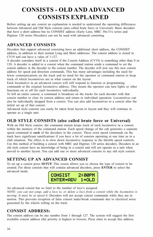
SETTING UP AN ADVANCED CONSISTTo set up a consist press SETUP. This screen allows you to choose the type of consist to becreated. For those consists that will contain advanced decoders, press ENTER to select theadvanced mode.
CONSIST 2:00PMCONSIST 2:00PMCONSIST 2:00PMCONSIST 2:00PMCONSIST 2:00PM
ENTER=ADV 1=OLDENTER=ADV 1=OLDENTER=ADV 1=OLDENTER=ADV 1=OLDENTER=ADV 1=OLD
An advanced consist has no limit to the number of loco’s assigned.NOTE: you can not setup, add a loco to, or delete a loco from a consist while the locomotive ismoving. It must be at speed 0. Decoders will not accept consist commands while they are inmotion. This prevents reception of false consist make/break commands due to electrical noisegenerated by the wheels rolling on the track.
CONSIST ADDRESS:The consist address can be any number from 1 through 127. The system will suggest the firstavailable consist address (the priority is highest to lowest). Press enter to accept this address.

37
SETUP 2:00PMSETUP 2:00PMSETUP 2:00PMSETUP 2:00PMSETUP 2:00PM
CON ADDR: 127CON ADDR: 127CON ADDR: 127CON ADDR: 127CON ADDR: 127
You may enter any other number you wish then press the ENTER key. If you have locomotiveson the layout using short addresses make sure you don’t pick an address already in use. This isone reason to use long addresses with your loco fleet. It will keep the short addresses free forconsists.
ENTERING THE LEAD LOCO NUMBEREntering the lead loco number is optional but recommended. The command station keeps trackof consists by their lead loco number. The locomotive is the loco that the command station willsend function commands to. For example: headlight on/off commands. If the command stationdid not know the lead loco it would not know which locomotive should have the headlight turnedon or off.
The lead loco number also acts as an alias for the consist number entered above. Say you have abunch of consists stored on staging tracks and you wish to operate one of them. After theconsist is set up, you can select the consist by pressing SEL LOCO then entering either the leadloco number or the consist number. The lead loco number is typically easiest to rememberbecause it is the number printed right on the locomotive. The consist address may not relate toany visible or easily remembered number.
SETUP 2:00PMSETUP 2:00PMSETUP 2:00PMSETUP 2:00PMSETUP 2:00PM
LEAD LOCO: _LEAD LOCO: _LEAD LOCO: _LEAD LOCO: _LEAD LOCO: _
Enter the lead loco number followed by pressing the ENTER key.
ENTERING THE LEAD LOCO DIRECTIONIf the locomotive is to operate in the forward direction press ENTER. Press the DIRECTIONkey if you wish to have the locomotive operate in the reverse direction. Subsequent presses ofthe DIRECTION key will keep changing the direction. When you get the direction you desirepress the ENTER key.
CONSIST 2:00PMCONSIST 2:00PMCONSIST 2:00PMCONSIST 2:00PMCONSIST 2:00PM
DIR THIS LOCO: FDIR THIS LOCO: FDIR THIS LOCO: FDIR THIS LOCO: FDIR THIS LOCO: F
This informs the decoder if the loco is in the line-up facing forward or reverse. For instance, inan A-B-A consist the lead A unit and the B unit will be setup in the Forward direction, and thesecond A unit will be setup in the Reverse direction.
ENTERING THE REAR LOCO NUMBEREntering the rear loco number is optional. The command station keeps track of consists by theirlead or rear loco number. If you select the consist by the rear loco number the direction of theconsist will be reversed from the direction of operation if you selected it by the lead loco. Youdon’t have to enter a rear loco number if you don’t need/want to operate the consist in reverse.The rear loco number also act as an alias for the consist number just as the lead loco number.
SETUP 2:00PMSETUP 2:00PMSETUP 2:00PMSETUP 2:00PMSETUP 2:00PM
REAR LOCO: _REAR LOCO: _REAR LOCO: _REAR LOCO: _REAR LOCO: _
Enter the rear loco number followed by the ENTER key.
NOTE: If you plan on dropping the rear loco from the consist later on, DO NOT enter it as therear loco. Enter it later on when prompted for mid-consist locos.

38
ENTERING THE REAR LOCO DIRECTIONIf the locomotive is to operate in the normal direction press ENTER. Press the DIRECTIONkey if you wish to have the locomotive operate in the reverse direction. Subsequent presses ofthe DIRECTION key will keep changing the direction. When you get the direction you desirepress the ENTER key.
CONSIST 2:00PMCONSIST 2:00PMCONSIST 2:00PMCONSIST 2:00PMCONSIST 2:00PM
DIR THIS LOCO: FDIR THIS LOCO: FDIR THIS LOCO: FDIR THIS LOCO: FDIR THIS LOCO: F
ADDING A MID-CONSIST LOCOAt this point you can start to add more locomotives to the consist. Enter the next locomotive(decoder address) followed by pressing the ENTER key. If you don’t want to add any morelocomotives to the consist just press ENTER.
CONSIST 2:00PMCONSIST 2:00PMCONSIST 2:00PMCONSIST 2:00PMCONSIST 2:00PM
ADD LOCO: _ADD LOCO: _ADD LOCO: _ADD LOCO: _ADD LOCO: _
ENTERING THE LOCO’S DIRECTION
CONSIST 2:00PMCONSIST 2:00PMCONSIST 2:00PMCONSIST 2:00PMCONSIST 2:00PM
DIR THIS LOCO: FDIR THIS LOCO: FDIR THIS LOCO: FDIR THIS LOCO: FDIR THIS LOCO: F
As with the lead locomotive, this informs the decoder if the loco is in the line-up facing forwardor reverse.If the locomotive is to operate in the normal direction press ENTER. Press the DIRECTIONkey if you wish to have the locomotive operate in the reverse direction. Subsequent presses ofthe DIRECTION key will keep changing the direction. When you get the direction you desirepress the ENTER key.At this point you will be prompted to add additional locomotives. If you don’t want to add anymore locomotives to the consist just press ENTER or PROG/ESC with out entering an address.
DROPPING A LOCOMOTIVE FROM AN ADVANCED CONSISTTo delete a consist locomotive press DEL
DEL LOCO 2:00PMDEL LOCO 2:00PMDEL LOCO 2:00PMDEL LOCO 2:00PMDEL LOCO 2:00PM
ENTER LOCO: _ENTER LOCO: _ENTER LOCO: _ENTER LOCO: _ENTER LOCO: _
This will drop the loco identified from whatever consist it was part of. There is no need to knowthe consist number for this operation. You cannot drop a lead or rear loco without clearing theentire consist. Deleting a loco sets CV19 to a value of 0 in that loco.
ADDING A LOCO TO AN ADVANCED CONSISTSelect the consist.
ADD LOCO 2:00PMADD LOCO 2:00PMADD LOCO 2:00PMADD LOCO 2:00PMADD LOCO 2:00PM
CONSIST ADDR: _CONSIST ADDR: _CONSIST ADDR: _CONSIST ADDR: _CONSIST ADDR: _
Press ADD . Enter the address of the consist, or lead loco, to which the loco is to be added andthen press the ENTER key.
ADD LOCO 2:00PMADD LOCO 2:00PMADD LOCO 2:00PMADD LOCO 2:00PMADD LOCO 2:00PM
ADD LOCO: _ADD LOCO: _ADD LOCO: _ADD LOCO: _ADD LOCO: _
Enter the loco number to be added and press the ENTER key.

39
Enter the loco’s directionCONSIST 2:00PMCONSIST 2:00PMCONSIST 2:00PMCONSIST 2:00PMCONSIST 2:00PM
DIR THIS LOCO: FDIR THIS LOCO: FDIR THIS LOCO: FDIR THIS LOCO: FDIR THIS LOCO: F
If the loco is to operate in the normal direction press ENTER, otherwise press the DIRECTIONkey followed by pressing the ENTER key. This informs the decoder whether the locomotive is inthe line-up facing forward or reverse.
CLEARING AN ADVANCED CONSIST
Press CLEAR. Select the consist to be cleared.
LOC:4449 2:00PMLOC:4449 2:00PMLOC:4449 2:00PMLOC:4449 2:00PMLOC:4449 2:00PM
KILL CONSIST: _KILL CONSIST: _KILL CONSIST: _KILL CONSIST: _KILL CONSIST: _
Enter the lead or rear loco number and press ENTER. This sends a command to all decoders withthis consist address to clear the consist address from the decoder. You can also enter the consistaddress if you know it. All locomotives that were assigned to this consist will no longer respondto the consist address.
CHANGING THE LEAD/REAR LOCOUnder some circumstances it is desirable to change which locomotive is to act as the lead loco ofa consist. One of these circumstances is when you want to drop the lead/rear loco from theconsist. The command station will not allow you to drop the lead/rear loco so you will want toassign a new locomotive as lead/rear. Then you will be able to drop the old lead loco.
SETUP 2:00PMSETUP 2:00PMSETUP 2:00PMSETUP 2:00PMSETUP 2:00PM
CON ADDR: _CON ADDR: _CON ADDR: _CON ADDR: _CON ADDR: _
The first step is to press SETUP. Then enter either the consist number of the current lead loconumber (address). Then press ENTER.
SETUP 2:00PMSETUP 2:00PMSETUP 2:00PMSETUP 2:00PMSETUP 2:00PM
LEAD LOCO: _LEAD LOCO: _LEAD LOCO: _LEAD LOCO: _LEAD LOCO: _
Enter the new lead loco number and press ENTER. If the new lead loco is to operate in theforward direction press ENTER. Press the DIRECTION key if you wish to have the locomotiveoperate in the reverse direction. When you get the direction you desire press the ENTER key.
CONSIST 2:00PMCONSIST 2:00PMCONSIST 2:00PMCONSIST 2:00PMCONSIST 2:00PM
DIR THIS LOCO: FDIR THIS LOCO: FDIR THIS LOCO: FDIR THIS LOCO: FDIR THIS LOCO: F
You are now finished changing the lead locomotive of the consist.
Use a similar procedure to change the rear loco.

40
OLD STYLE CONSISTS
SETUP AN OLD STYLE CONSIST
CONSIST 2:00PMCONSIST 2:00PMCONSIST 2:00PMCONSIST 2:00PMCONSIST 2:00PM
ENTER=ADV 1=OLDENTER=ADV 1=OLDENTER=ADV 1=OLDENTER=ADV 1=OLDENTER=ADV 1=OLD
Press SETUP. This screen allows you to choose the type of consist to be created. For thoseconsists that will contain any basic decoders, press 1. Please note that the limit on an old styleconsist is four locomotives or advanced consists. NOTE: Once you setup an old style consist youwill not be able to select a new locomotive to run unless you store the consist away by pressingrecall (or clear the consist). Each cab may have up to 6 old style consists in recall.
INITIAL SCREEN DISPLAYED
CON: 000 2:00PMCON: 000 2:00PMCON: 000 2:00PMCON: 000 2:00PMCON: 000 2:00PM
000 000 000 000 000 000 000 000 000 000 000 000 000 000 000
This screen is displayed to show all 4 “slots” for loco’s in the consist are empty. Press theENTER key to continue.
ENTERING THE LEAD LOCO NUMBER
CON: 000 2:00PMCON: 000 2:00PMCON: 000 2:00PMCON: 000 2:00PMCON: 000 2:00PM
ADD LOCO: _ADD LOCO: _ADD LOCO: _ADD LOCO: _ADD LOCO: _
Enter the loco number followed by the ENTER key. The first loco to be added will be the leadloco (the lead loco number will be displayed on the screen during normal operation). The consistwill respond to this number.
ENTERING THE LOCO DIRECTION
SETUP 2:00PMSETUP 2:00PMSETUP 2:00PMSETUP 2:00PMSETUP 2:00PM
DIR THIS LOCO: FDIR THIS LOCO: FDIR THIS LOCO: FDIR THIS LOCO: FDIR THIS LOCO: F
The locomotive direction is assumed to be forward, if it is to operate in reverse press theDIRECTION key. This informs the command station if the loco is in the line-up facing forwardor reverse. This effects only the direction of the loco, not lighting. Press the ENTER key tocontinue.The operator needs to press ADD for every loco to be added. This operation leaves the consistas the active unit for this Cab. By pressing RECALL the operator can change to another loco/consist but the old style consist will stay with this Cab until it is either passed by assigning it toanother Cab or is cleared.
OLD STYLE CONSIST FULL
CON: 012 2:00PMCON: 012 2:00PMCON: 012 2:00PMCON: 012 2:00PMCON: 012 2:00PM
CAN NOT ADD LOCOCAN NOT ADD LOCOCAN NOT ADD LOCOCAN NOT ADD LOCOCAN NOT ADD LOCO
The consist contains four loco’s which is the maximum amount that we support in this style ofconsist. Press the ENTER key to continue.

41
FOLLOW-UP SCREEN
CON: 012 02:00PMCON: 012 02:00PMCON: 012 02:00PMCON: 012 02:00PMCON: 012 02:00PM
CONSIST NOW FULLCONSIST NOW FULLCONSIST NOW FULLCONSIST NOW FULLCONSIST NOW FULL
This screen reaffirms the previous screen. Press the ENTER key to continue.
CON: 042 2:00PMCON: 042 2:00PMCON: 042 2:00PMCON: 042 2:00PMCON: 042 2:00PM
008R 101 4449R 008R 101 4449R 008R 101 4449R 008R 101 4449R 008R 101 4449R
The R indicated that the loco is reversed in the consist.Loco 42is the lead loco (short address of 42).Loco 8is a loco operating backwards.Loco 101 is a locomotive operating forward.Loco 4449is a locomotive operating backwards.
ADDING A LOCO TO AN OLD STYLE CONSIST
CON: 012 2:00PMCON: 012 2:00PMCON: 012 2:00PMCON: 012 2:00PMCON: 012 2:00PM
FWD: 000 L------FWD: 000 L------FWD: 000 L------FWD: 000 L------FWD: 000 L------
With an Old Consist, you can only add a loco to an active consist on your cab. If the consist isnot active press RECALL until you have the consist active or acquire the consist from anothercab by “ASSIGN LOCO TO CAB”.
ENTERING THE LOCO NUMBER
CON: 012 2:00PMCON: 012 2:00PMCON: 012 2:00PMCON: 012 2:00PMCON: 012 2:00PM
ADD LOCO: _ADD LOCO: _ADD LOCO: _ADD LOCO: _ADD LOCO: _
Enter the loco number to add and press ENTER.
ENTERING THE LOCO DIRECTION
CON: 012 2:00PMCON: 012 2:00PMCON: 012 2:00PMCON: 012 2:00PMCON: 012 2:00PM
DIR THIS LOCO: FDIR THIS LOCO: FDIR THIS LOCO: FDIR THIS LOCO: FDIR THIS LOCO: F
If the locomotive is to operate in the forward direction press ENTER. Press the DIRECTIONkey if you wish to have the locomotive operate in the reverse direction. Subsequent presses ofthe DIRECTION key will keep changing the direction. When you get the direction you desirepress the ENTER key.
DROPPING A LOCO FROM AN OLD STYLE CONSIST
CON: 012 2:00PMCON: 012 2:00PMCON: 012 2:00PMCON: 012 2:00PMCON: 012 2:00PM
FWD: 120 L------FWD: 120 L------FWD: 120 L------FWD: 120 L------FWD: 120 L------
You can only delete a loco from an active consist on your cab. If the consist is not active pressRECALL until you have the consist active or acquire the consist from another cab by “ASSIGNLOCO TO CAB”.

42
Press DEL.DEL LOCO 2:00PMDEL LOCO 2:00PMDEL LOCO 2:00PMDEL LOCO 2:00PMDEL LOCO 2:00PM
ENTER LOCO: _ENTER LOCO: _ENTER LOCO: _ENTER LOCO: _ENTER LOCO: _
This will drop the intended locomotive from old style consist. Enter the loco number and thepress ENTER.
ERROR MESSAGE
DEL LOCO 2:00PMDEL LOCO 2:00PMDEL LOCO 2:00PMDEL LOCO 2:00PMDEL LOCO 2:00PM
NOT IN CONSIST:NOT IN CONSIST:NOT IN CONSIST:NOT IN CONSIST:NOT IN CONSIST:
This message will display when the loco selected is not in the active consist.
CLEARING AN OLD STYLE CONSIST
CON:12 2:00PMCON:12 2:00PMCON:12 2:00PMCON:12 2:00PMCON:12 2:00PM
024 056 078 024 056 078 024 056 078 024 056 078 024 056 078
Press CLEAR. You can only clear an old style consist if it is the active consist on your cab. Ifthe consist is not active press RECALL until you have the consist active or acquire the consistfrom another cab by “ASSIGN LOCO TO CAB”.
CONFIRM THAT THE CONSIST IS TO BE KILLED
KILL? 02:00PMKILL? 02:00PMKILL? 02:00PMKILL? 02:00PMKILL? 02:00PM
ENTER=NO 1=YES:ENTER=NO 1=YES:ENTER=NO 1=YES:ENTER=NO 1=YES:ENTER=NO 1=YES:
Press 1 to clear the consist from the Command Station memory. All locomotives that were inthe consist may now be selected and operated independently.

43
CONTROLLING TURNOUTS AND OTHERACCESSORIES
ENTER THE ACCESSORY NUMBER TO BE OPERATED
CONTROL 02:00PMCONTROL 02:00PMCONTROL 02:00PMCONTROL 02:00PMCONTROL 02:00PM
ACC NUMBER: _ACC NUMBER: _ACC NUMBER: _ACC NUMBER: _ACC NUMBER: _
Press SELECT ACCY key. Enter the address of the accessory to be operated. Followed bypressing the ENTER key. Valid accessory addresses range from 1 to 2044.
TURN ACCESSORY ON OR OFF
ACC: 003 02:00PMACC: 003 02:00PMACC: 003 02:00PMACC: 003 02:00PMACC: 003 02:00PM
1=N(ON) 2=R(OFF)1=N(ON) 2=R(OFF)1=N(ON) 2=R(OFF)1=N(ON) 2=R(OFF)1=N(ON) 2=R(OFF)
Press 1 to turn accessory ON. (Switch machine set to Normal)Press 2 to turn accessory OFF. (Switch machine set to Reverse)
44
THE MOMENTUM BUTTONWhen you press the momentum button you are prompted to enter a momentum level. There are9 levels of momentum (1-9) plus ‘direct drive’(0). Pressing a digit button from 0-9 willautomatically set the acceleration and deceleration rates of the locomotive(s) being controlled.Pressing 0 sets the momentum of the train to 0 effectively turning it off. 1 is the smallestamount of momentum, 9 is the most.If you are operating an Advanced or Old Style consist setup in the command station alllocomotives will have their momentum set. If an Old Style consist includes one or moreAdvanced consists all locomotives in the Advanced consist (up to 6 per advanced consist) willalso have their momentum set properly.
Technical stuff - what happens when you set momentum
The digit entered is multiplied by 8 (factory default) and sent to CV3. The value sent to CV4is ½ half (factory default) the value sent to CV3. You can change these multipliers.
You can setup the following momentum parameters in the SET CMD STA menu:
The acceleration multiplier can be set to a value in the range of 0-25.
The deceleration can be set to FULL or HALF the value sent to CV3.
You can disable the sending of momentum commands to consists.
If a decoder follows NMRA Recommended Practice 9.2.2 the rates will be as shown below withthe factory default settings (multiplier = 8 and deceleration = half).
Rate 1 = 7 seconds to full speed, 3 seconds to stop
Rate 2 = 14 seconds to full speed, 7 seconds to stop
Rate 3 = 21 seconds to full speed, 10 seconds to stop
Rate 4 = 28 seconds to full speed, 14 seconds to stop
Rate 5 = 35 seconds to full speed, 17 seconds to stop
Rate 6 = 42 seconds to full speed, 21 seconds to stop
Rate 7 = 49 seconds to full speed, 24 seconds to stop
Rate 8 = 54 seconds to full speed, 27 seconds to stop
Rate 9 = 61 seconds to full speed, 30 seconds to stop
If a consist is active when MOMENTUM is pressed the button will do nothing unless “CONSISTMOMENTUM” is enabled (factory default) in the SET CMD STA menu.Momentum commands will be sent to a limit of 6 locos per Advanced consist.
Notes regarding momentum commands and decoders:There are special commands for setting consist momentum (CV23 and CV24) but many decodersdo not support these CV’s.
CV3 and CV4 are required and have standardized values in decoders per RP-9.2.2.Support for consist CV23 and CV24 is not required in decoders, this is why we use CV3 and CV4for consist momentum..
Sound equipped locomotives that verbally speak the value of CVs must be turned off by settingCV 62 to a value of 0 for momentum to work properly. Setting CV 62 to a value of 1 turns theverbal response back on.

45
USE MACROS TO CONTROL TURNOUTSMACROS EXPLAINEDMacros are really a list of turnouts controlled by accessory decoders that you wish to operate asa group. There are a total of 256 of macros, each one capable of controlling up to 10 turnouts.Macros may be ‘chained’ with other macros to create complex routes with hundreds of turnouts.
ENTER THE MACRO NUMBER TO BE EXECUTED
LOC: 1023 2:00PMLOC: 1023 2:00PMLOC: 1023 2:00PMLOC: 1023 2:00PMLOC: 1023 2:00PM
MACRO NUMBER: _MACRO NUMBER: _MACRO NUMBER: _MACRO NUMBER: _MACRO NUMBER: _
Press MACRO key. Enter the number of the macro (0-256) to be executed Press ENTER.
MACRO NOT SET UP
ERROR: 02:00PMERROR: 02:00PMERROR: 02:00PMERROR: 02:00PMERROR: 02:00PM
-MACRO IS EMPTY--MACRO IS EMPTY--MACRO IS EMPTY--MACRO IS EMPTY--MACRO IS EMPTY-
This message will be displayed if no macro has been programmed for the number entered.
MACRO PROGRAMMINGTo program a macro see the PROGRAMMING MACRO section.

46
PROGRAMMING PROCEDURES
ACCESSING PROGRAMMING MODESTo access the various programming modes, press the PROG key. The following messages will bedisplayed for each press of the PROG key. When the desired mode is displayed, press theENTER key to enter that mode. To quickly get to a programming mode, press the PROG keyand then press the number of the screen. If you have pressed the PROG key by mistake, orwant to exit out without having to press the PROG key several times, press EXPN.Refer to the following sections for the individual programming instructions. To escape from anyprogramming session press the PROG key.
SEL MODE 02:00PMSEL MODE 02:00PMSEL MODE 02:00PMSEL MODE 02:00PMSEL MODE 02:00PM
PROGRAM ON MAINPROGRAM ON MAINPROGRAM ON MAINPROGRAM ON MAINPROGRAM ON MAIN
SEL MODE 02:00PMSEL MODE 02:00PMSEL MODE 02:00PMSEL MODE 02:00PMSEL MODE 02:00PM
ASSIGN LOCO->CABASSIGN LOCO->CABASSIGN LOCO->CABASSIGN LOCO->CABASSIGN LOCO->CAB
SEL MODE 02:00PMSEL MODE 02:00PMSEL MODE 02:00PMSEL MODE 02:00PMSEL MODE 02:00PM
SET SYSTEM CLOCKSET SYSTEM CLOCKSET SYSTEM CLOCKSET SYSTEM CLOCKSET SYSTEM CLOCK
SEL MODE 02:00PMSEL MODE 02:00PMSEL MODE 02:00PMSEL MODE 02:00PMSEL MODE 02:00PM
USE PROGRAM TRKUSE PROGRAM TRKUSE PROGRAM TRKUSE PROGRAM TRKUSE PROGRAM TRK
SEL MODE 02:00PMSEL MODE 02:00PMSEL MODE 02:00PMSEL MODE 02:00PMSEL MODE 02:00PM
SET CMD STATIONSET CMD STATIONSET CMD STATIONSET CMD STATIONSET CMD STATION
SEL MODE 02:00PMSEL MODE 02:00PMSEL MODE 02:00PMSEL MODE 02:00PMSEL MODE 02:00PM
SET CAB PARAMSSET CAB PARAMSSET CAB PARAMSSET CAB PARAMSSET CAB PARAMS
SEL MODE 02:00PMSEL MODE 02:00PMSEL MODE 02:00PMSEL MODE 02:00PMSEL MODE 02:00PM
PROG ACCESSORIESPROG ACCESSORIESPROG ACCESSORIESPROG ACCESSORIESPROG ACCESSORIES
SEL MODE 02:00PMSEL MODE 02:00PMSEL MODE 02:00PMSEL MODE 02:00PMSEL MODE 02:00PM
PROGAM MACROSPROGAM MACROSPROGAM MACROSPROGAM MACROSPROGAM MACROS
SEL MODE 02:00PMSEL MODE 02:00PMSEL MODE 02:00PMSEL MODE 02:00PMSEL MODE 02:00PM
BROWSE CONSISTSBROWSE CONSISTSBROWSE CONSISTSBROWSE CONSISTSBROWSE CONSISTS
SEL MODE 02:00PMSEL MODE 02:00PMSEL MODE 02:00PMSEL MODE 02:00PMSEL MODE 02:00PM
PROGRAM SIGNALSPROGRAM SIGNALSPROGRAM SIGNALSPROGRAM SIGNALSPROGRAM SIGNALS
To program locomotive decoders on themain (OPS mode) press ENTER.
To assign a locomotive/consist to a Cabpress ENTER. [2]
To start, stop, or set the System Clockpress ENTER [3]
To program on the program track pressENTER. [4]
To set command station parameterspress ENTER. [5]
To set the Cab parameters pressENTER. [6]
To program accessory decoders on themain press ENTER. [7]
To setup macros (routing throughturnouts) press ENTER. [8]
To browse through all the advancedconsists in the system, press ENTER [9]
To program accessory decoders on themain press ENTER. [10]

47
PROGRAMMING MENUSTABLE OF CONTENTS
The following is a chart of all of the programming modes and each section within each mode.Refer to the detail in the following sections.
PROGRAMMING ON THE MAIN ...................................................................................... 49WHAT TO PROGRAM .................................................................................................. 49ADDRESS PROGRAMMING (OPTION 1) ................................................................. 49CV PROGRAMMING (OPTION 2) .............................................................................. 50SET DECODER CONFIGURATION (OPTION 3) .................................................... 50SET MOTOR CONTROL PARAMETERS (OPTION 4) .......................................... 51SET UP DECODER OUTPUT/FUNCTION MAPPING (OPTION 5) .................. 53SET UP NCE LIGHTING EFFECTS (OPTION 6) .................................................... 54SOUNDTRAXX TSUNAMI PROGRAMMING (OPTION 7) .................................. 54QSI PROGRAMMING (OPTION 8) ............................................................................. 55BINARY CV PROGRAMMING (OPTION 9) ............................................................. 55
ASSIGNING A LOCO TO A CAB ......................................................................................... 56ASSIGN THE LOCO ....................................................................................................... 56ASSIGN THE CAB ........................................................................................................... 56
SET THE SYSTEM CLOCK ................................................................................................. 57STOPPING THE CLOCK .............................................................................................. 57SETTING 12 OR 24 HOUR MODE ............................................................................. 57ENTERING THE HOUR ................................................................................................ 57ENTERING THE MINUTE ........................................................................................... 57ENTERING THE RATIO ............................................................................................... 57STARTING THE CLOCK ............................................................................................... 57
PROGRAMMING TRACK .................................................................................................... 58PROGRAMMING OPTIONS ......................................................................................... 58STANDARD PROGRAMMING (OPTION 1) ............................................................. 59
DECODER MANUFACTURER ................................................................................ 59DECODER VERSION ................................................................................................. 59DISPLAY OF ACTIVE ADDRESS ............................................................................ 59SETTING UP BASIC DECODER CONFIGURATION (CV29) ........................... 60
DIRECTION BIT ............................................................................................... 61SPEED STEPS ......................................................................................................... 61ANALOG MODE .................................................................................................... 61SPEED TABLE SELECTION ............................................................................... 61ENABLE LONG OR SHORT ADDRESS ............................................................. 61
SETTING UP MOTOR CONTROL PARAMETERS ............................................ 62START VOLTAGE .................................................................................................. 62MAXIMUM VOLTAGE ......................................................................................... 62MID SPEED ............................................................................................................. 62ACCELERATION ................................................................................................... 62DECELERATION ................................................................................................... 63MOTOR PWM FREQUENCY .............................................................................. 63NCE TORQUE COMPENSATION KICK RATE .............................................. 63NCE TORQUE COMPENSATION KICK DEPTH ........................................... 63SET UP DECODER OUTPUT/FUNCTION MAPPING ................................. 64
CONFIGURATION VARIABLE (CV) PROGRAMMING (OPTION 1) .................. 64SET ANY CV (OPTION 2) ............................................................................................ 65REGISTER PROGRAMMING (OPTION 3) ................................................................ 65PAGED PROGRAMMING (OPTION 4) ...................................................................... 66DIRECT PROGRAMMING (OPTION 5) .................................................................... 66SET UP NCE LIGHTING EFFECTS (OPTION 6) .................................................... 66RECOVERY PROGRAMMING (OPTION 7) .............................................................. 66

48
SETUP COMMAND STATION .................................................................................... 67DISPLAY SOFTWARE VERSION AND DATE ..................................................... 67
NUMBER OF STOP PACKETS ........................................................................... 67NUMBER OF TEMP PACKETS .............................................................................. 67NUMBER OF ACCESSORY PACKETS ................................................................... 67NUMBER OF HORN OFF PACKETS ...................................................................... 67NUMBER OF PROGRAM PACKETS ...................................................................... 68TEST FOR LOCO IN USE ......................................................................................... 68SEND FUNCTION COMMANDS TO CONSIST ADDRESS ................................ 68CONSIST MOMENTUM ........................................................................................... 68MOMENTUM MULTIPLIER .................................................................................. 68MOMENTUM DECELERATION RATE ................................................................ 68EMERGENCY STOP LAYOUT SHUTDOWN ...................................................... 69RADIO FIX ENABLE ................................................................................................ 69AIU BROADCAST ENABLE .................................................................................... 69RS232 PORT BAUD RATE ....................................................................................... 69SYSTEM RESET ......................................................................................................... 69FUNCTION REFRESH RATE ................................................................................... 69MEMORY BACKUP OPTIONS ............................................................................... 70HIGHEST CAB TO PROGRAM ON MAIN ............................................................ 71LAST CAB TO ASSIGN LOCO ................................................................................. 71LAST CAB TO SET CLOCK .................................................................................... 71LAST CAB TO USE PROGRAM TRACK .............................................................. 71LAST CAB TO SET COMMAND STATION ......................................................... 71LAST CAB TO SET ITSELF .................................................................................... 71LAST CAB TO PROGRAM ACCESSORIES ........................................................... 71LAST CAB TO PROGRAM MACROS .................................................................... 71LAST CAB TO PROGRAM SIGNALS ..................................................................... 72
SET CAB PARAMETERS .............................................................................................. 73NUMBER OF RECALLS ............................................................................................ 73CLEAR RECALLS ....................................................................................................... 73SETTING THE CAB ADDRESS ............................................................................... 73ASSIGNING THE HORN/WHISTLE FUNCTION ................................................ 74ASSIGNING THE BELL FUNCTION ...................................................................... 74
PROGRAM ACCESSORY DECODERS ......................................................................... 75PROGRAM MACROS ...................................................................................................... 76
ENTER THE ACCESSORY ADDRESS/LINKING MACROS ............................... 76BROWSE CONSISTS ....................................................................................................... 78PROGRAM SIGNAL DECODERS ................................................................................. 79

49
PROGRAMMING ON THE MAINProgramming on the Main is also called Operations (OPS) Mode programming. OPSprogramming allows you to change parameters while the loco is on the main track (even whileit’s running). This does not affect other locomotives on the track. You can even change thelocomotive address.
OPS PROG 02:00PMOPS PROG 02:00PMOPS PROG 02:00PMOPS PROG 02:00PMOPS PROG 02:00PM
PROG LOCO: 003PROG LOCO: 003PROG LOCO: 003PROG LOCO: 003PROG LOCO: 003
We first begin by telling the system which locomotive to program. If you want to program thelocomotive you are currently operating just press ENTER. If you wish to program a differentlocomotive just enter its address at the above prompt.
WHAT TO PROGRAMAfter determining which locomotive you wish to program you will see the following display. ThePower Pro system provides 9 different OPs mode programming options.
LOC:1022 02:00PMLOC:1022 02:00PMLOC:1022 02:00PMLOC:1022 02:00PMLOC:1022 02:00PM
1=ADR 2=CV 3=CFG1=ADR 2=CV 3=CFG1=ADR 2=CV 3=CFG1=ADR 2=CV 3=CFG1=ADR 2=CV 3=CFG
The first three options are displayed. Press ENTER to see more options. For example: If youwish to set the locomotive address press 1, if you want to program CVs press 2.
Descriptions of each programming option are described below.
1 ........................ SET UP LOCOMOTIVE ADDRESS2 ........................ CHANGE ANY CV IN THE DECODER3 ........................ SET UP THE DECODER CONFIGURATION (CV29)4 ........................ MOTOR CONTROL5 ........................ FUNCTION MAP6 ........................ NCE EFFECTS7 ........................ SOUNDTRAXX8 ........................ QSI SOUND9 ........................ BIN CV
ADDRESS PROGRAMMING (Option 1)This option provides a means by which to program the address of your locomotive. Mostdecoders allow programming of the locomotive address while on the mainline. The first thing todo is decide if you want to program a long or short address into the locomotive.
SET ADDR 03:38PMSET ADDR 03:38PMSET ADDR 03:38PMSET ADDR 03:38PMSET ADDR 03:38PM
1=LONG 2=SHORT1=LONG 2=SHORT1=LONG 2=SHORT1=LONG 2=SHORT1=LONG 2=SHORT
In DCC there are 2 kinds of addresses (loco numbers), long and short. Short addresses range from1 to 127 and long addresses range from 0-9999. We normally recommend using long addressesfor all your locomotives. Consists require the use of a short address so it is better to conserveshort addresses by using long addresses for individual locomotives. Push the digit button thatcorresponds the type address you wish to program. You will then be presented with the displaybelow.
SET ADDR 03:38PMSET ADDR 03:38PMSET ADDR 03:38PMSET ADDR 03:38PMSET ADDR 03:38PM
LONG ADDR: _LONG ADDR: _LONG ADDR: _LONG ADDR: _LONG ADDR: _

50
Enter the new address for the locomotive. The new address will be sent to the locomotive andyou will be returned to the normal display with the locomotive selected and ready to run. Mostdecoders allow programming the address while on the mainline. If you are using a locomotivewith a sound decoder from QSI you will need to turn off verbal programming acknowledgment(set CV62 to 0) for the address to be set properly. If your locomotive does not allow setting theaddress on the mainline you will need to set it on the programming track. You can press PROG/ESC to escape out of setting the address without affecting anything in the decoder. Nocommands are sent until you press ENTER after typing in the address.
CV PROGRAMMING (Option 2)This option allows you to change any configuration variable (range of 1-999) in your decoder.
ENTER CONFIGURATION VARIABLE NUMBERAll configuration variables can be set while on the mainline. Just pressing ENTER without typingin a number will return you to the main OPS programming prompt. Pressing PROG/ESC willcompletely exit from programming and return you to the normal display.
PROG CV 02:00PMPROG CV 02:00PMPROG CV 02:00PMPROG CV 02:00PMPROG CV 02:00PM
ENTER CV NUM: _ENTER CV NUM: _ENTER CV NUM: _ENTER CV NUM: _ENTER CV NUM: _
ENTER THE VALUE
The value to be programmed into the CV should be entered at the above prompt. PressingPROG/ESC before or during number entry will completely exit from programming and returnyou to the normal display.
PROG CV 02:00PMPROG CV 02:00PMPROG CV 02:00PMPROG CV 02:00PMPROG CV 02:00PM
ENTER VALUE: _ENTER VALUE: _ENTER VALUE: _ENTER VALUE: _ENTER VALUE: _
SET DECODER CONFIGURATION (Option 3)This option will setup the various decoder configuration parameters. There are six of theseparameters squeezed into one CV. You will be asked a series of questions regarding the basicoperation of the locomotive. If you are in doubt about the proper answer just press ENTER andyou will usually be OK.
DIRECTION BIT - NORMAL OR REVERSEPress ENTER for the locomotive to operate in the normal direction or press 1 to switch thedirection of operation.
DIR BIT? 02:00PMDIR BIT? 02:00PMDIR BIT? 02:00PMDIR BIT? 02:00PMDIR BIT? 02:00PM
ENTER=NORM 1=REVENTER=NORM 1=REVENTER=NORM 1=REVENTER=NORM 1=REVENTER=NORM 1=REV
SPEED STEPS - 28 OR 14
Press ENTER. All decoders made since 1997 support 28 speeds. NOTE: If you are wonderinghow to set the decoder for 128 speed operation, you do not have to program anything. 128speed mode is always enabled in decoders that support 128 speed step operation.
SPEED 02:00PMSPEED 02:00PMSPEED 02:00PMSPEED 02:00PMSPEED 02:00PM
ENTER=28 1=14 _ENTER=28 1=14 _ENTER=28 1=14 _ENTER=28 1=14 _ENTER=28 1=14 _

51
DC (Analog) MODEPress ENTER to turn DC operation mode off, press 1 to turn DC mode on. We recommendleaving DC mode off for most layouts. This is to prevent all your locomotives from taking offat once in case of a failure in your power station or someone accidentally connecting the trackto a DC power supply (it happens more often than you might think).
DC MODE 02:00PMDC MODE 02:00PMDC MODE 02:00PMDC MODE 02:00PMDC MODE 02:00PM
ENTER=NO 1=YES_ENTER=NO 1=YES_ENTER=NO 1=YES_ENTER=NO 1=YES_ENTER=NO 1=YES_
ADVANCED ACKNOWLEDGEPress ENTER to turn Advanced Acknowledge mode off, press 1 to turn Advanced Acknowledgemode on.
ADV ACK? 02:00PMADV ACK? 02:00PMADV ACK? 02:00PMADV ACK? 02:00PMADV ACK? 02:00PM
ENTER=NO 1=YES _ENTER=NO 1=YES _ENTER=NO 1=YES _ENTER=NO 1=YES _ENTER=NO 1=YES _
NOTE: advanced acknowledgment is not operational in any decoders at this time as the NMRAhas not defined how it is to work.
SPEED TABLE SELECTIONIf the Standard Speed Table is to be used, press ENTER. If the Alternate (uploadable) Speed Tablein the decoder is to be used, press 1.
SPEEDTBL 02:00PMSPEEDTBL 02:00PMSPEEDTBL 02:00PMSPEEDTBL 02:00PMSPEEDTBL 02:00PM
ENTER=STD 1=ALT_ENTER=STD 1=ALT_ENTER=STD 1=ALT_ENTER=STD 1=ALT_ENTER=STD 1=ALT_
ENABLE LONG OR SHORT ADDRESSThe short address is used when operating on DCC systems that do not use long addresses.
ADDRESS 02:00PMADDRESS 02:00PMADDRESS 02:00PMADDRESS 02:00PMADDRESS 02:00PM
ENTER=S 1=LONG:_ENTER=S 1=LONG:_ENTER=S 1=LONG:_ENTER=S 1=LONG:_ENTER=S 1=LONG:_
SET MOTOR CONTROL PARAMETERS (Option 4)This option can be used to setup the various locomotive motor speed control parameters. Youcan skip adjusting any of these parameters (CVs) by pressing ENTER without entering The firstadjustment is:
START VOLTAGE (CV2)Start voltage is the amount of voltage the decoder sends to the motor when a speed step 1command is sent to the locomotive. This is some extra voltage to help get the motor running.You can put in any value from 0-255. If you put in a value of 10 then 10/255 (about 4%) of thefull motor voltage will be applied to the motor at speed step 1.
OPS PROG 11:22AMOPS PROG 11:22AMOPS PROG 11:22AMOPS PROG 11:22AMOPS PROG 11:22AM
START VOLTS: _START VOLTS: _START VOLTS: _START VOLTS: _START VOLTS: _
In most decoders the start voltage is added to each speed step. A good way to setup the StartVoltage is to first set your throttle to speed 1 then go into this Start Voltage programming andtry different values until you get the desired starting speed. This approach can be used with mostof the motor speed adjustments. You may exit programming at any time by pressing PROG/ESC.

52
MAXIMUM VOLTAGE (CV5)This is the amount of voltage applied to the motor at full speed. A value of 255 means send thefull available track voltage to the motor. Lower numbers will tell the decoder to sendproportionally less voltage when full speed is called for.
OPS PROG 11:22AMOPS PROG 11:22AMOPS PROG 11:22AMOPS PROG 11:22AMOPS PROG 11:22AM
MAX VOLTAGE: _MAX VOLTAGE: _MAX VOLTAGE: _MAX VOLTAGE: _MAX VOLTAGE: _
A value of 192 will cut the maximum speed to 192/255 (about 75%) of the track voltage. Mostdecoders interpret a value of 0 to mean 255.
MID SPEED VOLTAGE (CV6)This is the amount of voltage applied to the motor when the middle speed step (14 or 64depending on speed mode) is requested. A value of 128 means to send about ½ the available trackvoltage (128/255 of the voltage) to the motor.
OPS PROG 11:22AMOPS PROG 11:22AMOPS PROG 11:22AMOPS PROG 11:22AMOPS PROG 11:22AM
MID VOLTAGE: _MID VOLTAGE: _MID VOLTAGE: _MID VOLTAGE: _MID VOLTAGE: _
Lower or higher values will send proportionally higher or lower voltages at mid-speed. Mostdecoders interpret a value of 0 to mean 128.
ACCELERATION (CV3)With this CV set to 0 the decoder will be in what is commonly called ‘direct drive’. The decoderwill instantly jump to the speed requested by the throttle. You can add momentum by adjustingthis parameter.
OPS PROG 11:22AMOPS PROG 11:22AMOPS PROG 11:22AMOPS PROG 11:22AMOPS PROG 11:22AM
ACCELERATION: _ACCELERATION: _ACCELERATION: _ACCELERATION: _ACCELERATION: _
A value of 1 will force a delay of .007 seconds between speed steps in 128 speed mode (.032seconds in 28 speed mode). This is equivalent to .896 seconds (.007 x 128 speeds) to go fromspeed 0 to full speed. A value of 10 will yield about 8.9 seconds to full speed.
DECELERATION (CV4)Deceleration works to delay the slowing down of the motor with the same timing asacceleration.
OPS PROG 11:22AMOPS PROG 11:22AMOPS PROG 11:22AMOPS PROG 11:22AMOPS PROG 11:22AM
DECELERATION: _DECELERATION: _DECELERATION: _DECELERATION: _DECELERATION: _
MOTOR PWM FREQUENCY (CV9)DCC decoders almost always drive the motor of the locomotive with Pulse Width Modulation(PWM). This is a series of full voltage pulses that vary in width from very narrow for low motorspeed to very wide providing higher power to the motor. How often the pulses are sent is calledthe frequency.
OPS PROG 11:22AMOPS PROG 11:22AMOPS PROG 11:22AMOPS PROG 11:22AMOPS PROG 11:22AM
PWM FREQ: _PWM FREQ: _PWM FREQ: _PWM FREQ: _PWM FREQ: _
The frequency is adjustable on some decoders. Settings for this CV vary so consult your decodermanual for the proper value. If your decoder is capable of ‘silent’ operation usually a 0 isrequired.

53
NCE TORQUE COMPENSATION KICK RATE (CV116)Newer NCE decoders provide Torque Compensation for smooth low speed operation. TorqueCompensation gives a steady stream of ‘kicks’ to the motor when running at very low speeds.You can adjust how often the motor is kicked (Kick Rate) and how hard it is kicked (KickStrength). CV116 controls the rate.
OPS PROG 11:22AMOPS PROG 11:22AMOPS PROG 11:22AMOPS PROG 11:22AMOPS PROG 11:22AM
KICK RATE: _KICK RATE: _KICK RATE: _KICK RATE: _KICK RATE: _
The typical value is 2-4 with the maximum practical value of about 6. The smaller the numberthe more often the motor gets a brief voltage kick. A value of 0 turns off the kick. A value of 1gives continuous kicks to the motor (not very useful). When using Torque Compensation set theStart Voltage to 0 for best operation.
NCE TORQUE COMPENSATION KICK DEPTH (CV117)This is how hard the motor is kicked at low speed. Typical values range from 1 to 40. Highquality motors (Kato) need very little kick strength where lower quality motors such as oldAthearn and LifeLike need relatively (30-50) large values for slow speed crawling,
OPS PROG 11:22AMOPS PROG 11:22AMOPS PROG 11:22AMOPS PROG 11:22AMOPS PROG 11:22AM
KICK DEPTH: _KICK DEPTH: _KICK DEPTH: _KICK DEPTH: _KICK DEPTH: _
Tips for setting up T/C (Torque Compensation):·Start by setting the locomotive speed to 1 on your throttle.·Adjust the Kick Rate to 4.·Set the Kick Depth to 20 then adjust this value up or down until the locomotive just barelycrawls.It may be easier to set the T/C with the body shell removed from the locomotive so that youcan see the flywheels turn. When you get fairly good slow speed operation go back to the KickRate and try bumping the value up by 1 or 2 to see if the operation improves.
DECODER OUTPUT/FUNCTION MAPPING (Option 5)General Discussion of function mappingFunction mapping is used to customize which lighting outputs (or sound effects) are controlledby which function keys on your handheld throttle. Each function command, F0 through F12, isassigned a unique CV that allows the corresponding function command to be redirected to up to14 different lighting outputs or sound effects.A single function key can control more than one output if desired.It is also possible for one output to be controlled by multiple function keys. In this case, theoutput will be turned on when any of the corresponding function keys are active. That outputwill turn off only when all relevant inputs have also been turned off.Note that all function commands cannot be mapped to all outputs. The LCD display on yourProCab will indicate only those outputs that can be mapped to each function command.The F0 function has two CVs - one for forward direction and one for reverse. Function outputsmapped to these CVs will be directional unless the same output is mapped to both CVs. CVs 33and 34 are both for the F0 function.On NCE decoders CV33 and CV34 do not provide directionality (see SETUP NCE LIGHTINGEFFECTS below) but otherwise operate the same as above. With NCE decoders direction ofoperation for function outputs is provided by the lighting effects CVs (120 through 127).Lenz and TCS decoders do not follow NMRA standard function mapping procedures.When you select function mapping you are prompted for the function number to map.
PRESS FUNCTIONPRESS FUNCTIONPRESS FUNCTIONPRESS FUNCTIONPRESS FUNCTION
NUMBER TO MAPNUMBER TO MAPNUMBER TO MAPNUMBER TO MAPNUMBER TO MAP

54
The top line of the LCD displays the function number and the output numbers that can becontrolled by the function.
F2 12345678F2 12345678F2 12345678F2 12345678F2 12345678
OUTPUTS: —4——OUTPUTS: —4——OUTPUTS: —4——OUTPUTS: —4——OUTPUTS: —4——
Pressing a digit key will enable the output on the decoder when the function is activated.Pressing the same digit key again will disable the output. In the display above the 4 key has beenpressed so that output number 4 will activate when ever the F2 button is pressed on yourhandheld cab. If you were to press another digit such a 6, both output 4 and output 6 will becontrolled by pressing F2.
When mapping functions higher than 3, the top line of the LCD will use small numbers toindicate the output numbers 10 through 14. To enable/disable these high numbers press the digitkey that is 10 less than the output number. Example: press 0 for output 10, 1 for output 11, etc.Pressing PROG/ESC will exit from mapping at any time.
SETUP NCE LIGHTING EFFECTS (Option 6)You can use this option to customize the lighting effects for your NCE decoder equippedlocomotives. This programming option will only work with NCE decoders.
NCE EFX 07:04NCE EFX 07:04NCE EFX 07:04NCE EFX 07:04NCE EFX 07:04
AMOUTPUTNUMBER:_AMOUTPUTNUMBER:_AMOUTPUTNUMBER:_AMOUTPUTNUMBER:_AMOUTPUTNUMBER:_
Function outputs are numbered from 1 to 14. Do not confuse Output numbers with Functionnumbers. The headlight is always output 1 and the reverse light is usually output 2. You areprompted for the output number to setup. Press the output number followed by ENTER.
OUTPUT NUMBER:03OUTPUT NUMBER:03OUTPUT NUMBER:03OUTPUT NUMBER:03OUTPUT NUMBER:03
USE THUMBWHEELUSE THUMBWHEELUSE THUMBWHEELUSE THUMBWHEELUSE THUMBWHEEL
Use the thumbwheel or up/down speed buttons to scroll through the different lighting effectoptions. Press ENTER when you get the one you want.
DIR OF OPERATIONDIR OF OPERATIONDIR OF OPERATIONDIR OF OPERATIONDIR OF OPERATION
1=FW 2=RV 3=BOTH1=FW 2=RV 3=BOTH1=FW 2=RV 3=BOTH1=FW 2=RV 3=BOTH1=FW 2=RV 3=BOTH
Next press 1,2 or 3 to select the ‘directionality’ of the output. If you want the output activeonly in the forward direction of travel - press 1. Press 2 for the effect to operate only whentravelling in reverse. 3 activates the output no matter which direction the locomotive istravelling.
REGULAR BULB ORREGULAR BULB ORREGULAR BULB ORREGULAR BULB ORREGULAR BULB OR
LED 1=BULB 2=LEDLED 1=BULB 2=LEDLED 1=BULB 2=LEDLED 1=BULB 2=LEDLED 1=BULB 2=LED
Last, press 1 if the output has a regular incandescent bulb attached. Press 2 if the output has anLED connected. LEDs behave differently when dimmed than incandescent bulbs. Pressing 1 or 2informs the decoder which set of lighting characteristics to use for this output.
SOUNDTRAXX TSUNAMI PROGRAMMING (Option 7)Soundtraxx Tsunami decoders have a special indexed programming method for setting up soundand lighting effects. When programming CVs 120-127 you will be asked for an index numberbefore you are asked for the CV value. CV119 is then automatically set with the index value

55
before the CV is set with the desired data. All other CVs are programmed in the same manner asOption 2 (CV PROGRAMMING).
QSI PROGRAMMING (Option 8)QSI sound decoders use indexed programming of CV51,CV52,and CV56. You are asked for anindex number before you are asked for the CV value. CV49 is then automatically set with theindex value before the original CV is set with the desired data.When programming CV56 you are asked for primary and secondary index numbers before youare asked for the CV value. CV49 and CV50 are then automatically set with the index numbersbefore CV53 is set with the desired data.All other CV’s are programmed in the normal manner.
BINARY CV PROGRAMMING (Option 9)Use this option if you need to build up the value for a CV bit-by-bit. Enter the CV number youwish to program.
BIN PROG 02:10AMBIN PROG 02:10AMBIN PROG 02:10AMBIN PROG 02:10AMBIN PROG 02:10AM
ENTER CV NUM: _ENTER CV NUM: _ENTER CV NUM: _ENTER CV NUM: _ENTER CV NUM: _
Then press bit number (top line of LCD has bit numbers) to toggle the corresponding individualbits on the lower line of the LCD that make up a binary byte. In the example below the 1,3 and7 keys have been pressed to set the corresponding bits in the byte. To set the value of a bit backto 0 press the bit number again.
CV: 060 76543210CV: 060 76543210CV: 060 76543210CV: 060 76543210CV: 060 76543210
BITS: 10001010BITS: 10001010BITS: 10001010BITS: 10001010BITS: 10001010
When you get the value built up to the number you desire, press ENTER to program the CV.

56
ASSIGNING A LOCO TO A CAB(shortcut = PROG 2 )
This selection passes a loco from one cab to another. This is especially useful when the otheroperator is a novice or has a Basic Cab. The locomotive/consist is passed to the assigned cab andthe locomotive/consist controlled by the other cab is passed back to the original cab. In effectthe locomotives controlled by the cabs are “swapped”. This way you will not accidentally ‘lose’a locomotive in the system.
ASSIGN THE LOCOEnter the loco/consist number you want to assign to another cab, then press ENTER. If you wantto assign the loco you are currently running just push ENTER.
ASSIGN 02:00PMASSIGN 02:00PMASSIGN 02:00PMASSIGN 02:00PMASSIGN 02:00PM
WHICH LOCO: _003WHICH LOCO: _003WHICH LOCO: _003WHICH LOCO: _003WHICH LOCO: _003
ASSIGN THE CABYou need to know the address of the cab you want to ‘receive’ the loco you are assigning. Enterthe Cab number then press ENTER.
LOC:1234 02:00PMLOC:1234 02:00PMLOC:1234 02:00PMLOC:1234 02:00PMLOC:1234 02:00PM
TO WHICH CAB? _TO WHICH CAB? _TO WHICH CAB? _TO WHICH CAB? _TO WHICH CAB? _
This operation is also useful to transfer an old style consist to a smaller cab without thecapability of setting up consists.

57
SET THE SYSTEM CLOCK(shortcut = PROG 3)
This allows the operator to start/stop the clock, set it, choose 12 or 24 hour operation, orchange the fast clock ratio.
STOPPING THE CLOCKPress 1 to stop the clock, press ENTER to leave the clock running and continue with clockprogramming. If the clock is already stopped, you will be prompted to start it.
STOP? 02:00PMSTOP? 02:00PMSTOP? 02:00PMSTOP? 02:00PMSTOP? 02:00PM
ENTER=NO 1=STOPENTER=NO 1=STOPENTER=NO 1=STOPENTER=NO 1=STOPENTER=NO 1=STOP
SETTING 12 or 24 HOUR MODEPress 1 for 12 hour mode, press ENTER for 24 hour mode.
SET TIME 02:00PMSET TIME 02:00PMSET TIME 02:00PMSET TIME 02:00PMSET TIME 02:00PM
1=12HR 2=24HR _1=12HR 2=24HR _1=12HR 2=24HR _1=12HR 2=24HR _1=12HR 2=24HR _
ENTERING THE HOUREnter the starting hour in 24 hour format. For times in the A.M. use 0 to 11. For times in theP.M. use 12 to 23. Press ENTER.
SET TIME 02:00PMSET TIME 02:00PMSET TIME 02:00PMSET TIME 02:00PMSET TIME 02:00PM
ENTER HOURS: _ENTER HOURS: _ENTER HOURS: _ENTER HOURS: _ENTER HOURS: _
ENTERING THE MINUTEEnter the starting minute. Use 0 through 59. Press ENTER.
SET TIME 02:00PMSET TIME 02:00PMSET TIME 02:00PMSET TIME 02:00PMSET TIME 02:00PM
ENTER MINUTES: _ENTER MINUTES: _ENTER MINUTES: _ENTER MINUTES: _ENTER MINUTES: _
ENTERING THE RATIOenter the ratio that the clock should run at with 1 being the normal speed. The ratio can be anynumber from 1:1 to 15:1. Press ENTER.
SET TIME 02:00PMSET TIME 02:00PMSET TIME 02:00PMSET TIME 02:00PMSET TIME 02:00PM
ENTER RATIO: _ENTER RATIO: _ENTER RATIO: _ENTER RATIO: _ENTER RATIO: _
STARTING THE CLOCKIf the clock was stopped, entering SET THE SYSTEM CLOCK will display this screen to let youstart (or restart) the clock. Press 1 to start the clock, press ENTER to leave the clock stoppedand continue with clock programming (see above).
START? 02:00PMSTART? 02:00PMSTART? 02:00PMSTART? 02:00PMSTART? 02:00PM
ENTER=NO 1=STARTENTER=NO 1=STARTENTER=NO 1=STARTENTER=NO 1=STARTENTER=NO 1=START

58
USE PROGRAM TRACK (shortcut = PROG 4)Locomotive decoders remember their operating parameters such as the address, start voltage andlighting effect setups in the decoder’s memory. Each storage location is called a ConfigurationVariable, or CV for short. There is usually a CV for each programmable parameter. The PowerPro allows you to change any or all of the CVs in the loco, including the address. These variableswill remain as programmed until you change them. Programming on the Main (covered earlier inthis manual) is very useful for modifying one, two or a few CVs while the locomotive is out onthe layout. The Program Track is useful for more intensive initial setup of a locomotive. Thebiggest advantage is the ability to read out the values of CVs already setup in the locomotivedecoder.Please note: The programming track does not supply enough power to run your locomotive. Ithas enough power to program the decoder but not enough to cause damage to a miswired decoderor run a motor. You can only run trains on the main track. We recommend that you always tryout a newly installed decoder on the Program Track first. If you can ‘read’ a decoder in theProgram Track you can reasonably expect that it is wired correctly and working properly.
PROGRAMMING OPTIONSJust as with Programming on the Main there are several menu options you can select. ThePower Pro system provides 7 different Program Track options.Descriptions of each programming option are described below.
1 = STANDARD DECODER SETUP, including
Address, Configuration and Function Mapping.
2 = CHANGE ANY CV IN THE DECODER
Reads and programs CVs 1-999.
3 = SET UP THE DECODER CONFIGURATION (CV29)
Change direction of operation, analog mode on/off, 14 or 28 speed mode, long orshort address, factory or custom speed table.
4 = PAGED MODE PROGRAMMING
Force the system to use paged mode programming.
5 = DIRECT MODE PROGRAMMING
Force the system to use direct mode programming.
6 = NCE EFFECTS
Setup NCE lighting effects.
7 = RECOVERY PROGRAMMING
Reprograms selected decoder CVs in an attempt to get an ‘insane’ decoder back tosomewhat normal operation.
The first three options are displayed below. Press ENTER to see more options. For example: Ifyou wish to use program the “Standard” locomotive parameters, press 1, if you want to programdecoder CVs press 2.
PROG TRK 02:00PMPROG TRK 02:00PMPROG TRK 02:00PMPROG TRK 02:00PMPROG TRK 02:00PM
1=STD 2=CV 3=REG1=STD 2=CV 3=REG1=STD 2=CV 3=REG1=STD 2=CV 3=REG1=STD 2=CV 3=REG
This screen allows the user to select the method of programming to suit the decoder you areusing. There are 7 programming options when using the program track. STD programming(option 1) will automatically determine whether to use the Direct or Paged programmingmethods. Paged programming is used by older decoders and can take up to fifteen seconds to readeach CV. Direct mode is newer and generally reads CVs in one to two seconds. For variousreasons you may wish to ‘force’ the programming method to one or the other types. You can

59
press 4 for paged programming or press 5 for direct programming. Standard sets the mostcommon decoder parameters.
STANDARD PROGRAMMING (Option 1)This option automatically determines if the decoder supports Direct or Paged programming anduses the appropriate method for subsequent programming operations. Use this option for initialsetup of your decoder. You will be advised about the manufacturer and the version of the decodersoftware. You will also be able to setup the decoder address, basic configuration, motor control,NMRA standard function mapping and finally any additional CVs you may wish to program.
DECODER MANUFACTURERThis is the NMRA assigned manufacturer number of the decoder. All NCE decoders respond with11. Press ENTER to continue.
MAIN OFF 02:00PMMAIN OFF 02:00PMMAIN OFF 02:00PMMAIN OFF 02:00PMMAIN OFF 02:00PM
MANUFACTURER:011MANUFACTURER:011MANUFACTURER:011MANUFACTURER:011MANUFACTURER:011
You may get this error message:
MAIN OFF 02:00PMMAIN OFF 02:00PMMAIN OFF 02:00PMMAIN OFF 02:00PMMAIN OFF 02:00PM
CAN NOT READ CVCAN NOT READ CVCAN NOT READ CVCAN NOT READ CVCAN NOT READ CV
This means the decoder did not respond to attempts to read this parameter value in thedecoder. There are several things that can cause a failure to read: a miswired decoder,broken or missing track pickup wires, the motor is not connected to the decoder, defectivedecoder, wires to the program track are disconnected, etc. All decoders require that a motor(or similar ‘load’) be connected to the decoder for proper reading on the program track.Decoders that draw too much power from the program track can also cause this message.Most sound decoders draw large amounts of current. The Power Pro can supply the NMRAlimit of ¼ Amp of current for initial ‘charging’ of these decoders and 160mA of continuouscurrent for normal program track operations. If the decoder exceeds these capabilities youwill get the error message. Press ENTER to continue. You will probably still be able toprogram by ignoring the error. Press ENTER, then proceed in the usual manner.
DECODER VERSIONThis display indicates the programming method in use on the top line and the version number ofthe software in the decoder on the bottom line. Press ENTER to continue.
DIR MODE 02:00PMDIR MODE 02:00PMDIR MODE 02:00PMDIR MODE 02:00PMDIR MODE 02:00PM
DECODER VER: 041DECODER VER: 041DECODER VER: 041DECODER VER: 041DECODER VER: 041
DISPLAY OF ACTIVE ADDRESSThe current active address (long or short) is indicated on the top line of the display. If you wishto change the decoder address press 1. Any other button will skip programming the address andcontinue standard programming.
ACTIVE ADR:SHORTACTIVE ADR:SHORTACTIVE ADR:SHORTACTIVE ADR:SHORTACTIVE ADR:SHORT
SETUP ADDR 1=YESSETUP ADDR 1=YESSETUP ADDR 1=YESSETUP ADDR 1=YESSETUP ADDR 1=YES

60
ENTERING THE DECODER (LOCOMOTIVE) ADDRESSThe short address is displayed first. If you wish to change it type in the new address and pressENTER. If you wish to keep it unmodified just press ENTER to skip to the display of the longaddress.
ACTIVE ADR:SHORTACTIVE ADR:SHORTACTIVE ADR:SHORTACTIVE ADR:SHORTACTIVE ADR:SHORT
SHORT ADDR: 003SHORT ADDR: 003SHORT ADDR: 003SHORT ADDR: 003SHORT ADDR: 003
If you put in a new address you will see the following LCD screen asking if you wish to make thisaddress the primary address. Only one address can be the primary address – the long or the short.You cannot have both active at the same time. The decoder will not allow it.
The long address is displayed next. If you wish to change it type in the new address and pressENTER. If you wish to keep it unmodified just press ENTER to skip to continue programming.
SETUP ADDRESSSETUP ADDRESSSETUP ADDRESSSETUP ADDRESSSETUP ADDRESS
LONG ADDR: 1044LONG ADDR: 1044LONG ADDR: 1044LONG ADDR: 1044LONG ADDR: 1044
If you enter a new long address you will be asked if you want to activate it. Press 1 for yes. Anyother key continues with programming.
ACTIVATEACTIVATEACTIVATEACTIVATEACTIVATE
THIS ADDR: 1=YESTHIS ADDR: 1=YESTHIS ADDR: 1=YESTHIS ADDR: 1=YESTHIS ADDR: 1=YES
NOTES ON ADDRESSES:The short address is available for use on layouts using short addresses. If the short address is tobe the primary address you should use the last two digits of the loco number. Short addressesrange from 1 to 127.For the long address, any number from 0 through 9999 can be used. You need to distinguish longaddresses from short when assigning an address below 128 by entering a zero as the firstcharacter.Example: short address = 64
long address (below 128) = 064
We recommend that if a long address is used, leave the short address at 3. This has twoadvantages. One, if the long address is forgotten, the short address is always 3. Two, advancedconsist addresses share the same 1 to 127 address range available to the short addresses. Usingthe same address for an Advanced Consist and another existing loco will cause unpredictableresults.
SETTING UP BASIC DECODER CONFIGURATION (CV29)This option will setup various the decoder configuration parameters. There are six of theseparameters squeezed into one CV. Press 1 if you want to set these parameters. Any other keywill skip to Motor Control Setup.
SET CFG?SET CFG?SET CFG?SET CFG?SET CFG?
ENTER=NO 1=YESENTER=NO 1=YESENTER=NO 1=YESENTER=NO 1=YESENTER=NO 1=YES
You will be asked a series of questions regarding the basic operation of the locomotive. If youare in doubt about the proper answer just press enter and you will usually be OK.

61
DIRECTION BIT - NORMAL OR REVERSEPress ENTER for the locomotive to operate in the normal direction or press 1 to switch thedirection of operation.
DIR BIT? 02:00PMDIR BIT? 02:00PMDIR BIT? 02:00PMDIR BIT? 02:00PMDIR BIT? 02:00PM
ENTER=NORM 1=REVENTER=NORM 1=REVENTER=NORM 1=REVENTER=NORM 1=REVENTER=NORM 1=REV
SPEED STEPS - 28 OR 14If the decoder in this locomotive is an early 14 step decoder then press 1. (all decoders madesince 1997 support 28 speeds). NOTE: If you are wondering how to set the decoder for 128speed operation, you do not have to program anything. 128 speed mode is always enabled indecoders that support 128 speed step operation.
SPEED 02:00PMSPEED 02:00PMSPEED 02:00PMSPEED 02:00PMSPEED 02:00PM
ENTER=28 1=14 _ENTER=28 1=14 _ENTER=28 1=14 _ENTER=28 1=14 _ENTER=28 1=14 _
DC (Analog) MODEPress ENTER to turn DC operation mode off, press 1 to turn DC mode on. We recommendleaving DC mode off for most layouts.
DC MODE 02:00PMDC MODE 02:00PMDC MODE 02:00PMDC MODE 02:00PMDC MODE 02:00PM
ENTER=NO 1=YES _ENTER=NO 1=YES _ENTER=NO 1=YES _ENTER=NO 1=YES _ENTER=NO 1=YES _
This is to prevent all your locomotives from taking off at once in case of a failure in yourpower booster or someone accidentally connecting the track to a DC power supply (it happensmore often than you might think).
ADVANCED ACKNOWLEDGEPress ENTER to turn Advanced Acknowledge mode off, press 1 to turn Advanced Acknowledgemode on.
ADV ACK? 02:00PMADV ACK? 02:00PMADV ACK? 02:00PMADV ACK? 02:00PMADV ACK? 02:00PM
ENTER=NO 1=YES _ENTER=NO 1=YES _ENTER=NO 1=YES _ENTER=NO 1=YES _ENTER=NO 1=YES _
NOTE: advanced acknowledgment is not operational in any decoders at this time as the NMRAhas not defined how it is to work.
SPEED TABLE SELECTIONIf the Standard Speed Table is to be used, press ENTER. If the Alternate (uploadable) Speed Tablein the decoder is to be used, press 1.
SPEEDTBL 02:00PMSPEEDTBL 02:00PMSPEEDTBL 02:00PMSPEEDTBL 02:00PMSPEEDTBL 02:00PM
ENTER=STD 1=ALT_ENTER=STD 1=ALT_ENTER=STD 1=ALT_ENTER=STD 1=ALT_ENTER=STD 1=ALT_
ENABLE LONG OR SHORT ADDRESSThe short address is used when operating on DCC systems that do not use long address.
ADDRESS 02:00PMADDRESS 02:00PMADDRESS 02:00PMADDRESS 02:00PMADDRESS 02:00PM
ENTER=S 1=LONG:_ENTER=S 1=LONG:_ENTER=S 1=LONG:_ENTER=S 1=LONG:_ENTER=S 1=LONG:_

62
SETTING UP MOTOR CONTROL PARAMETERShis option can be used to setup the various locomotive motor speed control parameters. You canskip adjusting any of these parameters (CVs) by pressing ENTER. Press 1 to adjust motorcontrol.
SET UP MOTORSET UP MOTORSET UP MOTORSET UP MOTORSET UP MOTOR
CONTROL? 1=YESCONTROL? 1=YESCONTROL? 1=YESCONTROL? 1=YESCONTROL? 1=YES
The first adjustment is:
START VOLTAGE (CV2)Start voltage is the amount of voltage the decoder sends to the motor when a speed step 1command is sent to the locomotive. This is some extra voltage to help get the motor running.You can put in any value from 0-255. If you put in a value of 10 then 10/255 (about 4%) of thefull motor voltage will be applied to the motor at speed step 1. In most decoders the startvoltage is added to each speed step.
OPS PROG 11:22AMOPS PROG 11:22AMOPS PROG 11:22AMOPS PROG 11:22AMOPS PROG 11:22AM
START VOLTS: _START VOLTS: _START VOLTS: _START VOLTS: _START VOLTS: _
A good way to setup the Start Voltage is to first set your throttle to speed 1 then go into thisStart Voltage programming and try different values until you get the desired starting speed. Thisapproach can be used with most of the motor speed adjustments. You may exit programming atany time by pressing PROG/ESC.
MAXIMUM VOLTAGE (CV5)This is the amount of voltage applied to the motor at full speed. A value of 255 means send thefull available track voltage to the motor. Lower numbers will tell the decoder to sendproportionally less voltage when full speed is called for.
OPS PROG 11:22AMOPS PROG 11:22AMOPS PROG 11:22AMOPS PROG 11:22AMOPS PROG 11:22AM
MAX VOLTAGE: _MAX VOLTAGE: _MAX VOLTAGE: _MAX VOLTAGE: _MAX VOLTAGE: _
A value of 192 will cut the maximum speed to 192/255 (about 75%) of the track voltage. Mostdecoders interpret a value of 0 to mean 255.
MID SPEED VOLTAGE (CV6)This is the amount of voltage applied to the motor when the middle speed step (14 or 64depending on speed mode) is requested. A value of 128 means to send about ½ the available trackvoltage (128/255 of the voltage) to the motor.
OPS PROG 11:22AMOPS PROG 11:22AMOPS PROG 11:22AMOPS PROG 11:22AMOPS PROG 11:22AM
MID VOLTAGE: _MID VOLTAGE: _MID VOLTAGE: _MID VOLTAGE: _MID VOLTAGE: _
Lower or higher values will send proportionally higher or lower voltages at mid-speed. Mostdecoders interpret a value of 0 to mean 128.
ACCELERATION (CV3)With this CV set to 0 the decoder will be in what is commonly called ‘direct drive’. The decoderwill instantly jump to the speed requested by the throttle. You can add momentum by adjustingthis parameter.
OPS PROG 11:22AMOPS PROG 11:22AMOPS PROG 11:22AMOPS PROG 11:22AMOPS PROG 11:22AM
ACCELERATION: _ACCELERATION: _ACCELERATION: _ACCELERATION: _ACCELERATION: _

63
A value of 1 will force a delay of .007 seconds between speed steps in 128 speed mode (.032seconds in 28 speed mode). This is equivalent to .896 seconds (.007 x 128 speeds) to go fromspeed 0 to full speed. A value of 10 will yield about 8.9 seconds to full speed.
DECELERATION (CV4)Deceleration works to delay the slowing down of the motor with the same timing asacceleration.
OPS PROG 11:22AMOPS PROG 11:22AMOPS PROG 11:22AMOPS PROG 11:22AMOPS PROG 11:22AM
DECELERATION: _DECELERATION: _DECELERATION: _DECELERATION: _DECELERATION: _
MOTOR PWM FREQUENCY (CV9)DCC decoders almost always drive the motor of the locomotive with Pulse Width Modulation(PWM). This is a series of full voltage pulses that vary in width from very narrow for low motorspeed to very wide providing higher power to the motor.
OPS PROG 11:22AMOPS PROG 11:22AMOPS PROG 11:22AMOPS PROG 11:22AMOPS PROG 11:22AM
PWM FREQ: _PWM FREQ: _PWM FREQ: _PWM FREQ: _PWM FREQ: _
How often the pulses are sent is called the frequency. The frequency is adjustable on somedecoders. Settings for this CV vary so consult your decoder manual for the proper value. If yourdecoder is capable of ‘silent’ operation usually a 0 is required.
NCE TORQUE COMPENSATION KICK RATE (CV116)If your decoder supports NCE torque compensation this menu item will be displayed. If not youwill be sent to SET UP FUNCTION MAPPING.NCE decoders since 2004 provide Torque Compensation for smooth low speed operation.Torque Compensation gives a steady stream of ‘kicks’ to the motor when running at very lowspeeds. You can adjust how often the motor is kicked (Kick Rate) and how hard it is kicked(Kick Strength).
OPS PROG 11:22AMOPS PROG 11:22AMOPS PROG 11:22AMOPS PROG 11:22AMOPS PROG 11:22AM
KICK RATE: _KICK RATE: _KICK RATE: _KICK RATE: _KICK RATE: _
CV116 controls the rate. The typical value is 2-4 with the maximum practical value of about 6.The smaller the number the more often the motor gets a brief voltage kick. A value of 0 turnsoff the kick. A value of 1 gives continuous kicks to the motor (not very useful). When usingTorque Compensation set the Start Voltage to 0 for best operation.
NCE TORQUE COMPENSATION KICK DEPTH (CV117)This is how hard the motor is kicked at low speed. Typical values range from 1 to 40. Highquality motors (Kato) need very little kick strength where lower quality motors such as oldAthearn and LifeLike need relatively (30-50) large values for slow speed crawling,
OPS PROG 11:22AMOPS PROG 11:22AMOPS PROG 11:22AMOPS PROG 11:22AMOPS PROG 11:22AM
KICK DEPTH: _KICK DEPTH: _KICK DEPTH: _KICK DEPTH: _KICK DEPTH: _
Tips for setting up T/C (Torque Compensation):·Start by setting the locomotive speed to 1 on your throttle.·Adjust the Kick Rate to 4.·Set the Kick Depth to 20 then adjust this value up or down until the locomotive just barelycrawls.It may be easier to set the T/C with the body shell removed from the locomotive so that youcan see the flywheels turn. When you get fairly good slow speed operation go back to the KickRate and try bumping the value up by 1 or 2 to see if the operation improves.

64
SETUP DECODER OUTPUT/FUNCTION MAPPINGGeneral Discussion of function mappingFunction mapping is used to customize which decoder lighting outputs (or sound effects) arecontrolled by which function keys on your handheld throttle. Each function command, F0through F12, is assigned a unique CV that allows the corresponding function command to beredirected to up to 14 different lighting outputs or sound effects. A single function key cancontrol more than one output if desired. It is also possible for one output to be controlled bymultiple function keys. In this case, the output will be turned on when any of the correspondingfunction keys are active. That output will turn off only when all relevant inputs have also beenturned off.
Note that all function commands cannot be mapped to all outputs. The LCD display on yourProCab will indicate only those outputs that can be mapped to each function command.The F0 function has two CVs - one for forward direction and one for reverse. Function outputsmapped to these CVs will be directional unless the same output is mapped to both CVs. CVs 33and 34 are both for the F0 function. On NCE decoders CV33 and CV34 do not providedirectionality (see SETUP NCE LIGHTING EFFECTS below) but otherwise operate the same asabove. With NCE decoders direction of operation for function outputs is provided by thelighting effects CVs (120 through 127). Lenz and TCS decoders do not follow NMRA standardfunction mapping procedures.
When you select function mapping you are prompted for the function number to map.
PRESS FUNCTIONPRESS FUNCTIONPRESS FUNCTIONPRESS FUNCTIONPRESS FUNCTION
NUMBER TO MAPNUMBER TO MAPNUMBER TO MAPNUMBER TO MAPNUMBER TO MAP
The top line of the LCD displays the function number and the output numbers that can becontrolled by the function. The lower line displays the currently controlled outputs.Pressing a digit key will enable the output on the decoder when the function is activated.Pressing the same digit key again will disable the output. In the display above the 4 key has beenpressed so that output number 4 will activate when ever the F2 button is pressed on yourhandheld cab. If you were to press another digit such a 6, both output 4 and output 6 will becontrolled by pressing F2.
F2 12345678F2 12345678F2 12345678F2 12345678F2 12345678
OUTPUTS:---4----—— OUTPUTS:---4----—— OUTPUTS:---4----—— OUTPUTS:---4----—— OUTPUTS:---4----——
When mapping functions higher than 3, the top line of the LCD will use small numbers toindicate the output numbers 10 through 14. To enable/disable these high numbers press the digitkey that is 10 less than the output number.Example: press 0 for output 10, 1 for output 11, etc.
Pressing PROG/ESC will exit from mapping at any time.
CV PROGRAMMINGThis option allows you to change any configuration variable (range of 1-999) in your decoder.Press PROG/ESC at any time to exit.
ENTER CONFIGURATION VARIABLE NUMBERAll configuration variables can be set while on the mainline. Just pressing ENTER without typingin a number will return you to the main OPS programming prompt. Pressing PROG/ESC willcompletely exit from programming and return you to the normal display.
PROG CV 02:00PMPROG CV 02:00PMPROG CV 02:00PMPROG CV 02:00PMPROG CV 02:00PM
ENTER CV NUM: _ENTER CV NUM: _ENTER CV NUM: _ENTER CV NUM: _ENTER CV NUM: _

65
ENTER THE VALUEThe value to be programmed into the CV should be entered at the above prompt. PressingPROG/ESC before or during number entry will completely exit from programming and returnyou to the normal display.
PROG CV 02:00PMPROG CV 02:00PMPROG CV 02:00PMPROG CV 02:00PMPROG CV 02:00PM
ENTER VALUE: _ENTER VALUE: _ENTER VALUE: _ENTER VALUE: _ENTER VALUE: _
SET ANY CV (Option 2)This option allows you to change any configuration variable (range of 1-999) in your decoder.Press PROG/ESC at any time to exit.
PROG CV 02:00PMPROG CV 02:00PMPROG CV 02:00PMPROG CV 02:00PMPROG CV 02:00PM
ENTER CV NUM: _ENTER CV NUM: _ENTER CV NUM: _ENTER CV NUM: _ENTER CV NUM: _
ENTER CONFIGURATION VARIABLE NUMBERAll configuration variables can be set while on the mainline. Just pressing ENTER without typingin a number will return you to the main OPS programming prompt. Pressing PROG/ESC willcompletely exit from programming and return you to the normal display.
ENTER THE VALUEThe value to be programmed into the CV should be entered at the above prompt. PressingPROG/ESC before or during number entry will completely exit from programming and returnyou to the normal display.
PROG CV 02:00PMPROG CV 02:00PMPROG CV 02:00PMPROG CV 02:00PMPROG CV 02:00PM
ENTER VALUE: _ENTER VALUE: _ENTER VALUE: _ENTER VALUE: _ENTER VALUE: _
REGISTER PROGRAMMING (Option 3)The programming section is included to make setting of MRC and old Lenz Decoders possible.Refer to the document that is included with the Decoder for register information.
ENTER THE REGISTER TO PROGRAMEnter the register number and press ENTER. The current value of that register will be read fromthe Decoder and displayed. If you wish to modify the value type in a new number and pressENTER.
PROG TRKPROG TRKPROG TRKPROG TRKPROG TRK
REGISTER? _REGISTER? _REGISTER? _REGISTER? _REGISTER? _
If you want to keep the value just press ENTER without putting in any numbers. Registers used with decoders that require register programming
CV # Description Register #1 .............. Short Address (0-99 valid) .............. 12 .............. Start Voltage (0-15 valid) ............... 23 .............. Acceleration (0-15 valid) ............... 34 .............. Deceleration (0-15 valid) ............... 429 ........... Configuration byte (set to 6) ......... 5

66
PAGED PROGRAMMING (Option 4)Option 4 forces the system to use Paged mode while doing Standard Programming. Almost alldecoders support Paged Mode.
DIRECT PROGRAMMING (Option 5)Option 5 forces the system to use Direct mode while doing Standard Programming. Olderdecoders (built prior to 1/1/2001) do not support Direct Mode programming.
SETUP NCE LIGHTING EFFECTS (Option 6)You can use this option to customize the lighting effects for your NCE decoder equippedlocomotives. This programming option will only work with NCE decoders.
NCE EFX 07:04AMNCE EFX 07:04AMNCE EFX 07:04AMNCE EFX 07:04AMNCE EFX 07:04AM
OUTPUT NUMBER:OUTPUT NUMBER:OUTPUT NUMBER:OUTPUT NUMBER:OUTPUT NUMBER:
Function outputs are numbered from 1 to 14. Do not confuse Output numbers with Functionnumbers. The headlight is always output 1 and the reverse light is usually output 2. You areprompted for the output number to setup. Press the output number followed by ENTER.Use the thumbwheel or up/down speed buttons to scroll through the different lighting effectoptions. Press ENTER when you get the one you want.
OUTPUT NUMBER:03OUTPUT NUMBER:03OUTPUT NUMBER:03OUTPUT NUMBER:03OUTPUT NUMBER:03
USE THUMBWHEELUSE THUMBWHEELUSE THUMBWHEELUSE THUMBWHEELUSE THUMBWHEEL
Next press 1,2 or 3 to select the ‘directionality’ of the output. If you want the output activeonly in the forward direction of travel - press 1. Press 2 for the effect to operate only whentravelling in reverse. 3 activates the output no matter which direction the locomotive istravelling.
DIR OF OPERATIONDIR OF OPERATIONDIR OF OPERATIONDIR OF OPERATIONDIR OF OPERATION
1=FW 2=RV 3=BOTH1=FW 2=RV 3=BOTH1=FW 2=RV 3=BOTH1=FW 2=RV 3=BOTH1=FW 2=RV 3=BOTH
Last, press 1 if the output has a regular incandescent bulb attached. Press 2 if the output has anLED connected. LEDs behave differently when dimmed than incandescent bulbs. Pressing 1 or 2informs the decoder which set of lighting characteristics to use for this output.
REGULAR BULB ORREGULAR BULB ORREGULAR BULB ORREGULAR BULB ORREGULAR BULB OR
LED 1=BULB 2=LEDLED 1=BULB 2=LEDLED 1=BULB 2=LEDLED 1=BULB 2=LEDLED 1=BULB 2=LED
RECOVERY PROGRAMMING (Option 7)The programming section is included to allow the user to set all registers of the Decoder to thevalues that were programmed into it at the factory.
RECOVERYRECOVERYRECOVERYRECOVERYRECOVERY
PROGRAM 1=YESPROGRAM 1=YESPROGRAM 1=YESPROGRAM 1=YESPROGRAM 1=YES
RECOVERY PROGRAMPress 1 to enter Recovery mode. This will reprogram NCE decoders (and most others) to theiroriginal factory values. But will set addresses, motor control CVs and Function Mapping CVs to auseful state so that you can get control of a decoder.As each CV is programmed the CV number is displayed.

67
SETUP COMMAND STATION(Shortcut = PROG 5)
This allows the operator to view the Command Station’s version number and set various system(not decoder) parameters. If you press “28882” at the “SET CMD STATION” prompt thecommand station will be reset to all original factory settings.
DISPLAY SOFTWARE VERSION AND DATEThis screen is important when the time comes to call or write about a question or a problem.
VERSION: 01:30AMVERSION: 01:30AMVERSION: 01:30AMVERSION: 01:30AMVERSION: 01:30AM
MON DEC 20 2004MON DEC 20 2004MON DEC 20 2004MON DEC 20 2004MON DEC 20 2004
The following screens are available should a need arise to change any of the factory settings.There is probably no reason to ever change these settings. If you get things REALLY messed upyou can reset the system to original factory settings (see paragraph above).
NUMBER OF STOP PACKETSThis adjusts how many time a stop command is sent to the Loco. If you have a large layout orrun more than about 40 different locomotives in a session we recommend setting this to 8. Thiswill automatically purge non-necessary speed 0 commands from being sent to the trackincreasing system response to throttle commands.
NUMBER 02:00PMNUMBER 02:00PMNUMBER 02:00PMNUMBER 02:00PMNUMBER 02:00PM
OF STOP PKTS 008OF STOP PKTS 008OF STOP PKTS 008OF STOP PKTS 008OF STOP PKTS 008
If set to zero all speed 0 commands will continue to be circulated for every locomotive that hasbeen controlled (but now is stopped) since the system was last turned on. Factory default is 8.Press ENTER to skip setting this parameter.
NUMBER OF TEMP PACKETSThis adjusts the number of Function control commands that are sent when a Function controlbutton is pressed. Factory default is 5. Press ENTER to skip setting this parameter.
NUMBER 02:00PMNUMBER 02:00PMNUMBER 02:00PMNUMBER 02:00PMNUMBER 02:00PM
OF TEMP PKTS 005OF TEMP PKTS 005OF TEMP PKTS 005OF TEMP PKTS 005OF TEMP PKTS 005
NUMBER OF ACCESSORY PACKETSThis adjusts the number of accessory control commands sent when an accessory or signal iscontrolled. Factory default is 4. Press ENTER to skip setting this parameter.
NUMBER 02:00PMNUMBER 02:00PMNUMBER 02:00PMNUMBER 02:00PMNUMBER 02:00PM
OF ACC PKTS: 004OF ACC PKTS: 004OF ACC PKTS: 004OF ACC PKTS: 004OF ACC PKTS: 004
NUMBER OF HORN OFF PACKETSThis adjusts the number of times a “horn off” packet is sent when the HORN button is released.The factory default is 2 but can be set as high as 16. Press ENTER to skip setting this parameter.
NUMBER 02:00PMNUMBER 02:00PMNUMBER 02:00PMNUMBER 02:00PMNUMBER 02:00PM
HORN OFF PKT 002HORN OFF PKT 002HORN OFF PKT 002HORN OFF PKT 002HORN OFF PKT 002

68
NUMBER OF PROGRAM PACKETSThis adjusts the number of times a programming command is sent when a programming alocomotive on the mainline. Factory default is 4. Press ENTER to skip setting this parameter.
NUMBER 02:00PMNUMBER 02:00PMNUMBER 02:00PMNUMBER 02:00PMNUMBER 02:00PM
OF PROG PKTS 004OF PROG PKTS 004OF PROG PKTS 004OF PROG PKTS 004OF PROG PKTS 004
TEST FOR LOCO IN USEIf set to YES, a warning will be issued if you select a loco that is in use by someone else. If set toNO, no warning is issued. Factory default is no. Press ENTER to skip setting this parameter.
TEST FOR LOCO INTEST FOR LOCO INTEST FOR LOCO INTEST FOR LOCO INTEST FOR LOCO IN
USE? 1=Y 0=N 0USE? 1=Y 0=N 0USE? 1=Y 0=N 0USE? 1=Y 0=N 0USE? 1=Y 0=N 0
SEND FUNCTION COMMANDS TO CONSIST ADDRESSunction commands are normally sent to the lead loco of an advanced consist. They can also besent to the consist address so that other locomotives in consist can react to these commands ifdesired. The factory default is yes. Press ENTER to skip setting this parameter.
SEND FUNCTION TOSEND FUNCTION TOSEND FUNCTION TOSEND FUNCTION TOSEND FUNCTION TO
CON? 1=Y 0=N 1CON? 1=Y 0=N 1CON? 1=Y 0=N 1CON? 1=Y 0=N 1CON? 1=Y 0=N 1
CONSIST MOMENTUMYou can disable the momentum button on all handheld cabs that are operating a consist. Thebuttons are enabled by factory default. Press ENTER to skip setting this parameter.
SEND FUNCTION TOSEND FUNCTION TOSEND FUNCTION TOSEND FUNCTION TOSEND FUNCTION TO
CON? 1=Y 0=N 1CON? 1=Y 0=N 1CON? 1=Y 0=N 1CON? 1=Y 0=N 1CON? 1=Y 0=N 1
MOMENTUM MULTIPLIERWhen you press the MOMENTUM button you are prompted for a single digit indicating howmuch momentum you want for the loco/consist you are controlling. Momentum CVs have arange of 0-255 while the button asks for values from 0-9.
MOMENTUM BUTTONMOMENTUM BUTTONMOMENTUM BUTTONMOMENTUM BUTTONMOMENTUM BUTTON
MULTIPLIER: 08MULTIPLIER: 08MULTIPLIER: 08MULTIPLIER: 08MULTIPLIER: 08
The value you enter for the momentum button is multiplied by this parameter (factory defaultof 8) and sent to CV3 in the locomotive. This parameter adjusts the multiplication factor. Youcan set it from 0-25. Press ENTER to skip setting this parameter.
MOMENTUM DECELERATION RATEThe deceleration rate (CV4) when pressing the momentum button can be either half the valuesent for acceleration (CV3) or the full value sent to CV3. Factory default is ½. Press ENTER toskip setting this parameter.
MOMEN DECEL RATEMOMEN DECEL RATEMOMEN DECEL RATEMOMEN DECEL RATEMOMEN DECEL RATE
1=FULL 0=HALF 01=FULL 0=HALF 01=FULL 0=HALF 01=FULL 0=HALF 01=FULL 0=HALF 0

69
EMERGENCY STOP LAYOUT SHUTDOWNWhen you press the Emergency Stop button three times the layout power will be shut down andthe address of the cab that shutdown the layout is broadcast to all other cabs. Only the cab thatshut down the layout can start it up again by pressing ENTER. The shutdown can be disabled.The factory default is enabled. Press ENTER to skip setting this parameter.
ESTOP SHUTDOWNESTOP SHUTDOWNESTOP SHUTDOWNESTOP SHUTDOWNESTOP SHUTDOWN
ENABLE 1=Y 0=N 1ENABLE 1=Y 0=N 1ENABLE 1=Y 0=N 1ENABLE 1=Y 0=N 1ENABLE 1=Y 0=N 1
RADIO FIX ENABLEIf on, steps are taken in the command station to prevent runaways when using radio cabs. Thecommand station notices if speed buttons or a pot is being used on a cab by cab basis. If speedbuttons are in use a bit is set and any “full speed” pot commands (the most common kind oferroneous radio command) are ignored thus preventing most runaways.
RADIO FIXRADIO FIXRADIO FIXRADIO FIXRADIO FIX
ENABLE 1=Y 0=N 1ENABLE 1=Y 0=N 1ENABLE 1=Y 0=N 1ENABLE 1=Y 0=N 1ENABLE 1=Y 0=N 1
You may need to disable the “fix if you are using a CAB04e with both “halves” of the cab set tothe same cab address AND one half is set to yard mode while the other is set to normal mode orthe ProCab set to yard mode. If you have an older ProCab with a potentiometer (1994-1997)you will probably have to disable this feature. It is on by factory default. Press ENTER to skipsetting this parameter.
AIU BROADCAST ENABLEThe system can be set to have any connected AIU (Auxiliary Input Unit) automatically outputits status via the RS232 port on the system box whenever an AIU input changes. This is disabledby default. Press ENTER to skip setting this parameter.
AIU BROADCASTAIU BROADCASTAIU BROADCASTAIU BROADCASTAIU BROADCAST
ENABLE 1=Y 0=N 0ENABLE 1=Y 0=N 0ENABLE 1=Y 0=N 0ENABLE 1=Y 0=N 0ENABLE 1=Y 0=N 0
RS232 PORT BAUD RATEYou can set the system box RS-232 Baud Rate to 9600, 19,200 or 38,400 bits per second. Pressthe appropriate number to select the baud rate you desire. Factory default is 9600. Press ENTERto skip setting this parameter.
BAUD RATE 1=9600BAUD RATE 1=9600BAUD RATE 1=9600BAUD RATE 1=9600BAUD RATE 1=9600
2=19.2 3=38.4 12=19.2 3=38.4 12=19.2 3=38.4 12=19.2 3=38.4 12=19.2 3=38.4 1
SYSTEM RESETSelecting this option will reset the system box back to original factory settings. You are asked topress 2 different buttons to make sure you really want to reset. All consist, macros and systemset up parameters will be lost. Press ENTER to skip setting this parameter.
RESET SYSTEM?RESET SYSTEM?RESET SYSTEM?RESET SYSTEM?RESET SYSTEM?
PRESS 6 FOR YESPRESS 6 FOR YESPRESS 6 FOR YESPRESS 6 FOR YESPRESS 6 FOR YES
FUNCTION REFRESH RATEThis parameter controls the rate at which Function (F0-F12) commands are repeated on therails after the “normal” number (TEMP PKTS… see TEMP PKTS above) of commands aresent. When set to zero the function commands are never repeated. If non-zero, Function Group

70
One commands are generated and sent out over the rails for the current active locomotive oneach cab. The rate of sending these packets is approximately .004 * n seconds (where n =value). Example: n = 250 refreshes all function group one packets about once each second. Thisshould be only be used when using Decoders (such as LENZ and TCS) that do not remember theirFunction status after a power interruption. All NCE and some premium Digitrax decodersremember their function status.
FUNCTION REFRESHFUNCTION REFRESHFUNCTION REFRESHFUNCTION REFRESHFUNCTION REFRESH
RATE: _000RATE: _000RATE: _000RATE: _000RATE: _000
If you use these brands of decoders exclusively you do not need this set to anything other thanzero. It is recommended that this value be set above 400, numbers below 100 will not beaccepted. Factory default is 0. Press ENTER to skip setting this parameter.
MEMORY BACKUP OPTIONSYou can backup the memory of your Power Pro to a computer using three options. You mustconnect your Power Pro to a computer using and RS-232 cable or RS-232 to USB cable tobackup your system memory.Most PCs are supplied with a program called Hyperterminal that can be used to capture setupdata from the Power Pro system memory.
HYPERTERMINAL SETTINGS FOR SYSTEM BACKUP:CONNECT TO CONFIGURE menu
9600 or 19200 baud (38400 only works right on some computers)No parity8 data bits1 Stop bitFlow Control - none
SETTINGS TERMINAL MODEANSI
SETTINGS ASCII setupEcho typed characters locallyAppend line feeds to incoming line endsLine Delay: 10mS
Use “Capture Text” to receive backup data and save it to the PC disk.
There are three backup options:
Macro backup - saves all 256 macros. 5120 memory locations from 0xC800 to 0xDBFF
System backup - saves the system setup (SET CMD STA menus stuff) 80 memory locations from 0xDC00 to 0xDC4F
Consist backup - saves the advanced consist tables 1536 memory locations from 0xF500 to 0xFAFF
The data is sent as an ASCII file to the terminal program.Format for the data is::aaaa dddd dddd dddd ..... dddd (macro and consist data) or:aaaa dd dd dd dd dd dd ..... dd (system data):aaaa = RAM address in hex (high byte first)dd or dddd = 8 or 16 bit data (high byte first if 16 bit)
The data is formatted for easy(?) modification with a text editor. Well, easy if you know howthe data in RAM is setup and understand hex.

71
Macro data: Each line of the Macro data contains one macro. There are 10 two byte macrocommands on each line. Macro 0 is at memory location C800. Addresses are in DCC format(Refer to RP-9.2.1).
System data: Each line of the system data has 16 bytes of individualsystem setup ‘flags’.
Consist data: Each line of the Consist data holds 8 locomotive addresses.Locations F500-F5FF hold lead loco addresses. The first two bytes are consist address 0 (not
used) addresses are in DCC format (bits 6,7 of high byte set if long address).Locations F600-F6FF hold rear loco addresses. The first two bytes are consist address 0 (not
used) addresses are in DCC format (bits 6,7 of high byte set if long address) .Locations F700-FBFF hold mid consist loco addresses. The first 8 bytes are up to 4 locos in
consist address 0 (not used) addresses are in DCC format (bits 6,7 of high byte set if longaddress).
HIGHEST CAB TO PROGRAM ON MAINThis sets the highest Cab address that will be able to access programming on the Main. Cabsabove this setting will skip the PROGRAM ON MAIN menu selection. 00 = all Cabs have access.This and the following command station setup parameters are useful for clubs that have a lot ofmembers but want to limit which of those members can access various system options during anoperating session. Press ENTER to skip setting this parameter.
LAST CAB TO ASSIGN LOCOThis sets the highest Cab address that will be able to access the Assign Loco to Cab menu. Cabsabove this setting will skip the ASSIGN LOCO CAB menu selection. 00 = all Cabs have access.Press ENTER to skip setting this parameter.
LAST CAB TO SET CLOCKThis sets the highest Cab address that will be able to access the Set Clock menu. Cabs above thissetting will skip the SET SYSTEM CLOCK menu selection. 00 = all Cabs have access. PressENTER to skip setting this parameter.
LAST CAB TO USE PROGRAM TRACKThis sets the highest Cab address that will be able to access the programming Track. Cabs abovethis setting will skip the USE PROGRAM TRK menu selection. 00 = all Cabs. Press ENTER toskip setting this parameter.
LAST CAB TO SET COMMAND STATIONThis sets the highest Cab address that will be able to Set Up the Command Station. Cabs abovethis setting will skip the SET CMD STATION menu selection. 00 = all Cabs. Press ENTER toskip setting this parameter.
LAST CAB TO SET ITSELFThis sets the highest Cab address that will be able to access the Set Cab Parameters menu. Cabsabove this setting will skip the SET CAB PARAMS menu selection. 00 = all Cabs have access.Press ENTER to skip setting this parameter.
LAST CAB TO PROGRAM ACCESSORIESThis sets the highest Cab address that will be able to program Accessories while they are attachedto the main track. Cabs above this setting will skip the PROG ACCESSORIES menu selection. 00= all Cabs. Press ENTER to skip setting this parameter.
LAST CAB TO PROGRAM MACROSThis sets the highest Cab address that will be able to program macros. Cabs above this settingwill skip the PROGRAM MACROS menu selection. 00 = all Cabs. Press ENTER to skip settingthis parameter.

72
LAST CAB TO PROGRAM SIGNALSThis sets the highest Cab address that will be able to program signals decoders while they areattached to the main track. Cabs above this setting will skip the PROG SIGNALS menuselection. 00 = all Cabs. Press ENTER to skip setting this parameter.

73
SET UP THE CAB PARAMETERS(Shortcut = PROG 6)
This allows the operator to set the Cab Address, the control method (yard or regular), ballistictracking of the cab and which functions are activated when the Horn/Whistle and Bell keys arepressed.
NUMBER OF RECALLSThis adjusts the number of recall “slots” that are cycled through when the RECALL key ispressed. Enter a number of Recalls from 1 - 6 and press ENTER. This can be set differently foreach Cab. (factory default is 2) Press ENTER to skip setting this parameter.
NUMBER 02:00PMNUMBER 02:00PMNUMBER 02:00PMNUMBER 02:00PMNUMBER 02:00PM
OF RECALLS: 02OF RECALLS: 02OF RECALLS: 02OF RECALLS: 02OF RECALLS: 02
CLEAR RECALLSClears the current RECALL storage. Press 1 to clear out the RECALL slots, press ENTER toleave them alone. Press ENTER to skip setting this parameter.
CLEAR 02:00PMCLEAR 02:00PMCLEAR 02:00PMCLEAR 02:00PMCLEAR 02:00PM
RECALLS 1=YES:RECALLS 1=YES:RECALLS 1=YES:RECALLS 1=YES:RECALLS 1=YES:
SETTING THE CAB ADDRESSPress ENTER to bypass or 1 to set address.
CAB ADDR 02:00PMCAB ADDR 02:00PMCAB ADDR 02:00PMCAB ADDR 02:00PMCAB ADDR 02:00PM
ENTER=NO 1=SETENTER=NO 1=SETENTER=NO 1=SETENTER=NO 1=SETENTER=NO 1=SET
NOTE: The following set of screens may be different depending on the model of the Cab. Thesescreens are for the PROCAB. If you have a different cab consult the instructions that come withit. Press ENTER to skip setting this parameter.
CAB ADDRESS
Upon selecting the SET CAB ADDR mode the cab enters its own internal set up procedure. Thisprocedure varies from cab to cab depending upon the capabilities of that cab.
CAB ADDRESS: 02CAB ADDRESS: 02CAB ADDRESS: 02CAB ADDRESS: 02CAB ADDRESS: 02
PROCAB V1.3PROCAB V1.3PROCAB V1.3PROCAB V1.3PROCAB V1.3
The Cab address can be any number from 1 through 63 (although we recommend using 2 as thelowest Cab number). Older ProCabs (V1.2 and earlier) will let you set the address to 00. If theCab allows this it will lock-up, to correct this pull the Cab jack out of the Cab Bus Panel andthen with the SELECT LOCO key held down plug it back in. Now you can correct the Cabaddress. On V1.2 and earlier cab ALWAYS ENTER 2 DIGITS when setting the cab address(followed by the ENTER key). Press ENTER to skip setting this parameter.
SEE THE CAB OPERATION MANUAL FOR:
Selecting yard or regular mode Ballistic tracking rate
This ends the Cab specific setup screens.

74
ASSIGNING THE HORN/WHISTLE FUNCTION
ASSIGN 02:00PMASSIGN 02:00PMASSIGN 02:00PMASSIGN 02:00PMASSIGN 02:00PM
HORN TO FUNC: 2HORN TO FUNC: 2HORN TO FUNC: 2HORN TO FUNC: 2HORN TO FUNC: 2
Enter the function number that should be activated when the Horn/Whistle key is pressed. TheNMRA suggests using 2, however any function number may be used. Press ENTER to skip settingthis parameter.
ASSIGNING THE BELL FUNCTIONEnter the function number that should be activated when the Bell key is pressed. WeRecommend using 1, however any function number may be used. Soundtraxx Diesel decodersuse Function #1 for control of the Bell.
ASSIGN 02:00PMASSIGN 02:00PMASSIGN 02:00PMASSIGN 02:00PMASSIGN 02:00PM
BELL TO FUNC: 1BELL TO FUNC: 1BELL TO FUNC: 1BELL TO FUNC: 1BELL TO FUNC: 1
Older Soundtraxx Steam decoders use Function #3 for the Bell. The steam decoders can havethe bell “re-mapped” to Function #1 (Diesel decoders can not re-map the bell to Function #3).Press ENTER to skip setting this parameter.

75
PROGRAM ACCESSORY DECODERS(Shortcut = PROG 7)
This allows the operator to set Accessory Decoder CV while they are connected to the Track(Accessory Programming on the Main).
ENTER THE ACCESSORY ADDRESSEnter the Accessory Decoder address and press ENTER.
PROG ACC 02:00PMPROG ACC 02:00PMPROG ACC 02:00PMPROG ACC 02:00PMPROG ACC 02:00PM
ACC. ADDR: _ACC. ADDR: _ACC. ADDR: _ACC. ADDR: _ACC. ADDR: _
ENTER THE CV NUMBEREnter the CV number that you want to program and press ENTER.
PROG ACC 02:00PMPROG ACC 02:00PMPROG ACC 02:00PMPROG ACC 02:00PMPROG ACC 02:00PM
ENTER CV NUM:_ENTER CV NUM:_ENTER CV NUM:_ENTER CV NUM:_ENTER CV NUM:_
ENTER THE CV VALUEEnter the value you want in the CV and press ENTER.
PROG ACC 02:00PMPROG ACC 02:00PMPROG ACC 02:00PMPROG ACC 02:00PMPROG ACC 02:00PM
ENTER VALUE: _ENTER VALUE: _ENTER VALUE: _ENTER VALUE: _ENTER VALUE: _

76
PROGRAM MACROS (Shortcut = PROG 8)This allows the operator to program Macros (switch lists).
SELECT MACRO PROGRAM OR REVIEWPress 1 to program a Macro or press 2 to review a programmed Macro. If 1 is pressed thefollowing screen is displayed.
MACRO: 02:00PMMACRO: 02:00PMMACRO: 02:00PMMACRO: 02:00PMMACRO: 02:00PM
1=PROG 2=REVIEW1=PROG 2=REVIEW1=PROG 2=REVIEW1=PROG 2=REVIEW1=PROG 2=REVIEW
ENTER THE MACRO NUMBEREnter the Macro number that you want to program (0-255), and press ENTER.
MACRO: 02:00PMMACRO: 02:00PMMACRO: 02:00PMMACRO: 02:00PMMACRO: 02:00PM
MACRO NUMBER:_MACRO NUMBER:_MACRO NUMBER:_MACRO NUMBER:_MACRO NUMBER:_
ENTER THE ACCESSORY ADDRESS/LINKING MACROSEnter the Accessory Address that you want to control, and press ENTER. A macro can be linkedto another macro by entering an accessory address of 9999 at this point. You will be promptedfor the macro number to link.
MAC: 000 02:00PMMAC: 000 02:00PMMAC: 000 02:00PMMAC: 000 02:00PMMAC: 000 02:00PM
ACCESSORY #: _ACCESSORY #: _ACCESSORY #: _ACCESSORY #: _ACCESSORY #: _
You can chain as many macros together as you like but use caution. If you chain macros in a‘circular’ fashion the system will appear to crash (it is busy sending macros continuously) untilyou press PROG/ESC on the cab that issued the macro. If a computer is used the only solution isto cycle the power to the system and fix the circular reference.
SELECT THE TURNOUT POSITIONPress 1 for Normal or 2 for Route.
MAC: 000 02:00PMMAC: 000 02:00PMMAC: 000 02:00PMMAC: 000 02:00PMMAC: 000 02:00PM
ACC: 001 1=N 2=RACC: 001 1=N 2=RACC: 001 1=N 2=RACC: 001 1=N 2=RACC: 001 1=N 2=R
The above two screens will repeat up to 10 times to allow you to enter up to 10 accessories.After 10 accessories have been entered the SELECT MACRO PROGRAM OR REVIEW screenwill be displayed. If you want to enter less than 10 accessories, leave the accessory # blank (justpress ENTER).If 2 is pressed on the SELECT MACRO PROGRAM OR REVIEW screen, the following screen isdisplayed.
ENTER THE MACRO NUMBER TO BE REVIEWEDEnter the Macro number that you want to review (0-255), and press ENTER.
REVIEW: 02:00PMREVIEW: 02:00PMREVIEW: 02:00PMREVIEW: 02:00PMREVIEW: 02:00PM
MACRO NUMBER: _MACRO NUMBER: _MACRO NUMBER: _MACRO NUMBER: _MACRO NUMBER: _

77
REVIEW MACROThe Accessory number and output will be shown. Press ENTER to see the next Accessory in theMacro. If there are no more Accessories in the Macro, the following screen will be displayed.
MAC: 000 02:00PMMAC: 000 02:00PMMAC: 000 02:00PMMAC: 000 02:00PMMAC: 000 02:00PM
ACCESSORY: 001=NACCESSORY: 001=NACCESSORY: 001=NACCESSORY: 001=NACCESSORY: 001=N
REVIEW END OF MACROAfter ENTER is pressed, the SELECT MACRO PROGRAM OR REVIEW screen will bedisplayed.
MACRO: 02:00PMMACRO: 02:00PMMACRO: 02:00PMMACRO: 02:00PMMACRO: 02:00PM
—END OF MACRO——END OF MACRO——END OF MACRO——END OF MACRO——END OF MACRO—

78
BROWSE CONSISTS (Shortcut = PROG 9)This option lets you see what advanced consists are currently in the memory of the system.
Press ENTER at the “BROWSE CONSISTS” prompt. The LCD will display the highest numberedconsist in the system memory. It will look something like:
CON: 127 10:42AMCON: 127 10:42AMCON: 127 10:42AMCON: 127 10:42AMCON: 127 10:42AM
LEAD:2190 R:4484LEAD:2190 R:4484LEAD:2190 R:4484LEAD:2190 R:4484LEAD:2190 R:4484
Use the speed buttons or thumbwheel to scroll the next higher or lower consist in the list. Whenyou get to the end of the list it will roll over to the ‘other’ end. Pressing ENTER will show anymid consist locomotives of the displayed consist.
Pressing ENTER while the Lead/Rear locomotives are displayed will show any mid-consistlocomotives. (The system will remember up to 4 mid-consist locos per advanced consist). PressENTER again to view the next consist.
Pressing SEL LOCO will exit browsing and select the displayed consist for running.
Pressing CLEAR then pressing 1 at the “KILL CON?” prompt will kill the displayed consist.
Press PROG/ESC at any time to exit browsing.

79
PROGRAM SIGNAL DECODERS(Shortcut = PROG 0)
This allows the operator to setup Signal Decoders while they are connected to the Track (SignalProgramming on the Main).
ENTER THE SIGNAL ADDRESSEnter the Decoder address and press ENTER.
PROG ACC 02:00PMPROG ACC 02:00PMPROG ACC 02:00PMPROG ACC 02:00PMPROG ACC 02:00PM
SIGNAL NUM: _SIGNAL NUM: _SIGNAL NUM: _SIGNAL NUM: _SIGNAL NUM: _
ENTER THE CV NUMBEREnter the CV number that you want to program and press ENTER.
PROG ACC 02:00PMPROG ACC 02:00PMPROG ACC 02:00PMPROG ACC 02:00PMPROG ACC 02:00PM
ENTER CV NUM: _ENTER CV NUM: _ENTER CV NUM: _ENTER CV NUM: _ENTER CV NUM: _
ENTER THE CV VALUEEnter the value you want in the CV and press ENTER.
PROG ACC 02:00PMPROG ACC 02:00PMPROG ACC 02:00PMPROG ACC 02:00PMPROG ACC 02:00PM
ENTER VALUE: _ENTER VALUE: _ENTER VALUE: _ENTER VALUE: _ENTER VALUE: _

80
��BCB�DBEF"8
��BCB�DBEF"8
TAMROFDMC NOITPIRCSED SETYBFO#DENRUTER
ELBISSOPSESNOPSER
08x0 noitcurtsniymmud,PON )1( !
ccxxxx18x0 ccbacotxxxxocolngissa )1( 2,1,!
28x0 kcolcdaer )2( >setunim<>sruoh<
38x0 potskcolC )1( !
48x0 tratskcolC )1( !
xxxx58x0 nim.rhkcolcteS )1( 3,!
xx68x0 42/21kcolcteS )1( 3,!
xx78x0 42/21kcolcteS )1( 3,!
RS232 SERIAL COMPUTER INTERFACECABLEYou can use a Male 9 pin D connected to a Female 9 pin D with ribbon cable, or use a 9 pin Dextension cable. A 9 to 25 pin adapter at the computer end will work if the computer you areconnecting to does not have a 9 pin D port.
Note: The signals marked with an “*” are the only ones that are necessary.
COMMUNICATIONS PARAMETERSThe factory default baud rate is 9600 baud. You can use the SET CMD STA menu to change thebaud rate to 19200 or 38400. The rest of the communications parameters are 8 bits, No parity,and One stop bit. If you are using a terminal program on a PC, set it to echo characters. Thecharacters sent to the Command Station are not echoed.
ASCII COMMAND SETThe ASCII command set is no longer supported except for programming track relatedcommands. These commands are no longer listed as they will be deleted in the next revision ofthe system software. Use the binary command set.
BINARY COMMAND SETThe RS-232 port binary commands are designed to work in a computer friendly way.Command format is: <command number> <data> <data> ...Commands range from 0x80 to 0xBF
Commands and formats supported:
DB9-S to computer DB9-P to command station

81
TAMROFDMC NOITPIRCSED SETYBFO#DENRUTER
ELBISSOPSESNOPSER
xxxx88x0 rddaocolybtekcapeueuqeD )1( 3,1,!
98x0 gorpllik,krtniamelbanE )1( !
ccA8x0 ccUIAfosutatsnruteR )4( >etybihtnerruc<>etyboltnerruc<
>etybihegnahc<>etybolegnahc<
B8x0 gorpelbane,krtniamlliK )1( !
C8x0 tegotnoitcurtsniymmud"!"
A0x0dnaD0x0dewollof
)3( FL/RC!
mmxxxxD8x0 xxxxocolfoedomdeepsteSot
821=3,82=2,41=1,mmedom
)1( 3,1,!ot0,edomdeeps<
>3
nnaaaaE8x0>setybatad61<
tatrats,setybnnetirWaaaa
,setybatad61evahtsuMdap
yrassecenfi61ottuomeht
)1( 4,!
aaaaF8x0 tatrats,setyb61daeRaaaa
)61( setyb61
...xxcc09x0 baCotegassemrahc61dneSIICSA61=xx.3enilDCLcc
rahc
)1( 2,!
xxcc19x0 bacotegassemrahc61dneSIICSA61=xx.4enilDCLcc
)1( 2,!
xxcc29x0 bacotegassemrahc8dneS8=xxthgir2enilDCLcc
rahc
)1( 2,!
ss39x0>tekcapetyb3<
pmetottekcapetyb3eueuQsemitssdnesQ_
)1( !
ss49x0>tekcapetyb4<
pmetottekcapetyb4eueuQsemitssdnesQ_
)1( !
ss59x0>tekcapetyb5<
pmetottekcapetyb5eueuQsemitssdnesQ_
)1( !
ss69x0>tekcapetyb6<
xx
pmetottekcapetyb6eueuQsemitssdnesQ_
)1( !
xxaaaa79x0 MARATSDMCotetyb1etirW )1( !
xxxxaaaa89x0 MARATSDMCotsetyb2etirW )1( !
4<aaaa99x0>setybatad
MARatsdmcotsetyb4etirW )1( !

82
TAMROFDMC NOITPIRCSED SETYBFO#DENRUTER
ELBISSOPSESNOPSER
8<aaaaA9x0>setybatad
MARatsdmcotsetyb8etirW )1( !
yyB9x0 trohs(yyUIAfosutatsnruteR)A8x0dnammocfomrof
)2( >etybihtnerruc<>etyboltnerruc<
xxC9x0 nixxrebmunorcametucexE991>-0foegnareht
)1( sseccus=!"ytpme"orcam=0rebmunorcam=3
aaaD9x0 aaaamorfMARfoetyb1daeR )1( etyb1
E9x0 kcartgnimmargorpretnEedom
)1( !
F9x0 edomkcartgnimmargorptixE )1( !
xxaaaa0Ax0 xxatadhtiwaaaaVCmargorPedomdegapni
)1( kcartmargorp=0!delbaneton
aaaa1Ax0 degapniaaaaVCdaeRdewollofatadvc:etoNedom
dewollofFFx0.KOrof!ybVCdaert'nacrof3yb
)2( gorP!,0!,>atad<tonkart
3,ffx0delbane
nnaaaa2Ax0dd
noitpircsedrofwolebeeSdnammocsihtfo
)1( 3,!
3Ax0etyb3<>tekcap
Q_KRTottekcapetyb3eueuQhtiwtekcapynasecalper()stsixetifisserddaemas
)1( 1,!
4Ax0etyb4<>tekcap
...xxxx4Ax0
Q_KRTottekcapetyb4eueuQhtiwtekcapynasecalper()stsixetifisserddaemas
)1( 1,!
5Ax0etyb5<>tekcap
...xxxx5Ax0
Q_KRTottekcapetyb5eueuQhtiwtekcapynasecalper(stsixetifisserddaemas
)1( 1,!
ddrr6Ax0 ddhtiwrrretsigermargorP )1( onkRTgorP=0!delbane
rr7Ax0 vc:etoN.rrretsigerdaeR.KOrof!ybdewollofatad
t'nacrof3ybdewollofFFx0VCdaer
)2( ,ffx0!>atad<tonkrtgorP!,03
delbane

83
Commands 0xAD to 0xBF are not used and return ‘0’
Errors returned:‘0’= command not supported’1'= loco address out of range’2'= cab address out of range’3'= data out of range’4'= byte count out of range’!’= command completed successfully
For a complete description of Binary Commands see: www.ncecorporation.com/pdf/bincmds.pdf
TAMROFDMC NOITPIRCSED SETYBFO#DENRUTER
ELBISSOPSESNOPSER
ddaaaa8Ax0 niddhtiwaaaaVCmargorP.edomtcerid
)1( onkRTgorP=0!delbane
aaaa9Ax0 .edomtceridniaaaaVCdaeR!ybdewollofatadvc:etoN
3ybdewollofFFx0.KOrofVCdaert'nacrof
)2( ,ffx0!>atad<tonkrtgorP!,03
delbane
AAx0 noisivererawtfosnruteRmm.MM.VV:tamroF.rebmun
)3( setybatad3
BAx0 dnammocfotesertfosmrofreP)rewopgnilcycekil(noitats
)0( gnihtonsnruteR
CAx0 dnammocfoteserdrahmrofrePyrotcafotteseR.noitats
egnahclliw:etoN(stluafed)0069otetarduab
)0( gnihtonsnruteR
84
HELPFUL HINTS FOR OPERATION Passing an old style consist: Use ASSIGN LOCO TO CAB to transfer an old style consist
to any other Cab on the system. This causes a swap between the active loco/consist on yourCab and the active loco/consist on the target Cab.
Nesting consists: Say a long freight is approaching a heavy grade and helpers are needed.The train’s locomotives are an advanced consist. The two GP9 pushers are also consistedusing an advanced consist. The pusher consist is brought out of the siding at the base of thegrade and put in place. A “old style” consist is now set up using the freight’s lead loco numberand the pusher’s lead loco number. You can now operate the entire train to the grade crest asone unit. Upon reaching the cutoff siding at the crest the “old style” consist is killed and thepushers are selected to move to the siding. The freight consist continues on while the pushersdrift back down the hill.
When setting up an old style Consist, you may want to use a Loco number that does notexist for the first Loco (Consist address). This will allow you to put the actual lead loco inrecall to operate the headlight, and the sound loco to operate the Horn and Bell.
· If a cab does not respond after plugging it in, press the ENTER key a couple of times. Thiswill cause it to exit from any mode it was in when it was unplugged.
When making your own cables using RJ plugs be SURE the connectors are “flipped” over atopposite ends of the wire. See the illustration on page 37 for proper cab bus cabling.
Power booster Your power booster can put out considerable power. Sufficient input power is required for it
to perform to its optimum. Proper AC wiring and fusing of the transformer is required toprevent melted wiring or possibly a fire.
Your power booster is internally protected by an automatic shutdown circuit. Aftershutdown in the presence of a short circuit it will automatically restore power after 2 seconds.
The 5 Amp power booster is factory set to put out 14.25 volts to the track. This voltage isadjustable from 10 to 18 volts, see the Power Booster portion of this manual for instructionson adjusting the voltage. The voltage delivered to the motor or lights of a locomotive willtypically be about 1 volts less than the voltage on the track.
Using the ProCab In DCC there are 2 kinds of addresses (loco numbers), long and short. When entering the
address of the loco you wish to control long addresses from 1 to 127 are entered by precedingthe actual number by a zero. Short addresses are entered without a leading zero. Long addressesin the range of 1 -127 are displayed on your cab with an asterisk before the loco number. ie:“*042” indicates the long address for loco forty-two and “042” indicates the short address.Most modern decoders made since 1997 support long (4 digit) addresses. Older Lenz, Digitraxand MRC decoders only support the short address.
When entering numbers if you make a mistake there is no “erase” or “backup” key. If youkeep pressing digits the display will clear allowing you to start entering your number overagain.
If you wish to abandon what you are doing when in the middle of entering a number pushthe “PROG/ESC” key and you will be returned to normal operation.
During various operations where you are doing something other than normal locooperation such as “set up consist” or “select accessory” speed control of the loco is notavailable, however the Emergency Stop will still work if you need to stop your loco.
programming on the programming track the command station first reads the value of alocation (such as “short address” or “acceleration”) and displays it on your cab. If you wish toaccept this value just press ENTER to continue or type in a new number if you want tochange it.
Programming Track The command station checks for a short circuit on the programming track before applying
power. If your loco has lights or other current drawing devices wired directly to the trackinstead of a decoder function output the command station will probably think is has a shortand will say “SHORT DETECTED” each time you start to program this loco. If you wish youwill be allowed to override the short and continue. This short detection is there to protectdecoders from damage if they are miswired. For this reason we find always try a new decoderinstallation on the programming track first instead of putting it directly on the layout. If theprogramming works the installation is most likely correct.
If you have tried to use “STD” programming the MRC decoder will no longer respond untilyou program it using REGister mode.
MRC decoders can be easily programmed using “REG” programming (option 3 at the“PROG TRK” menu).

85
TROUBLE SHOOTING Locomotive was running yesterday but today it just sits there - The headlight and other
functions are controllable but it won’t run. This sometimes happens when you clear a consist butfor some reason the decoder misses the command. Use the DEL LOCO button to “re-delete”the locomotive. Alternatively use programming on the main to set CV19 to 0 (same thing asclearing the consist).
Head Light goes on and off as I change speed - You are operating a loco with an older 14 stepdecoder in the 28 step mode and the head light is ON only in the even speed steps.
The programmability of the decoders gives the modeler a lot of flexibility. However, this canlead to some unpredictable results. Here are a few tips to get you out of some situations:
Loco won’t respond - Check that the short/long address bit is set correctly in the CFGvariable (CV 29).
The loco might be in a consist - Press DEL LOCO, the locomotive number then ENTER.
Make sure CV3, 4, 23, 24 are set to a small enough value to allow the loco to accelerate at areasonable rate
Loco won’t run on an analog (DC) layout - Check that the DC mode bit is set in the CFGvariable (CV 29).

86
Copyright & TrademarksCopyright © 1994-2004 NCE Corporation. The identifying product terms Power Pro, PH-Pro,ProCab, and SmartCab are trademarks of NCE Corporation. The look and feel of this softwareand its interaction with the user through the ProCab or SmartCab is copyright NCE Corporation.The distinctive shape of the ProCab with LCD and/or thumbwheel is a trademark of NCECorporation. Digitrax® is a registered trademark of Digitrax® Inc. All other non-NCE brandsand product names mentioned are likely to be trademarks or registered trademarks of theirrespected companies.
Limited WarrantyNCE guarantees that every Power Pro DCC System is free from physical defects in material andworkmanship for a period of 1 year.
Within the first year full repair or replacement will be made to the original purchaser of anyitem that has failed due to manufacturer defect. Should the item no longer be produced and theitem not repairable a similar item will be substituted at the manufacturer’s discretion. Thecustomer pays only shipping to the NCE Warranty Center. Please save your original receipt as aphotocopy of it may be requested. NCE returns the items UPS ground unless other arrangementsare made in advance.
After the first year a fair and reasonable service charge may be placed on each failed itemreturned for repair. Should the item no longer be produced and the item not repairable a similaritem will be substituted at the manufacturer’s discretion. The customer pays shipping to andfrom the NCE Warranty Center.
This warranty is not valid if the customer has intentionally misused, miswired, performed anyunauthorized alterations to the product or removed any product protection devices (such as heatshrink wrapping from decoders). In this case a service charge will be applied for all repairs andreplacements. To protect the warranty, please contact the Warranty Center for authorizationprior to altering any product. In no event will NCE’s liability exceed the price paid for theproduct from direct, indirect, special, incidental or consequential damages resulting from the useof the product, it’s accompanying software or its documentation. NCE makes no warranty orrepresentation, expressed, implied or statutory with respect to its products or the contents oruse of this documentation and accompanying software and specifically disclaims its quality,performance, merchantability, or fitness for any particular purpose. NCE reserves the right torevise or update its products, software, or documentation without obligation to notify anyindividual or entity.
Please contact the Warranty Center for specific shipping instructions and any service chargesbefore returning any product for service. Address all inquiries to:
NCE Warranty Center899 Ridge Road
Webster, New York 14580Phone: 585-671-0370 Fax: 585-671-9337

87
FCC StatementThis NCE product has been tested to comply with the limits for a Class B digital device,pursuant to Part 15 of the FCC rules. These limits are designed to provide reasonable protectionagainst harmful interference in a residential installation. This equipment generates, uses and canradiate radio frequency energy and, if not installed and used according to the instructions, maycause harmful interference to radio communications. However, there is no guarantee thatinterference will not occur in a particular installation. Keep in mind that by FCC rules, allelectronic equipment must accept any interference, including interference that may causeundesired operation. If this equipment does cause harmful interference to radio, or televisionreception, which is found by turning the equipment off and on, the user is encouraged to correctthe interference by one or more of the following measures: Reorient or relocate the receiving antenna Increase the separation between the equipment and the device Connect the equipment to an outlet other than the receiver’s Consult a dealer or an experienced radio/TV technician for assistance
About NCENCE has been manufacturing DCC Products on an OEM basis since 1993. Originally we offeredonly “chip sets” that contained software enabling other DCC manufacturers to build DCCsystems. As time went on some of those manufacturers asked us to first supply partial assembliesthen complete assemblies in addition to the chip sets. This has helped NCE to grow into a fulltime electronic design and manufacturing firm devoted entirely to the development and sale ofproducts for the control of model railroads. We build an amazing array of products for both ourown customers and other DCC manufacturers. We keep labor costs low by utilizing modernautomated robotic assembly for most products.
Our product designer is Jim Scorse. Jim models the Erie Railroad in O-Scale and has a longhistory in model railroading. He has numerous patents in the area of digital imaging, video andcomputer network data communications over noisy channels. Jim is active in the Layout DesignSIG as well as 29 years with the “Tuesday Night Gang”, (round robin model railroad club) and isprobably one of the only active model railroaders among all the DCC manufacturers.

88
TIP: One of our customers passes along this simple but quite innovative suggestion. When wiringa railroad, use an old or not too special box car and paint one side red and the other side blue.You could also place a tag with a + sign on one side and a tag with a - sign on the other. Thisway, when dropping leads down to your track bus polarity is assured by using the indication onthe box car. Why didn’t WE think of that?
%��
���
������������������
�%� �%&
�%�'� �%�'�
#����$(��
���� ����
�� '�)
���
)"'�
*���$��
���
���*
��*
�����

89
Advanced Layout Wiring
���������
��� ������
���������
�%&
�+���
����
)%'�
!� !� !�
����� )
�� '���� '��
�����
,�,"����-
�������./������ ����
���
/��
���� ����

90
MENU NAVIGATION CHART - PT.1Press PROG/ESC key to cycle through menu listings, then press ENTER to cycle
through listing choices.
/�� ���
�� ��+6�&�����G
�62�6%92,9%(,
���: '
���00��11
:�������
=����% ����
6��:
���
=�����#H
=����#�*��
"���%-�#�8/
1��� ������
�&�� ���&�
1�9 �G
% 0% ��)*� ��G
�&�� ��.*�
% ����
*�����������2
�����#*��
9�4#*��
9� #*��
% �*
1� �*
��9���I
>� �6���
>� �1�&��
+��34���5�
��� ���H�9�&
�HJ2��&���
-���30��566
=�����#H
=����#�*��
.�7� ��30
=�����#H
=����#�*��
,�����88�4�1
2��&��H
�����!!� �
1��� ���!2&������
��*.�:=1

91
MENU NAVIGATION CHART - PT.2Press PROG/ESC key to cycle through menu listings, then press ENTER to cycle
through listing choices.
"����1���
=����6�������H
=����#�*��
*��5��0�����599�
+����4������599�
-���4�:��;�����59
�� ��+6�&�����G
,�����88�4�1
2��&��H
�����!!� �
1��� ���!2&������
��*.�:=1
���� %�����������
: H
��.H
"���
�)���������
�����5��&
��5��@��
@���
9������
6���
*���
���%������
+����������� ��
#�����
H!��&�� ����
H!���&�� ����
H!% �� ����
H!@��!!�>�
H!����� ����
,�������������
H!6� �**�
�*���6� �**
��.% ����
%�����@������ ���
%������**���� ���
����505�0
9���!� �����
1� ��#�����
����&% ����
�����!��
9������*
��� ���9�&
����#
���
=�����#H
=����#�*��
�������������

92
MENU NAVIGATION CHART - PT.3Press PROG/ESC key to cycle through menu listings, then press ENTER to cycle
through listing choices.
/���������� ���
-���%����)����� �
% +% ����
=�����#H
=����#�*��
����%�� %����� �
=���������*H
=�����#
=����#�*��
.���%���������
������
=����9� �H
=����% +H
=����,�6
6�0��)
=����9� �H
����!�: �����G
��� ��� ����������G
������9������=��.*�
9������.����9�*��&*���
9������1� �*6���
=��&���� )�=��.*�
6� ���4
%(���� ���=��.*�
��� 6���
6�����+����G
��� �6�!����6���
�� ��&9� �9���+
�� ��&�+����9���+
�� ��&������9���+
6�����9���+
@������ �.H�����9���
@��������.H�%�����:
@��������.H�����* �
@��������.H��������6>
@��������.H�����&�91��%
@��������.H�����&(���*!
@��������.H����% +�
@��������.H����9� ��
��� ����������

93
NCE CorporationNCE CorporationNCE CorporationNCE CorporationNCE Corporation899 Ridge Road899 Ridge Road899 Ridge Road899 Ridge Road899 Ridge Road
Webster, NY 14580Webster, NY 14580Webster, NY 14580Webster, NY 14580Webster, NY 14580(585) 671-0370(585) 671-0370(585) 671-0370(585) 671-0370(585) 671-0370
ncedcc.comncedcc.comncedcc.comncedcc.comncedcc.com