Power over Ethernet - UNH InterOperability Laboratory · PDF fileThe University of New...
26
Power over Ethernet Clause 33 PD Parametric Test Suite Version 2.4 Technical Document Last Updated: June 9, 2015 University of New Hampshire 121 Technology Drive, Suite 2 InterOperability Laboratory Durham, NH 03824 Power over Ethernet Consortium Phone: (603) 862-4196 Fax: (603) 862-4181 http://www.iol.unh.edu/consortiums/poe © 2015 University of New Hampshire InterOperability Laboratory
Transcript of Power over Ethernet - UNH InterOperability Laboratory · PDF fileThe University of New...

Power over Ethernet
Clause 33 PD
Parametric Test Suite Version 2.4
Technical Document
Last Updated: June 9, 2015
University of New Hampshire 121 Technology Drive, Suite 2 InterOperability Laboratory Durham, NH 03824 Power over Ethernet Consortium Phone: (603) 862-4196 Fax: (603) 862-4181
http://www.iol.unh.edu/consortiums/poe
© 2015 University of New Hampshire InterOperability Laboratory
The University of New Hampshire InterOperability Laboratory
Power Over Ethernet Consortium 1 Clause 33 PD Parametric Test Suite v2.4
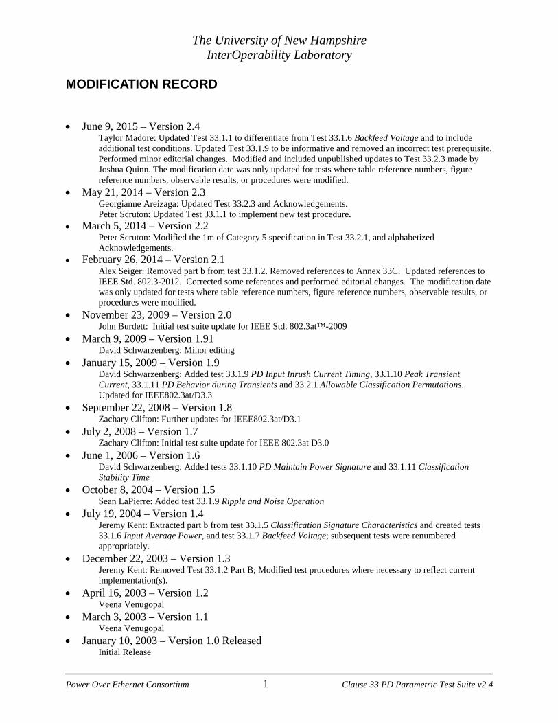
MODIFICATION RECORD • June 9, 2015 – Version 2.4
Taylor Madore: Updated Test 33.1.1 to differentiate from Test 33.1.6 Backfeed Voltage and to include additional test conditions. Updated Test 33.1.9 to be informative and removed an incorrect test prerequisite. Performed minor editorial changes. Modified and included unpublished updates to Test 33.2.3 made by Joshua Quinn. The modification date was only updated for tests where table reference numbers, figure reference numbers, observable results, or procedures were modified.
• May 21, 2014 – Version 2.3 Georgianne Areizaga: Updated Test 33.2.3 and Acknowledgements. Peter Scruton: Updated Test 33.1.1 to implement new test procedure.
• March 5, 2014 – Version 2.2 Peter Scruton: Modified the 1m of Category 5 specification in Test 33.2.1, and alphabetized Acknowledgements.
• February 26, 2014 – Version 2.1 Alex Seiger: Removed part b from test 33.1.2. Removed references to Annex 33C. Updated references to IEEE Std. 802.3-2012. Corrected some references and performed editorial changes. The modification date was only updated for tests where table reference numbers, figure reference numbers, observable results, or procedures were modified.
• November 23, 2009 – Version 2.0 John Burdett: Initial test suite update for IEEE Std. 802.3at™-2009 • March 9, 2009 – Version 1.91
David Schwarzenberg: Minor editing • January 15, 2009 – Version 1.9
David Schwarzenberg: Added test 33.1.9 PD Input Inrush Current Timing, 33.1.10 Peak Transient Current, 33.1.11 PD Behavior during Transients and 33.2.1 Allowable Classification Permutations. Updated for IEEE802.3at/D3.3
• September 22, 2008 – Version 1.8 Zachary Clifton: Further updates for IEEE802.3at/D3.1 • July 2, 2008 – Version 1.7 Zachary Clifton: Initial test suite update for IEEE 802.3at D3.0 • June 1, 2006 – Version 1.6
David Schwarzenberg: Added tests 33.1.10 PD Maintain Power Signature and 33.1.11 Classification Stability Time
• October 8, 2004 – Version 1.5 Sean LaPierre: Added test 33.1.9 Ripple and Noise Operation
• July 19, 2004 – Version 1.4 Jeremy Kent: Extracted part b from test 33.1.5 Classification Signature Characteristics and created tests 33.1.6 Input Average Power, and test 33.1.7 Backfeed Voltage; subsequent tests were renumbered appropriately.
• December 22, 2003 – Version 1.3 Jeremy Kent: Removed Test 33.1.2 Part B; Modified test procedures where necessary to reflect current implementation(s).
• April 16, 2003 – Version 1.2 Veena Venugopal
• March 3, 2003 – Version 1.1 Veena Venugopal
• January 10, 2003 – Version 1.0 Released Initial Release

The University of New Hampshire InterOperability Laboratory
Power Over Ethernet Consortium 2 Clause 33 PD Parametric Test Suite v2.4
ACKNOWLEDGEMENTS The University of New Hampshire would like to acknowledge the efforts of the following individuals in the development of this test suite. Georiganne Areizaga University of New Hampshire Nathan Bourgoine University of New Hampshire John Burdett University of New Hampshire Zachary Clifton University of New Hampshire Jeremy Kent University of New Hampshire Jeff Lapak University of New Hampshire Sean LaPierre University of New Hampshire Taylor Madore University of New Hampshire Gerard Nadeau University of New Hampshire Joshua Quinn University of New Hampshire Amy Schwarzenberg University of New Hampshire David Schwarzenberg University of New Hampshire Peter Scruton University of New Hampshire Alexander Seiger University of New Hampshire Veena Venugopal University of New Hampshire

The University of New Hampshire InterOperability Laboratory
Power Over Ethernet Consortium 3 Clause 33 PD Parametric Test Suite v2.4
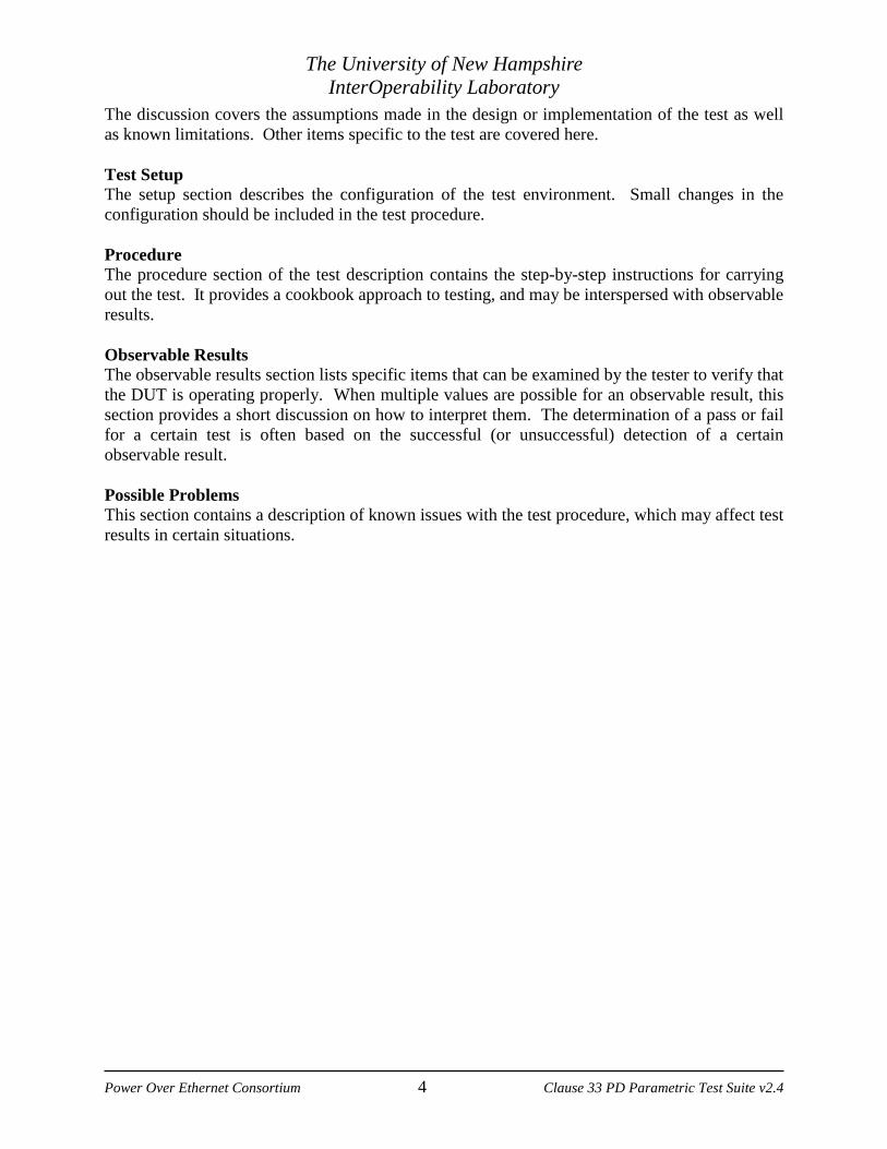
INTRODUCTION Overview The University of New Hampshire’s InterOperability Laboratory (IOL) is an institution designed to improve the interoperability of standards based products by providing an environment where a product can be tested against other implementations of a standard. This suite of tests has been developed to help implementers evaluate the functionality of their IEEE Std. 802.3™-2012 based products. The tests do not determine if a product conforms to the IEEE Std. 802.3™-2012 standard, not definitively. Successful completion of all tests contained in this suite does not guarantee that the tested device will operate with other Power over Ethernet capable devices. However, combined with satisfactory operation in the IOL’s interoperability test bed, these tests provide a reasonable level of confidence that the Device Under Test (DUT) will function well in many Power over Ethernet environments. Organization of Tests The tests contained in this document are organized to simplify the identification of information related to a test and to facilitate in the actual testing process. Each test contains an identification section that describes the test and provides cross-reference information. The discussion section covers background information and specifies why the test is to be performed. Tests are grouped in order to reduce setup time in the lab environment. Each test contains the following information: Test Number The Test Number associated with each test follows a simple grouping structure. Listed first is the Test Group Number followed by the test's number within the group. This allows for the addition of future tests to the appropriate groups of the test suite without requiring the renumbering of the subsequent tests. Purpose The purpose is a brief statement outlining what the test attempts to achieve. The test is written at the functional level. References The references section lists cross-references to the IEEE Std. 802.3™-2012 standard and other documentation that might be helpful in understanding and evaluating the test and results. Resource Requirements The requirements section specifies the hardware, and test equipment that will be needed to perform the test. The items contained in this section are special test devices or other facilities, which may not be available on all devices. Last Modification This specifies the date of the last modification to this test. Discussion
The University of New Hampshire InterOperability Laboratory
Power Over Ethernet Consortium 4 Clause 33 PD Parametric Test Suite v2.4
The discussion covers the assumptions made in the design or implementation of the test as well as known limitations. Other items specific to the test are covered here. Test Setup The setup section describes the configuration of the test environment. Small changes in the configuration should be included in the test procedure. Procedure The procedure section of the test description contains the step-by-step instructions for carrying out the test. It provides a cookbook approach to testing, and may be interspersed with observable results. Observable Results The observable results section lists specific items that can be examined by the tester to verify that the DUT is operating properly. When multiple values are possible for an observable result, this section provides a short discussion on how to interpret them. The determination of a pass or fail for a certain test is often based on the successful (or unsuccessful) detection of a certain observable result. Possible Problems This section contains a description of known issues with the test procedure, which may affect test results in certain situations.

The University of New Hampshire InterOperability Laboratory
Power Over Ethernet Consortium 5 Clause 33 PD Parametric Test Suite v2.4
TABLE OF CONTENTS MODIFICATION RECORD .......................................................................................................... 1
ACKNOWLEDGEMENTS ............................................................................................................ 2
TABLE OF CONTENTS ................................................................................................................ 5
GROUP 1: PD ELECTRICAL CHARACTERISTICS .................................................................. 6
33.1.1: SOURCE POWER ............................................................................................................... 7 33.1.2: VALID PD PINOUT ........................................................................................................... 8 33.1.3: VALID DETECTION SIGNATURE CHARACTERISTICS .......................................................... 9 33.1.4: NON-VALID DETECTION SIGNATURE CHARACTERISTICS ............................................... 11 33.1.5: INPUT AVERAGE POWER ................................................................................................ 12 33.1.6: BACKFEED VOLTAGE ..................................................................................................... 13 33.1.7: PD INPUT VOLTAGE ....................................................................................................... 14 33.1.8: PD MAINTAIN POWER SIGNATURE ................................................................................ 15 33.1.9: PD INPUT INRUSH CURRENT TIMING (INFORMATIVE) .................................................... 16 33.1.10: PEAK TRANSIENT CURRENT ......................................................................................... 17 33.1.11: PD BEHAVIOR DURING TRANSIENTS ........................................................................... 19
GROUP 2: PD CLASSIFICATION TESTS ................................................................................ 20
33.2.1: ALLOWED CLASSIFICATION PERMUTATIONS .................................................................. 21 33.2.2: SINGLE EVENT PHYSICAL LAYER CLASSIFICATION ........................................................ 22 33.2.3: TWO EVENT PHYSICAL LAYER CLASSIFICATION ............................................................ 23 33.2.4: CLASSIFICATION STABILITY TIME .................................................................................. 25
The University of New Hampshire InterOperability Laboratory
Power Over Ethernet Consortium 6 Clause 33 PD Parametric Test Suite v2.4
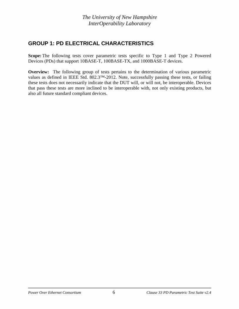
GROUP 1: PD ELECTRICAL CHARACTERISTICS Scope: The following tests cover parametric tests specific to Type 1 and Type 2 Powered Devices (PDs) that support 10BASE-T, 100BASE-TX, and 1000BASE-T devices. Overview: The following group of tests pertains to the determination of various parametric values as defined in IEEE Std. 802.3™-2012. Note, successfully passing these tests, or failing these tests does not necessarily indicate that the DUT will, or will not, be interoperable. Devices that pass these tests are more inclined to be interoperable with, not only existing products, but also all future standard compliant devices.

The University of New Hampshire InterOperability Laboratory
Power Over Ethernet Consortium 7 Clause 33 PD Parametric Test Suite v2.4
33.1.1: Source Power Purpose: To verify that DUT does not source power on its power interface (PI). Reference:
[1] IEEE Std 802.3-2012: Subclause 33.3.1, Table 33-13, Item PD3
Resource Requirements: • Voltmeter • Ammeter • Power Supply
Last Modification: June 5, 2015 Discussion: A PD should not be capable of sourcing power on either of the two sets of PI conductors at any time. Test Setup: Connect the Mode A positive Vport pins of the DUT to the positive terminal of the voltmeter, and the negative Vport pins to the negative terminal of the voltmeter. If the DUT has an alternate, non-PoE power source, use it to power the DUT. Procedure:
1. Measure VPort at the PI of the DUT using a voltmeter. 2. Verify that there is no power present at the PI. 3. Repeat steps 1 and 2 for Mode B.
Observable Results:
a. The DUT should not source power onto the PI at any time. Possible Problem: None

The University of New Hampshire InterOperability Laboratory
Power Over Ethernet Consortium 8 Clause 33 PD Parametric Test Suite v2.4
33.1.2: Valid PD Pinout Purpose: To verify that the DUT is insensitive to the polarity of the power supply and is able to
operate in either Mode A or Mode B. Reference:
[1] IEEE Std 802.3-2012: Subclause 33.3.1, Table 33-13 Resource Requirements
• Power Supply Last Modification: February 27, 2014 Discussion: After detection and optional classification, a PSE may supply power on either set of the four wire pairs, hence the PD must support drawing its power from both Mode A and Mode B regardless of the polarity of the power supply.
Test Setup: Connect the Mode A positive Vport pins of the DUT to the positive terminal of the power supply, and the negative Vport pins to the negative terminal of the power supply. Procedure:
1. Apply power to the PI using Alternative A MDI. 2. Observe the operational status of the DUT. 3. Repeat steps 1 and 2, however, applying power on Mode A MDI-X, Mode B MDI, and
Mode B MDI-X. Observable Results:
a. In all cases the DUT should accept the applied power and become operational once the requested power has been supplied.
Possible Problem: None

The University of New Hampshire InterOperability Laboratory
Power Over Ethernet Consortium 9 Clause 33 PD Parametric Test Suite v2.4
33.1.3: Valid Detection Signature Characteristics Purpose: To verify that the DUT presents a valid detection signature while it is requesting
power on the power interface (PI). References:
[1] IEEE Std 802.3-2012: Section 33.3.4, Table 33-14, Figure 33-17 Resource Requirements:
• Power Supply • Voltage meter • Ammeter
Last Modification: February 27, 2014 Discussion: If a PD will accept power, but is not powered, via the PI then it should present a valid detection signature at the PI between the positive and negative VPort pins for both pinout Modes such that the attached PSE will properly detect the PD’s request for power. The standard defines the signature to be comprised of five characteristics: a valid resistance, capacitance, and inductance; and either a voltage offset or a current offset. The voltage offset limit was specified to allow for the inherent voltage offset for two series diode drops. Similarly, the current limit allows for internal FET leakage. Given the minimum and maximum limits on the defined resistive slope, there are no minimum bounds for the offset components as a maximum current implies a minimum voltage, and vice versa. Figure 33-17, reproduced below, illustrates the signature resistance and voltage offsets.
Test Setup: Connect the Mode A positive Vport pins of the DUT to the positive terminal of the power supply, and the negative Vport pins to the negative terminal of the power supply.

The University of New Hampshire InterOperability Laboratory
Power Over Ethernet Consortium 10 Clause 33 PD Parametric Test Suite v2.4
Procedure:
1. Limit the power supply current between 4 to 5 mA. 2. Applying voltage using Alternative A, vary the power supply voltage, VN, from 0.0 V to
3.0 V in steps of 50 mV and measure the corresponding current, IN, drawn by the DUT. 3. Vary the power supply voltage, VN, from 3.2 V to 10.2 V in steps of 200 mV and measure
the corresponding current, IN, drawn by the DUT. 4. Calculate RsigN using a 1 V chord between measurement points. 5. Determine either the voltage offset or the current offset by calculating the intersection of
the line between the (VN, IN) and (VN+1, IN+1) data points and V/I axis. 6. Repeat steps 1-5, however, connect the DUT to accept power on Mode B.
Observable Results:
a. In step 4 the observed signature resistance should be between 23.75 KΩ and 26.3KΩ (inclusive).
b. In step 5 the DUT should have either a voltage offset less than or equal to 1.9 V, or a current offset less than 12 µA.
Possible Problems: None

The University of New Hampshire InterOperability Laboratory
Power Over Ethernet Consortium 11 Clause 33 PD Parametric Test Suite v2.4
33.1.4: Non-Valid Detection Signature Characteristics Purpose: To verify that the DUT presents a non-valid detection signature while it is not requesting power, or once powered, at the power interface (PI) of the non-powered pairs. Reference:
[1]IEEE Std 802.3-2012: Subclause 33.3.4, Table 33-15 Resource Requirements:
• Power Supply • Voltage meter • Ammeter
Last Modification: November 23, 2009 Discussion: There are two cases when a PD should present a non-valid detection signature when attached to the PSE via the PI. The first case is while a PD is in a state where it will not accept power via the PI. The second case occurs once a PD becomes powered via the PI, and it must present a non-valid detection signature on the set of pairs from which it is not drawing power. Test Setup: Connect the Mode A positive Vport pins of the DUT to the positive terminal of the power supply, and the negative Vport pins to the negative terminal of the power supply. Procedure:
1. Limit the power supply current between 4 to 5 mA. 2. Apply power onto the PI using Alternative A, and confirm the DUT is drawing power via
the PI. 3. Applying voltage to the non-powered pairs, vary the power supply voltage, VN, from 0.0
V to 3.0 V in steps of 50 mV and measure the corresponding current, IN, drawn by the DUT.
4. Vary the power supply voltage, VN, from 3.2 V to 10.2 V in steps of 200 mV and measure the corresponding current, IN, drawn by the DUT.
5. Calculate RsigN using a 1 V chord between measurement points. 6. Repeat steps 1-5; however, connect the DUT to accept power on Mode B.
Observable Results:
a. In step 5 verify that RsigN < 12 KΩ or RsigN > 45 KΩ. Possible Problems: None

The University of New Hampshire InterOperability Laboratory
Power Over Ethernet Consortium 12 Clause 33 PD Parametric Test Suite v2.4
33.1.5: Input Average Power Purpose: To verify that the DUT will turn on once power has been applied to the power interface (PI), will remain on over the entire port voltage range, and turn off once power is removed. Reference:
[1] IEEE Std 802.3-2012: Subclause 33.3.7.2, Table 33-18 Resource Requirements:
• Power Supply • Oscilloscope • Current Probe
Last Modification: February 27, 2014 Discussion: For a PD that supports classification, the maximum power that the PD may draw across all input voltages and operational modes is governed by the limits specified in table 33-18. This value is known as PCLASS_PD.
Derived From Item 4 of Table 33-18
Class Maximum
power available to PD
PD Type
0 13.0 Watts 1 1 3.84 Watts 1 2 6.49 Watts 1 3 13.0 Watts 1 4 25.5 Watts 2
Test Setup: Connect the Mode A positive Vport pins of the DUT to the positive terminal of the power supply, and the negative Vport pins to the negative terminal of the power supply. Procedure:
1. If possible, configure the DUT for desired Class operation. 2. Apply a port voltage of 44 V onto the PI using Alternative A. 3. Measure the current drawn by the DUT and calculate the input power averaged over a 1
second period. 4. Repeat steps 1-2, however, apply power using Alternative B and a port voltage of 57 V. 5. Repeat steps 1-3 for all supported classes.
Observable Results: a. The maximum power drawn by the DUT for each supported class should be below the
maximum value specified in table 33-18. Possible Problems: None.
The University of New Hampshire InterOperability Laboratory
Power Over Ethernet Consortium 13 Clause 33 PD Parametric Test Suite v2.4
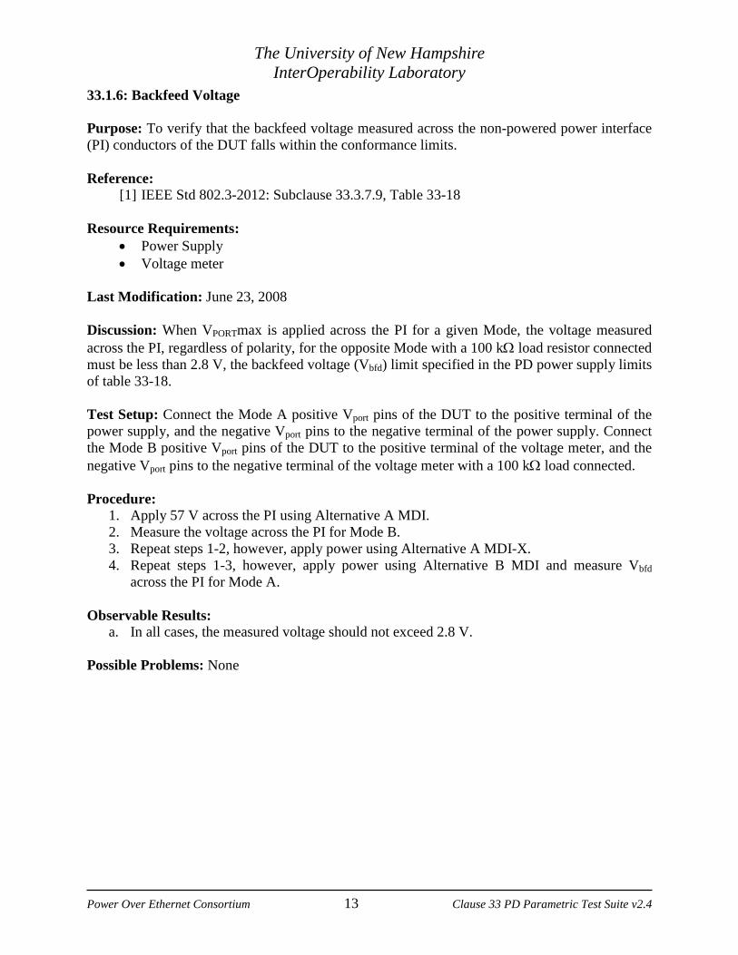
33.1.6: Backfeed Voltage Purpose: To verify that the backfeed voltage measured across the non-powered power interface (PI) conductors of the DUT falls within the conformance limits. Reference:
[1] IEEE Std 802.3-2012: Subclause 33.3.7.9, Table 33-18 Resource Requirements:
• Power Supply • Voltage meter
Last Modification: June 23, 2008 Discussion: When VPORTmax is applied across the PI for a given Mode, the voltage measured across the PI, regardless of polarity, for the opposite Mode with a 100 kΩ load resistor connected must be less than 2.8 V, the backfeed voltage (Vbfd) limit specified in the PD power supply limits of table 33-18. Test Setup: Connect the Mode A positive Vport pins of the DUT to the positive terminal of the power supply, and the negative Vport pins to the negative terminal of the power supply. Connect the Mode B positive Vport pins of the DUT to the positive terminal of the voltage meter, and the negative Vport pins to the negative terminal of the voltage meter with a 100 kΩ load connected. Procedure:
1. Apply 57 V across the PI using Alternative A MDI. 2. Measure the voltage across the PI for Mode B. 3. Repeat steps 1-2, however, apply power using Alternative A MDI-X. 4. Repeat steps 1-3, however, apply power using Alternative B MDI and measure Vbfd
across the PI for Mode A. Observable Results:
a. In all cases, the measured voltage should not exceed 2.8 V. Possible Problems: None
The University of New Hampshire InterOperability Laboratory
Power Over Ethernet Consortium 14 Clause 33 PD Parametric Test Suite v2.4
33.1.7: PD Input Voltage Purpose: To verify that the DUT will turn on once power has been applied to the power interface (PI), will remain on over the entire port voltage range, and turn off once power is removed. Reference:
[1] IEEE Std 802.3-2012: Subclause 33.3.7.1, Table 33-18 Resource Requirements:
• Power Supply • Current meter
Last Modification: November 23, 2009 Discussion: After startup, a PD is required to turn on its power supply before the input voltage (Vport) level reaches 42 V. Once turned on, the power supply then must remain on over the entire range of Vport, which is specified from 37 V to 57 V for a Type 1 PD and 42.5V to 57V for a Type 2 PD, as the attached PSE may vary the applied voltage on the PI over this range at any time. If the minimum value of Vport is not maintained by the PSE, the PD must turn off before the input voltage level reaches 30 V. Test Setup: Connect the Mode A positive Vport pins of the DUT to the positive terminal of the power supply, and the negative Vport pins to the negative terminal of the power supply. Procedure:
1. Apply 42 V across the PI. 2. Observe the operational status of the DUT. 3. Repeat steps 1 and 2, however, increment the applied voltage by 1 V until the DUT has
become fully operational. 4. Once operational, increase the applied voltage to 57 V in 1 V increments, and then
decrease the voltage to 49 V. 5. Observe the operational status of the DUT. 6. Decrease the applied voltage by 1 V. 7. Observe the status of the DUT. 8. Repeat steps 6 and 7 until the DUT turns off. 9. Repeat steps 1-8, however, connect the DUT to accept power on Mode B.
Observable Results:
a. The DUT should become fully operational at a port voltage less than 42 V. b. Once the DUT has turned on, it should remain operational for VPORT between 37 V and
57 V for a Type 1 PD and 42.5V to 57V for a Type 2 PD. c. The DUT should turn off at a port voltage greater than 30V and less than 37 V for a Type
1 PD. A Type 2 PD should turn off at a port voltage greater than 30V and less than 41 V. Possible Problems: None
The University of New Hampshire InterOperability Laboratory
Power Over Ethernet Consortium 15 Clause 33 PD Parametric Test Suite v2.4
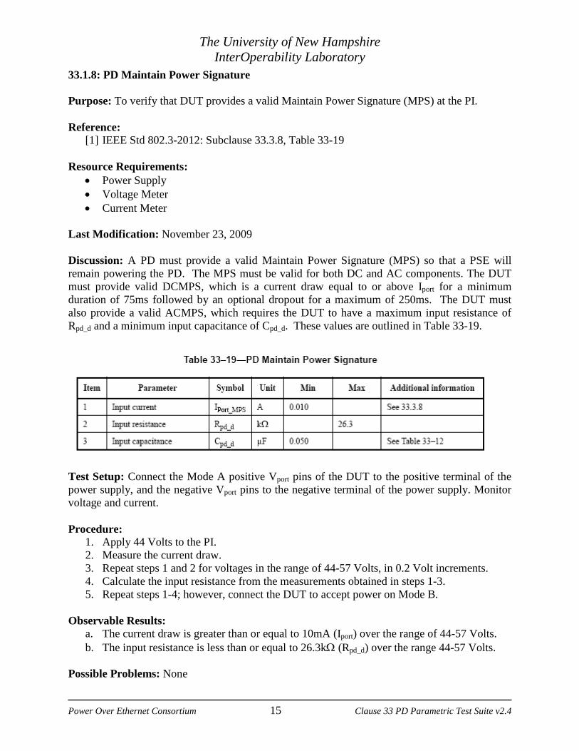
33.1.8: PD Maintain Power Signature Purpose: To verify that DUT provides a valid Maintain Power Signature (MPS) at the PI. Reference:
[1] IEEE Std 802.3-2012: Subclause 33.3.8, Table 33-19 Resource Requirements:
• Power Supply • Voltage Meter • Current Meter
Last Modification: November 23, 2009 Discussion: A PD must provide a valid Maintain Power Signature (MPS) so that a PSE will remain powering the PD. The MPS must be valid for both DC and AC components. The DUT must provide valid DCMPS, which is a current draw equal to or above Iport for a minimum duration of 75ms followed by an optional dropout for a maximum of 250ms. The DUT must also provide a valid ACMPS, which requires the DUT to have a maximum input resistance of Rpd_d and a minimum input capacitance of Cpd_d. These values are outlined in Table 33-19.
Test Setup: Connect the Mode A positive Vport pins of the DUT to the positive terminal of the power supply, and the negative Vport pins to the negative terminal of the power supply. Monitor voltage and current. Procedure:
1. Apply 44 Volts to the PI. 2. Measure the current draw. 3. Repeat steps 1 and 2 for voltages in the range of 44-57 Volts, in 0.2 Volt increments. 4. Calculate the input resistance from the measurements obtained in steps 1-3. 5. Repeat steps 1-4; however, connect the DUT to accept power on Mode B.
Observable Results:
a. The current draw is greater than or equal to 10mA (Iport) over the range of 44-57 Volts. b. The input resistance is less than or equal to 26.3kΩ (Rpd_d) over the range 44-57 Volts.
Possible Problems: None
The University of New Hampshire InterOperability Laboratory
Power Over Ethernet Consortium 16 Clause 33 PD Parametric Test Suite v2.4
33.1.9: PD Input Inrush Current Timing (Informative) Purpose: To verify that the PD input inrush current timing is within conformant limits. Reference:
[1] IEEE Std 802.3-2012: Subclause 33.3.7.3, Table 33-11 Resource Requirements:
• Power Supply • Oscilloscope
Last Modification: June 5, 2015 Discussion: This test measures the length of time the PD’s input inrush current exists. It is defined as the time from the application of VPORT to the time when CPORT is charged to 99% of its final value. Test Setup: Using the PD test jig, connect the Mode A positive Vport pins of the DUT to the positive terminal of the power supply, and the negative Vport pins to the negative terminal of the power supply. Procedure:
1. Apply a port voltage of 44 V onto the PI using Alternative A. 2. Using an oscilloscope, measure TINRUSH. 3. Repeat steps 1-2, however, apply power using Alternative B. 4. Repeat steps 1-3 with a port voltage of 57 V.
Observable Results: a. In step 2 and 3, TINRUSH should be less than 50 ms.
Possible Problems: None

The University of New Hampshire InterOperability Laboratory
Power Over Ethernet Consortium 17 Clause 33 PD Parametric Test Suite v2.4
33.1.10: Peak Transient Current Purpose: To verify that the PD peak current transients and levels are within conformant limits. Reference:
[1] IEEE Std 802.3-2012: Subclause 33.3.7.5, Figure 33-18, Table 33-18 Resource Requirements:
• Power Supply • Oscilloscope • Current Probe
Last Modification: February 27, 2014 Discussion: With a static input voltage at the PI, after inrush, the PD should limit the transient current draw. The transients should not exceed 4.7mA/µs for either polarity. These transients should not exceed PPeak_PD and also must not exceed PClass_PD for longer than Tcutmin per figure 33-18.
Test Setup: Using the PD test jig, connect the Mode A positive Vport pins of the DUT to the positive terminal of the power supply, and the negative Vport pins to the negative terminal of the power supply. Monitor the current draw with the current probe. Procedure:
1. Apply a valid static input voltage at the PI of the PD. 2. Attempt to get the PD to rapidly change its current draw. 3. Monitor the current draw using the current probe.
The University of New Hampshire InterOperability Laboratory
Power Over Ethernet Consortium 18 Clause 33 PD Parametric Test Suite v2.4
Observable Results: a. In step 3 the transient current drawn should not exceed 4.7mA/μs. b. In step 2 the current draw should be less than the PD static operating mask as defined in
Figure 33-18. Possible Problems: It may be difficult to get a PD to rapidly change current draw, especially for consumer end products.
The University of New Hampshire InterOperability Laboratory
Power Over Ethernet Consortium 19 Clause 33 PD Parametric Test Suite v2.4
33.1.11: PD Behavior During Transients Purpose: To verify that the PD input current stays within the conformant regions for voltage transients on the PD PI. Reference:
[2] IEEE Std 802.3-2012: Subclause 33.3.7.6, Figure 33-18, Table 33-18, Equation 33-13 Resource Requirements:
• Power Supply • Oscilloscope • Current Probe
Last Modification: February 27, 2014 Discussion: The PD current draw should be within the specified ranges for input voltage transients at the PI. This test is only applicable if the input capacitance is greater than 180µF. Test Setup: Using the PD test jig, connect the Mode A positive Vport pins of the DUT to the positive terminal of the power supply, and the negative Vport pins to the negative terminal of the power supply. Monitor the voltage and the current with the oscilloscope at the PI. Procedure: Case 1: Type 1 PD
1. Apply a port voltage of 44 V onto the PI using Alternative A. 2. Ramp this to 57V at a rate of 2250V/s 3. Measure the PD input current. 4. Repeat steps 1-3 for Alternative B
Case 2: Type 2 PD 5. Apply a port voltage of 50 V onto the PI using Alternative A. 6. Drive the PD PI voltage to 52.5V at greater than 3.5V/µs. 7. Measure the PD input current spike. 8. Return the port voltage to 50V 9. Ramp this to 56V at a rate of 2250V/s 10. Measure the PD input current. 11. Repeat steps 5-10 for Alternative B.
Observable Results: a. In step 3, the PD input current shall not exceed the PD upperbound template per Figure
33-19. b. In step 7, the PD input current spike shall not exceed 2.5A and should settle below the
PD upperbound template within 4ms. c. In step 10, the PD shall not exceed the PD upperbound template.
Possible Problems: Only applicable for PDs with an input capacitance greater than180µF.

The University of New Hampshire InterOperability Laboratory
Power Over Ethernet Consortium 20 Clause 33 PD Parametric Test Suite v2.4
GROUP 2: PD CLASSIFICATION TESTS Scope: The following tests cover classification tests specific to Type 1 and Type 2 Powered Devices (PDs) that support 10BASE-T, 100BASE-TX, and 1000BASE-T devices. Overview: The following group of tests pertains to the determination of various parametric values as defined in IEEE Std 802.3at™-2012. Note, successfully passing these tests, or failing these tests does not necessarily indicate that the DUT will, or will not, be interoperable. Devices that pass these tests are more inclined to be interoperable with, not only existing products, but also all future standard compliant devices.

The University of New Hampshire InterOperability Laboratory
Power Over Ethernet Consortium 21 Clause 33 PD Parametric Test Suite v2.4
33.2.1: Allowed Classification Permutations Purpose: To verify whether the PD fits a valid classification permutation. References: [1] IEEE Std 802.3-2012: Subclause 33.2.8, Table 33–8 Resource Requirements:
• SmartBits • Current Meter • Voltage Meter • Power Supply
Last Modification: March 5, 2014 Discussion: A PD shall meet one of the allowable classification permutations listed in Table 33–8.
Table 33-8
Test Setup: The DUT is connected to the PD simulator with a short (less than 1m) length of Category 5, or better, cable. The oscilloscope is connected to the PD simulator at the PI. Procedure:
1. Determine the DUTs Class Current Draw 2. Monitor for Data Link Layer classification for more than 5 minutes.
Observable Results:
• The DUT should be an allowable type as specified by table 33-8 Possible Problems: None.

The University of New Hampshire InterOperability Laboratory
Power Over Ethernet Consortium 22 Clause 33 PD Parametric Test Suite v2.4
33.2.2: Single Event Physical Layer Classification Purpose: To verify that a PD returns the correct classification current draw. Reference:
[1] IEEE Std 802.3-2012: Subclause 33.3.5.1, Table 33-16 Resource Requirements:
• Power Supply • Voltage Meter • Ammeter
Last Modification: November 23, 2009 Discussion: The purpose of PD classification is to provide the PSE information about the maximum power that the PD will draw across all input voltages and operational modes. A PD should present one and only one classification signature during classification. By default, a type 1 PD is Class 0; however, to improve power management for the PSE, a PD may provide a signature for Class 1 to 3, which are outlined in table 33-16. Type 2 PDs implementing 1 event classification shall respond with a Class 4 signature.
Table 33-16 - Classification signature, measured at PD input connector
Parameter Conditions Minimum Maximum Unit Current for Class 0 14.5 V to 20.5 V 0 4.00 mA Current for Class 1 14.5 V to 20.5 V 9.00 12.0 mA Current for Class 2 14.5 V to 20.5 V 17.0 20.0 mA Current for Class 3 14.5 V to 20.5 V 26.0 30.0 mA Current for Class 4 14.5 V to 20.5 V 36.0 44.0 mA
Test Setup: Connect the Mode A positive Vport pins of the DUT to the positive terminal of the power supply, and the negative Vport pins to the negative terminal of the power supply. Procedure:
1. Apply power onto the PI using Alternative A, varying the power supply voltage from 12.5V to 22.5V.
2. Measure the corresponding current drawn by the DUT. 3. Repeat steps 1-2, however, connect the DUT to accept power on Mode B.
Observable Results:
a. In step 2 the current drawn by the DUT for each supported class should be within the range (inclusive) specified in table 33-16.
b. The DUT should only present one classification signature during classification. Possible Problems: None.

The University of New Hampshire InterOperability Laboratory
Power Over Ethernet Consortium 23 Clause 33 PD Parametric Test Suite v2.4
33.2.3: Two Event Physical Layer Classification Purpose: To verify that a Type-2 PD correctly implements two-event physical layer classification. Reference:
[1] IEEE Std 802.3-2012: Subclause 33.3.5.2, Table 33-15, Table 33-17, Table 33-18, Figure 33-16
Resource Requirements:
• Power Supply • Arbitrary Waveform Generator • DMM, DSO, Current Probe
Last Modification: June 5, 2015 Discussion: A Type-2 PD’s behavior must conform to the state diagram defined in Figure 33-16 The PD must present valid current draws at all states within the state diagram. The PD shall return a Class 4 classification signature in accordance with the maximum power draw, PClass_PD, as well as conform to electrical requirements as specified by Table 33–18. This test applies the appropriate voltages and checks DUT behavior to determine whether or not the DUT steps through the state diagram correctly. Test Setup: Connect the power supply to the class pulse circuit, which generates the class pulses with an AWG. Attach the PI of the DUT to the class pulse circuit. Monitor PI voltage and current with the DSO. Procedure:
1. Apply power consistent with detection timing and amplitude to the PI on Mode A. 2. Apply a 2-event classification pulse with timing and amplitude that are close to the
minimum timing and minimum amplitude parameters. 3. Measure current for all stages of 2-event classification. 4. Apply power to the PI on Mode A. 5. Check for external indication that a 2-event class pulse was received. 6. Repeat steps 1-5 for different combinations of timing and amplitude that are close to the
minimum and maximum timing and amplitude parameters. 7. Repeat steps 1-6 for Mode B. 8. Measure VRESET by repeating steps 1-5 and setting VMARK2 to a voltage below 2.8 volts
and increasing it until the device exhibits a 2 event response. 9. Repeat steps 1-5, but in step two apply a voltage at or slightly below the VRESET value
measured in step 8 for VMARK1.
Observable Results: a. The DUT should successfully transition throughout the state diagram. b. In step 5 for conformant 2-event pulses, the DUT should indicate that a 2-event class
pulse was received, either through external indication or through a power draw exceeding the maximum Type 1 power in step 4 (not to exceed the maximum Type 2 power draw).

The University of New Hampshire InterOperability Laboratory
Power Over Ethernet Consortium 24 Clause 33 PD Parametric Test Suite v2.4
c. In step 3, classification current draw for both pulses should be within 36 and 44mA for a Type 2 PD. For a Type 1 PD this shall indicate a valid current draw based on the PD’s Class (0-3) for both pulses.
d. In step 3, IMark should be within 0.25-4.00mA. e. In step 3, the DUT should present an invalid detection signature during VMARK1 and
VMARK2. Unless the input capacitance is greater than 10uF, the maximum resistance detected should be 12KΩ when VMARK1 and VMARK2 are varied between 6.9V and 10.1V.
f. In step 8, determine whether the application of VRESET successfully restarts the classification process. If external indication of 2-event class pulse is available, the DUT should not indicate that it has received a 2-event class pulse after VRESET. Check the maximum power draw to ensure that the PD does not exceed maximum power for a Type 1 device.
Possible Problems: This test is not applicable to Type 1 PDs that do not implement 2-event physical layer classification.

The University of New Hampshire InterOperability Laboratory
Power Over Ethernet Consortium 25 Clause 33 PD Parametric Test Suite v2.4
33.2.4: Classification Stability Time Purpose: To verify that classification current draw of the DUT is valid within Tclass. Reference:
[1] IEEE Std 802.3-2012: Subclause 33.3.7.8, Table 33-16, Table 33-17, Table 33-18 Resource Requirements:
• Power Supply • Class Pulse Circuit • DSO
Last Modification: November 23, 2009 Discussion: When the PSE performs a class event, the PI of a PD is probed with a voltage in the range of 14.5V to 20.5V. The classification level of the PD is determined by observing the current draw. The classification current draw of the PD must be valid before 5ms (Tclass), so that the PSE will properly detect the PD. The classification currents are outlined in Table 33-16. Test Setup: Connect the power supply to the class pulse circuit. Attach the PI of the DUT to the class pulse circuit. Monitor PI voltage and current with the DSO. Procedure:
1. Apply a class pulse at the minimum condition of 14.5 Volts. 2. Measure the delay between the rising edge of the class pulse and the point when the valid
classification current level is reached. 3. Observe the current draw after Tclass. 4. Repeat steps 1-3 with the maximum condition of 20.5 Volts. 5. Repeat steps 1-4; however, connect the DUT to accept power on Mode B.
Observable Results:
a. The classification current draw is valid within 5ms (Tclass). b. The classification current draw is within the valid range for all times after Tclass.
Possible Problems: None.