Automotive Ethernet AVB Functional and Interoperability ...€¦ · Automotive Ethernet AVB...
53
Automotive Ethernet AVB Functional and Interoperability Specification Revision 1.4 12 May 2015 Authors: Gordon Bechtel, Ben Gale, Max Kicherer, Dave Olsen All members of the AVnu Automotive Technical Working Group contributed to this document
Transcript of Automotive Ethernet AVB Functional and Interoperability ...€¦ · Automotive Ethernet AVB...
1
2
3
Automotive Ethernet AVB 4
Functional and Interoperability 5
Specification 6
7
8
Revision 1.4 9
10
12 May 2015 11
12
Authors: 13
Gordon Bechtel, Ben Gale, Max Kicherer, Dave Olsen 14
15
All members of the AVnu Automotive Technical Working 16
Group contributed to this document 17 18
19 20
21
Automotive Ethernet AVB Functional and Interoperability Specification
Revision 1.4 - Public • 12 May 2015 Section 0 • Page 2
Table of Contents 22
1 Introduction ................................................................................................................................ 6 23
2 Glossary ...................................................................................................................................... 8 24
3 References ................................................................................................................................ 10 25
4 Scope ........................................................................................................................................ 11 26
5 Network and Device Startup ...................................................................................................... 13 27
5.1 Ethernet Interface Configuration ........................................................................................................................................ 13 28
5.2 States and Events ....................................................................................................................................................................... 13 29
5.3 Test Mode and Status Message Structure - Endstations ............................................................................................ 15 30
5.3.1 subtype field ................................................................................................................................................................................... 16 31
5.3.2 sv field ................................................................................................................................................................................................ 16 32
5.3.3 version field..................................................................................................................................................................................... 16 33
5.3.4 control_data field ......................................................................................................................................................................... 17 34
5.3.5 status field ....................................................................................................................................................................................... 17 35
5.3.6 control_data_length field.......................................................................................................................................................... 17 36
5.3.7 target_entity_id field................................................................................................................................................................... 17 37
5.3.8 controller_entity_id field ........................................................................................................................................................... 17 38
5.3.9 sequence_id field ........................................................................................................................................................................... 17 39
5.3.10 u field .............................................................................................................................................................................................. 17 40
5.3.11 command_type field ................................................................................................................................................................. 17 41
5.3.12 descriptor_type field ................................................................................................................................................................ 18 42
5.3.13 descriptor_index field .............................................................................................................................................................. 18 43
5.3.14 counters_valid field................................................................................................................................................................... 18 44
5.3.15 counter[0] field (Link_Up count)........................................................................................................................................ 19 45
5.3.16 counter[1] field (Link_Down count) ................................................................................................................................. 19 46
5.3.17 counter[2] field (Frames_Tx count) .................................................................................................................................. 19 47
5.3.18 counter[3] field (Frames_Rx count) .................................................................................................................................. 19 48
5.3.19 counter[4] field (Rx_CRC_Error count) ........................................................................................................................... 19 49
5.3.20 counter[5] field (GPTP_GM_Changed count) ................................................................................................................ 19 50
5.3.21 counter[6] through counter[23] fields ............................................................................................................................ 20 51
5.3.22 counter[24] and counter[25] fields (message_timestamp) ................................................................................... 20 52
5.3.23 counter[26], octet 0 field (station_state field) ............................................................................................................. 20 53
5.3.24 counter[26], octet 1-3 field (station_state_specific_data) ...................................................................................... 21 54
5.3.25 counter[27] through counter[31] ...................................................................................................................................... 21 55
5.4 Addressing .................................................................................................................................................................................... 21 56
5.5 Startup Timing ............................................................................................................................................................................ 21 57
6 Generalized Precision Time Protocol (gPTP) ............................................................................... 26 58
6.1 Scope ............................................................................................................................................................................................... 26 59
6.2 gPTP Configuration ................................................................................................................................................................... 26 60
Automotive Ethernet AVB Functional and Interoperability Specification
Revision 1.4 - Public • 12 May 2015 Section 0 • Page 3
6.2.1 Static gPTP Values ....................................................................................................................................................................... 27 61
6.2.1.1 Grandmaster Information and Topology ............................................................................................................................... 27 62
6.2.1.2 asCapable [gPTP 10.2.4.1] ............................................................................................................................................................ 27 63
6.2.1.3 initialLogPdelayReqInterval [gPTP 11.5.2.2] ....................................................................................................................... 27 64
6.2.1.4 initialLogSyncInterval [gPTP 10.2.4.4] ................................................................................................................................... 27 65
6.2.1.5 operLogPdelayReqInterval .......................................................................................................................................................... 27 66
6.2.1.6 operLogSyncInterval ....................................................................................................................................................................... 28 67
6.2.2 Persistent gPTP Values .............................................................................................................................................................. 28 68
6.2.2.1 neighborPropDelay [gPTP 10.2.4.7] ........................................................................................................................................ 28 69
6.2.2.2 rateRatio [gPTP 10.2.2.1.7] .......................................................................................................................................................... 28 70
6.2.2.3 neighborRateRatio [gPTP 10.2.4.6] .......................................................................................................................................... 29 71
6.2.3 Management Updated Values ................................................................................................................................................ 29 72
6.2.3.1 SyncInterval [gPTP, clause 10.2.4.5] ........................................................................................................................................ 29 73
6.2.3.2 pdelayReqInterval ............................................................................................................................................................................ 30 74
6.2.4 gPTP Signaling Message [gPTP 10.5.4] ............................................................................................................................. 30 75
6.2.5 FollowUp TLV’s ............................................................................................................................................................................. 30 76
6.2.6 Required Values for gPTP ........................................................................................................................................................ 30 77
6.3 gPTP Operation ........................................................................................................................................................................... 31 78
6.4 Automotive Network Diagrams ........................................................................................................................................... 33 79
7 Media Formats .......................................................................................................................... 35 80
7.1 AVTP Audio Format (AAF) ..................................................................................................................................................... 35 81
7.2 Compressed Video Formats ................................................................................................................................................... 36 82
7.2.1 H.264 .................................................................................................................................................................................................. 37 83
7.2.2 Motion JPEG (MJPEG) ................................................................................................................................................................. 37 84
7.3 MPEG2-TS Container Format ................................................................................................................................................ 37 85
7.4 Clock Reference Format (CRF) ............................................................................................................................................. 37 86
8 Stream Reservation (SR) Classes ................................................................................................ 38 87
8.1 Stream Reservation Class Requirements ......................................................................................................................... 38 88
8.2 Presentation Time Parameters ............................................................................................................................................ 40 89
8.2.1 Maximum Transit Time ............................................................................................................................................................. 40 90
8.2.2 Maximum Timing Uncertainty .............................................................................................................................................. 42 91
8.3 Stream Reservation Requirements..................................................................................................................................... 43 92
9 Exception Handling .................................................................................................................... 44 93
9.1 AVB Device Failure .................................................................................................................................................................... 44 94
9.2 Ethernet Exceptions.................................................................................................................................................................. 45 95
9.2.1 Link State Events .......................................................................................................................................................................... 45 96
9.2.1.1 Link-Down ........................................................................................................................................................................................... 45 97
9.2.1.2 Link-Up .................................................................................................................................................................................................. 45 98
9.2.2 Data Loss .......................................................................................................................................................................................... 45 99
9.3 IEEE 802.1 AS Exceptions....................................................................................................................................................... 46 100
9.3.1 Loss of Sync Messages ................................................................................................................................................................ 46 101
9.3.2 Non-Continuous Sync Values .................................................................................................................................................. 46 102
Automotive Ethernet AVB Functional and Interoperability Specification
Revision 1.4 - Public • 12 May 2015 Section 0 • Page 4
9.3.3 Pdelay Response Timeout......................................................................................................................................................... 46 103
9.3.4 neighborPropDelay value ........................................................................................................................................................ 47 104
9.4 IEEE 1722 Media Stream Exceptions ................................................................................................................................ 47 105
10 Security ................................................................................................................................... 49 106
11 Content Protection .................................................................................................................. 50 107
12 Network Management ............................................................................................................ 51 108
13 Diagnostic Counters ................................................................................................................. 52 109
13.1 Ethernet Interfaces ................................................................................................................................................................. 52 110
13.2 Ethernet Bridging .................................................................................................................................................................... 52 111
13.3 AVB Protocols ........................................................................................................................................................................... 52 112
13.4 1722 Transport ........................................................................................................................................................................ 53 113
114
Automotive Ethernet AVB Functional and Interoperability Specification
Revision 1.4 - Public • 12 May 2015 Section 0 • Page 5
Revision History 115
Revision Author Date Description
0.1 Gordon Bechtel, Ben
Gale, Max Kicherer,
Dave Olsen and all
members of Automotive
CDS
2014-03-11 Initial release of full document.
0.2 Gordon Bechtel 2014-03-12 Added editorial note indicating direction for resolution
of GM failure in section 9.1.1.
0.3 Gordon Bechtel, Ben
Gale, Max Kicherer,
Dave Olsen
2014-04-30 Updated document to include all comments received
from and discussed with members of the Automotive
CDS working group since release 0.2.
1.0 Gordon Bechtel, Ben
Gale, Dave Olsen
2014-06-24 Updated to include all comments from 0.3 release and
subsequent discussions. Please see the comment
resolution spreadsheet for details.1
1.1 Gordon Bechtel 2014-07-29 Updated to include all comments on the 1.0 ballot and
discussions within the automotive CDS. Please see
comment spreadsheet for details.2
1.2 Gordon Bechtel, Ben
Gale, Dave Olsen
2014-11-03 Updated to include all comments on the V1.1 version
discussed within the Automotive CDS. Please see the
comment matrix for details.3
1.3 Gordon Bechtel 2014-11-24 Updated to include all comments on the V1.2 version
discussed within the Automotive CDS. Please see the
comment matrix for details.3
1.4 Gordon Bechtel 2015-05-12 Updated to include all comments on the V1.3 version
discussed within the Automotive CDS during the
process of review and PICS generation. Please see the
comment matrix for details.4
1 https://groups.avnu.org/wg/AVnu_Technical/document/download/3024 (Formerly: http://members.avnu.org/apps/org/workgroup/technical/download.php/3659/avnuAutomotiveSpecInformalReviewCommentsOnV0_3-collated-2014-06-24.xlsx) 2 https://groups.avnu.org/wg/AVnu_Technical/document/download/3071 (Formerly: http://members.avnu.org/apps/org/workgroup/technical/download.php/3701/avnuAutomotiveSpecInformalReviewCommentsOnV1-STC.xls) 3 https://groups.avnu.org/wg/AVnu_Technical/document/3445. 4 https://groups.avnu.org/wg/AVnu_Technical/document/3474.

Automotive Ethernet AVB Functional and Interoperability Specification
Revision 1.4 - Public • 12 May 2015 Section 1 • Page 6
1 Introduction 1
This document is AVnu’s interoperability and functional specification for automotive Ethernet AVB devices. The 2
document’s primary goal is to provide a baseline specification of Ethernet AVB functionality on automotive AVB 3
devices. The specification has several uses, three of which are key. First, vendors can use this specification to 4
guide their automotive AVB product development. Second, AVnu can use it to develop an effective certification 5
process. Third, and most importantly, automotive OEMs can depend on the specification to provide a foundation 6
for AVB functionality in their automobiles. OEMs can be assured that a device certified to be compliant with this 7
specification would provide baseline AVB functionality, would not require extensive testing on their part, and 8
would thereby allow them the time to focus on other functionality that helps differentiate their final product and 9
enable success in the automotive marketplace. 10
This specification focuses on establishing interoperability between devices at those levels of the communication 11
stack where the devices share functional compatibility. For instance, it’s obvious that a rear-view camera module 12
won’t interwork directly with an audio amplifier, simply because these two devices handle different types of 13
media. However, both of these devices do have AVB functionality. Therefore, it is also true that they can interact 14
on more fundamental levels, such as sharing a common wall clock via gPTP and adhering to the traffic shaping 15
rules of FQTSS. This is what is meant by automotive baseline functionality: The functionality required for 16
interoperability at baseline levels of automotive devices’ communications stacks. 17
Common functionality that all automotive Ethernet-AVB devices need in order to operate in the automotive 18
environment. 19
During its development, this specification has come to be referred to as the AVB “automotive profile.” The focus 20
of this version of the automotive profile is infotainment systems and basic rear-view, side-view, and front-view 21
cameras. Devices involved with engine control, advanced driver assistance or safety modules are part of AVnu’s 22
charter – since they utilize Time Sensitive Networking (TSN) standards – and will be considered in future 23
versions of this document. Critical features for the infotainment and view camera use case are: 24
A common clock for all devices based on the 802.1AS standard, commonly known as generalized Precision 25
Time Protocol (gPTP) 26
Guaranteed bandwidth for time-critical streams 27
Low-latency and synchronized transmission of audio and video 28
Distribution of a common media clock 29
Fast AED startup 30
Operation on links with speeds at or above 100Mbps 31
In an effort to deliver these features as efficiently as possible, the automotive profile takes consideration of the fact 32
that the automotive OEM has complete control over the configuration, topology and engineering of the network. 33
The automotive profile also recognizes that the network’s structure won’t change with time. It is static and largely 34
pre-configured. These facts have several important implications: 35
The Ethernet bridge knows which ports are connected to time-aware devices and which are not 36
Automotive Ethernet AVB Functional and Interoperability Specification
Revision 1.4 - Public • 12 May 2015 Section 1 • Page 7
The Ethernet bridge knows the location of the gPTP grandmaster 37
The network’s AVB media streams and their parameters are fixed and pre-configured 38
AVB traffic classes can be optimized for automotive use cases 39
Using these facts about the automotive environment, this document specifies a concise set of requirements for 40
delivering the features necessary for the infotainment and view camera use cases. 41
Regarding the lifecycle of this document, this version is the first of many anticipated releases for the automotive 42
AVB specification. It has been driven by two factors. The first is the aforementioned goal of providing a useful 43
baseline level of functionality. The second is to provide this baseline in a timely fashion. Early on in the process, 44
the group recognized that time was “of-the-essence” and that a specification was needed quickly to provide a seed 45
for the automotive AVB market. Because of this second goal, the group decided to limit the breadth of use cases to 46
those considered in this version. 47
There will be future versions of this specification that cover a variety of topics not addressed in the current 48
version. One group of future topics has to do with the operation and effectiveness of the network. These include 49
topics like security and network management. Another group of future topics includes the super low-latency and 50
redundant transmission capabilities so critical to engine control, safety and driver assistance systems. These 51
topics are currently in active discussion in several IEEE 802.1 working groups and will soon require support from 52
AVnu to develop an appropriate certification profile. Future versions of this specification will supply this 53
necessary and important profile.154
Automotive Ethernet AVB Functional and Interoperability Specification
Revision 1.4 - Public • 12 May 2015 Section 2 • Page 8
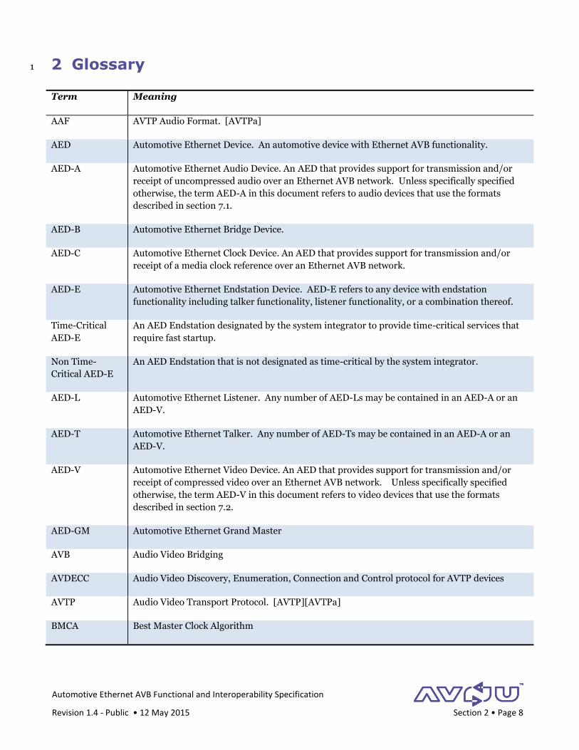
2 Glossary 1
Term Meaning
AAF AVTP Audio Format. [AVTPa]
AED Automotive Ethernet Device. An automotive device with Ethernet AVB functionality.
AED-A Automotive Ethernet Audio Device. An AED that provides support for transmission and/or
receipt of uncompressed audio over an Ethernet AVB network. Unless specifically specified
otherwise, the term AED-A in this document refers to audio devices that use the formats
described in section 7.1.
AED-B Automotive Ethernet Bridge Device.
AED-C Automotive Ethernet Clock Device. An AED that provides support for transmission and/or
receipt of a media clock reference over an Ethernet AVB network.
AED-E Automotive Ethernet Endstation Device. AED-E refers to any device with endstation
functionality including talker functionality, listener functionality, or a combination thereof.
Time-Critical
AED-E
An AED Endstation designated by the system integrator to provide time-critical services that
require fast startup.
Non Time-
Critical AED-E
An AED Endstation that is not designated as time-critical by the system integrator.
AED-L Automotive Ethernet Listener. Any number of AED-Ls may be contained in an AED-A or an
AED-V.
AED-T Automotive Ethernet Talker. Any number of AED-Ts may be contained in an AED-A or an
AED-V.
AED-V Automotive Ethernet Video Device. An AED that provides support for transmission and/or
receipt of compressed video over an Ethernet AVB network. Unless specifically specified
otherwise, the term AED-V in this document refers to video devices that use the formats
described in section 7.2.
AED-GM Automotive Ethernet Grand Master
AVB Audio Video Bridging
AVDECC Audio Video Discovery, Enumeration, Connection and Control protocol for AVTP devices
AVTP Audio Video Transport Protocol. [AVTP][AVTPa]
BMCA Best Master Clock Algorithm
Automotive Ethernet AVB Functional and Interoperability Specification
Revision 1.4 - Public • 12 May 2015 Section 2 • Page 9
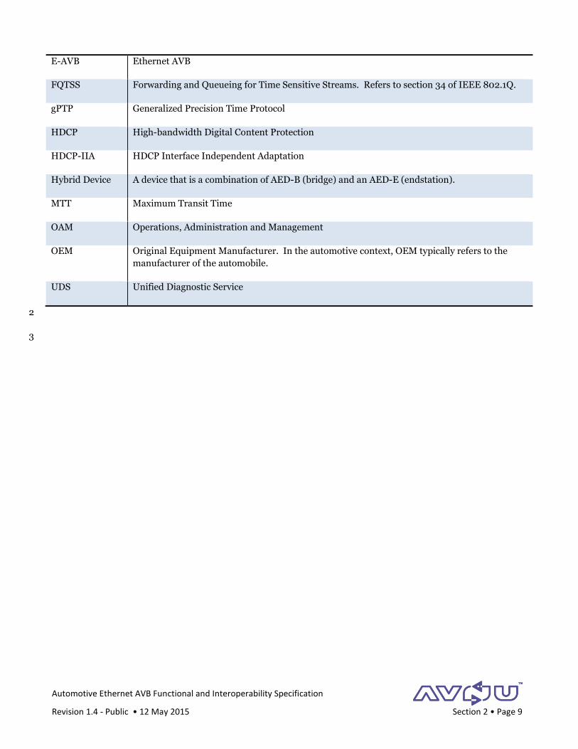
E-AVB Ethernet AVB
FQTSS Forwarding and Queueing for Time Sensitive Streams. Refers to section 34 of IEEE 802.1Q.
gPTP Generalized Precision Time Protocol
HDCP High-bandwidth Digital Content Protection
HDCP-IIA HDCP Interface Independent Adaptation
Hybrid Device A device that is a combination of AED-B (bridge) and an AED-E (endstation).
MTT Maximum Transit Time
OAM Operations, Administration and Management
OEM Original Equipment Manufacturer. In the automotive context, OEM typically refers to the
manufacturer of the automobile.
UDS Unified Diagnostic Service
2
3

Automotive Ethernet AVB Functional and Interoperability Specification
Revision 1.4 - Public • 12 May 2015 Section 3 • Page 10
3 References 1
Name Reference
802.1Q IEEE 802.1Q-2011, “Media Access Control (MAC) Bridges and Virtual Bridge Local Area
Networks,” 31Aug2011.
AltClasses Dave Olsen, Robert Boatright, “AVnu Automotive Alternate SR Classes,” AVnu Technical Note,
Revision 1.3, November 13, 2012.
https://groups.avnu.org/wg/AVnu_Technical/document/download/2222 (Formerly:
http://members.avnu.org/apps/org/workgroup/technical/download.php/3080/Alternate%20Aut
omotive%20SR%20Classes%201.3.pdf)
AVDECC IEEE 1722.1-2013, “IEEE Standard for Device Discovery, Connection Management, and Control
Protocol for IEEE 1722 Based Devices,” 23 August 2013.
AVTP IEEE P1722-2011, “IEEE Standard for Layer 2 Transport Protocol for Time-Sensitive Applications
in Bridged Local Area Networks,” May 2011.
AVTPa IEEE P1722a-D12, “IEEE Standard for Layer 2 Transport Protocol for Time-Sensitive Applications
in Bridged Local Area Networks,” Draft 12, February 9, 2015.
gPTP IEEE Std. 802.1AS-2011 “IEEE Standard for Local and Metropolitan Area Networks – Timing and
Synchronization for Time-Sensitive Applications in Bridged Local Area Networks”
gPTP-Cor IEEE Std. 802.1AS-2011/Cor 1-2013 “IEEE Standard for Local and metropolitan area networks—
Timing and Synchronization for Time-Sensitive Applications in Bridged Local Area Networks—
Corrigendum 1: Technical and Editorial Corrections”
HDCP-IIA High-bandwidth Digital Content Protection System – Interface Independent Adaptation.
http://www.digital-cp.com/files/static_page_files/6FEA6756-1A4B-B294-
D0494084C37A637F/HDCP%20Interface%20Independent%20Adaptation%20Specification%20R
ev2_2_FINAL.pdf
802.1BA IEEE Std 802.1BA‐2011, “Audio Video Bridging (AVB) Systems,” 30 Sept 2011.
2
3
Automotive Ethernet AVB Functional and Interoperability Specification
Revision 1.4 - Public • 12 May 2015 Section 4 • Page 11
4 Scope 1
The scope of this document is to provide a baseline specification of Ethernet AVB functionality on automotive 2
AVB devices as a foundation for an effective certification process. The focus of the document is infotainment 3
systems and basic view cameras. Devices involved with engine control, advanced driver assistance or other 4
functionality are not in the scope of this version of the document. 5
The scope of this specification is at the AVTP service layer [AVTP, AVTPa] and below. This includes the Ethernet 6
PHY, MAC and Bridge, AVB configuration and behavior, and AVTP formats and media clock. Specifically this 7
specification does not cover the behavior of applications built on top of this service layer, or the broader system 8
that contains the AVTP service. 9
Since this specification provides a baseline set of requirements for certification testing it is necessarily limited to 10
key requirements for the targeted use cases. This limitation should not be interpreted as a restriction on the 11
overall functionality of any particular device. Vendors and OEMs can and are encouraged to implement 12
functionality beyond that specified here. 13
This specification defines three device types: endpoint, bridge and hybrid. An endpoint is a device that connects 14
at the edge of the Ethernet network and initiates and/or terminates AVB streams. A bridge is within the Ethernet 15
network and connects endstations and other bridges together to create the network. A hybrid device is a device 16
that contains both an endstation and a bridge within the same “enclosure.” 17
The challenge with the hybrid device is separating the behavior of the endstation from the bridge for the purposes 18
of testing. The Ethernet link between these on a hybrid device is often a PHY-less and connector-less PCB trace 19
that cannot easily be monitored during testing. In such cases, this specification recommends that the hybrid 20
device be tested into 2 different modes, with a different test focus for each mode: 21
1. Endstation Mode: For endstation testing, the vendor designates a single external-facing switch port as the 22
endstation connection. All Ethernet packets to/from the endstation must pass through this port, including 23
test status messages. When testing the device, there will be some observable differences relative to testing a 24
pure endstation, including: 25
Some link-level operation on the connection, such as Auto negotiation (see section 5.1) and gPTP Pdelay 26
(see section 6) will not be directly visible. Instead their effects will at best be indirectly visible in the 27
packets sent by the bridge (e.g. in gPTP Sync packet corrections) 28
External visibility of endstation packets is dependent upon the bridge. If the endstation sends packets 29
before the bridge is ready then they won't be seen. This has a particular impact upon the status messages 30
sent during initialization (see section 5.3). The hybrid device maker should therefore ensure that the 31
bridge is at least "Ethernet Ready" before sending these messages. Internal detection of this state is left to 32
device implementation. 33
The bridge will add some delay to packets sent and received by the endstation. This will be barely 34
perceptible for data packets, but could be visible for certain gPTP protocol packets such as Sync and 35
Signal, which are consumed, processed and then re-originated by the bridge. For instance, if the 36
endstation is the GM then Sync packets coming out will experience a delay according to the bridge's local 37
state machines. Therefore for start-up measurement, the delay for 1 bridge (see Table 6 in section 5.5) 38
Automotive Ethernet AVB Functional and Interoperability Specification
Revision 1.4 - Public • 12 May 2015 Section 4 • Page 12
should be added to the "GM at AVB Sync" timeline in Table-5 for a hybrid device. Generally, this delay 39
should be appropriately accounted for in all event time measurements. 40
If the endstation is the GM, then the Bridge will have already corrected the observed Sync packets. 41
gPTP protocol packets will have the source address of the bridge, not the endstation. 42
2. Bridge Mode: To test the bridge, the vendor shall provide a mechanism for disabling the internal port, and 43
testing shall use only the bridge’s externally facing ports. 44
For the purposes of Exceptions and Diagnostics, it is left to implementation choice whether the Hybrid device 45
reports itself as one or two AED's. However the information content obtainable from the hybrid device shall be the 46
superset of both the endstation and bridge requirements described in this specification. 47
48
Automotive Ethernet AVB Functional and Interoperability Specification
Revision 1.4 - Public • 12 May 2015 Section 5 • Page 13
5 Network and Device Startup 1
5.1 Ethernet Interface Configuration 2
An AED shall provide at least one Ethernet interface. Each Ethernet interface shall operate at either 100 or 1000 3
Mbps. 4
Auto Negotiation on the Ethernet interface shall not be used. The vendor of each device shall either 5
Provide a mechanism for configuring its Ethernet interface(s) into master/slave mode, or 6
Provide documentation on the device’s master/slave mode, if it is preconfigured. 7
5.2 States and Events 8
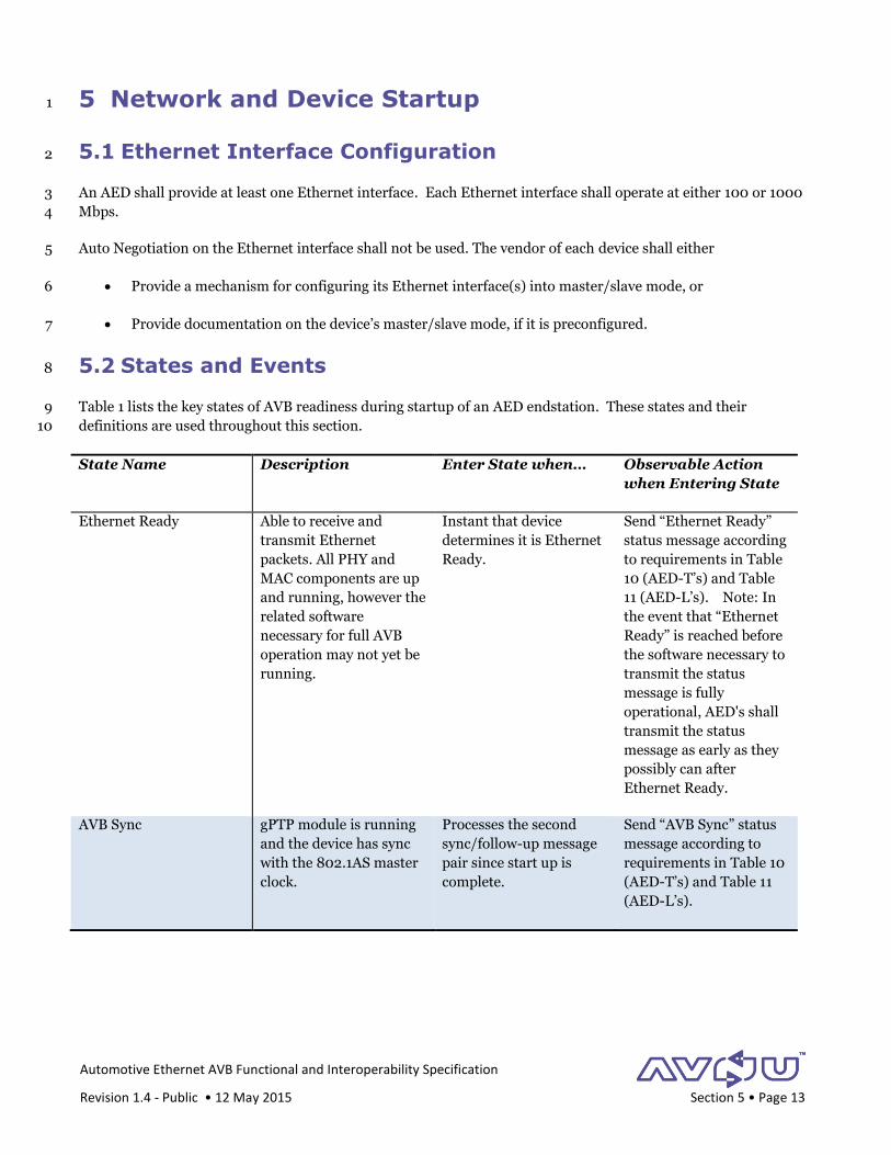
Table 1 lists the key states of AVB readiness during startup of an AED endstation. These states and their 9
definitions are used throughout this section. 10
State Name Description Enter State when… Observable Action
when Entering State
Ethernet Ready Able to receive and
transmit Ethernet
packets. All PHY and
MAC components are up
and running, however the
related software
necessary for full AVB
operation may not yet be
running.
Instant that device
determines it is Ethernet
Ready.
Send “Ethernet Ready”
status message according
to requirements in Table
10 (AED-T’s) and Table
11 (AED-L’s). Note: In
the event that “Ethernet
Ready” is reached before
the software necessary to
transmit the status
message is fully
operational, AED's shall
transmit the status
message as early as they
possibly can after
Ethernet Ready.
AVB Sync gPTP module is running
and the device has sync
with the 802.1AS master
clock.
Processes the second
sync/follow-up message
pair since start up is
complete.
Send “AVB Sync” status
message according to
requirements in Table 10
(AED-T’s) and Table 11
(AED-L’s).
Automotive Ethernet AVB Functional and Interoperability Specification
Revision 1.4 - Public • 12 May 2015 Section 5 • Page 14
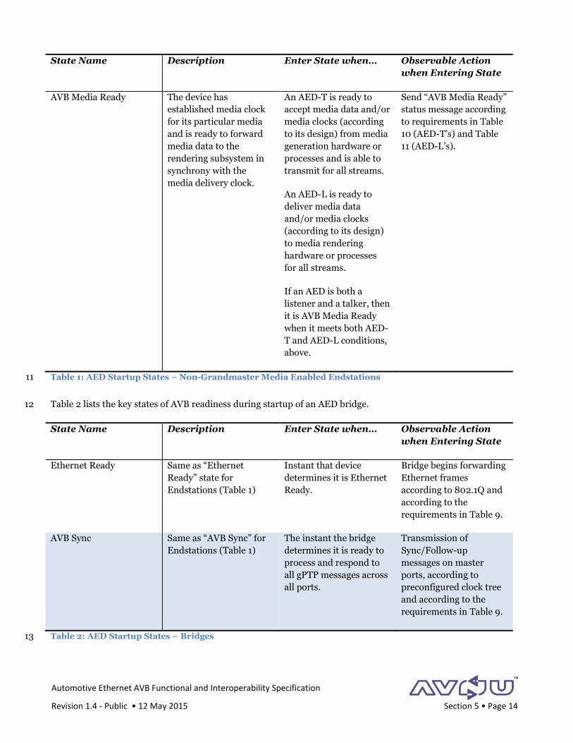
State Name Description Enter State when… Observable Action
when Entering State
AVB Media Ready The device has
established media clock
for its particular media
and is ready to forward
media data to the
rendering subsystem in
synchrony with the
media delivery clock.
An AED-T is ready to
accept media data and/or
media clocks (according
to its design) from media
generation hardware or
processes and is able to
transmit for all streams.
An AED-L is ready to
deliver media data
and/or media clocks
(according to its design)
to media rendering
hardware or processes
for all streams.
If an AED is both a
listener and a talker, then
it is AVB Media Ready
when it meets both AED-
T and AED-L conditions,
above.
Send “AVB Media Ready”
status message according
to requirements in Table
10 (AED-T’s) and Table
11 (AED-L’s).
Table 1: AED Startup States – Non-Grandmaster Media Enabled Endstations 11
Table 2 lists the key states of AVB readiness during startup of an AED bridge. 12
State Name Description Enter State when… Observable Action
when Entering State
Ethernet Ready Same as “Ethernet
Ready” state for
Endstations (Table 1)
Instant that device
determines it is Ethernet
Ready.
Bridge begins forwarding
Ethernet frames
according to 802.1Q and
according to the
requirements in Table 9.
AVB Sync Same as “AVB Sync” for
Endstations (Table 1)
The instant the bridge
determines it is ready to
process and respond to
all gPTP messages across
all ports.
Transmission of
Sync/Follow-up
messages on master
ports, according to
preconfigured clock tree
and according to the
requirements in Table 9.
Table 2: AED Startup States – Bridges 13
Automotive Ethernet AVB Functional and Interoperability Specification
Revision 1.4 - Public • 12 May 2015 Section 5 • Page 15
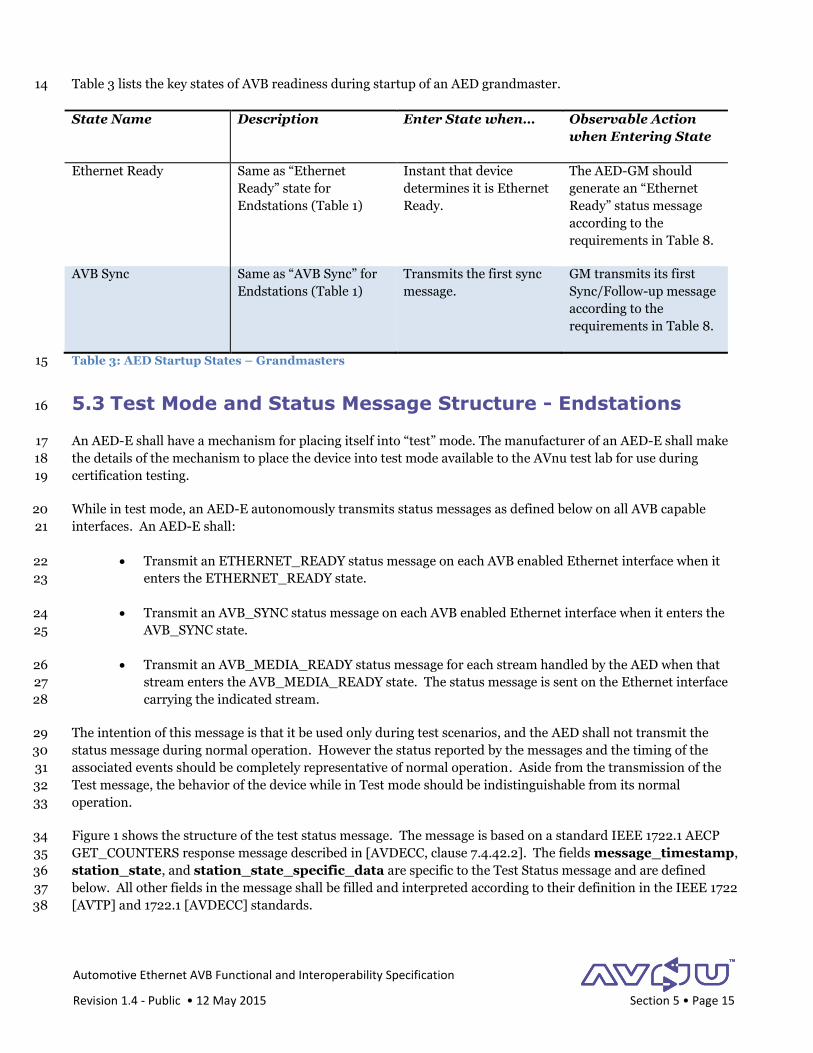
Table 3 lists the key states of AVB readiness during startup of an AED grandmaster. 14
State Name Description Enter State when… Observable Action
when Entering State
Ethernet Ready Same as “Ethernet
Ready” state for
Endstations (Table 1)
Instant that device
determines it is Ethernet
Ready.
The AED-GM should
generate an “Ethernet
Ready” status message
according to the
requirements in Table 8.
AVB Sync Same as “AVB Sync” for
Endstations (Table 1)
Transmits the first sync
message.
GM transmits its first
Sync/Follow-up message
according to the
requirements in Table 8.
Table 3: AED Startup States – Grandmasters 15
5.3 Test Mode and Status Message Structure - Endstations 16
An AED-E shall have a mechanism for placing itself into “test” mode. The manufacturer of an AED-E shall make 17
the details of the mechanism to place the device into test mode available to the AVnu test lab for use during 18
certification testing. 19
While in test mode, an AED-E autonomously transmits status messages as defined below on all AVB capable 20
interfaces. An AED-E shall: 21
Transmit an ETHERNET_READY status message on each AVB enabled Ethernet interface when it 22
enters the ETHERNET_READY state. 23
Transmit an AVB_SYNC status message on each AVB enabled Ethernet interface when it enters the 24
AVB_SYNC state. 25
Transmit an AVB_MEDIA_READY status message for each stream handled by the AED when that 26
stream enters the AVB_MEDIA_READY state. The status message is sent on the Ethernet interface 27
carrying the indicated stream. 28
The intention of this message is that it be used only during test scenarios, and the AED shall not transmit the 29
status message during normal operation. However the status reported by the messages and the timing of the 30
associated events should be completely representative of normal operation. Aside from the transmission of the 31
Test message, the behavior of the device while in Test mode should be indistinguishable from its normal 32
operation. 33
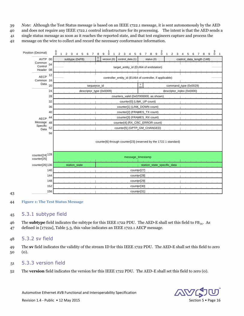
Figure 1 shows the structure of the test status message. The message is based on a standard IEEE 1722.1 AECP 34
GET_COUNTERS response message described in [AVDECC, clause 7.4.42.2]. The fields message_timestamp, 35
station_state, and station_state_specific_data are specific to the Test Status message and are defined 36
below. All other fields in the message shall be filled and interpreted according to their definition in the IEEE 1722 37
[AVTP] and 1722.1 [AVDECC] standards. 38
Automotive Ethernet AVB Functional and Interoperability Specification
Revision 1.4 - Public • 12 May 2015 Section 5 • Page 16
Note: Although the Test Status message is based on an IEEE 1722.1 message, it is sent autonomously by the AED 39
and does not require any IEEE 1722.1 control infrastructure for its processing. The intent is that the AED sends a 40
single status message as soon as it reaches the reported state, and that test engineers capture and process the 41
message on the wire to collect and record the necessary conformance information. 42
43
Figure 1: The Test Status Message 44
5.3.1 subtype field 45
The subtype field indicates the subtype for this IEEE 1722 PDU. The AED-E shall set this field to FB16. As 46
defined in [1722a], Table 5.3, this value indicates an IEEE 1722.1 AECP message. 47
5.3.2 sv field 48
The sv field indicates the validity of the stream ID for this IEEE 1722 PDU. The AED-E shall set this field to zero 49
(0). 50
5.3.3 version field 51
The version field indicates the version for this IEEE 1722 PDU. The AED-E shall set this field to zero (0). 52
counter[6] through counter[23] (reserved by the 1722.1 standard)
0 1 2 3 4 5 6 7 8 9 0 1 2 3 4 5 6 7 8 9 0 1 2 3 4 5 6 7 8 9 0 10 1 2 3
subtype (0xFB)sv
(0)version (0) control_data (1)
target_entity_id (EUI64 of endstation)
00
04
08
12
16
20
control_data_length (148)AVTP
Common
Control
Header
Position (Decimal)
status (0)
controller_entity_id (EUI64 of controller, if applicable)
sequence_id command_type (0x0029)
descriptor_type (0x0009) descriptor_index (0x0000)
u
(1)
counters_valid (0x07000000, as shown)
AECP
Common
Data
AECP
Message
Specific
Data
24
28
32 counter[0] (LINK_UP count)
counter[1] (LINK_DOWN count)
counter[2] (FRAMES_TX count)
counter[3] (FRAMES_RX count)
counter[4] (RX_CRC_ERROR count)
counter[5] (GPTP_GM_CHANGED)
message_timestamp
counter[28]
counter[29]
counter[30]
counter[31]
counter[27]
counter[26] station_state
counter[24]
counter[25]
station_state_specific_data
36
40
44
48
52
56
128
136
140
144
148
152
156
Automotive Ethernet AVB Functional and Interoperability Specification
Revision 1.4 - Public • 12 May 2015 Section 5 • Page 17
5.3.4 control_data field 53
IEEE 1722.1 uses the control_data field to indicate the message type of an AECP message. [AVDECC, clause 54
9.2.1.1.5] The AED-E shall set this field to 116, indicating that this is an AVDECC entity model response message. 55
5.3.5 status field 56
IEEE 1722.1 uses the status field to indicate the success/failure of the command/response AECP message pair. 57
[AVDECC, clause 9.2.1.1.6] The AED-E shall set this field to zero (0), indicating that this is a successful response 58
message. 59
5.3.6 control_data_length field 60
The control_data_length field indicates the number of octets in this message following the target_entity_id 61
field. Since the status message has a fixed length, the AED-E shall set this field to 148 (9416). 62
5.3.7 target_entity_id field 63
IEEE 1722.1 renames the stream_id field from the IEEE 1722 stream header to target_entity_id and uses it to 64
indicate the 64-bit IEEE extended unique identifier (EUI-64) for the AED-E transmitting the status message. The 65
AED-E shall set the target_entity_id field to its EUI-64. 66
The AED-E shall set its EUI-64 target_entity_id using the derivation from its EUI-48 MAC address, according 67
to the EUI-48 tutorial document5. Use of this derivation maintains a one-to-one relationship between the device’s 68
MAC address and the EUI-64 used in the status message. 69
5.3.8 controller_entity_id field 70
IEEE 1722.1 uses the controller_entity_id field to indicate the EUI-64 of the destination AVDECC controller 71
for this response message. However, the status message has no corresponding controller since it will be 72
intercepted by test equipment. Therefore the AED-E shall set the controller_entity_id field to zero(0). 73
5.3.9 sequence_id field 74
The sequence_id field is incremented on each command sent . The AED-E shall increment the sequence_id 75
on each status message it sends. The AED-E may initialize the field to any value on startup. 76
5.3.10 u field 77
The u field indicates whether or not the message is a solicited or unsolicited response. A value of one (1) indicates 78
that it is unsolicited. [AVDECC, clause 7.4.39.1] The AED-E shall set the u field to one (1). 79
5.3.11 command_type field 80
The AED-E shall set the command_type field to value 002916. As specified in [AVDECC], clause 9.2.1.2 and 81
table 7.125, this value indicates that this is a GET_COUNTERS command. 82
5 https://standards.ieee.org/develop/regauth/tut/eui48.pdf
Automotive Ethernet AVB Functional and Interoperability Specification
Revision 1.4 - Public • 12 May 2015 Section 5 • Page 18
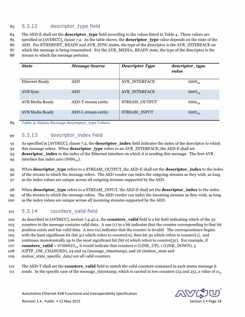
5.3.12 descriptor_type field 83
The AED-E shall set the descriptor_type field according to the values listed in Table 4. These values are 84
specified in [AVDECC], clause 7.2. As the table shows, the descriptor_type value depends on the state of the 85
AED. For ETHERNET_READY and AVB_SYNC states, the type of the descriptor is the AVB_INTERFACE on 86
which the message is being transmitted. For the AVB_MEDIA_READY state, the type of the descriptor is the 87
stream to which the message pertains. 88
State Message Source Descriptor Type descriptor_type
value
Ethernet Ready AED AVB_INTERFACE 000916
AVB Sync AED AVB_INTERFACE 000916
AVB Media Ready AED-T stream entity STREAM_OUTPUT 000616
AVB Media Ready AED-L stream entity STREAM_INPUT 000516
Table 4: Status Message descriptor_type Values 89
5.3.13 descriptor_index field 90
As specified in [AVDECC], clause 7.2, the descriptor_index field indicates the index of the descriptor to which 91
this message refers. When descriptor_type refers to an AVB_INTERFACE, the AED-E shall set 92
descriptor_index to the index of the Ethernet interface on which it is sending this message. The first AVB 93
interface has index zero (000016). 94
When descriptor_type refers to a STREAM_OUTPUT, the AED-E shall set the descriptor_index to the index 95
of the stream to which the message refers. The AED vendor can index the outgoing streams as they wish, as long 96
as the index values are unique across all outgoing streams supported by the AED. 97
When descriptor_type refers to a STREAM_INPUT, the AED-E shall set the descriptor_index to the index 98
of the stream to which the message refers. The AED vendor can index the incoming streams as they wish, as long 99
as the index values are unique across all incoming streams supported by the AED. 100
5.3.14 counters_valid field 101
As described in [AVDECC], section 7.4.42.2, the counters_valid field is a bit field indicating which of the 32 102
counters in the message contains valid data. A one (1) in a bit indicates that the counter corresponding to that bit 103
position exists and has valid data. A zero (0) indicates that the counter is invalid. The correspondence begins 104
with the least significant bit (bit 31) which refers to counter[0], then bit 30 which refers to counter[1], and 105
continues monotonically up to the most significant bit (bit 0) which refers to counter[31]. For example, if 106
counters_valid = 0700002316 it would indicate that counters 0 (LINK_UP), 1 (LINK_DOWN), 5 107
(GPTP_GM_CHANGED), 24 and 25 (message_timestamp), and 26 (station_state and 108
station_state_specific_data) are all valid counters. 109
The AED-T shall set the counters_valid field to match the valid counters contained in each status message it 110
sends. In the specific case of the message_timestamp, which is carried in two counters (24 and 25), a value of 112 111

Automotive Ethernet AVB Functional and Interoperability Specification
Revision 1.4 - Public • 12 May 2015 Section 5 • Page 19
indicates that the message_timestamp field is valid. Any other value for these two bits (002, 012, or 102) indicate 112
that the message_timestamp field is not valid. 113
5.3.15 counter[0] field (Link_Up count) 114
The counter[0] field indicates the count of link-up events since the AED-E’s startup. It is defined in [AVDECC], 115
section 7.4.42.2.2, Table 7.135. It is recommended but not mandatory that an AED-E supports this field. If the 116
AED-E does support this counter, it shall set it to the link-up count at the time it creates the status message. If an 117
AED-E does not support this counter, it shall set the counter to zero (0000000016). 118
5.3.16 counter[1] field (Link_Down count) 119
The counter[1] field indicates the count of link-down events since the AED-E’s startup. It is defined in 120
[AVDECC], section 7.4.42.2.2, Table 7.135. It is recommended but not mandatory that an AED-E supports this 121
field. If the AED-E does support this counter, it shall set it to the link-down count at the time it creates the status 122
message. If the AED-E does not support this counter, it shall set the counter to zero (0000000016). 123
5.3.17 counter[2] field (Frames_Tx count) 124
The counter[2] field indicates the count of transmitted Ethernet frames since the AED-E’s startup. It is defined 125
in [AVDECC], section 7.4.42.2.2, Table 7.135. It is recommended but not mandatory that an AED-E supports this 126
field. If the AED-E does support this counter, it shall set it to the transmitted frame count at the time it creates 127
the status message. If the AED-E does not support this counter, it shall set the counter to zero (0000000016). 128
5.3.18 counter[3] field (Frames_Rx count) 129
The counter[3] field indicates the count of received Ethernet frames since the AED-E’s startup. It is defined in 130
[AVDECC], section 7.4.42.2.2, Table 7.135. It is recommended but not mandatory that an AED-E supports this 131
field. If the AED-E does support this counter, it shall set it to the received frame count at the time it creates the 132
status message. If the AED-E does not support this counter, it shall set the counter to zero (0000000016). 133
5.3.19 counter[4] field (Rx_CRC_Error count) 134
The counter[4] field indicates the count of received Ethernet frames having a CRC error since the AED-E’s 135
startup. It is defined in [AVDECC], section 7.4.42.2.2, Table 7.135. It is recommended but not mandatory that an 136
AED-E supports this field. If the AED-E does support this counter, it shall set it to the received errored-frame 137
count at the time it creates the status message. If the AED-E does not support this counter, it shall set the counter 138
to zero (0000000016). 139
5.3.20 counter[5] field (GPTP_GM_Changed count) 140
The counter[5] field indicates the count gPTP grandmaster changes since the AED-E’s startup. It is defined in 141
[AVDECC], section 7.4.42.2.2, Table 7.135. It is recommended but not mandatory that an AED-E supports this 142
field. If the AED-E does support this counter, it shall set it to gPTP grandmaster change count at the time it 143
creates the status message. If the AED-E does not support this counter, it shall set the counter to zero 144
(0000000016). 145
Note: Since the Best Master Clock Algorithm (BMCA) is not running in AED’s conforming to this version of the 146
AVnu automotive specification, it is expected that the GPTP_GM_Changed field will always by zero 147
Automotive Ethernet AVB Functional and Interoperability Specification
Revision 1.4 - Public • 12 May 2015 Section 5 • Page 20
(0000000016). However, the specification retains the 1722.1 definition of this field since future versions of this 148
specification may allow operation of BMCA. 149
5.3.21 counter[6] through counter[23] fields 150
The fields counter[6] through counter[23] are reserved by the 1722.1 standard [AVDECC]. The AED-E shall 151
set these counters to zero (0000000016). 152
5.3.22 counter[24] and counter[25] fields (message_timestamp) 153
The message_timestamp field occupies counters 24 and 25 of the base AECP message. The 154
message_timestamp field indicates the gPTP time at which the device entered the indicated state. The 155
message_timestamp field is in nanoseconds and is constructed from both the gPTP seconds and nanoseconds 156
by the following formula: 157
timestamp = (𝐴𝑆𝑠𝑒𝑐 × 109 + AS𝑛𝑠) mod 264 158
where 𝐴𝑆𝑠𝑒𝑐 is the gPTP seconds field, and 𝐴𝑆𝑛𝑠 is the gPTP nanoseconds field. This value rolls over approximately 159
every 585 years (264
365 × 24 × 60 × 60 × 109 = 584.9), giving plenty of room for measuring AED startup time. 160
If the AED-E is transmitting this message to signal its entry into the “Ethernet Ready” state (as given in the 161
definition for counter[26], octet 0), it does not yet have a valid gPTP clock. In this case, the AED-E shall set the 162
message_timestamp field to zero (000000000000000016). 163
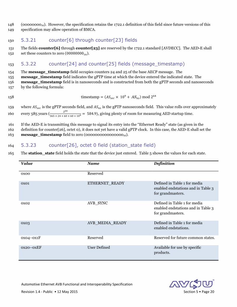
5.3.23 counter[26], octet 0 field (station_state field) 164
The station_state field holds the state that the device just entered. Table 5 shows the values for each state. 165
Value Name Definition
0x00 Reserved
0x01 ETHERNET_READY Defined in Table 1 for media
enabled endstations and in Table 3
for grandmasters.
0x02 AVB_SYNC Defined in Table 1 for media
enabled endstations and in Table 3
for grandmasters.
0x03 AVB_MEDIA_READY Defined in Table 1 for media
enabled endstations.
0x04–0x1F Reserved Reserved for future common states.
0x20–0xEF User Defined Available for use by specific
products.
Automotive Ethernet AVB Functional and Interoperability Specification
Revision 1.4 - Public • 12 May 2015 Section 5 • Page 21
Value Name Definition
0xF0–0xFF Experimental Experimental states. Not for
production.
Table 5: Station State Values 166
5.3.24 counter[26], octet 1-3 field (station_state_specific_data) 167
The station_state_specific_data field holds data that is specific to each state. If not specifically defined by a 168
state, the talker shall set station_state_specific_data to zero (0) and the receiver shall ignore it. 169
5.3.25 counter[27] through counter[31] 170
The fields counter[27] through counter[31] are not used in the status message. The AED-E shall set these 171
fields to zero (0). 172
5.4 Addressing 173
The AED-E shall use the standard structure for an AVTPDU as defined in IEEE 1722. [1722] For Ethernet 174
addressing, it shall always use the multicast address 01-1B-C5-0A-C0-00 as the destination address when 175
transmitting the test status message. This address has been assigned from AVnu’s block of 4096 OUIs. AVnu’s 176
base identifier is an OUI–36, with the value 00–1B–C5–0A–C. 177
5.5 Startup Timing 178
An individual AED’s startup timing must operate within the context of the overall startup process for a vehicle 179
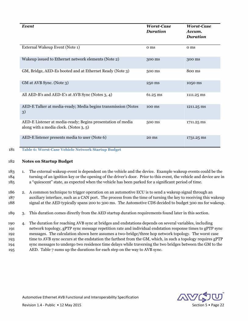
network. Table 6 shows the worst-case startup budget for a vehicle’s Ethernet network. 180
Automotive Ethernet AVB Functional and Interoperability Specification
Revision 1.4 - Public • 12 May 2015 Section 5 • Page 22
Event Worst-Case
Duration
Worst-Case
Accum.
Duration
External Wakeup Event (Note 1) 0 ms 0 ms
Wakeup issued to Ethernet network elements (Note 2) 300 ms 300 ms
GM, Bridge, AED-Es booted and at Ethernet Ready (Note 3) 500 ms 800 ms
GM at AVB Sync. (Note 3) 250 ms 1050 ms
All AED-B’s and AED-E’s at AVB Sync (Notes 3, 4) 61.25 ms 1111.25 ms
AED-E Talker at media-ready; Media begins transmission (Notes
3)
100 ms 1211.25 ms
AED-E Listener at media-ready; Begins presentation of media
along with a media clock. (Notes 3, 5)
500 ms 1711.25 ms
AED-E listener presents media to user (Note 6) 20 ms 1731.25 ms
Table 6: Worst-Case Vehicle Network Startup Budget 181
Notes on Startup Budget 182
1. The external wakeup event is dependent on the vehicle and the device. Example wakeup events could be the 183
turning of an ignition key or the opening of the driver’s door. Prior to this event, the vehicle and device are in 184
a “quiescent” state, as expected when the vehicle has been parked for a significant period of time. 185
2. A common technique to trigger operation on an automotive ECU is to send a wakeup signal through an 186
auxiliary interface, such as a CAN port. The process from the time of turning the key to receiving this wakeup 187
signal at the AED typically spans 200 to 300 ms. The Automotive CDS decided to budget 300 ms for wakeup. 188
3. This duration comes directly from the AED startup duration requirements found later in this section. 189
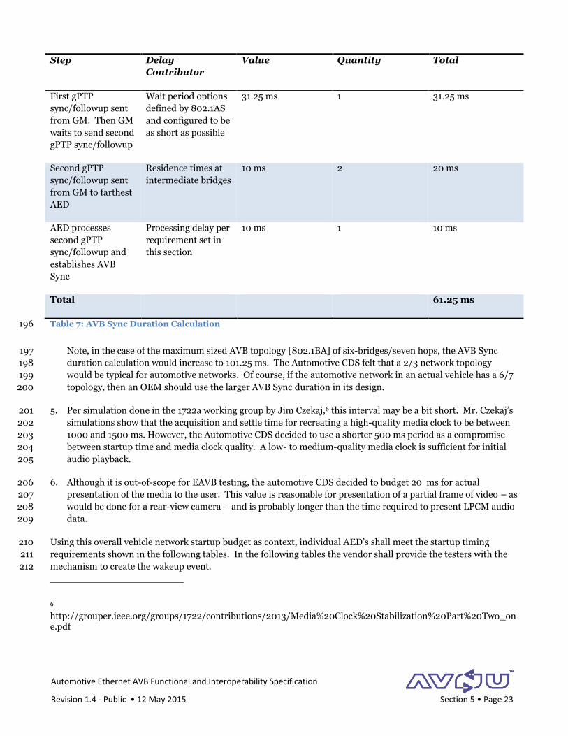
4. The duration for reaching AVB sync at bridges and endstations depends on several variables, including 190
network topology, gPTP sync message repetition rate and individual endstation response times to gPTP sync 191
messages. The calculation shown here assumes a two-bridge/three hop network topology. The worst case 192
time to AVB sync occurs at the endstation the farthest from the GM, which, in such a topology requires gPTP 193
sync messages to undergo two residence time delays while traversing the two bridges between the GM to the 194
AED. Table 7 sums up the durations for each step on the way to AVB sync. 195
Automotive Ethernet AVB Functional and Interoperability Specification
Revision 1.4 - Public • 12 May 2015 Section 5 • Page 23
Step Delay
Contributor
Value Quantity Total
First gPTP
sync/followup sent
from GM. Then GM
waits to send second
gPTP sync/followup
Wait period options
defined by 802.1AS
and configured to be
as short as possible
31.25 ms 1 31.25 ms
Second gPTP
sync/followup sent
from GM to farthest
AED
Residence times at
intermediate bridges
10 ms 2 20 ms
AED processes
second gPTP
sync/followup and
establishes AVB
Sync
Processing delay per
requirement set in
this section
10 ms 1 10 ms
Total 61.25 ms
Table 7: AVB Sync Duration Calculation 196
Note, in the case of the maximum sized AVB topology [802.1BA] of six-bridges/seven hops, the AVB Sync 197
duration calculation would increase to 101.25 ms. The Automotive CDS felt that a 2/3 network topology 198
would be typical for automotive networks. Of course, if the automotive network in an actual vehicle has a 6/7 199
topology, then an OEM should use the larger AVB Sync duration in its design. 200
5. Per simulation done in the 1722a working group by Jim Czekaj,6 this interval may be a bit short. Mr. Czekaj’s 201
simulations show that the acquisition and settle time for recreating a high-quality media clock to be between 202
1000 and 1500 ms. However, the Automotive CDS decided to use a shorter 500 ms period as a compromise 203
between startup time and media clock quality. A low- to medium-quality media clock is sufficient for initial 204
audio playback. 205
6. Although it is out-of-scope for EAVB testing, the automotive CDS decided to budget 20 ms for actual 206
presentation of the media to the user. This value is reasonable for presentation of a partial frame of video – as 207
would be done for a rear-view camera – and is probably longer than the time required to present LPCM audio 208
data. 209
Using this overall vehicle network startup budget as context, individual AED’s shall meet the startup timing 210
requirements shown in the following tables. In the following tables the vendor shall provide the testers with the 211
mechanism to create the wakeup event. 212
6 http://grouper.ieee.org/groups/1722/contributions/2013/Media%20Clock%20Stabilization%20Part%20Two_one.pdf
Automotive Ethernet AVB Functional and Interoperability Specification
Revision 1.4 - Public • 12 May 2015 Section 5 • Page 24
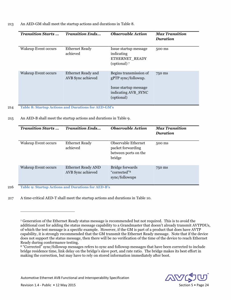
An AED-GM shall meet the startup actions and durations in Table 8. 213
Transition Starts … Transition Ends… Observable Action Max Transition
Duration
Wakeup Event occurs Ethernet Ready
achieved
Issue startup message
indicating
ETHERNET_READY
(optional) 7
500 ms
Wakeup Event occurs Ethernet Ready and
AVB Sync achieved
Begins transmission of
gPTP sync/followup.
Issue startup message
indicating AVB_SYNC
(optional)
750 ms
Table 8: Startup Actions and Durations for AED-GM’s 214
An AED-B shall meet the startup actions and durations in Table 9. 215
Transition Starts … Transition Ends… Observable Action Max Transition
Duration
Wakeup Event occurs Ethernet Ready
achieved
Observable Ethernet
packet forwarding
between ports on the
bridge
500 ms
Wakeup Event occurs Ethernet Ready AND
AVB Sync achieved
Bridge forwards
“corrected”8
sync/followups
750 ms
Table 9: Startup Actions and Durations for AED-B’s 216
A time-critical AED-T shall meet the startup actions and durations in Table 10. 217
7 Generation of the Ethernet Ready status message is recommended but not required. This is to avoid the additional cost for adding the status message capability to a Grandmaster that doesn’t already transmit AVTPDUs, of which the test message is a specific example. However, if the GM is part of a product that does have AVTP capability, it is strongly recommended that the GM transmit the Ethernet Ready message. Note that if the device does not support the status message, then there will be no verification of the time of the device to reach Ethernet Ready during conformance testing. 8 “Corrected” sync/followup messages refers to sync and followup messages that have been corrected to include bridge residence time, link delay on the bridge’s slave port, and rate ratio. The bridge makes its best effort in making the correction, but may have to rely on stored information immediately after boot.
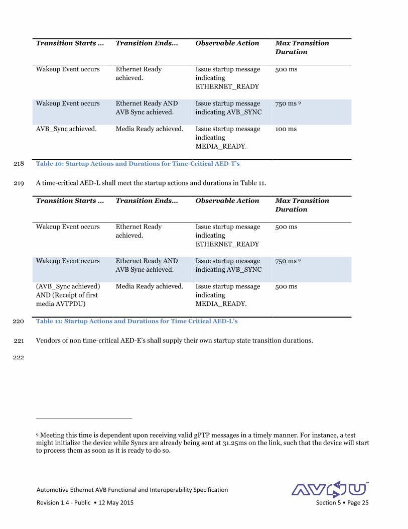
Automotive Ethernet AVB Functional and Interoperability Specification
Revision 1.4 - Public • 12 May 2015 Section 5 • Page 25
Transition Starts … Transition Ends… Observable Action Max Transition
Duration
Wakeup Event occurs Ethernet Ready
achieved.
Issue startup message
indicating
ETHERNET_READY
500 ms
Wakeup Event occurs Ethernet Ready AND
AVB Sync achieved.
Issue startup message
indicating AVB_SYNC
750 ms 9
AVB_Sync achieved. Media Ready achieved. Issue startup message
indicating
MEDIA_READY.
100 ms
Table 10: Startup Actions and Durations for Time-Critical AED-T’s 218
A time-critical AED-L shall meet the startup actions and durations in Table 11. 219
Transition Starts … Transition Ends… Observable Action Max Transition
Duration
Wakeup Event occurs Ethernet Ready
achieved.
Issue startup message
indicating
ETHERNET_READY
500 ms
Wakeup Event occurs Ethernet Ready AND
AVB Sync achieved.
Issue startup message
indicating AVB_SYNC
750 ms 9
(AVB_Sync achieved)
AND (Receipt of first
media AVTPDU)
Media Ready achieved. Issue startup message
indicating
MEDIA_READY.
500 ms
Table 11: Startup Actions and Durations for Time Critical AED-L’s 220
Vendors of non time-critical AED-E’s shall supply their own startup state transition durations. 221
222
9 Meeting this time is dependent upon receiving valid gPTP messages in a timely manner. For instance, a test might initialize the device while Syncs are already being sent at 31.25ms on the link, such that the device will start to process them as soon as it is ready to do so.
Automotive Ethernet AVB Functional and Interoperability Specification
Revision 1.4 - Public • 12 May 2015 Section 6 • Page 26
6 Generalized Precision Time Protocol (gPTP) 1
The Generalized Precision Time Protocol (gPTP) provides an accurate time base to all elements in an Ethernet 2
network. In the automotive environment this time base can be used in both Audio/Video applications and Control 3
applications to provide synchronization between events. The use for gPTP in an automotive audio/video system is 4
to provide a timing reference for recovery of media clocks in listener devices and providing synchronous media 5
delivery across multiple listener devices. 6
The automotive environment is unique in that it is a closed system. Every network device is known prior to 7
startup and devices do not enter or leave the network, except in the case of failures. Because of the closed nature 8
of the automotive network, it is possible to simplify and improve gPTP startup performance. Specifically, 9
functions like election of a grand master and calculations of wire delays are tasks that can be optimized for a 10
closed system. 11
6.1 Scope 12
This section covers only the differences between the plug-and-play10 implementation and the implementation for 13
a closed automotive environment of the gPTP standard. In both implementations, the gPTP standard provides the 14
functional basis, and an AED shall implement all requirements of gPTP that are not discussed in this section in 15
accordance with the relevant standards. [gPTP][gPTP-Cor] 16
This section proposes concepts that may require changes to the plug-and-play implementation of the gPTP state 17
machines and other operations. Details of these changes are not specified here and left to the implementer. 18
All references of the form [gPTP x.x.x.x] refer to the specified clause in IEEE Std. 802.1AS-2011. [gPTP][gPTP-19
Cor] 20
6.2 gPTP Configuration 21
Due to the closed and static architecture of an automotive network, an OEM can optimize the startup time of the 22
timing system by preconfiguring certain gPTP values and making some gPTP values persistent through a power 23
cycle. 24
The requirements in this document are based on the assumption that there is a single AED-GM (GrandMaster) 25
assigned within a vehicle network. 26
For the purposes of AVnu certification testing, the AED vendor shall provide a mechanism for configuring the 27
values described in this section at the time they submit a device for certification testing. Certification test 28
personnel will use this mechanism to properly configure the device for testing. 29
10 “Plug-and-Play” refers to those implementations designed to work “out-of-the-box” with other AVB products and not require any engineering on the part of the user or network provider. The IEEE 802.1BA-2011 describes the overall scenario for the “plug-and-play” scenario.
Automotive Ethernet AVB Functional and Interoperability Specification
Revision 1.4 - Public • 12 May 2015 Section 6 • Page 27
6.2.1 Static gPTP Values 30
Static gPTP values are configured prior to system startup, stored in non-volatile storage, and are not expected to 31
change during system operation. 32
6.2.1.1 Grandmaster Information and Topology 33
It is expected in an automotive environment to have a fixed gPTP GrandMaster (AED-GM). An OEM will often 34
configure the automotive network to have a single, fixed AED-GM and with all other AED’s operating as slaves to 35
that grandmaster. This means that: 36
The gPTP port role of all time-aware ports. The port of a standalone AED-GM shall be in master role. For 37
all non-GM end-stations, the port should be in the slave role. For a device that contains bridge 38
functionality (AED-B), ports will be in either the master or slave role, depending on whether or not the 39
port points towards the AED-GM. 40
AEDs do not support BMCA and the GrandMaster needs to be identified. A new variable isGM should be 41
defined for each AED. isGM is set TRUE for the AED-GM and FALSE for all other AEDs. 42
6.2.1.2 asCapable [gPTP 10.2.4.1] 43
All AEDs that have time-aware ports on which they will receive or transmit gPTP timing information shall set the 44
value of asCapable to TRUE for these ports when the link is up. This allows time aware ports to begin receiving or 45
sending timing information with as little delay after startup as possible. The state returned for asCapable for these 46
ports when link is down is an implementation choice. 47
6.2.1.3 initialLogPdelayReqInterval [gPTP 11.5.2.2] 48
The AED shall have a mechanism to preconfigure initialLogPdelayReqInterval on all time-aware ports to a value 49
that corresponds with the desired initial Pdelay request interval for the port. See 6.2.3.2. 50
In the case of ports in the Master port role, the OEM or system integrator can, if they desire, set the 51
initialLogPdelayInterval to 127 [gPTP 11.5.2.2] to disable the sending of Pdelay Requests. Note that the AED with 52
a slave port must still adhere to [gPTP] and always respond to any Pdelay Requests it receives on that slave port. 53
6.2.1.4 initialLogSyncInterval [gPTP 10.2.4.4] 54
The AED shall have a mechanism to preconfigure initialLogSyncInterval on all time-aware ports to a value that 55
corresponds with the desired initial Sync interval for the port. See 6.2.3.1. 56
6.2.1.5 operLogPdelayReqInterval 57
operLogPdelayReqInterval is the operational Pdelay request interval. A device moves to this value on all slave 58
ports once the measured values have stabilized. The AED shall have a mechanism to preconfigure 59
operLogPdelayReqInterval on all time-aware ports to a value that corresponds with the desired Pdelay request 60
interval for the port. See 6.2.3.2. 61
Automotive Ethernet AVB Functional and Interoperability Specification
Revision 1.4 - Public • 12 May 2015 Section 6 • Page 28
6.2.1.6 operLogSyncInterval 62
operLogSyncInterval is the Sync interval that a device moves to and signals on a slave port once it has achieved 63
synchronization. The AED shall have a mechanism to preconfigure operLogSyncInterval on all time-aware ports 64
to a value that corresponds with the desired Sync interval for the port. See 6.2.3.1. 65
6.2.2 Persistent gPTP Values 66
Persistent values are values that an AED stores in non-volatile storage upon update and restores to the stored 67
value on startup. Saving these values allows an AED to decrease its startup time and improve initial timing 68
accuracy. 69
6.2.2.1 neighborPropDelay [gPTP 10.2.4.7] 70
A Pdelay calculation determines the propagation delay between nodes and stores this value in neighborPropDelay. 71
The neighborPropDelay is used in calculating the current time. In a closed automotive network with fixed wire 72
lengths the calculated neighborPropDelay should change little over time. An AED shall store neighborPropDelay 73
in non-volatile memory and use the stored value during its next startup. The stored neighborPropDelay value for 74
a port should be set in production or service and otherwise does not change. This allows the device to calculate 75
accurate time prior running the Pdelay algorithm. As soon as possible after startup, the AED shall return to 76
standard Pdelay message processing and begin calculation of neighborPropDelay according to standard 77
techniques. 78
The gPTP GrandMaster does not use its neighborPropDelay in calculating time since it is the source of time. 79
Therefore the AED-GM is not required to calculate or save neighborPropDelay. 80
It is possible that the neighborPropDelay may change due to cabling changes while an AED is in the power off 81
state. For instance, this may occur in situations where the car has undergone repair or replacement of parts. In 82
such a case, there may be timing inaccuracies on system startup. These inaccuracies will resolve after standard 83
Pdelay calculations resume. 84
If the stored neighborPropDelay value is zero (0) then the value has never been initialized and shall be updated 85
with the actual value once neighborPropDelay has stabilized. In normal operation -- except in the case of a wiring 86
change -- this value should not change. If the actual value of neighborPropDelay differs from the stored value by 87
more than 100ns then the AED shall update the stored value to the actual value. 88
NOTE: Raw Pdelay values tend to jitter due to clock resolutions and need to be filtered in order to obtain an 89
accurate and stable Pdelay. The details of this filtering are left to the implementation. When this document 90
discusses Pdelay and neighborPropDelay it is referring to the filtered/stabilized values and not raw values. 91
6.2.2.2 rateRatio [gPTP 10.2.2.1.7] 92
The rateRatio is equal to the ratio of the frequency of the grandmaster to the frequency of the LocalClock. The 93
rateRatio is used in calculating the current time. An AED may save this value prior to power down and restore it 94
on power up. Use of a stored rateRatio may allow the device to compute accurate time more quickly on startup 95
than using the default initial rateRatio of unity. However as this ratio does vary with time and temperature, the 96
additional accuracy may not be significant. 97
Automotive Ethernet AVB Functional and Interoperability Specification
Revision 1.4 - Public • 12 May 2015 Section 6 • Page 29
6.2.2.3 neighborRateRatio [gPTP 10.2.4.6] 98
The neighborRateRatio is an estimate of the ratio of the frequency of the LocalClock entity of the time-aware 99
system at the other end of the link attached to this port, to the frequency of the LocalClock entity of this time-100
aware system. The neighborRateRatio is used in calculating the current time. An AED may save this value prior 101
to power down and restore it on power up. Use of a stored neighbor RateRatio may allow the device to compute 102
accurate time more quickly on startup than using the default initial neighborRateRatio of unity. However as this 103
ratio does vary with time and temperature, the additional accuracy may not be significant. 104
6.2.3 Management Updated Values 105
Management updated values are values that an AED stores in volatile storage, but have default configurations 106
available in non-volatile memory. A management program in response to specific events occurring or states being 107
entered can update these values. 108
6.2.3.1 SyncInterval [gPTP, clause 10.2.4.5] 109
The SyncInterval defines the mean time-synchronization event message generation interval for the port. The 110
default value defined in [gPTP] is 125 milliseconds. The SyncInterval has a direct impact on system 111
synchronization time at startup as an AED must receive a minimum of two (2) Sync messages to obtain basic 112
synchronization. However after initial synchronization is achieved, synchronization can be maintained with a 113
much larger SyncInterval, with the corresponding benefits of reduced CPU load and network overhead. 114
To take advantage of reduced CPU load and network overhead, a gPTP slave port on an AED may request that the 115
SyncInterval be increased through use of the gPTP Signaling message with the message interval request TLV. The 116
initial sync interval is set with the variable initialLogSyncInterval, and the operational sync interval is set with the 117
variable operLogSyncInterval. A master port on an AED shall process and correctly act upon a received gPTP 118
Signaling message within the larger of the following intervals after receiving the message: 119
Two (2) of the current sync message intervals, 120
250ms. 121
See 6.2.6 for required values for initialLogSyncInterval and operLogSyncInterval. 122
AED-E devices that support the gPTP signaling message and whose value of operLogSyncInterval differs from the 123
value of initialLogSyncInterval, shall send the gPTP Signaling message to reduce the logSyncInterval no longer 124
than sixty (60) seconds after achieving gPTP synchronization. 125
An AED-B may use the gPTP signaling technique to alter the SyncInterval on its Slave Port based upon the sync 126
intervals on its master ports. In such a case the AED-B’s Slave port’s SyncInterval should track a value equal to the 127
shortest SyncInterval across all the active AS master role ports on the bridge. If the the AED-B does reduce the 128
SyncInterval on its slave port, it shall do it within 4 seconds of the event that causes the update. 129
If an AED port experiences a link down/up event then, on link up, the Sync Interval state machine shall revert to 130
its initialization state. Specifically: 131
On an AED-E slave port, the device shall clear any state associated with prior signaling, and the device shall 132
await time synchronization before signaling a slower rate to the master. 133
Automotive Ethernet AVB Functional and Interoperability Specification
Revision 1.4 - Public • 12 May 2015 Section 6 • Page 30
On an AED-B master port, the device shall revert SyncInterval to initialLogSyncInterval. The AED-B shall 134
signal for an updated interval on its slave port as required. 135
On an AED-B slave port, the AED-B shall expect the link partner port to revert to it's initialLogSyncInterval, 136
and then signal the required rate on the port according to the current rate on each of its slave master ports. 137
On an AED-GM master port, the device shall revert SyncInterval to initialLogSyncInterval and the device 138
should await further signals. 139
6.2.3.2 pdelayReqInterval 140
The pdelayReqInterval defines the mean Pdelay_Req message generation interval for the port. Pdelay_Req 141
messages are sent to determine the neighborPropDelay. In a fixed topology network this value should not change 142
over time making it desirable to run the calculation very infrequently. The variable initialLogPdelayReqInterval 143
controls the startup rate of pdelayReqInterval. 144
Once the neighborPropDelay has stabilized, the value of LogPdelayReqInterval should be set to a value that 145
reduces network overhead and CPU load associated with computing neighborPropDelay. AED-E devices whose 146
value of operLogPdelayInterval differs from the value of initialLogPdelayInterval, shall set their 147
logPdelayReqInterval to operLogPdelayInterval no longer than sixty (60) seconds after achieving gPTP 148
synchronization. 149
See 6.2.6 for required values for initialLogPdelayReqInterval and operLogPdelayReqInterval. 150
6.2.4 gPTP Signaling Message [gPTP 10.5.4] 151
The gPTP Signaling Message with Message interval request TLV [gPTP, clause 10.5.4.2.2] is designed to allow a 152
port to adjust the rate of reception of messages from its link partner port. This TLV can be used in gPTP to request 153
a change in timeSyncInterval, linkDelayInterval and announceInterval on the partner port. In the automotive 154
profile, this message is used only to request modification of the timeSyncInterval on the partner port. AEDs with a 155
slave role port should support transmission of this TLV. AEDs with a master role port shall support processing of 156
this TLV on each master role port. An AED shall ignore any gPTP Signaling Messages received on a slave role port. 157
If an AED supports transmission of the gPTP Signaling Message on a slave role port, then, when doing so, it shall 158
set the timeSyncInterval to the desired value (see section 6.2.3.1). The values for linkDelayInterval and 159
announceInterval shall be set to 127, indicating that such messages should not be sent. 160
When processing a received gPTP Signaling Message on a master role port, an AED shall update the syncInterval 161
for the receiving port accordingly and shall ignore values for linkDelayInterval and announceInterval. 162
6.2.5 FollowUp TLV’s 163
AED’s shall include the FollowUp information TLV on all FollowUp messages [gPTP, clause 11.4.4.3]. 164
6.2.6 Required Values for gPTP 165
All ports shall support the full range of possible values of gPTP variables for time critical and non-time critical 166
ports as listed in Table 12 and Table 13. 167

Automotive Ethernet AVB Functional and Interoperability Specification
Revision 1.4 - Public • 12 May 2015 Section 6 • Page 31
Time critical Port Min Max
initialLogPDelayReqInterval 1s 1s
operLogPdelayReqInterval 1s 8s
initialLogSyncInterval 31.25ms 125ms
operLogSyncInterval 125ms 1s
Table 12 - gPTP values for time critical systems 168
Non-time critical Port Min Max
initialLogPDelayReqInterval 1s 1s
operLogPdelayReqInterval 1s 8s
initialLogSyncInterval 125ms 125ms
operLogSyncInterval 125ms 1s
Table 13 - gPTP values for non-time critical systems 169
170
6.3 gPTP Operation 171
In the automotive environment, AED’s execute gPTP operations somewhat differently than in a standard 172
implementation. These differences are: 173
BMCA shall not execute. Conceptually, each device should be preconfigured with the result that BMCA 174
would have arrived at if it had been previously running and had reached a quiescent operating state. 175
Announce messages are neither required nor expected in an automotive network since BMCA is not being 176
executed. With no BMCA there will always be exactly one device in the network that is configured as GM 177
and no other device will ever become the GM. 178
No verification of sourcePortIdentity. Because there are no Announce messages in the automotive 179
network, it is not possible for an AED slave to know the sourcePortIdentity of its link partner until the 180
first Sync message is received. Therefore an AED Slave port shall not perform verification of the 181
sourcePortIdentity field of Sync and Followup messages. 182
The AED-GM should begin sending Sync and FollowUp messages as soon as possible after startup. (See 183
Clause 5 Network and Device Startup.) 184
syncReceiptTimeout [gPTP 10.6.3.1] behavior for non GM AED-B devices is modified as follows: 185
Automotive Ethernet AVB Functional and Interoperability Specification
Revision 1.4 - Public • 12 May 2015 Section 6 • Page 32
o AED-B Sync processing during loss of Sync: During normal operation, the AED-B will receive 186
and process Sync messages on its Slave port. If the AED-B detects a termination of these Sync 187
messages on its Slave port, the AED-B shall continue sending Sync messages out of its Master 188
Ports using the most recent valid record received on the slave port as its basis. The AED-B shall 189
use the preciseOriginTimestamp from the most recent valid record received from the GM in all 190
FollowUp messages it sends, and it shall advance the correctionField in all Sync and FollowUp 191
messages it sends, to reflect the time that has passed since receipt of the most recent valid record. 192
The AED-B shall use its local timebase and any known cumulativeScaledRateOffset to make the 193
calculations for these messages. 194
o AED-B Sync recovery: If the AED-B receives a valid Sync message on its Slave port then it shall 195
update that record and resume normal Sync operation. The Bridge is not required to avoid, 196
mitigate or report a phase jump in this circumstance. 197
o AED-B Sync Absence: On startup if an AED-B does not receive a Sync message on a Slave port 198
within a configurable time, then it shall use a default time record and begin sending Sync 199
messages with constant preciseOriginTimestamp and advancing correction on its Master role 200
ports. The time to wait for an initial Sync message is user configurable, but shall never be greater 201
than 20 seconds. 202
o AED-B Fixed GM Information: Regardless of the status of Sync message reception, the AED-B 203
shall not modify gmTimeBaseIndicator, lastGMPhaseChange or scaledLastGMFreqChange fields 204
in any Sync or FollowUp messages that it sends. 205
o AED-E Time Jumps: An AED-E Slave may see jumps in the time it receives in Sync messages due 206
to the switches in Sync message generation between the AED-GM and the AED-B. Time jumps 207
may also occur due to daylight savings time or other clock adjustments. The AED-E shall handle 208
the discontinuity in time according to the exception handling procedure described in section 209
9.3.2. 210
o AED-E Holdover: An AED-E Slave that is not currently receiving Sync messages will continue to 211
advance its gPTP wall clock based on its local timebase and any known 212
cumulativeScaledRateOffset. 213
o AED-E Sync recovery: If the AED-E receives a valid Sync message on its Slave port then it shall 214
update its time record and resume normal Sync operation. The AED-E shall handle the 215
discontinuity in time according to the exception handling procedure described in section 9.3.2. 216
Since there is a fixed clock-spanning tree, AED-B implementations may choose to only perform delay 217
measurement in one direction. An AED-B is not required to initiate peer delay requests on its time-aware 218
ports that are in the Master role. 219
In the case where an AED-B is the gPTP Grandmaster, if the GM operation ceases then the AED-B shall 220
stop sending Syncs on master ports. Connected AED-E devices should go into holdover, while a connected 221
AED-B should implement the syncReceiptTimeout behavior described above. 222
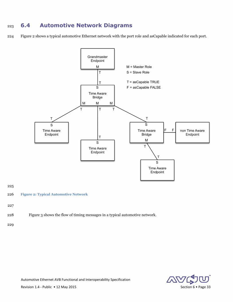
Automotive Ethernet AVB Functional and Interoperability Specification
Revision 1.4 - Public • 12 May 2015 Section 6 • Page 33
6.4 Automotive Network Diagrams 223
Figure 2 shows a typical automotive Ethernet network with the port role and asCapable indicated for each port. 224
225
Figure 2: Typical Automotive Network 226
227
Figure 3 shows the flow of timing messages in a typical automotive network. 228
229

Automotive Ethernet AVB Functional and Interoperability Specification
Revision 1.4 - Public • 12 May 2015 Section 6 • Page 34
230
Figure 3: Flow of Timing Messages 231
232
PSg
P
SgP
Time AwareEndpoint
Time AwareEndpoint
Time AwareBridge
Time AwareBridge
GrandmasterEndpoint
Time AwareEndpoint
non Time AwareEndpoint
S = SyncP= Pdelay_ReqSg = Signaling
Follow_Up, Pdelay_Resp and Pdelay_Resp_Follow_Up are not shown and expected to be sent as defined.
S
S
S
S
S
Sg P
Sg P
Sg
Automotive Ethernet AVB Functional and Interoperability Specification
Revision 1.4 - Public • 12 May 2015 Section 7 • Page 35
7 Media Formats 1
Automotive infotainment use cases require the Ethernet-AVB network to carry a variety of media formats. They 2
include uncompressed audio, compressed video, container formats that carry a variety of compressed media, and 3
clock distribution formats. 4
Note: The AVnu Automotive Working Group will define additional media transport formats in future revisions of 5
this document. As these formats are added, vendors of AEDs that support the added formats will need to seek 6
certification for them. 7
7.1 AVTP Audio Format (AAF) 8
If an AED-A supports the AAF format, then it shall support the AVTP Audio Format (AAF) as defined in IEEE-9
1722a. [AVTPa, clause 8] AED-A's that support other audio formats, such as the 61883-6 format, will not have 10
their audio format certified under the AVnu Automotive profile. 11
An AED-A shall support the sixteen (16) bit integer sample format as defined in IEEE-1722a. [AVTPa, clause 12
8.2.1] 13
An AED-A shall support at least one of 48kHz and 44.1kHz audio sample rates, as defined in IEEE-1722a. [AVTPa, 14
clause 8.2.2] 15
An AED-A talker shall support at least one of either “full” or sparse timestamp mode as defined in IEEE-1722a. 16
[AVTPa, Clause 8.2] The vendor of the AED-A needs to communicate which timestamp mode their device 17
supports in its application for certification testing. 18
An AED-A listener shall support both full and sparse timestamp modes as defined in IEEE-1722a. [AVTPa, Clause 19
8.2.5] 20
Dynamic changes in audio layout can occur during normal operation of a vehicle audio system. For instance the 21
user may switch from a 5.1 surround song to a stereo song. In this case, the number of actual audio channels 22
being transmitted to the amplifier doesn’t change, but the layout for using those channels does change. To 23
accommodate this, the event field in the AAF header [AVTPa, Clause 8.2.6] is defined in Table 14 to signal a 24
dynamic change in audio channel layout. An AED-A shall support at least one of the dynamic layouts 0, 1, 2, 3 or 25
4 as defined in Table 14. If an AED-A supports the static layout (layout 0), then the vendor needs to communicate 26
which static mode audio layouts the device supports in the application for certification testing. 27
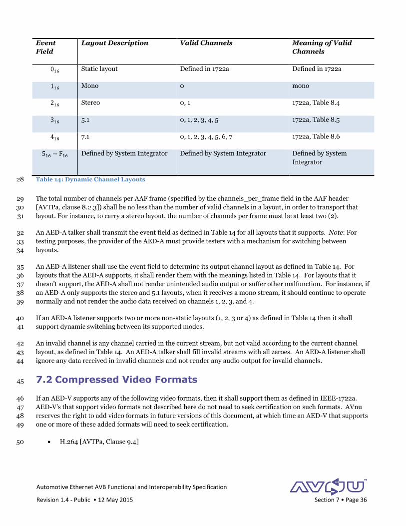
Automotive Ethernet AVB Functional and Interoperability Specification
Revision 1.4 - Public • 12 May 2015 Section 7 • Page 36
Event
Field
Layout Description Valid Channels Meaning of Valid
Channels
016 Static layout Defined in 1722a Defined in 1722a
116 Mono 0 mono
216 Stereo 0, 1 1722a, Table 8.4
316 5.1 0, 1, 2, 3, 4, 5 1722a, Table 8.5
416 7.1 0, 1, 2, 3, 4, 5, 6, 7 1722a, Table 8.6
516 − F16 Defined by System Integrator Defined by System Integrator Defined by System
Integrator
Table 14: Dynamic Channel Layouts 28
The total number of channels per AAF frame (specified by the channels_per_frame field in the AAF header 29
[AVTPa, clause 8.2.3]) shall be no less than the number of valid channels in a layout, in order to transport that 30
layout. For instance, to carry a stereo layout, the number of channels per frame must be at least two (2). 31
An AED-A talker shall transmit the event field as defined in Table 14 for all layouts that it supports. Note: For 32
testing purposes, the provider of the AED-A must provide testers with a mechanism for switching between 33
layouts. 34
An AED-A listener shall use the event field to determine its output channel layout as defined in Table 14. For 35
layouts that the AED-A supports, it shall render them with the meanings listed in Table 14. For layouts that it 36
doesn’t support, the AED-A shall not render unintended audio output or suffer other malfunction. For instance, if 37
an AED-A only supports the stereo and 5.1 layouts, when it receives a mono stream, it should continue to operate 38
normally and not render the audio data received on channels 1, 2, 3, and 4. 39
If an AED-A listener supports two or more non-static layouts (1, 2, 3 or 4) as defined in Table 14 then it shall 40
support dynamic switching between its supported modes. 41
An invalid channel is any channel carried in the current stream, but not valid according to the current channel 42
layout, as defined in Table 14. An AED-A talker shall fill invalid streams with all zeroes. An AED-A listener shall 43
ignore any data received in invalid channels and not render any audio output for invalid channels. 44
7.2 Compressed Video Formats 45
If an AED-V supports any of the following video formats, then it shall support them as defined in IEEE-1722a. 46
AED-V's that support video formats not described here do not need to seek certification on such formats. AVnu 47
reserves the right to add video formats in future versions of this document, at which time an AED-V that supports 48
one or more of these added formats will need to seek certification. 49
H.264 [AVTPa, Clause 9.4] 50

Automotive Ethernet AVB Functional and Interoperability Specification
Revision 1.4 - Public • 12 May 2015 Section 7 • Page 37
Motion JPEG (MJPEG) [AVTPa, Clause 9.3] 51
7.2.1 H.264 52
An AED-V talker that supports H.264 shall produce an AVTP packet stream that is compliant with the H.264 53
AVTP mapping. [AVTPa, Clause 9.4] 54
An AED-V listener that supports H.264 shall render video with no user observable glitches or artifacts when 55
receiving an AVTP stream compliant with the H.264 mapping. [AVTPa, Clause 9.4] Note: Full testing of the video 56
decoder is beyond the scope of AVnu testing. However, an AED-V listener should be able demonstrate video 57
decode and rendering capabilities sufficient to satisfy visual inspection by a human tester. 58
7.2.2 Motion JPEG (MJPEG) 59
An AED-V talker that supports MJPEG shall produce an AVTP packet stream that is compliant with the MJPEG 60
AVTP mapping. [AVTPa, Clause 9.3] 61
An AED-V listener that supports MJPEG shall render video with no user observable glitches or artifacts when 62
receiving an AVTP stream compliant with the MJPEG mapping. [AVTPa, Clause 9.3] Note: Full testing of the 63
video decoder is beyond the scope of AVnu testing. However, an AED-V listener should be able demonstrate video 64
decode and rendering capabilities sufficient to satisfy visual inspection by a human tester. 65
7.3 MPEG2-TS Container Format 66
An AED talker that supports MPEG2 transport stream container format shall produce an AVTP packet stream that 67
is compliant with the 61883-4 AVTP mapping. [AVTP, Clause 6] 68
7.4 Clock Reference Format (CRF) 69
An AED-C audio talker shall support an audio sample CRF (CRF_AUDIO_SAMPLE) as defined in IEEE-1722a. 70
[AVTPa, Clause 11] In addition to verifying compliance with the standard, testing will record frequency and jitter 71
of the timestamps in the transmitted CRF stream. The AED-C audio CRF talker shall produce a clock reference 72
stream whose observed frequency value as measured from CRF timestamps varies from nominal by no more than 73
+/-100PPM. 74
If an AED-C is both a CRF listener and a talker generating a stream (of any format) that is synchronized to the 75
received CRF stream, then the presentation timestamps of the generated stream shall be within 5% of the 76
associated timestamp positions in the original CRF stream. 77
Note: Because access to the recovered media clock cannot be guaranteed in the test lab, CRF requirements on 78
listeners are not currently part of this specification. 79
80
Automotive Ethernet AVB Functional and Interoperability Specification
Revision 1.4 - Public • 12 May 2015 Section 8 • Page 38
8 Stream Reservation (SR) Classes 1
The automotive Ethernet-AVB network has several constraints that a typical Ethernet network does not. In 2
particular, automotive networks are often limited to a 100Mbps data rate. This is due to the need to choose a 3
physical layer that operates on a single pair and without shielding to reduce wiring harness cost and weight. This 4
tight limit to 100Mbps strongly encourages bandwidth efficient engineering. 5
Simultaneously, engineers of Ethernet AVB networks face the age-old requirement of designing cost effective 6
solutions. Implementations of the two existing AVB SR classes (class A and class B) require AVTPDUs to be 7
transmitted in 125μs and 250μs intervals, respectively. These intervals place another constraint – especially for 8
uncompressed audio streams – that result in media data blocks that are unnatural for today’s DSP and DMA 9
engines that typically operate on data blocks of 32 or 64 audio samples. 10
These two issues – network bandwidth efficiency and natural data sizing – have driven some creative thinking 11
regarding SR classes. AVnu’s automotive working group has taken advantage of the self-contained nature of the 12
automotive network to define SR classes that are specific to the automotive use case and that help to solve 13
bandwidth efficiency and data sizing issues. Note that even though the automotive working group has defined 14
more than two SR classes, this specification does not require any device to simultaneously support more than 2 SR 15
classes. 16
8.1 Stream Reservation Class Requirements 17
An AED shall support at least one of the SR classes from Table 15. Design of these SR classes is described in 18
[AltClasses] and pays careful attention to overall latency. 19
Note that most of the current AVB network implementations are limited to a maximum of two SR classes, since 20
they were designed to support only classes A and B from [802.1BA]. This specification purposely does not impose 21
this limitation, in order to allow future implementations that may need more than two traffic classes. 22
Class A B 64 Sample,
48kHz
64 sample,
44.1kHz
Measurement
Interval
125μs 250μs 1333μs 1451μs
Table 15: SR Class Measurement Intervals for Automotive Networks 23
For each SR class that it supports, an AED shall support a measurement interval as described in Table 15. 24
An AED shall use class IDs 5 and 6 to identify the SR classes associated with each stream. An OEM will typically 25
configure the vehicle network to use no more than two SR classes and so that streams with higher priority use 26
class ID 6, and streams with lower priority use class ID 5. Table 16 gives an example of SR class ID use for the 27
classes defined in this specification. Note that even when the vehicle’s network uses SR classes not defined in this 28
specification, the network devices still use class IDs 5 and 6. 29
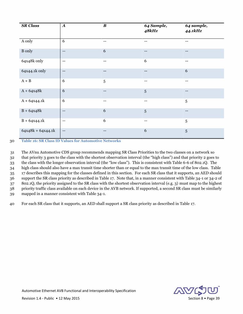
Automotive Ethernet AVB Functional and Interoperability Specification
Revision 1.4 - Public • 12 May 2015 Section 8 • Page 39
SR Class A B 64 Sample,
48kHz
64 sample,
44.1kHz
A only 6 -- -- --
B only -- 6 -- --
64x48k only -- -- 6 --
64x44.1k only -- -- -- 6
A + B 6 5 -- --
A + 64x48k 6 -- 5 --
A + 64x44.1k 6 -- -- 5
B + 64x48k -- 6 5 --
B + 64x44.1k -- 6 -- 5
64x48k + 64x44.1k -- -- 6 5
Table 16: SR Class ID Values for Automotive Networks 30
The AVnu Automotive CDS group recommends mapping SR Class Priorities to the two classes on a network so 31
that priority 3 goes to the class with the shortest observation interval (the “high class”) and that priority 2 goes to 32
the class with the longer observation interval (the “low class”). This is consistent with Table 6-6 of 802.1Q. The 33
high class should also have a max transit time shorter than or equal to the max transit time of the low class. Table 34
17 describes this mapping for the classes defined in this section. For each SR class that it supports, an AED should 35
support the SR class priority as described in Table 17. Note that, in a manner consistent with Table 34-1 or 34-2 of 36
802.1Q, the priority assigned to the SR class with the shortest observation interval (e.g. 3) must map to the highest 37
priority traffic class available on each device in the AVB network. If supported, a second SR class must be similarly 38
mapped in a manner consistent with Table 34-1. 39
For each SR class that it supports, an AED shall support a SR class priority as described in Table 17. 40

Automotive Ethernet AVB Functional and Interoperability Specification
Revision 1.4 - Public • 12 May 2015 Section 8 • Page 40
SR Classes on
Vehicle Network
A B 64 Sample,
48kHz
64 sample,
44.1kHz
A only 3 -- -- --
B only -- 3 -- --
64x48k only -- -- 3 --
64x44.1k only -- -- -- 3
A + B 3 2 -- --
A + 64x48k 3 -- 2 --
A + 64x44.1k 3 -- -- 2
B + 64x48k -- 3 2 --
B + 64x44.1k -- 3 -- 2
64x48k + 64x44.1k -- -- 3 2
Table 17: SR Class Priority Values for Automotive Networks 41
An AED shall set regeneration override values according to 802.1Q-2011, clause 6.9.4. 42
Note: AVnu compliance testing will test all SR classes supported by the AED. Testing will be a standard FQTSS 43
test, including class performance and packet jitter measurements. The vendor of the AED must either 44
Disclose the procedure for configuring the streams on their product, including SR class ID, SR class 45
priority, and measurement interval, or 46
Communicate the static settings for the streams, if they are preconfigured into the device. 47
48
8.2 Presentation Time Parameters 49
8.2.1 Maximum Transit Time 50
The Maximum Transit Time (also known as Presentation Time Offset) is the time offset added at the talker to the 51
gPTP observation time to create the presentation time of the packet at the listener. Table 18 specifies the 52
maximum transit times for each SR class. For each class it supports, the AED shall support the maximum transit 53
time specified in Table 18. 54

Automotive Ethernet AVB Functional and Interoperability Specification
Revision 1.4 - Public • 12 May 2015 Section 8 • Page 41
Class Maximum Transit Time
A 2 ms
B 10 ms (Note 1)
64x48k 15 ms
64x44.1k 15 ms
Table 18: SR Class Maximum Transit Times 55
Notes on Table 18: 56
1. The standard maximum transit time for class B streams [802.1BA] assumes two wireless segments in its 57
calculations. This does not apply to automotive applications. Therefore this specification appropriately 58
reduces MTT for class B. 59
The Maximum Transit Times shown in Table 18 are defaults. OEMs may specify alternative values for their 60
applications. 61
The MTT values for classes A and B come from IEEE 1722. The MTT values for the 64 sample classes are based on 62
the example data shown in Table 19, originally from [AltClasses]. These calculations use the formula defined in 63
IEEE 802.1BA, section 6.5 and assumes 8 mono channels of audio in 16-bit AAF format. A 15ms MTT provides 64
sufficient headroom so that the MTT is sufficient to cover worst-case network topologies and stream bandwidths. 65
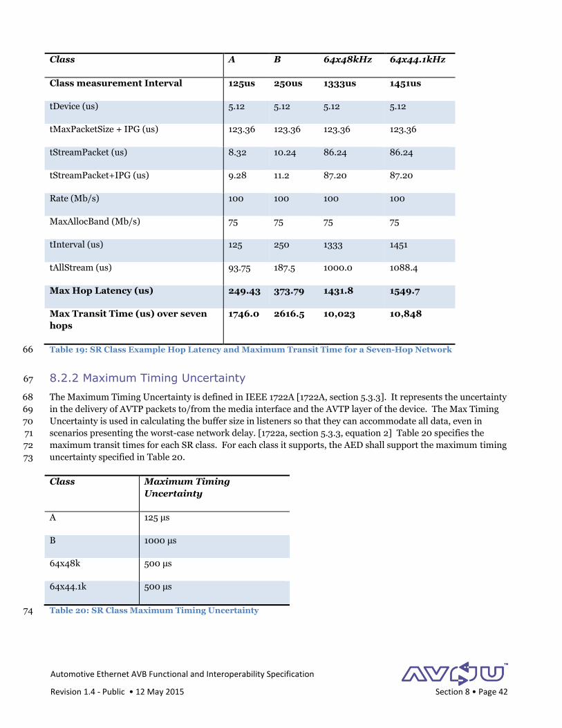
Automotive Ethernet AVB Functional and Interoperability Specification
Revision 1.4 - Public • 12 May 2015 Section 8 • Page 42
Class A B 64x48kHz 64x44.1kHz
Class measurement Interval 125us 250us 1333us 1451us
tDevice (us) 5.12 5.12 5.12 5.12
tMaxPacketSize + IPG (us) 123.36 123.36 123.36 123.36
tStreamPacket (us) 8.32 10.24 86.24 86.24
tStreamPacket+IPG (us) 9.28 11.2 87.20 87.20
Rate (Mb/s) 100 100 100 100
MaxAllocBand (Mb/s) 75 75 75 75
tInterval (us) 125 250 1333 1451
tAllStream (us) 93.75 187.5 1000.0 1088.4
Max Hop Latency (us) 249.43 373.79 1431.8 1549.7
Max Transit Time (us) over seven
hops
1746.0 2616.5 10,023 10,848
Table 19: SR Class Example Hop Latency and Maximum Transit Time for a Seven-Hop Network 66
8.2.2 Maximum Timing Uncertainty 67
The Maximum Timing Uncertainty is defined in IEEE 1722A [1722A, section 5.3.3]. It represents the uncertainty 68
in the delivery of AVTP packets to/from the media interface and the AVTP layer of the device. The Max Timing 69
Uncertainty is used in calculating the buffer size in listeners so that they can accommodate all data, even in 70
scenarios presenting the worst-case network delay. [1722a, section 5.3.3, equation 2] Table 20 specifies the 71
maximum transit times for each SR class. For each class it supports, the AED shall support the maximum timing 72
uncertainty specified in Table 20. 73
Class Maximum Timing
Uncertainty
A 125 μs
B 1000 μs
64x48k 500 μs
64x44.1k 500 μs
Table 20: SR Class Maximum Timing Uncertainty 74
Automotive Ethernet AVB Functional and Interoperability Specification
Revision 1.4 - Public • 12 May 2015 Section 8 • Page 43
8.3 Stream Reservation Requirements 75
An AED shall support statically configured reservations for all AVB streams. 76
Note: AVnu compliance testing will test all streams supported by the AED. Testing will be a standard FQTSS 77
test, including class performance and packet jitter measurements. The vendor of the AED shall either 78
Disclose the procedure for configuring the streams on their product, including SR class ID, SR class 79
priority, and measurement interval, or 80
Communicate the static settings for the streams, if they are “hardwired” into the device. 81
82

Automotive Ethernet AVB Functional and Interoperability Specification
Revision 1.4 - Public • 12 May 2015 Section 9 • Page 44
9 Exception Handling 1
All implementations of Automotive Ethernet networks will likely need to comply with the OEM or System 2
Integrator requirements for error and exception handling. These will differ, and so the specifics are beyond the 3
scope of this document. However this section does identify a subset of exceptions associated with the AVB and 4
Ethernet service layers, and provides guidance on how these should be handled. 5
These exception types are discussed in the following sections: 6
AVB Device Failure 7
Ethernet link state events and data loss 8
802.1AS exceptions 9
IEEE 1722 Media Stream exceptions 10
This document assumes that all devices operating in a vehicular environment shall be developed to be highly 11
robust and resilient to exception conditions during startup, shutdown and normal operation. Generally speaking, 12
devices should employ techniques that allow exception conditions to be reported and, where possible, 13
automatically corrected without driver or service intervention, and without significant functional degradation in 14
the vehicle. 15
The AVB device shall retain error logs or diagnostic codes for subsequent service retrieval and analysis via a 16
mechanism defined by the System Integrator, such as a UDS based method. For the purposes of AVnu 17
certification testing, the AED vendor shall provide a mechanism for retrieving logged data at the time they submit 18
a device for certification testing. Certification test personnel will use this mechanism to verify all logged data. 19
9.1 AVB Device Failure 20
While not required by this specification, it is generally expected that each device attached to the AVB network will 21
have the following exception handling properties: 22
Recover and continue operation when encountering recoverable exceptions 23
Restart in the case of fatal errors 24
Watchdog timer support to self-restart in the case of a software hang 25
Log exceptions and provide a mechanism for their retrieval 26
Operate with the in-car OAM and network management sub-system 27
While the AVB protocols can conceivably be used to perform certain OAM functions (e.g. partner health check), it 28
is not their primary purpose and, unless otherwise stated, they should not be relied upon for this purpose. 29

Automotive Ethernet AVB Functional and Interoperability Specification
Revision 1.4 - Public • 12 May 2015 Section 9 • Page 45
9.2 Ethernet Exceptions 30
9.2.1 Link State Events 31
9.2.1.1 Link-Down 32
A link-down event on a port indicates the loss of Ethernet connectivity to the link partner on that port. All traffic, 33
including media and AVB protocol traffic, will stop. In a traditional, non-automotive network, link-down will 34
typically occur due to a failure or restart of the link partner device, a cable fault, a cable unplug event or the link 35
partner device being administratively disabled. Since an automotive network is typically static and unmanaged, 36
this event is most likely due to either a link partner failure/restart or a cable fault. Note that a link down event 37
during a system shut down is not considered to be an exception. The System Integrator will often define additional 38
system behavior in the case of a link-down event, but at a minimum the AED shall always timestamp and log any 39
link-down event for later retrieval. 40
9.2.1.2 Link-Up 41
When link-up follows a link-down event on a port, this indicates the recovery from the root failure of the original 42
link-down event. Often this is the recovery of the failing link partner or cable. The System Integrator will often 43
define additional system behavior in the case of a link-up event, but at a minimum on a link-up event, the AED: 44
Shall timestamp and log the link-up event for later retrieval. 45
If it is configured in test mode, the AED-E shall issue status messages as it progresses through 46
ETHERNET_READY, AVB_SYNC and MEDIA_READY states, as described in section 1. 47
Make its best effort to discard any unprocessed data received on the port prior to the link-up event. 48
Make its best effort to detect the validity of any data that was queued for transmission on the port prior to 49
the link-up event, and discard invalid data. 50
Shall restart all talker streams the AED-T has been configured to provide. 51
Shall restart all listener streams the AED-L has been configured to support. 52
Note that link-up at initialization time is not considered to be an exception. 53
9.2.2 Data Loss 54
A stream of data may be unexpectedly lost or interrupted for a number of reasons, including the link-down event 55
described above. This section describes how an AVB device should handle loss of one or more Ethernet frame(s). 56
An AED-L: 57
Shall timestamp and log the event for later retrieval. 58
Shall ensure that no unintended audio or video output is generated due to data loss. 59
Automotive Ethernet AVB Functional and Interoperability Specification
Revision 1.4 - Public • 12 May 2015 Section 9 • Page 46
9.3 IEEE 802.1 AS Exceptions 60
9.3.1 Loss of Sync Messages 61
In an IEEE 802.1AS network, if a time-aware port in the slave role experiences a loss of sync (detected by a link 62
loss or a SyncReceiptTimeout event on the port) then appropriate BMCA activity will be triggered. However, per 63
section 6, BCMA does not run in an automotive Ethernet network. Instead, an AED detecting a loss of sync shall 64
behave as follows: 65
Timestamp and log the event for later retrieval. 66
9.3.2 Non-Continuous Sync Values 67
Per IEEE 802.1AS, a gPTP slave is required to be able to gracefully handle a discontinuity in the Sync values it 68
receives. An instance of this is the GM recovery condition described in section 6.2.6. 69
To detect a gPTP timebase discontinuity, the AED-E 70
Shall monitor the correction and preciseorigintimestamp fields. During the period when the GM is 71
offline, the correction field will grow because the AED-B is in proxy operation. Then, when the GM comes 72
back online, the correction field will suddenly jump back to a very small value. 73
Shall monitor the gmTimeBaseIndicator field for change. A change in the gmTimeBaseIndicator field 74
indicates that the GM has a new timebase, which will happen when the GM faults and then comes back 75
online. 76
Shall monitor the tu bit, if the AED-E is an AVTP listener. 77
On detection of a discontinuity of Sync values, 78
The AED shall timestamp and log an exception event of the Sync discontinuity. 79
A talker shall transition and begin using the new timebase as the basis for presentation times in AVTPDUs 80
within five (5) of the current sync periods. The AED-T shall set the AVTP tu bit as appropriate during this 81
transition period. 82
A listener shall accommodate the change in timebase without a discernable glitch in the media playout. To 83
achieve this, an AED-L is likely to use its local clock to play out data at the normal rate during this 84
indeterminate period, but the exact algorithm is left to the vendor. Note that the change in timebase 85
could occur before presentation timestamps change, or vica versa. The listener doesn't know and should 86
be prepared to handle both cases. 87
9.3.3 Pdelay Response Timeout 88
In an IEEE 802.1AS device, if 3 successive Pdelay response timeout events occur then the asCapable variable for 89
the port is set to false, which in turn causes the cessation of specified 802.1AS protocol activity on the port. In an 90
automotive network, this is not the case – asCapable will remain true for the port and the protocol will continue 91
as-is (including sending Sync messages at the configured interval), using the prior Pdelay measurement. 92
Therefore the Pdelay Response Timeout is for diagnostics only, and has no effect upon other AVB behavior, and 93
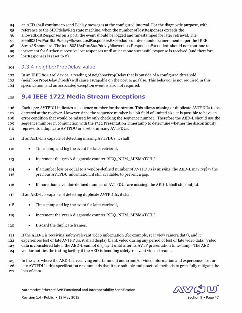
Automotive Ethernet AVB Functional and Interoperability Specification
Revision 1.4 - Public • 12 May 2015 Section 9 • Page 47
an AED shall continue to send Pdelay messages at the configured interval. For the diagnostic purpose, with 94
reference to the MDPdelayReq state machine, when the number of lostResponses exceeds the 95
allowedLostResponses on a port, the event should be logged and timestamped for later retrieval. The 96
ieee8021AsPortStatPdelayAllowedLostResponsesExceeded counter should be incremented per the IEEE 97
802.1AS standard. The ieee8021AsPortStatPdelayAllowedLostResponsesExceeded should not continue to 98
increment for further successive lost responses until at least one successful response is received (and therefore 99
lostResponses is reset to 0). 100
9.3.4 neighborPropDelay value 101
In an IEEE 802.1AS device, a reading of neighborPropDelay that is outside of a configured threshold 102
(neighborPropDelayThresh) will cause asCapable on the port to go false. This behavior is not required in this 103
specification, and an associated exception event is also not required. 104
9.4 IEEE 1722 Media Stream Exceptions 105
Each 1722 AVTPDU indicates a sequence number for the stream. This allows missing or duplicate AVTPDUs to be 106
detected at the receiver. However since the sequence number is a bit field of limited size, it is possible to have an 107
error condition that would be missed by only checking the sequence number. Therefore the AED-L should use the 108
sequence number in conjunction with the 1722 Presentation Timestamp to determine whether the discontinuity 109
represents a duplicate AVTPDU or a set of missing AVTPDUs. 110
If an AED-L is capable of detecting missing AVTPDUs, it shall 111
Timestamp and log the event for later retrieval, 112
Increment the 1722A diagnostic counter “SEQ_NUM_MISMATCH,” 113
If a number less or equal to a vendor-defined number of AVTPDUs is missing, the AED-L may replay the 114
previous AVTPDU information, if still available, to prevent a gap. 115
If more than a vendor-defined number of AVTPDUs are missing, the AED-L shall stop output. 116
If an AED-L is capable of detecting duplicate AVTPDUs, it shall 117
Timestamp and log the event for later retrieval, 118
Increment the 1722A diagnostic counter “SEQ_NUM_MISMATCH,” 119
Discard the duplicate frames. 120
If the AED-L is receiving safety-relevant video information (for example, rear view camera data), and it 121
experiences lost or late AVTPDUs, it shall display blank video during any period of lost or late video data. Video 122
data is considered late if the AED-L cannot display it until after its AVTP presentation timestamp. The AED 123
vendor notifies the testing facility if the AED is handling safety-relevant video streams. 124
In the case where the AED-L is receiving entertainment audio and/or video information and experiences lost or 125
late AVTPDUs, this specification recommends that it use suitable and practical methods to gracefully mitigate the 126
loss of data. 127

Automotive Ethernet AVB Functional and Interoperability Specification
Revision 1.4 - Public • 12 May 2015 Section 9 • Page 48
Under no conditions shall an AED-T send outdated data, which might have accumulated during an error 128
condition, into the network. Outdated data is defined here as any AVTPDU that cannot be sent such that it 129
reaches all listeners in time to be presented at its presentation timestamp. 130
131

Automotive Ethernet AVB Functional and Interoperability Specification
Revision 1.4 - Public • 12 May 2015 Section 10 • Page 49
10 Security 1
Due to the complexities related to automotive security in general and Ethernet security in particular, this section 2
is deferred to a later release of the document. 3
4

Automotive Ethernet AVB Functional and Interoperability Specification
Revision 1.4 - Public • 12 May 2015 Section 11 • Page 50
11 Content Protection 1
Content Protection provides cryptographic protection on copyrighted material as it traverses an AVB network. 2
System integrators and OEMs will supply specific requirements for AEDs in the area of content protection. For 3
reference on Content Protection on AVB traffic, please refer to Annex H in IEEE 1722a [1722a]. 4
5

Automotive Ethernet AVB Functional and Interoperability Specification
Revision 1.4 - Public • 12 May 2015 Section 12 • Page 51
12 Network Management 1
Deferred to a later release of this document. 2
3
Automotive Ethernet AVB Functional and Interoperability Specification
Revision 1.4 - Public • 12 May 2015 Section 13 • Page 52
13 Diagnostic Counters 1
Ethernet diagnostic counters are important to have in Ethernet devices in order to aid monitoring and diagnostics 2
of network performance and troubleshooting of networking faults. 3
This section discusses and defines requirements for diagnostic statistics for the following service layers: 4
Ethernet interfaces (PHY, MAC) 5
Ethernet Bridging 6
AVB Protocols 7
1722 Transport 8
Counters for higher service layers, such as TCP/IP or application level, are out of this document’s scope. 9
For the purposes of AVnu certification testing, the AED vendor shall provide a mechanism for accessing each 10
counter that it supports, and the format for returning the value of the counter. For all statistical counters 11
supported by an AED, the AED shall provide a read operation. 12
13.1 Ethernet Interfaces 13
Most available Ethernet hardware offers counters at the Physical or MAC service layers that offer insight to the 14
performance of the Ethernet interfaces on the device. These can be collected at many levels, including device, port, 15
priority queue and VLAN, and mostly count packets, both good and bad, of various types. Such counters are 16
standardized in the following specifications: 17
RFC 3635 – MIB for Ethernet-like Interface Types (see dot3StatsTable) 18
RFC 2819 – RMON MIB (see the Ethernet Statistics Group) 19
Because it is generally good practice to offer such statistics vendors of AED’s are encouraged to provide support 20
for them. However, AED’s are not required to support them. 21
13.2 Ethernet Bridging 22
RFC 4188 (Managed Objects for Bridges) specifies some standard statistics, but is mostly comprised of 23
configuration and status. Vendors of AED-B’s are encouraged to provide support for them. However, AED-B’s are 24
not required to support them. 25
13.3 AVB Protocols 26
The 802.1AS standard specifies the ieee8021AsPortStatIfTable in its MIB. All AED’s shall maintain the counters 27
in this table and make them available for certification testing. These counters include: 28
ieee8021AsPortStatRxSyncCount 29
Automotive Ethernet AVB Functional and Interoperability Specification
Revision 1.4 - Public • 12 May 2015 Section 13 • Page 53
ieee8021AsPortStatRxFollowUpCount 30
ieee8021AsPortStatRxPdelayRequest 31
ieee8021AsPortStatRxPdelayResponse 32
ieee8021AsPortStatRxPdelayResponseFollowUp 33
ieee8021AsPortStatRxAnnounce 34
ieee8021AsPortStatRxPTPPacketDiscard 35
ieee8021AsPortStatRxSyncReceiptTimeouts 36
ieee8021AsPortStatAnnounceReceiptTimeouts 37
ieee8021AsPortStatPdelayAllowedLostResponsesExceeded 38
ieee8021AsPortStatTxSyncCount 39
ieee8021AsPortStatTxFollowUpCount 40
ieee8021AsPortStatTxPdelayRequest 41
ieee8021AsPortStatTxPdelayResponse 42
ieee8021AsPortStatTxPdelayResponseFollowUp 43
ieee8021AsPortStatTxAnnounce 44
The ‘Announce’ related values are optional and should return zero where BMCA is not implemented. 45
13.4 1722 Transport 46
An AED-E shall support the counters listed in IEEE 1722a Annex E [1722a]. 47