Power Macintosh 4400/200 and 4400/200 PC Far East:...
132
Service Source K Power Macintosh 4400 Power Macintosh 4400/200 and 4400/200 PC Far East: Power Macintosh 7220/200 and 7220/200 PC Europe Only: Power Macintosh 4400/160
Transcript of Power Macintosh 4400/200 and 4400/200 PC Far East:...

Service Source
K
Power Macintosh 4400
Power Macintosh 4400/200 and 4400/200 PCFar East: Power Macintosh 7220/200 and 7220/200 PC
Europe Only: Power Macintosh 4400/160

Service Source
K
Basics
Power Macintosh 4400
Basics System Overview - 1
System Overview
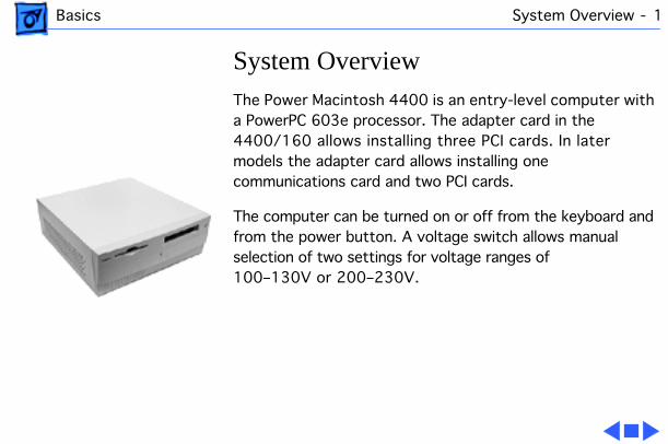
The Power Macintosh 4400 is an entry-level computer with a PowerPC 603e processor. The adapter card in the 4400/160 allows installing three PCI cards. In later models the adapter card allows installing one communications card and two PCI cards.
The computer can be turned on or off from the keyboard and from the power button. A voltage switch allows manual selection of two settings for voltage ranges of 100–130V or 200–230V.
Basics Power Macintosh 4400/200, 7220/200 - 2
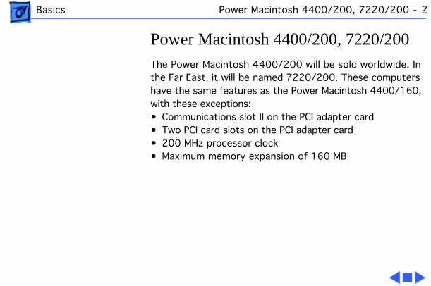
Power Macintosh 4400/200, 7220/200
The Power Macintosh 4400/200 will be sold worldwide. In the Far East, it will be named 7220/200. These computers have the same features as the Power Macintosh 4400/160, with these exceptions:• Communications slot II on the PCI adapter card• Two PCI card slots on the PCI adapter card• 200 MHz processor clock• Maximum memory expansion of 160 MB

Basics Voltage Switch - 3
Voltage Switch
The voltage switch must be set correctly to avoid damaging the computer. Insert a screw driver in the slot to set the switch to show “115” for voltages between 100 and 130. Set the switch to show “230” for voltages between 200 and 230. Some countries use two standardized voltages. If you aren’t sure which voltage is available, check with the electricity supply company before plugging in the computer.
Voltage Switch

Basics Voltage Switch - 4
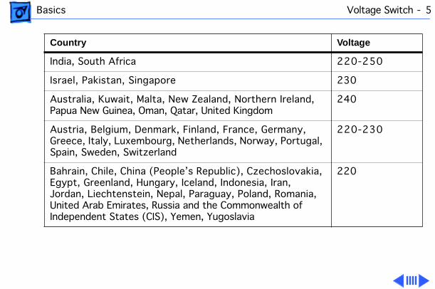
Here is a table listing voltages for some countries:
Country Voltage
Japan 100
South Korea 100 or 220
Jamaica, Taiwan 110
Peru 110 or 220
Brazil, Lebanon 110–220
Philippines 115
Bermuda, Canada, Puerto Rico, United States, Venezuela 120
Mexico 127
Saudi Arabia 127 or 220
Hong Kong 200
Basics Voltage Switch - 5
India, South Africa 220-250
Israel, Pakistan, Singapore 230
Australia, Kuwait, Malta, New Zealand, Northern Ireland, Papua New Guinea, Oman, Qatar, United Kingdom
240
Austria, Belgium, Denmark, Finland, France, Germany, Greece, Italy, Luxembourg, Netherlands, Norway, Portugal, Spain, Sweden, Switzerland
220-230
Bahrain, Chile, China (People’s Republic), Czechoslovakia, Egypt, Greenland, Hungary, Iceland, Indonesia, Iran, Jordan, Liechtenstein, Nepal, Paraguay, Poland, Romania, United Arab Emirates, Russia and the Commonwealth of Independent States (CIS), Yemen, Yugoslavia
220
Country Voltage
Basics Voltage Switch - 6
Caution:
Setting the correct voltage for the computer does not set the voltage for the monitor. To protect the monitor, be sure to use the appropriate adapter or voltage converter, if one is necessary.
Basics Key Commands - 7
Key Commands
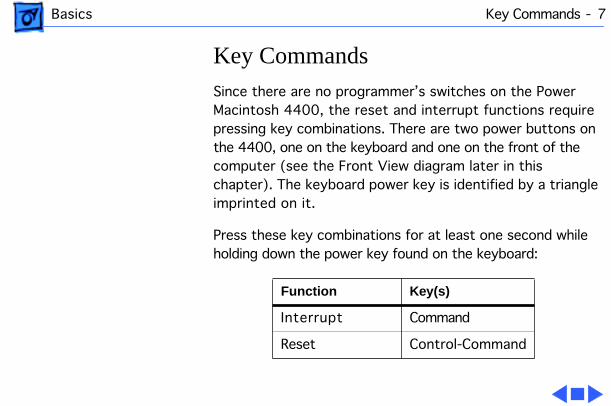
Since there are no programmer’s switches on the Power Macintosh 4400, the reset and interrupt functions require pressing key combinations. There are two power buttons on the 4400, one on the keyboard and one on the front of the computer (see the Front View diagram later in this chapter). The keyboard power key is identified by a triangle imprinted on it.
Press these key combinations for at least one second while holding down the power key found on the keyboard:
Function Key(s)
Interrupt Command
Reset Control-Command
Basics CD-ROM and Hard Drive Interface - 8
CD-ROM and Hard Drive Interface
The internal hard drive uses intelligent device electronics (IDE) technology, commonly used in DOS-compatible systems. The IDE drive uses the standard advanced technology attachment (ATA) or IDE interface. The IDE hard drive functions the same as a typical SCSI hard drive. You must replace IDE drives like for like. The IDE drive does not affect SCSI ID selections or SCSI termination schemes. Seven external SCSI devices may be daisy-chained through the external SCSI port.
The CD-ROM drive uses the advanced technology adapter peripheral interface (ATAPI), not SCSI. The ATA and ATAPI interface schemes could be incompatible with some disk utility programs.
Basics Peripheral Component Interconnect (PCI) Technology - 9
Peripheral Component Interconnect (PCI) Technology
The Power Macintosh 4400 offers peripheral component interconnect (PCI) expansion. Because the PCI bus is an industry standard, most existing PCI 2.0-compliant cards (with the addition of a Macintosh OS-specific software driver) will work in these computers.
PCI offers significantly higher performance than the NuBus architecture used in previous Macintosh models. Running at 33 MHz, the PCI bus is up to three times faster than NuBus, offering overall enhanced system performance, particularly in the areas of video and networking.
PCI expansion cards are mounted horizontally in an adapter card.

Basics Peripheral Component Interconnect (PCI) Technology - 10
Note:
The Power Macintosh PCI adapter card expansion slots are compatible with all PCI 2.0 specification-compliant cards with the addition of a Macintosh-OS-specific software driver. Nubus cards
cannot
be used in these expansion slots. PDS cards for the Macintosh LC family, the Macintosh Quadra 630 computer, or cards that operate in the I/O expansion slot in Power Macintosh 5200 and 6200 computers are
not
compatible with the PCI adapter card expansion slots.
Basics Dual In-Line Memory Modules (DIMMs) - 11
Dual In-Line Memory Modules (DIMMs)
The Power Macintosh 4400 uses DRAM on dual in-line memory modules (DIMMs). Three slots allow for memory expansion up to 96 MB using 3.3 V unbuffered 8-byte extended data output (EDO) JEDEC-standard 168-pin DRAM DIMM cards. DRAM expansion slot 1 only supports single-bank DIMMs. DRAM expansion slots 2 and 3 support both single-bank and dual-bank DIMMs. No DRAM is soldered on the logic board.
Important:
The single in-line memory modules (SIMMs) used in previous Macintosh models are
not
compatible with 4400 models.
Don’t
use DIMMs that support a 4K refresh rate. Use 168-pin, 3.3 V unbuffered EDO, 60 ns or faster DIMMs. Also, the JEDEC MO-161 specification shows three possible heights for the EDO DIMM. For Macintosh
Basics Dual In-Line Memory Modules (DIMMs) - 12
computers, use only the shortest of the three (1.100 inches). Taller DIMMs put excessive pressure on the DIMM sockets due to mechanical pressure inside the case.
The DIMMs can be installed one or more at a time. In the 4400/160 each DIMM slot can support up to a 32 MB bank of memory. In the 4400/200 and 7220/200, the first DIMM slot supports up to a 32 MB bank and the other two support up to 64 MB in each. The logic board supports only linear memory organization. The combined memory of all of the DIMMs installed will be configured as a contiguous memory space.

Basics Video RAM - 13
Video RAM
The logic board has a 120-pin video DIMM connector that allows the use of EDO RAM. The video controller supports the following for video memory:• 1 or 2 MB of EDO RAM • 1, 2, or 4 MB of SGRAM
PC Compatibility Cards
Apple computer offers PC Compatibility Card upgrade kits that bring full DOS functionality to the Power Macintosh 4400 computers. The cards plug into any available PCI slot on the logic board. Refer to the PC Compatibility Card manual on this Service Source CD for more information and installation instructions.

Basics GeoPort Technology - 14
GeoPort Technology
Geoport is a hardware and software communications architecture that has been optimized for computer-telephony integration. It has three main attributes:• It lets any GeoPort-compatible computer connect to any
telephone (analog or digital, public or private) anywhere in the world.
• Once connected, it supports an arbitrary number of independent data streams up to a total bandwidth of 2 MB/second.
• Unlike traditional asynchronous data communications (such as AppleTalk), GeoPort also supports isochronous data streams (such as real-time voice and video) and provides the real-time application program interfaces (APIs) necessary to hide the implementation details from both the recipient and the sender.

Basics Front View - 15
Front View
MouseKeyboard
CD-ROM Drive
Monitor
Hard Drive
Speaker
Floppy Drive
Computer
CD-ROM DriveOpen/Close Button
Power Key
Power Button
Basics Rear View - 16
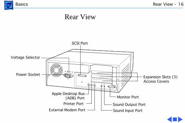
Rear View
Monitor Port
SCSI Port
Sound Output Port
Apple Desktop Bus(ADB) Port
Sound Input Port
Power Socket
External Modem Port
Printer Port
Expansion Slots (3)Access Covers
Voltage Selector

Basics Logic Board - 17
Logic Board
3 DRAM Slots
Power SupplySockets
PCI AdapterSlot
Processor withHeat Sink
L2 Cache Slot
ROM
Video DIMM Slot
Battery

Service Source
K
Specifications
Power Macintosh 4400
Specifications Processor - 1
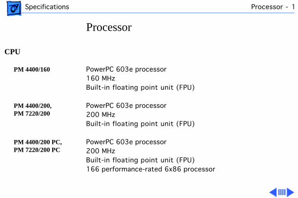
Processor
CPU
PM 4400/160
PowerPC 603e processor160 MHzBuilt-in floating point unit (FPU)
PM 4400/200, PM 7220/200
PowerPC 603e processor200 MHzBuilt-in floating point unit (FPU)
PM 4400/200 PC, PM 7220/200 PC
PowerPC 603e processor200 MHzBuilt-in floating point unit (FPU)166 performance-rated 6x86 processor
Specifications Processor - 2
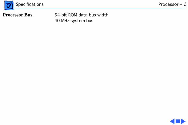
Processor Bus
64-bit ROM data bus width40 MHz system bus
Specifications Memory - 3
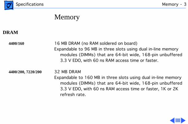
Memory
DRAM
4400/160
16 MB DRAM (no RAM soldered on board)Expandable to 96 MB in three slots using dual in-line memory
modules (DIMMs) that are 64-bit wide, 168-pin unbuffered 3.3 V EDO, with 60 ns RAM access time or faster.
4400/200, 7220/200
32 MB DRAMExpandable to 160 MB in three slots using dual in-line memory
modules (DIMMs) that are 64-bit wide, 168-pin unbuffered 3.3 V EDO, with 60 ns RAM access time or faster, 1K or 2K refresh rate.

Specifications Memory - 4
Video RAM
1 MB video EDO RAM DIMMExpandable to 4 MB with SGRAM DIMM
EDO DIMM 1 or 2 MBSGRAM DIMM 1, 2, or 4 MB
ROM
4 MB of read-only memory
PRAM
8K of nonvolatile parameter memory
Cache Memory
4400/160
Optional 256K Level 2 cache on a 160-pin DIMM card
4400/200, 7220/200
Optional 256K Level 2 cache DIMM

Specifications Disk Storage - 5
Disk Storage
Floppy Drive
1.4 MB Apple SuperDriveAccepts high-density 1.4 MB disks and 800K disksReads, writes, and formats Macintosh, Windows, MS-DOS, OS/2, and ProDOS disks
CD-ROM Drive
Advanced Technology Adapter Peripheral Interface (ATAPI) CD-ROM (8X-speed)
Hard Drive
4400/160
1.2 GB IDE hard drive
4400/200, 7220/200
2 GB IDE hard drive

Specifications I/O Interfaces - 6
I/O Interfaces
Apple Desktop Bus
One Apple Desktop Bus (ADB) port supporting up to three ADB input devices daisy-chained through a synchronous serial bus
Keyboard
Supports all Apple Desktop Bus (ADB) keyboards
Mouse
Supports all models of the ADB mouse
DMA I/O
10 DMA channels
Communications Expansion Slot (4400/200, 7220/200)
An Ethernet card or internal modem card may be installed in the bottom communications slot of the adapter card.

Specifications I/O Interfaces - 7
PCI Expansion
4400/160
Three industry-standard PCI expansion slots (45 watts combined power allowance for all three slots). Install only expansion cards that come with Macintosh drivers and are compliant with the PCI 2.0 standard. NuBus cards cannot be used in these expansion slots.
One internal expansion slot supports a full-size 12.28-inch 15-watt peripheral component interconnect expansion card.
All three internal expansion slots support 6.88-inch PCI expansion cards.
4400/200, 7220/200
Two industry-standard PCI expansion slots. Install only expansion cards that come with Macintosh drivers and are compliant with the PCI 2.0 standard. NuBus cards cannot be used in these expansion slots. One internal PCI expansion slot supports a 12.28-inch, 15-watt PCI card. Both internal PCI expansion slots support 6.88-inch PCI cards.
Specifications I/O Interfaces - 8
Video-out
Monitor port (15-pin SVGA compatible) supporting color and grayscale monitors of various sizes and resolutions. Depending on the amount of video RAM installed, the built-in video supports up to 800 x 600 pixel resolution at 16 bits per pixel and up to 1152 x 870 at 8 bits per pixel. Built-in 2D graphics acceleration.
Can connect to these monitors: Apple High Resolution RGB Monitor (13"), Macintosh Color Display (14"), Apple Basic Color Monitor (14"), Apple Color Plus 14" Display, Apple Multiple Scan 14 or Apple Multiple Scan 15 Displays, Apple 16" Display, Apple Multiple Scan 17 Display or Apple Multiple Scan 1705 Display, AppleVision 1710 Display, Apple 19" RGB Display, Apple Multiple Scan 20 Display, Apple 21" Color (two-page display).

Specifications I/O Interfaces - 9
Sound
16-bit stereo audio input and output—stereo in, stereo record, stereo out. Up to 44.1 KHz sampling rate.
Sound Output
One 3.5-mm sound output port for line-level devices such as powered loudspeakers.
Sound Input
One 3.5-mm sound input port for stereo sound input. The sound input port supports the Apple PlainTalk Microphone. In addition, the sound input port supports a standard stereo (miniplug-to-RCA) cable adapter for connecting stereo equipment to the computer. The port does not support the Apple Omni microphone (the round microphone shipped with some earlier models of Macintosh) or the attenuated RCA adapter provided with some models of Macintosh.

Specifications I/O Interfaces - 10
SCSI
One external standard SCSI port that supports up to seven external SCSI devices
Important:
Some older SCSI devices or SCSI devices not manufactured by Apple may require updated drivers. Contact the device manufacturer for information on obtaining driver software.
Serial
Two high-speed DMA RS-232/RS-422 serial ports. LocalTalk and GeoPort compatible.
GeoPort Telephony
Requires GeoPort telecom adapter28.8 Kbit/sec. modem supportV.17 fax supportGeoPort Fax and GeoPort Telephony software includedSpeakerphone and answering-machine capability

Specifications Electrical - 11
Electrical
Line Voltage
90–270 VACSwitchable 110/220 VAC, RMS single phase
Frequency
47–63 HzSingle phase
Power
200 W maximum, not including display
Energy Star
EPA Energy Star compliant

Specifications Physical - 12
Physical
Dimensions
Height: 5.43" (139 mm)Width: 15.12" (385 mm)Depth: 17.37" (442 mm)
Weight
24 lb. (9.5 kg)Weight varies depending on type of hard disk and any optional
equipment.
Specifications Environmental - 13
Environmental
Temperature
Operating: 50°–104° F (10°–40° C)Storage: -40° to 116.6° F (-40° to 47° C)Transient: -40° to 149° F (-40° to 65° C)
Humidity
Noncondensing, 20–95%
Altitude
0–10,000 ft. (0–3,048 m)
Service Source
K
Troubleshooting
Power Macintosh 4400

Troubleshooting General - 1
General
The Symptom Charts included in this chapter will help you diagnose specific symptoms related to your product. Because cures are listed on the charts in the order of most likely solution, try the first cure first. Verify whether or not the product continues to exhibit the symptom. If the symptom persists, try the next cure. (Note: If you have replaced a module, reinstall the original module before you proceed to the next cure.)
If you are not sure what the problem is, or if the Symptom Charts do not resolve the problem, refer to the Flowchart for the product family.
For additional assistance, contact Apple Technical Support.

Troubleshooting Symptom Charts/System - 2
Symptom Charts
System
System intermittently crashes or hangs
1 Verify that system software is version 7.5.3 or later.2 Verify that software is known-good.3 Verify that software is PowerPC-compatible (contact
developer).4 Clear parameter RAM. Hold down Command-Option-P-R
during startup, but before “Welcome to Macintosh” appears.5 Disconnect all external devices attached (except monitor)
and restart. 6 Replace DIMMs. 7 Replace logic board. Retain customer’s DIMMs.8 Replace power supply.

Troubleshooting Symptom Charts/System - 3
System
System does not start up
1 Reset logic board. Refer to Additional Procedures.2 Replace power supply.3 Replace logic board. Retain customer’s DIMMs.
System does not start up from keyboard, but starts up from power switch
1 Check keyboard connection.2 Verify keyboard as known-good.
System does not start up from power switch, but starts up from keyboard
1 Make sure power switch cable is properly plugged into logic board.
2 Check for cuts in power switch cable (especially near front under CD-ROM drive).

Troubleshooting Symptom Charts/System - 4
System
Front power switch LED does not light up
1 Check LED connection to logic board.2 Check polarity of LED connector on logic board. Triangle
should be over pin 1.3 Check cable for cuts (especially under CD-ROM drive).4 Replace LED harness.

Troubleshooting Symptom Charts/Audio - 5
Audio
Distorted or garbled sound
1 Check volume level.2 Check volume level in Monitor and Sound control panel.3 Check speaker for damage.
No sound output from speaker
1 Check speaker connection to logic board.2 Attach headphones. If you hear sound through headphones,
replace speaker assembly.3 Replace speaker assembly.

Troubleshooting Symptom Charts/Video - 6
Video
No video, fan is running
1 Check monitor connection.2 Try known-good monitor.3 Remove all DRAM DIMMs and try replacing them one at a
time to test. Replace any bad DIMMs.4 Replace logic board. Retain customer’s DIMMs.5 Replace power supply.
After restarting, two connected monitors, used for video mirroring, appear black or gray
Note:
This issue only affects early European Power Macintosh 4400 systems.
Unplug monitor cable connected to PCI video card and restart.
Or, if user wants to continue video mirroring, instruct to turn off video mirroring in Monitors & Sounds control panel before shutting down or restarting. Turn video mirroring on after starting computer.

Troubleshooting Symptom Charts/Floppy Drive - 7
Floppy Drive
Audio and video are present, but internal floppy drive does not operate
1 Replace bad disk with known-good disk.2 Make sure cable is connected to logic board.3 Replace floppy drive.4 Replace cable connecting to the logic board.5 Replace logic board. Retain customer’s DIMMs.
Disk ejects; display shows icon with blinking “X”
1 Replace bad system disk with known-good system disk.2 Replace floppy drive.3 Replace logic board. Retain customer’s DIMMs.
Disk does not insert all the way
1 Eject previously inserted disk by inserting opened paper clip into hole beside floppy drive.
2 Switch off system and hold mouse button down while switching system on (to complete eject cycle).
3 Replace floppy drive.

Troubleshooting Symptom Charts/Floppy Drive - 8
Floppy Drive
Disk does not eject 1 Insert opened paper clip into hole beside floppy drive.2 Switch off system and hold mouse button down while
switching system on (to complete eject cycle).3 Replace floppy drive.
Internal floppy drive runs continuously
1 Replace bad disk with known-good disk.2 Replace floppy drive.3 Replace logic board. Retain customer’s DIMMs.

Troubleshooting Symptom Charts/Hard Drive - 9
Hard Drive
Internal or external hard drive does not spin up
1 Verify that all hard drive connections are secure.2 Reseat logic board.3 Replace internal IDE hard drive.4 Replace logic board. Retain customer’s DIMMs.
Internal hard drive runs continuously
1 Verify that system software is version 7.5.3 or later.2 Replace hard drive cable.3 Replace internal hard drive.4 Replace logic board. Retain customer’s DIMMs.
Hard drive not found when booted from CD-ROM drive
Use Drive Setup to attempt to recognize or mount hard drive.

Troubleshooting Symptom Charts/Hard Drive - 10
Hard Drive
Hard drive not recognized
1 Make sure CD-ROM interface cable is connected.
Note:
This IDE bus termination issue only affects early European Power Macintosh 4400 systems.
2 Make sure hard drive cables are securely connected.

Troubleshooting Symptom Charts/CD-ROM Drive - 11
CD-ROM Drive
CD-ROM drive does not accept disc
1 If compact disc is dirty or damaged, use known-good compact disc.
2 Replace CD-ROM drive.
Volume control does not operate correctly when playing audio CD, but does work when playing system sounds
Check Monitor and Sound control panel setting.
Computer cannot mount known-good CD-ROM discs
1 Check that CD-ROM drive software is installed correctly.2 Check power and signal cable connections.3 Replace CD-ROM drive.

Troubleshooting Symptom Charts/Peripheral - 12
Peripheral
Cursor does not move 1 Restart system.2 Check mouse connection.3 If mouse was connected to keyboard, connect mouse to rear
ADB port and disconnect keyboard. If mouse works, replace keyboard.
4 If mouse does not work in ADB port, replace mouse.5 Reseat logic board.6 Replace logic board. Retain customer’s DIMMs.
Cursor moves, but when you click the mouse, nothing happens
1 Replace mouse.2 Reseat logic board.3 Replace logic board. Retain customer’s DIMMs.

Troubleshooting Symptom Charts/Peripheral - 13
Peripheral
Cannot double-click mouse to open application, disk, or server
1 Check mouse speed on Mouse control panel.2 Unplug battery from logic board, wait 20 seconds, plug in
battery, and restart computer.3 If mouse was connected to keyboard, connect mouse to rear
ADB port and disconnect keyboard. If mouse works, replace keyboard.
4 If mouse does not work in ADB port, replace mouse.5 Replace logic board. Retain customer’s DIMMs.
No response to any key on keyboard
1 Verify that system software is version 7.5.3 or later. 2 Check keyboard connection to ADB port.3 Replace keyboard.4 Reseat logic board. 5 Replace logic board. Retain customer’s DIMMs.

Troubleshooting Symptom Charts/Peripheral - 14
Peripheral
Known-good StyleWriter does not print
1 Verify that Chooser is set correctly.2 Verify that printer driver and system software are not
corrupt.3 Verify system software is version 7.5.3 or later.4 Replace printer interface cable.5 Replace logic board. Retain customer’s DIMMs.
Known-good LaserWriter does not print
1 Verify that Chooser is set correctly.2 Verify that printer driver and system software are not
corrupt.3 Verify system is properly connected to printer.

Troubleshooting Symptom Charts/Miscellaneous - 15
Miscellaneous
No audio, and no drive operation
1 Connect power cable.2 Switch power on.3 Replace power cable.4 Replace logic board. Retain customer’s DIMMs.
“Sad Macintosh” icon 1 Start up from known-good disk. 2 Replace DIMMs. 3 Replace logic board. Retain customer’s DIMMs.
Troubleshooting Symptom Charts/Miscellaneous - 16
Miscellaneous
Screen shows “Sad Macintosh” icon and black vertical lines; screeching sound
1 Replace DIMMs. 2 Replace logic board. Retain customer’s DIMMs.
Headphone jack does not operate correctly
Verify that headphone jack is seated properly.
Service Source
K
Take Apart
Power Macintosh 4400

Take Apart Top Housing - 1
Top Housing
No preliminary steps are required before you begin this procedure.
Caution:
Review the ESD precautions in Bulletins/Safety.
Take Apart Top Housing - 2
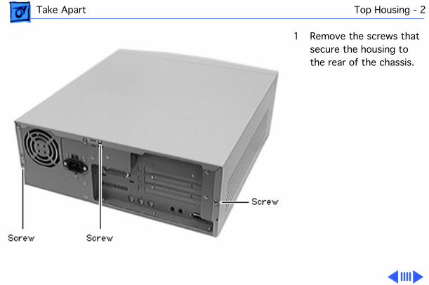
1 Remove the screws that secure the housing to the rear of the chassis.
Take Apart Top Housing - 3
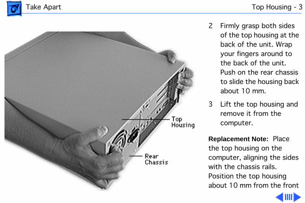
2 Firmly grasp both sides of the top housing at the back of the unit. Wrap your fingers around to the back of the unit. Push on the rear chassis to slide the housing back about 10 mm.
3 Lift the top housing and remove it from the computer.
Replacement Note:
Place the top housing on the computer, aligning the sides with the chassis rails. Position the top housing about 10 mm from the front

Take Apart Top Housing - 4
panel. Slide the top housing forward until it fits into place. If the lid doesn’t fit properly, check the link bar to be sure it is installed correctly. Also, if the floppy/CD-ROM drive carrier was removed, make sure the carrier hooks correctly into the bottom of the chassis. Replace the rear screws.

Take Apart Link Bar - 5
Link Bar
Before you begin, remove the top housing.
Caution:
Review the ESD precautions in Bulletins/Safety.
Take Apart Link Bar - 6
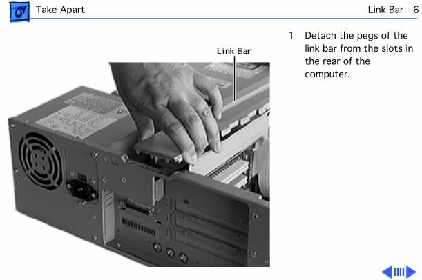
1 Detach the pegs of the link bar from the slots in the rear of the computer.
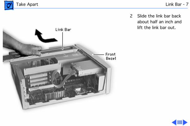
Take Apart Link Bar - 7
2 Slide the link bar back about half an inch and lift the link bar out.

Take Apart Link Bar - 8
Replacement Note:
To replace the link bar, position the bar so that it firmly holds the PCI adapter board and disk drive carriers. Slide the link bar toward the front panel until it fits into place. The three hooks at the bottom of the link bar must catch the floppy/CD-ROM drive carrier. If it doesn’t fit correctly after the floppy/CD-ROM drive carrier was removed, make sure the carrier was installed correctly.
Press the rear of the bar to
Take Apart Link Bar - 9
lock the pegs into the slots in the rear of the chassis.

Take Apart Front Bezel - 10
Front Bezel
Before you begin, remove the following:• Top housing• Link bar
Caution:
Review the ESD precautions in Bulletins/Safety.
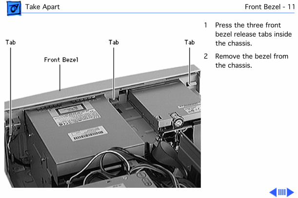
Take Apart Front Bezel - 11
1 Press the three front bezel release tabs inside the chassis.
2 Remove the bezel from the chassis.

Take Apart Front Bezel - 12
Replacement Note:
Insert the three tabs at the front base of the chassis. Snap the release tabs into place.

Take Apart Cache Card - 13
Cache Card
Before you begin, remove the top housing.
Note:
Do not touch the connectors. Handle only by the edges.
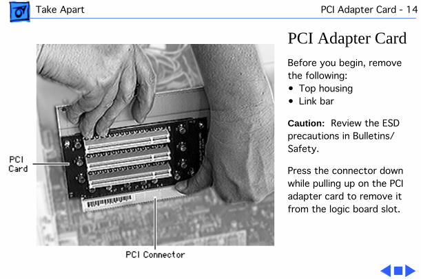
Take Apart PCI Adapter Card - 14
PCI Adapter Card
Before you begin, remove the following:• Top housing• Link bar
Caution:
Review the ESD precautions in Bulletins/Safety.
Press the connector down while pulling up on the PCI adapter card to remove it from the logic board slot.
Take Apart Hard Drive Carrier - 15
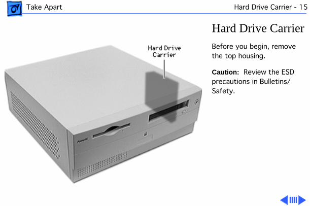
Hard Drive Carrier
Before you begin, remove the top housing.
Caution:
Review the ESD precautions in Bulletins/Safety.

Take Apart Hard Drive Carrier - 16
1 Lift up the hard drive carrier to detach it from the hooks on the floppy/CD-ROM drive carrier.

Take Apart Hard Drive Carrier - 17
2 Disconnect the power and data cables attached to the hard drive.

Take Apart Hard Drive Carrier - 18
Caution:
Cables can catch on the exposed hooks and become damaged.
Replacement Note:
Place the hard drive carrier on the hooks that attach it to the floppy/CD-ROM drive carrier.

Take Apart Hard Drive - 19
Hard Drive
Before you begin, remove the following:• Top housing• Hard drive carrier
Caution:
Review the ESD precautions in Bulletins/Safety.

Take Apart Hard Drive - 20
1 Remove the four screws that secure the hard drive to the hard drive carrier.
2 Remove the hard drive from the carrier.
Replacement Note:
Position the hard drive on the hard drive carrier. Replace the four screws to secure the hard drive to the carrier. Connect the hard drive cables to the hard drive. Place the hard drive carrier on the hooks that attach it to the floppy/CD-ROM drive carrier.

Take Apart Floppy/CD-ROM Drive Carrier - 21
Floppy/CD-ROM Drive Carrier
Before you begin, remove the following:• Top housing• Link bar• Front bezel• Hard drive carrier• PCI adapter card
Caution:
Review the ESD precautions in Bulletins/Safety.

Take Apart Floppy/CD-ROM Drive Carrier - 22
1
Note:
Press the plastic release tab on the audio tab to remove it.
Disconnect the audio, data, and power cables from the CD-ROM drive.

Take Apart Floppy/CD-ROM Drive Carrier - 23
2 Disconnect the data cable from the floppy drive.
3 Pull the floppy/CD-ROM drive carrier about 1 cm away from the front panel and toward the CD-ROM drive to avoid catching the metal hook under the logic board.

Take Apart Floppy/CD-ROM Drive Carrier - 24
4 Lift the carrier out of the computer.

Take Apart Floppy/CD-ROM Drive Carrier - 25
Replacement Note:
Be sure the power button and LED wires are firmly held under the clips and clear of the floppy/CD-ROM carrier path. These wires are easily cut when the drive carrier slides across them. Also pull the power supply wires out of the way. Guide the CD-ROM drive under the metal spring tabs at the top of the opening in front of the chassis. Align the carrier with the metal tabs at the base of the chassis and slide the carrier toward the chassis front until it fits into
Take Apart Floppy/CD-ROM Drive Carrier - 26
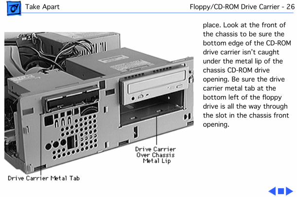
place. Look at the front of the chassis to be sure the bottom edge of the CD-ROM drive carrier isn’t caught under the metal lip of the chassis CD-ROM drive opening. Be sure the drive carrier metal tab at the bottom left of the floppy drive is all the way through the slot in the chassis front opening.

Take Apart CD-ROM Drive - 27
CD-ROM Drive
Before you begin, remove the following:• Top housing• Link bar• PCI adapter card• Front bezel• Hard drive carrier• Floppy/CD-ROM drive
carrier
Caution:
Review the ESD precautions in Bulletins/Safety.

Take Apart CD-ROM Drive - 28
1
Note:
A long-neck Phillips screw driver will make it easier to remove the CD-ROM screws under the floppy carrier.
Remove the four screws that secure the CD-ROM drive to the floppy/CD-ROM drive carrier.
2 Remove the CD-ROM drive from the carrier.
Take Apart CD-ROM Drive - 29
Replacement Note:
Position the CD-ROM drive on the drive bay. Replace the screws on both sides of the CD-ROM drive to secure it to the carrier. Replace the drive carrier in the computer, aligning the carrier with the tabs at the base of the housing. Fasten the hard drive carrier on the hooks on the side of the floppy/CD-ROM drive carrier. Connect the CD-ROM drive cables.

Take Apart Floppy Drive - 30
Floppy Drive
Before you begin, remove the following:• Top housing• Link bar• Front bezel• PCI adapter card• Hard drive carrier• Floppy/CD-ROM drive
carrier
Caution:
Review the ESD precautions in Bulletins/Safety.

Take Apart Floppy Drive - 31
1 Remove the four screws under the floppy drive bay that secure the Apple SuperDrive to the floppy/CD-ROM drive carrier.
2 Remove the Apple SuperDrive from the carrier.
Replacement Note:
Position the floppy drive on the bay of the carrier. Replace the four screws that secure the floppy drive to the carrier. Replace the drive carrier in the chassis aligning the carrier with the tabs at the

Take Apart Floppy Drive - 32
base of the housing. Fasten the hard drive carrier on the hooks on the side of the floppy/CD-ROM drive carrier. Connect the floppy drive cables.
Take Apart Logic Board - 33
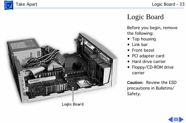
Logic Board
Before you begin, remove the following:• Top housing• Link bar• Front bezel• PCI adapter card• Hard drive carrier• Floppy/CD-ROM drive
carrier
Caution:
Review the ESD precautions in Bulletins/Safety.

Take Apart Logic Board - 34
1
Note:
Press the release tab of the soft-power connector to remove it. Grasp the plastic connector (not the wires) when removing the CD audio cable.
Disconnect all cables from the logic board. Refer to the logic board diagram at the end of this section.
Take Apart Logic Board - 35
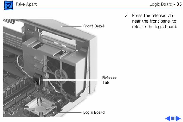
2 Press the release tab near the front panel to release the logic board.

Take Apart Logic Board - 36
3 Raise up the front of the logic board and pull the external ports out of the access holes in the rear of the chassis. Guide the logic board away from the power supply.
Replacement Note:
Gently pull the power switch and speaker cables into the opening over the speaker/fan assembly to keep the wires from being covered by the logic board. Tilt the logic board up slightly to insert the external ports on the logic board into the access

Take Apart Logic Board - 37
holes in the back of the chassis. Lower the front of the logic board so that the pegs in the housing base fit into the logic board holes. Press the front edge of the logic board down until the release tab clicks. Connect all cables to the proper sockets on the logic board. (See the diagram on the next page. Two 4-pin connectors from the power supply have no sockets, and will remain unconnected.) The LED connector must be plugged in so that the arrow goes over pin 1 on the logic

Take Apart Logic Board - 38
board.

Take Apart Logic Board - 39
Power Supply Soft Power
SCSIPower Supply
PCI AdapterSlot
Speaker
LED
Fan
Cable Connection Slots
Front BezelPower Switch
IDE HardDrive
CD-ROMAudio
IDE ATAPICD-ROM Drive
Floppy Drive

Take Apart Power Supply - 40
Power Supply
Before you begin, remove the following:• Top housing• Link bar• Hard drive carrier
Caution:
Review the ESD precautions in Bulletins/Safety.

Take Apart Power Supply - 41
1
Note:
Press the release tab of the soft-power connector to remove it.

Take Apart Power Supply - 42
Disconnect the five power supply cables from the logic board sockets.
Take Apart Power Supply - 43
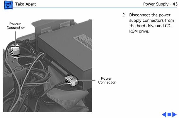
2 Disconnect the power supply connectors from the hard drive and CD-ROM drive.

Take Apart Power Supply - 44
3 Remove the 4 screws that secure the power supply to the rear of the chassis.
Take Apart Power Supply - 45
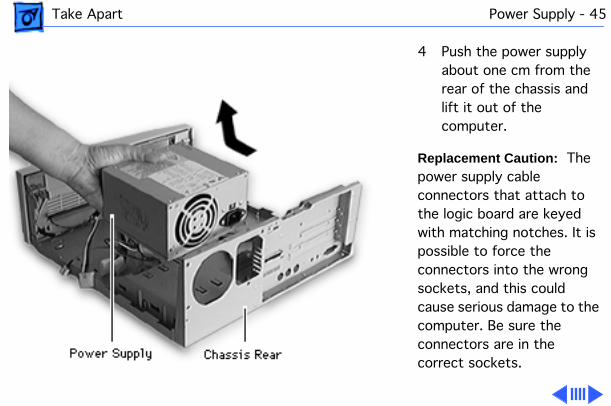
4 Push the power supply about one cm from the rear of the chassis and lift it out of the computer.
Replacement Caution:
The power supply cable connectors that attach to the logic board are keyed with matching notches. It is possible to force the connectors into the wrong sockets, and this could cause serious damage to the computer. Be sure the connectors are in the correct sockets.

Take Apart SCSI Cable - 46
SCSI Cable
Before you begin, remove the following:• Top housing• Link bar• PCI adapter card
Caution:
Review the ESD precautions in Bulletins/Safety.

Take Apart SCSI Cable - 47
1 Remove the two hex nuts that secure the SCSI cable to the rear of the chassis.

Take Apart SCSI Cable - 48
2 Disconnect the SCSI cable from the logic board.
3 Remove the SCSI cable from inside the chassis.

Service Source
K
Upgrades
Power Macintosh 4400

Upgrades DRAM DIMM - 1
DRAM DIMM
Before you begin, remove the following:• Top housing• Link bar• PCI adapter card
Caution:
Review the ESD precautions in Bulletins/Safety.
Note:
The DRAM sockets are located behind the PCI adapter card that supports the PCI cards in the computer.
DRAM Slot #3
DRAM Slot #2
DRAM Slot #1
Upgrades DRAM DIMM - 2
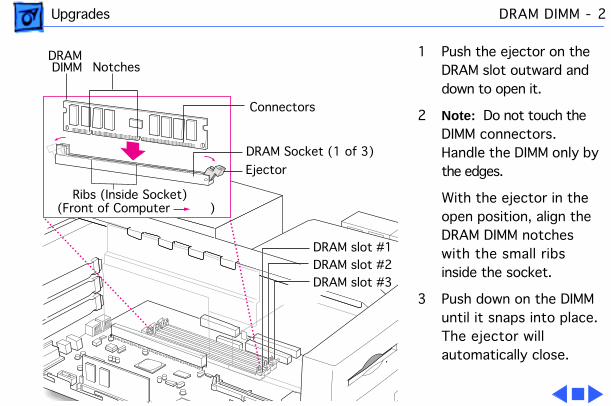
1 Push the ejector on the DRAM slot outward and down to open it.
2
Note:
Do not touch the DIMM connectors. Handle the DIMM only by the edges.
With the ejector in the open position, align the DRAM DIMM notches with the small ribs inside the socket.
3 Push down on the DIMM until it snaps into place. The ejector will automatically close.
DRAM DIMM
Ejector
Connectors
Notches
DRAM Socket (1 of 3)
(Front of Computer )Ribs (Inside Socket)
DRAM slot #3DRAM slot #2DRAM slot #1
Upgrades Video RAM DIMM - 3
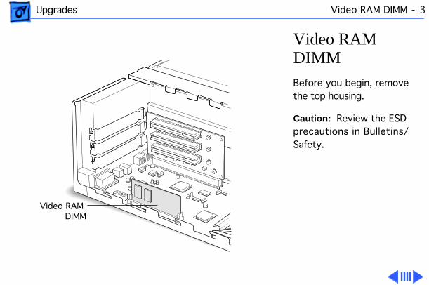
Video RAM DIMM
Before you begin, remove the top housing.
Caution:
Review the ESD precautions in Bulletins/Safety.
Video RAM DIMM

Upgrades Video RAM DIMM - 4
1
Note:
Do not touch the video RAM DIMM connectors. Handle only by the edges.
Align the notches in the video RAM DIMM with the small ribs inside the module slot, and insert the module into the slot.
2 Push down on the DIMM until it snaps into place.
VideoRAM DIMM Notch
Connectors
VideoRAM
DIMM Socket Front of Computer
Rib (Inside Socket)
Upgrades Cache Card - 5
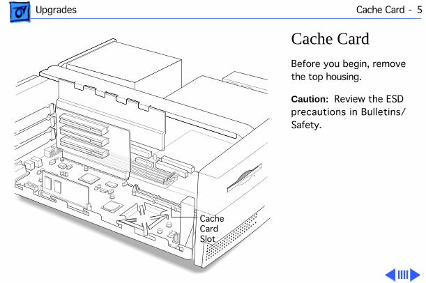
Cache Card
Before you begin, remove the top housing.
Caution:
Review the ESD precautions in Bulletins/Safety.
CacheCard Slot

Upgrades Cache Card - 6
Note:
The cache card is designed to fit into the slot only one way.
Note:
Do not touch the connectors. Handle only by the edges.
Align the notches in the cache card with the small ribs inside the card slot, and insert the card into the slot.
Cache Card Socket
Cache Card
Connectors
Notches
Front of Computer Ribs (Inside Socket)

Upgrades PCI Card - 7
PCI Card
Before you begin, remove the top housing.
Caution:
Review the ESD precautions in Bulletins/Safety.
Note:
A 6.88-inch card fits in all three slots of a Power Macintosh 4400/160. A 6.88-inch card fits in the top two slots of the Power Macintosh 4400/200 and 7220/200. A 12-inch card fits in the middle slot only.
PCI Slots (3)
Upgrades PCI Card - 8
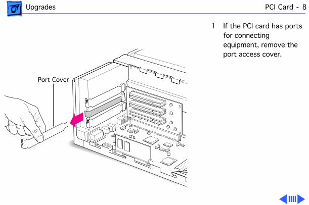
1 If the PCI card has ports for connecting equipment, remove the port access cover.
Port Cover
Upgrades PCI Card - 9
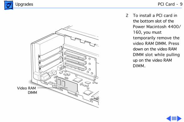
2 To install a PCI card in the bottom slot of the Power Macintosh 4400/160, you must temporarily remove the video RAM DIMM. Press down on the video RAM DIMM slot while pulling up on the video RAM DIMM.
Video RAM DIMM
Upgrades PCI Card - 10
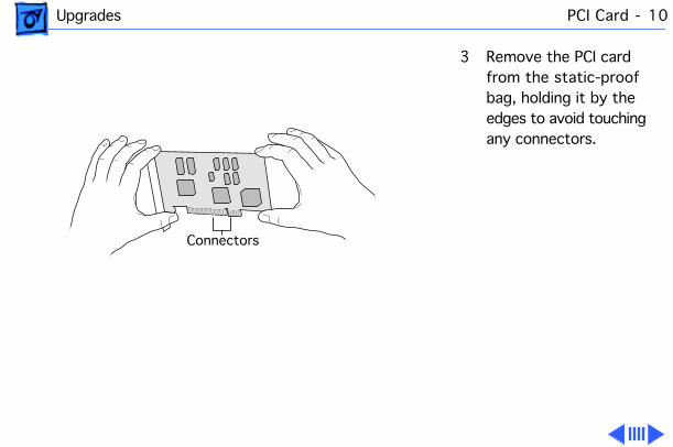
3 Remove the PCI card from the static-proof bag, holding it by the edges to avoid touching any connectors.
Connectors

Upgrades PCI Card - 11
4 Insert the PCI card into the PCI slot, aligning any ports on the card with the port access opening. Press the card firmly into the slot.
PCI Slot
Card Fence

Upgrades PCI Card - 12
5 Reinstall the screw removed from the port access cover.
6 If you removed the video RAM DIMM, reinstall it.
Screw

Upgrades Communications Card - 13
Communications Card
Before you begin, remove the top housing.
Caution:
Review the ESD precautions in Bulletins/Safety.
Note:
A communications card can only be installed in the bottom slot of the adapter card in a Power Macintosh 4400/200 or 7220/200. An Ethernet or internal modem card may be installed here. If a customer
CommunicationsCard Port
CommunicationsCard Slot

Upgrades Communications Card - 14
wants both Ethernet and internal modem cards, install an Ethernet PCI card in one of the upper slots and install the modem card in the lower communications slot.
Note:
Some communica-tions cards are not compatible. Look at the placement of the notches on the card, and use this illustration to help identify a compatible card.
Communications CardNotches
Notches
Notches
Communications Slot
Compatible
Compatible
Not compatible
Logic Board Fence
Logic Board(Side View)

Upgrades Communications Card - 15
1
Note:
You may need to temporarily remove the video RAM DIMM.
To remove the video RAM DIMM, press down on the video RAM DIMM slot while pulling up on the video RAM DIMM.
2 Remove the communications card from its static-proof bag, and hold the card by its edges to avoid touching the connectors.Video RAM DIMM

Upgrades Communications Card - 16
3 If the card has a hook, be sure it engages the hole in the access cover.
Communications Card Slot
Communications Card
Communications CardAccess Cover
Communications Card Hook

Upgrades Communications Card - 17
4 If the card doesn’t have a hook, pass the external connector through the opening in the access cover.
5 Insert the card into the communications slot. If it meets resistance, pull the card out and reinsert the connector. Press solidly into place.
6 Check the connection by lifting the card gently. If it resists and stays in place, it is solidly connected.
Communications Card Slot
Communications Card

Upgrades Communications Card - 18
7 If you removed the video RAM DIMM, replace it following the steps in the “Video RAM DIMM” section of this chapter.
Note:
Communications software may need to be installed for the card to work. Also, for an Ethernet card, the network connection in the AppleTalk control panel may need to be changed. See the manual that came with the card.

Upgrades PC Compatibility Cards - 19
PC Compatibility Cards
For information about these cards and installation instructions, refer to the PC Compatiblity Card manual on this Service Source CD.
Service Source
K
Additional Procedures
Power Macintosh 4400

Additional Procedures Battery Verification - 1
Battery Verification
Before you begin, remove the following:• Top housing• Link bar• Hard drive carrier• Floppy/CD-ROM drive
carrier
Caution:
Review the ESD precautions in Bulletins/Safety.
Additional Procedures Battery Verification - 2
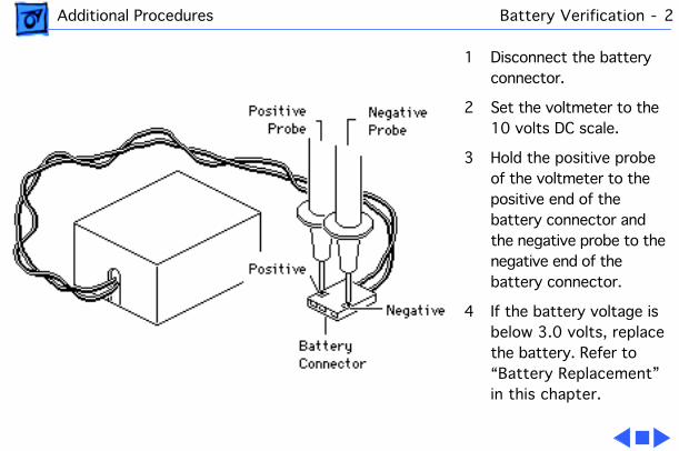
1 Disconnect the battery connector.
2 Set the voltmeter to the 10 volts DC scale.
3 Hold the positive probe of the voltmeter to the positive end of the battery connector and the negative probe to the negative end of the battery connector.
4 If the battery voltage is below 3.0 volts, replace the battery. Refer to “Battery Replacement” in this chapter.
Additional Procedures Battery Replacement - 3
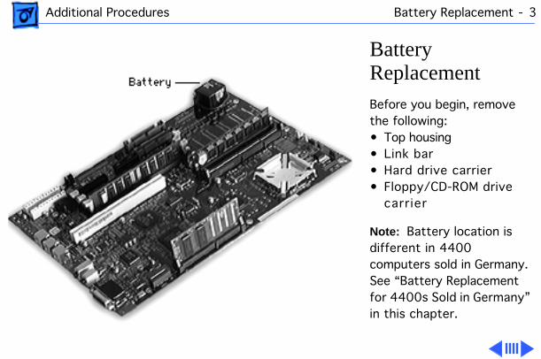
Battery Replacement
Before you begin, remove the following:• Top housing• Link bar• Hard drive carrier• Floppy/CD-ROM drive
carrier
Note:
Battery location is different in 4400 computers sold in Germany. See “Battery Replacement for 4400s Sold in Germany” in this chapter.

Additional Procedures Battery Replacement - 4
Caution:
Review the ESD precautions in Bulletins/Safety.
1 Pull up and disconnect the connector.
2 Pull up and remove the battery from its hook-and-loop base.
3 Install the new battery.

Additional Procedures Logic Board Reset - 5
Logic Board Reset
Before you begin, remove the following:• Top housing• Link bar• Hard drive carrier• Floppy/CD-ROM drive
carrier
Caution:
Review the ESD precautions in Bulletins/Safety.
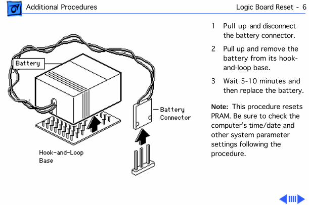
Additional Procedures Logic Board Reset - 6
1 Pull up and disconnect the battery connector.
2 Pull up and remove the battery from its hook-and-loop base.
3 Wait 5-10 minutes and then replace the battery.
Note:
This procedure resets PRAM. Be sure to check the computer’s time/date and other system parameter settings following the procedure.

Additional Procedures Logic Board Reset - 7
Note:
If this procedure resolves the problem, claim an adjustment on an SRO. If not, replace any defective parts and
do not
claim the adjustment.

Additional Procedures Battery Replacement for 4400s Sold in Germany - 8
Battery Replacement for 4400s Sold in Germany
Before you begin, remove the following:• Top housing• Link bar• Cache card
1 Using needle-nose pliers, pull up and disconnect the battery connector.

Additional Procedures Battery Replacement for 4400s Sold in Germany - 9
2 Pull up and twist to remove the battery from its hook-and-loop base.
3 Install the new battery and attach the battery connector.

Additional Procedures Battery Replacement for 4400s Sold in Germany - 10
4 Press the reset switch on the logic board using a flat plastic tool.

Service Source
K
Exploded View
Power Macintosh 4400
Exploded View 1
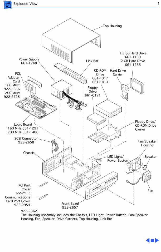
Power Supply661-1248
PCI Adapter
Card160 MHz:
922-2656200 MHz:
922-2725
Logic Board160 MHz 661-1291200 MHz 661-1408
SCSI Connector922-2658
Chassis
Fan
Speaker
Floppy Drive/CD-ROM DriveCarrier
Front Bezel922-2657
922-2862The Housing Assembly includes the Chassis, LED Light, Power Button, Fan/Speaker Housing, Fan, Speaker, Drive Carriers, Top Housing, Link Bar
LED Light/Power Button
Fan/SpeakerHousing
FloppyDrive
661-0121
CD-ROMDrive
661-1317661-1413
Hard DriveCarrier
1.2 GB Hard Drive661-1139
2 GB Hard Drive661-1255
Link Bar
Top Housing
Computer
ClockBattery
RAYOVAC
PCI PortCover
922-2953Communications Card Port Cover
922-2954