Power HT+ - hydroheat.com.au
42
Power HT+
Transcript of Power HT+ - hydroheat.com.au
Power HT+
2
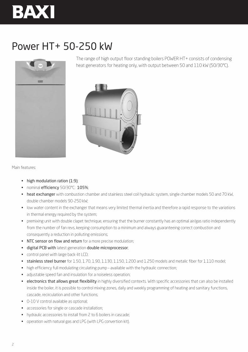
Main features:
• high modulation ration (1:9);
• nominal efficiency 50/30°C: 105%;
• heat exchanger with combustion chamber and stainless steel coil hydraulic system, single chamber models 50 and 70 kW,
double chamber models 90-250 kW;
• low water content in the exchanger that means very limited thermal inertia and therefore a rapid response to the variations
in thermal energy required by the system;
• premixing unit with double clapet technique, ensuring that the burner constantly has an optimal air/gas ratio independently
from the number of fan revs, keeping consumption to a minimum and always guaranteeing correct combustion and
consequently a reduction in polluting emissions;
• NTC sensor on flow and return for a more precise modulation;
• digital PCB with latest generation double microprocessor;
• control panel with large back-lit LCD;
• stainless steel burner for 1.50, 1.70, 1.90, 1.130, 1.150, 1.200 and 1.250 models and metalic fiber for 1.110 model;
• high efficiency full modulating circulating pump – available with the hydraulic connection;
• adjustable speed fan and insulation for a noiseless operation;
• electronics that allows great flexibility in highly diversified contexts. With specific accessories that can also be installed
inside the boiler, it is possible to control mixing zones, daily and weekly programming of heating and sanitary functions,
cascade, recirculation and other functions;
• 0-10 V control available as optional;
• accessories for single or cascade installation;
• hydraulic accessories to install from 2 to 6 boilers in cascade;
• operation with natural gas and LPG (with LPG convertion kit).
Power HT+ 50-250 kWThe range of high output floor standing boilers POWER HT+ consists of condensing heat generators for heating only, with output between 50 and 110 kW (50/30°C).

3
Power HT+
Heating onlyPower HT+ 1.50 1.70 1.90 1.110 1.130 1.150 1.200 1.250Maximum heat input (heating) kW 46,3 66,9 87,4 104,9 123,8 143 191 240
Minimum heat output kW 5,1 7,4 9,7 11,7 24,8 28,6 31,8 40
Rated heat output (80/60°C) Prated kW 45 65 85 102 121,5 140,3 185,9 232,8
Minimum heat output (80/60°C) kW 5 7,2 9,4 11,4 24,3 28,1 31 38,8
Maximum heat output (50/30°C) kW 48,6 70,2 91,8 110,2 130,6 150,9 200 250
Minimum heat output (50/30°C) kW 5,4 7,8 10,2 12,3 26,2 30,2 33,1 41,7
Useful heat output at 30% of rated heat output and low temperature regime** P1
kW 15 21,7 28,3 34 40,4 46,6 36 46
Seasonal space heating energy efficiency class A A - - - - - -
Efficiency Pn (lower calorific value) - Average temperature 70°C % 97,4 97,2 97,3 97,2 98,1 98,1 97,32 97,02
Efficiency at 30% (lower calorific value) - Return temperature 30°C % 108,4 108,1 108,2 108,1 108,5 108,5 109,1 109,1
Useful efficiency at rated heat output and high temperature regime* ŋ4 % 87,7 87,6 87,7 87,6 88,4 88,4 87,7 87,4
Useful efficiency at 30% of rated heat output and low temperature regime** ŋ1 % 97,7 97,4 97,5 97,4 97,8 97,8 98,3 98,3
Seasonal space heating energy efficiency ŋs % 93 93 93 93 93 93 94 94
NOx emissions mg/kWh 27 31 36 22 17 23 37 39
Maximum pressure heating circuit bar 4 4 4 4 6 6 6 6
Maximum inlet temperature heating circuit °C 85 85 85 85 85 85 85 85
Heating temperature range °C 25-80 25-80 25-80 25-80 25-80 25-80 25-80 25-80
Water content l 2,81 4,98 8,34 9,83 10 11 13 15
Dual flue system mm 80 80 110 110 110 110 150 150
Maximum flue mass flow rate kg/s 0,075 0,111 0,144 0,169 0,201 0,23 0,322 0,411
Minimum flue mass flow rate kg/s 0,007 0,014 0,018 0,018 0,043 0,05 0,054 0,069
Maximum flue temperature °C 92 76 70 70 70 70 80 80
Dimensions (hxwxd) mm 904x600x681 1221x600x681 1238x600x1410
Net weight kg 60 70 104 109 126 132 212 232
Gas type Natural Gas/LPG
Power consumption W 100 117 146 185 187 283 242 369
Auxiliary electrical power consumption - Full load elmax W 100 117 146 185 187 283 242 369
Auxiliary electrical power - Partial load elmin W 23 24 24 24 51 52 47 48
Technical specification
4
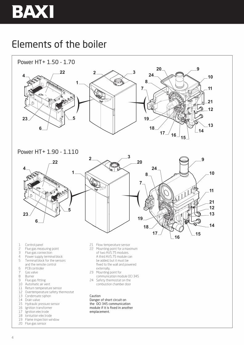
Elements of the boiler
Power HT+ 1.50 - 1.70
1
2
78
2420
4322
9
10
11
2112
13146
1516
1923
1817
5
1
2 32022
5
6
4
9
10
11
21
14
1516
1213
7
824
1923
1817
Power HT+ 1.90 - 1.110
1 Control panel2 Flue gas measuring point3 Flue gas connection4 Power supply terminal block5 Terminal block for the sensors and the remote control6 PCB controller7 Gas valve8 Burner9 Flue gas fitting10 Automatic air vent11 Return temperature sensor12 Overtemperature safety thermostat13 Condensate siphon14 Drain valve15 Hydraulic pressure sensor16 Ignition transformer17 Ignition electrode18 Ionisation electrode19 Flame inspection window20 Flue gas sensor
21 Flow temperature sensor22 Mounting point for a maximum of two AVS 75 modules. A third AVS 75 module can be added, but it must be fixed to the wall and powered externally.23 Mounting point for communication module OCI 34524 Safety thermostat on the combustion chamber door
CautionDanger of short circuit on the OCI 345 communication module if it is fixed in another emplacement.

5
Power HT+
Power HT+ 1.130 - 1.150
Dispositivo DescrizioneDispositivo di protezione antigelo Quando la temperatura di mandata è inferiore a 5 °C, il bruciatore viene avviato e resta
in funzione fino a che la temperatura di mandata non raggiunge i 15 °C. Il dispositivo funziona nelle seguenti condizioni:
La caldaia è accesaIl rubinetto del gas è apertoLa pressione dell'impianto è superiore a 0,5 bar (0,05 MPa)
Anti bloccaggio della pompa Se non vi sono richieste di riscaldamento o acqua calda sanitaria per 24 ore consecutive, le pompe vengono avviate automaticamente e restano in funzione per 10 secondi.Le pompe collegate direttamente alle morsettiere dell'apparecchio vengono avviate ogni venerdì alle 10.00 e restano in funzione per 30 secondi.
Avvio anticipato dei circolatori Solo in modalità riscaldamento l'apparecchio può avviare i circolatori prima dell'accensione del bruciatore. La durata e l'attivazione dell'avvio anticipato dipendono dai requisiti di installazione e dalle temperature di funzionamento. La durata dell'avvio anticipato dei circolatori varia pertanto da alcuni secondi a diversi minuti.
Pressostato fumi Il pressostato dei fumi interrompe l'aspirazione del gas al bruciatore in caso di ostruzione del tubo di scarico con prodotti della combustione o il tubo di ingresso dell'aria di combustione.
4.3 Componenti principali
4.3.1 POWER HT+ 1.130 e POWER HT+ 1.150
19
20
21
18 17
1415
8
56
4
1312
10
22
23
2425
1
79
11
16
3
2
26
4 Descrizione del prodotto
7702635 - v02 - 11082018 POWER HT + 23
1 Pannello di controllo2 Collegamento fumi3 Presa analisi gas di scarico4 PCB controller5 Punto di installazione per un massimo di due moduli
AVS 75. È possibile utilizzare un terzo modulo AVS 75, ma la caldaia deve essere fissata alla parete e alimentata esternamente.
6 Morsettiera di alimentazione7 Morsettiera per sonde e telecomando8 Posizione di montaggio del modulo di
comunicazione OCI 345
AttenzionePericolo di cortocircuito sul modulo di comunicazione OCI 345 se viene collocata in un'altra posizione.
9 Posizione di montaggio del modulo di conversione AGU 2.551
10 Valvola gas11 Sonda di ionizzazione12 Bruciatore13 Elettrodo di accensione14 Finestra per ispezione fiamma15 Termostato di sicurezza sulla porta del focolare16 Trasformatore di accensione17 Sonda di pressione idraulica18 Sonda temperatura di ritorno19 Sonda fumi20 Raccordi fumi21 Pressostato fumi22 Sfiatatoio automatico23 Termostato di sicurezza24 Sonda temperatura di mandata25 Valvola di scarico26 Sifone condensati
4.3.2 POWER HT+ 1.200 e POWER HT+ 1.250
12
15
16
13
11
10
20
21
24
19
17
187
3
1
2
23
22
14
25
26
89
54
6
1 Pannello di controllo2 Collegamento fumi3 Presa analisi gas di scarico4 PCB controller5 Punto di installazione per un massimo di due moduli
AVS 75. È possibile utilizzare un terzo modulo AVS 75, ma la caldaia deve essere fissata alla parete e alimentata esternamente.
6 Morsettiera di alimentazione7 Morsettiera per sonde e telecomando8 Posizione di montaggio del modulo di
comunicazione OCI 345
AttenzionePericolo di cortocircuito sul modulo di comunicazione OCI 345 se viene collocata in un'altra posizione.
9 Posizione di montaggio del modulo di conversione AGU 2.551
10 Valvola gas11 Sonda di ionizzazione12 Bruciatore13 Elettrodo di accensione14 Finestra per ispezione fiamma15 Termostato di sicurezza sulla porta del focolare16 Trasformatore di accensione17 Sonda di pressione idraulica18 Pressostato fumi19 Sfiatatoio automatico20 Sonda fumi21 Raccordi fumi22 Sonda temperatura di ritorno23 Sonda temperatura di mandata24 Valvola di scarico
4 Descrizione del prodotto
24 POWER HT + 7702635 - v02 - 11082018
Power HT+ 1.200 - 1.250
1 Control panel2 Flue gas connection3 Flue gas measuring point4 PCB controller5 Mounting point for a maximum of two AVS 75 modules. A third AVS 75 module can be added, but it must be fixed to the wall and powered externally.6 Power supply terminal block7 Terminal block for the sensors and the remote control8 Mounting point for communication module OCI 3459 Mounting point forAGU 2.55110 Gas valve
11 Ionisation electrode12 Burner13 Ignition electrode14 Flame inspection window15 Safety thermostat on the combustion chamber door 16 Ignition transformer17 Hydraulic pressure sensor 18 Return temperature sensor (130-150 kW) / Flue pressure sensor (200-250 kW)19 Flue gas sensor (130-150 kW) / Automatic air vent (200-250 kW)20 Flue gas fitting (130-150 kW) / Flue gas sensor (200-250 kW) 21 Flue pressure sensor (130-150 kW) / Flue gas fitting (200-250 kW)
22 Automatic air vent (130-150 kW) / Return temperature sensor (200-250 kW)23 Overtemperature safety thermostat (130-150 kW) / Flow temperature sensor (200-250 kW)24 Flow temperature sensor (130-150 kW)/ Drain valve (200-250 kW)25 Drain valve (130-150 kW)26 Condensate siphon CautionDanger of short circuit on the OCI 345 communication module if it is fixed in another emplacement.

6
The air-gas premixing unit, the burner and the primary exchanger are the components that ensure high performances from these condensing heat generators. The premixing unit is a new conception which, thanks to a new design and the double clapet technique, ensures that the burner constantly has an optimal air/gas ratio independently from the number of fan revs, keeping consumption to a minimum and always guaranteeing correct combustion and consequently a reduction in polluting emissions. On the same subject of energy saving and highest performances, this new component permits achievement of a modulation ratio of 1:9 (1:5 in 130-250 kW range), giving the generator such great flexibility as to be adaptable to great variations in thermal load, as happens increasingly in new generation multifamily homes.In the range from 50 to 250 kW the stainless steel burner, through the internal diffuser and special micro-perforation on the cylindrical surface, achieves uniform distribution of the air/gas mixture independently of its length. In 110 kW boiler the burner is in metal fibre. This produces a spread of very short flame for optimal heat radiation while minimising the formation of nitrogen oxides.In the range from 50 to 70 kW the primary exchanger, entirely in stainless steel, comprises one single burner/fumes chamber, which keeps the size of the generator down for high power and actually more versatile installations even in relatively restricted spaces. The two highest powered generators (90 and 250 kW) employ the dual chamber exchanger in stainless steel. The two cylindrical fumes chambers set vertically (burner chamber and condensation chamber) contain the stainless steel coils that carry the primary circuit water. In the upper chamber the hot exhaust gases transfer heat to the system return water in the coils, bringing about condensation of the fumes themselves and thus transferring the latent heat to the water, preheating it prior to its entry into the burner chamber.
Burner / Exchanger unit
ErP Pump-main features:• Remotely speed–controlled, high-efficiency pump fitted
with electronically commutated motor (ECM) with permanent-magnet rotor and frequency converter
• Validated components, second generation of the first boiler-integrated variable-speed ECM circulator pumps
• Fits into existing boiler ranges, no expanded space requirements, possible use of existing pump housings, electrical compatibility with existing PWM controllers and no ambient-temperature constraints (EN 60335)
• Energy-optimized due to improved hydraulic efficiency. Use up to 80% less electrical power than conventional constant-speed pumps
30 35 40
Flue
tem
pera
ture
[ °C
]
Return temperature °C
45 50 55 6030354045505560657075
100% load
30% load
FLUE TEMPERATURE/RETURN TEMPERATURE
FLUE TEMPERATURE/RETURN TEMPERATURE
EFFICIENCY/RETURN TEMPERATURE
30 35 40
Effi
cien
cy %
Return temperature °C
EFFICIENCY/RETURN TEMPERATURE
30% load
100% load
45 50 55 60979899
100101102103104105106107108

7
Power HT+
Single installationDimensionsPower HT+ 1.50 - 1.70
Hydraulic exchanger losses and pump head curves
Power HT+ 1.50 Power HT+ 1.70
H (m
)
0 0,5 1 1,5 2 2,5 3 3,5 4 4,5 5 5,5 6 6,5 7 7,5Q (m3/h)
12
2
0
4
6
8
10
H (m
)
12
2
0
4
6
8
10
H (m
)
12
2
0
4
6
8
10
H (m
)
12
2
0
4
6
8
10
0 0,5 1 1,5 2 2,5 3 3,5 4 4,5 5 5,5 6 6,5 7 7,5Q (m3/h)
0 0,5 1 1,5 2 2,5 3 3,5 4 4,5 5 5,5 6 6,5 7 7,5Q (m3/h)
0 0,5 1 1,5 2 2,5 3 3,5 4 4,5 5 5,5 6 6,5 7 7,5Q (m3/h)
H (m
)
0 0,5 1 1,5 2 2,5 3 3,5 4 4,5 5 5,5 6 6,5 7 7,5Q (m3/h)
12
2
0
4
6
8
10
H (m
)
12
2
0
4
6
8
10
H (m
)
12
2
0
4
6
8
10
H (m
)
12
2
0
4
6
8
10
0 0,5 1 1,5 2 2,5 3 3,5 4 4,5 5 5,5 6 6,5 7 7,5Q (m3/h)
0 0,5 1 1,5 2 2,5 3 3,5 4 4,5 5 5,5 6 6,5 7 7,5Q (m3/h)
0 0,5 1 1,5 2 2,5 3 3,5 4 4,5 5 5,5 6 6,5 7 7,5Q (m3/h)
Hydraulic exchanger losses
Pump head (in the hydraulic accessory)
Bolier + hydraulics
Dual flue systemHydraulic connections
1 Heating system return (G1”)2 Heating system flow (G1”)3 Gas inlet (G3/4”)4 Condensing trap (DN18)(1) Adjustable feet
9 9
353 247600
848
56
618,5
300
683
468,5
220
160
519
569
240 681
8
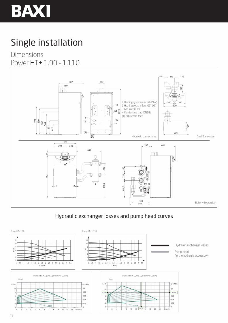
Single installationDimensionsPower HT+ 1.90 - 1.110
Hydraulic exchanger losses and pump head curves
Power HT+ 1.90 Power HT+ 1.110
H (m
)
0 0,5 1 1,5 2 2,5 3 3,5 4 4,5 5 5,5 6 6,5 7 7,5Q (m3/h)
12
2
0
4
6
8
10
H (m
)
12
2
0
4
6
8
10
H (m
)
12
2
0
4
6
8
10
H (m
)
12
2
0
4
6
8
10
0 0,5 1 1,5 2 2,5 3 3,5 4 4,5 5 5,5 6 6,5 7 7,5Q (m3/h)
0 0,5 1 1,5 2 2,5 3 3,5 4 4,5 5 5,5 6 6,5 7 7,5Q (m3/h)
0 0,5 1 1,5 2 2,5 3 3,5 4 4,5 5 5,5 6 6,5 7 7,5Q (m3/h)
H (m
)
0 0,5 1 1,5 2 2,5 3 3,5 4 4,5 5 5,5 6 6,5 7 7,5Q (m3/h)
12
2
0
4
6
8
10
H (m
)
12
2
0
4
6
8
10
H (m
)
12
2
0
4
6
8
10
H (m
)
12
2
0
4
6
8
10
0 0,5 1 1,5 2 2,5 3 3,5 4 4,5 5 5,5 6 6,5 7 7,5Q (m3/h)
0 0,5 1 1,5 2 2,5 3 3,5 4 4,5 5 5,5 6 6,5 7 7,5Q (m3/h)
0 0,5 1 1,5 2 2,5 3 3,5 4 4,5 5 5,5 6 6,5 7 7,5Q (m3/h)
Hydraulic exchanger losses
Pump head (in the hydraulic accessory)
Bolier + hydraulics
Dual flue systemHydraulic connections
618,5
300
300 300
600
1127
94
9 9
683
468,5
220
160
240 681
519569
1 Heating system return (G1”1/2)2 Heating system flow (G1” 1/2)3 Gas inlet (G1”)4 Condensing trap (DN18)(1) Adjustable feet
POWER HT+ 1.200-1.250 PUMP CURVEPOWER HT+ 1.130-1.150 PUMP CURVE
Head Head
9
Power HT+
Hydraulic exchanger losses
Pump head (in the hydraulic accessory)
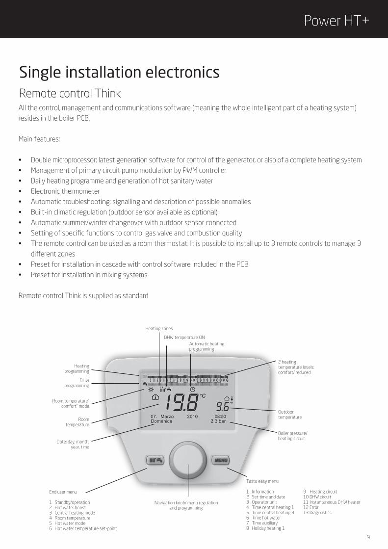
Single installation electronicsRemote control ThinkAll the control, management and communications software (meaning the whole intelligent part of a heating system) resides in the boiler PCB.
Main features:
• Double microprocessor: latest generation software for control of the generator, or also of a complete heating system• Management of primary circuit pump modulation by PWM controller• Daily heating programme and generation of hot sanitary water• Electronic thermometer• Automatic troubleshooting: signalling and description of possible anomalies• Built-in climatic regulation (outdoor sensor available as optional)• Automatic summer/winter changeover with outdoor sensor connected• Setting of specific functions to control gas valve and combustion quality• The remote control can be used as a room thermostat. It is possible to install up to 3 remote controls to manage 3 different zones• Preset for installation in cascade with control software included in the PCB• Preset for installation in mixing systems
Remote control Think is supplied as standard
DHWprogramming
Room temperature“ comfort” mode
Roomtemperature
Date: day, month,year, time
Outdoortemperature
Boiler pressure/heating circuit
Navigation knob/ menu regulation and programming
End user menu
1 Standby/operation2 Hot water boost3 Central heating mode4 Room temperature5 Hot water mode6 Hot water temperature set-point
Heatingprogramming
Heating zones
DHW temperature ONAutomatic heating programming
2 heatingtemperature levels: comfort/ reduced
Tasto easy menu 1 Information2 Set time and date3 Operator unit4 Time central heating 15 Time central heating 36 Time hot water7 Time auxiliary8 Holiday heating 1
9 Heating circuit10 DHW circuit11 Instantaneous DHW heater12 Error 13 Diagnostics

10
Electronic accessories for installations
Remote control THINK
Bus module (OCI 345)
Code 7102442 (wired)Code 7102443 (wireless)
Code 7104408
The room unit is an accessory for controlling the temperature of the space to be heated. It is not only a modulating climate controller, capable of adjusting the delivery temperature from the boiler to obtain the desired room temperature with greatest efficiency: it also functions as a programmer, setting heating system parameters. including boilers in cascade and various low temperature zones.
The THINK interface for boilers in cascade (BUS MODULE) is an electronic device that allows the bus communication (two wires) between boilers in a cascade system or between a single boiler (or the cascade boiler system) and a mixed zone controller THINK.
11
Power HT+
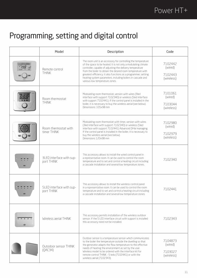
Programming, setting and digital control
Model Description Code
Remote controlTHINK
The room unit is an accessory for controlling the temperature of the space to be heated. It is not only a modulating climate controller, capable of adjusting the delivery temperature from the boiler to obtain the desired room temperature with greatest efficiency: it also functions as a programmer, setting heating system parameters. including boilers in cascade and various low temperature zones.
7102442(wired)
7102443(wireless)
Room thermostatTHINK
Modulating room thermostat, version with wires (3led interface with support 7102340) or wireless (5led interface with support 7102441). If the control panel is installed in the boiler, it is necessary to buy the wireless aerial (see below). Dimensions: 105x98 mm
7101061(wired)
7103044(wireless)
Room thermostat with timer THINK
Modulating room thermostat with timer, version with wires (3led interface with support 7102340) or wireless (5led interface with support 7102441) Advanced DHW managing. If the control panel is installed in the boiler, it is necessary to buy the wireless aerial (see below). Dimensions 120x98 mm
7102980(wired)
7102979(wireless)
3LED interface with sup-port THINK
This accessory allows to install the wired control panel in a representative room. It can be used to control the room temperature and to set and control a heating circuit including a cascade installation and several low temperature zones.
7102340
5LED interface with sup-port THINK
This accessory allows to install the wireless control panel in a representative room. It can be used to control the room temperature and to set and control a heating circuit including a cascade installation and several low temperature zones.
7102441
Wireless aerial THINKThis accessory permits installation of the wireless outdoor sensor. If the 5 LED interface circuit with support is installed this accessory need not be installed.
7102343
Outodoor sensor THINK(QAC34)
Outdoor sensor is a temperature sensor which communicates to the boiler the temperature outside the dwelling so that the generator adapts the flow temperature to the effective needs of heating the environment as set by the user. Wireless model to be ordered with the interface kit for remote control THINK - 5 leds (7102441) or with the wireless aerial (7102343).
7104873(wired)
7103027(wireless)
12
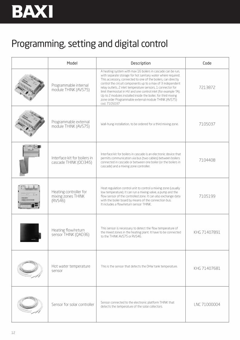
Programming, setting and digital control
Model Description Code
Programmable internal module THINK (AVS75)
A heating system with max 16 boilers in cascade can be run, with separate storage for hot sanitary water where required. This accessory, connected to one of the boilers, can directly control the circuit components up to a max of 3 independent relay outlets, 2 inlet temperature sensors, 1 connector for limit thermostat in HV and one control inlet (for example TA). Up to 2 modules installed inside the boiler, for third mixing zone order Programmable external module THINK (AVS75) cod. 7105037
7213872
Programmable external module THINK (AVS75)
Wall-hung installation, to be ordered for a third mixing zone. 7105037
Interface kit for boilers in cascade THINK (OCI345)
Interface kit for boilers in cascade is an electronic device that permits communication via bus (two cables) between boilers connected in cascade or between one boiler (or the boilers in cascade) and a mixing zone controller.
7104408
Heating controller for mixing zones THINK(RVS46)
Heat regulation control unit to control a mixing zone (usually low temperature). It can run a mixing valve, a pump and the flow sensor of the controlled zone. It can also exchange data with the boiler board by means of the connection bus.It includes a flow/return sensor THINK.
7105199
Heating flow/return sensor THINK (QAD36)
This sensor is necessary to detect the flow temperature of the mixed zones in the heating plant. It have to be connected to the THINK AVS75 or RVS46.
KHG 71407891
Hot water temperature sensor
This is the sensor that detects the DHW tank temperature. KHG 71407681
Sensor for solar controller Sensor connected to the electronic platform THINK that detects the temperature of the solar collectors. LNC 71000004

13
Power HT+
AS STANDARD
AVS75
AS STANDARD
AVS75REMOTE CONTROL
MIX ZONE TEMP.
SENSOR
MIX ZONE TEMP.SENSOR
P2 P2 P2
P3VM
P3VM
QAD 21
HOT WATER TEMPERATURE SENSOR
R2
Th
R1
P2
P2
P3VM
P3VM
P3VM
P3VM
P3VM
nnn X30
BX21MBX22MH2M
X50
LN
LNQX21NL QX22QX23
TSC
LFX23EX21
2
1 1 2
3
1 2
ON
nnn X30
BX21MBX22MH2M
X50
LN
LNQX21NL QX22QX23
TSC
LFX23EX21
2
1 1 2
3
1 2
ON +
n°2 AVS75 n°2 MIX ZONE TEMP. SENSOR
nnn X30
BX21MBX22MH2M
X50
LN
LNQX21NL QX22QX23
TSC
LFX23EX21
2
1 1 2
3
1 2
ON +
n°3 AVS75 n°3 MIX ZONE TEMP. SENSOR
nnn X30
BX21MBX22MH2M
X50
LN
LNQX21NL QX22QX23
TSC
LFX23EX21
2
1 1 2
3
1 2
ON +
Configurations

14
P2
P3VM
P3VM
P3VM
P3VM
+ + + +n°3 AVS75 MIX ZONE CONTROLn°1 BUS
MODULEREMOTE CONTROL n°4 MIX ZONE
TEMP. SENSOR
nnn X30
BX21MBX22MH2M
X50
LN
LNQX21NL QX22QX23
TSC
LFX23EX21
2
1 1 2
3
1 2
ON
EX21 FX23 L
C S T
QX23 QX22L N QX21 N L
N L
X50
H2 M BX22 M BX21
X30n n n
M
ON
1 2
1 21
2 3
+ + +SENSOR FOR
SOLAR CONTROLLERn°2 AVS75 HOT WATER
TEMPERATURE SENSORMIX ZONE
TEMP. SENSOR
nnn X30
BX21MBX22MH2M
X50
LN
LNQX21NL QX22QX23
TSC
LFX23EX21
2
1 1 2
3
1 2
ON
+ +SOLAR TEMP. SENSOR AVS75 TANK TEMP. SENSOR
nnn X30
BX21MBX22MH2M
X50
LN
LNQX21NL QX22QX23
TSC
LFX23EX21
2
1 1 2
3
1 2
ON
P2
P2
P3VM

15
Power HT+
Expansion vessel kit
Boiler-manifolds connection kit
Manifold insulation kit for one boiler
* The hydraulic separator is handled as a separate accessory
Flanges and gaskets kit
Hydraulic connection kitto the separator
Single installationPower HT+ 1.50 - 1.70
Expansion vessel Power HT+
Flow-return-gas manifolds kit for single installation with flanges and gaskets
Boiler-manifolds connection kit with high efficiency pump Power HT+ 50-70 kW
Hydraulic connection to the separator kit 2" (8,5 m3/h)
Hydraulic separator 2" (8,5 m3/h)

16
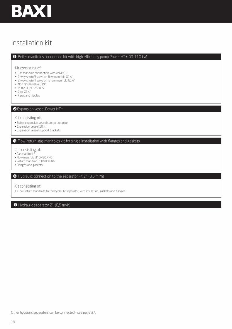
Installation kit
Boiler-manifolds connection kit with high efficiency pump Power HT+ 50-70 kW
Kit consisting of:• Gas manifold connection with valve G1”• 2 way shutoff valve on flow manifold G1¼” • 2 way shutoff valve on return manifold G1¼” • Non return valve G1¼”• Pump UPML 25/105• Cap G1¼”• Pipes and nipples
Expansion vessel Power HT+
Kit consisting of:• Boiler-expansion vessel connection pipe• Expansion vessel 10 lt• Expansion vessel support brackets
Flow-return-gas manifolds kit for single installation with flanges and gaskets
Kit consisting of:• Gas manifold 2”• Flow manifold 3” DN80 PN6• Return manifold 3” DN80 PN6• Flanges and gaskets • Insulation kit for single boiler flow/return manifolds
Hydraulic connection to the separator kit 2" (8,5 m3/h)
Kit consisting of:• Flow/return manifolds to the hydraulic separator, with insulation, gaskets and flanges
Other hydraulic separators can be connected - see page 37.
Hydraulic separator 2" (8,5 m3/h)

17
Power HT+
Single installationPower HT+ 1.90 - 1.110
Hydraulic connection to the separator kit 2" (8,5 m3/h)
Expansion vessel Power HT+
Boiler-manifolds connection kit with high efficiency pump Power HT+ 90 -110 kW
Flow-return-gas manifolds kit for single installation with flanges and gaskets
Expansion vessel kit
Boiler-manifolds connection kit
Manifold insulation kit for one boiler
* The hydraulic separator is handled as a separate accessory
Flanges and gaskets kit
Hydraulic connection kitto the separator
Hydraulic separator 2" (8,5 m3/h)
18
Installation kit
Boiler-manifolds connection kit with high efficiency pump Power HT+ 90-110 kW
Kit consisting of:• Gas manifold connection with valve G1”• 2 way shutoff valve on flow manifold G1¼” • 2 way shutoff valve on return manifold G1¼” • Non return valve G1¼”• Pump UPML 25/105• Cap G1¼”• Pipes and nipples
Expansion vessel Power HT+
Kit consisting of:• Boiler-expansion vessel connection pipe• Expansion vessel 10 lt• Expansion vessel support brackets
Flow-return-gas manifolds kit for single installation with flanges and gaskets
Kit consisting of:• Gas manifold 2”• Flow manifold 3” DN80 PN6• Return manifold 3” DN80 PN6• Flanges and gaskets
Hydraulic connection to the separator kit 2" (8,5 m3/h)
Kit consisting of:• Flow/return manifolds to the hydraulic separator, with insulation, gaskets and flanges
Hydraulic separator 2" (8,5 m3/h)
Other hydraulic separators can be connected - see page 37.

19
Power HT+
Single installationPower HT+ 1.130 - 1.150 with hydraulic separator
Power HT+ 1.200 - 1.250 with hydraulic separator
Power HT+ 1.130 - 1.150 with plate exchanger
Power HT+ 1.200 - 1.250 with plate exchanger

20
Hydraulic separator - for single installation Power HT+ 50/70 kWDimensions 848 x 600 x 250 mmCode 7607401
Hydraulic separator - for single installation Power HT+ 90/110 kWDimensions 1147 x 600 x 250 mmCode 7606357
This new accessory is a hidden separator that can be installed behind the boiler: it has been designed to facilitate the single installation of Power HT+ boilers, to save space and provide an easy way for installation. The accessory can be easily fixed in the rear side of the boiler.
The expansion vessel must be installed on site, outside the accessory to mount the hydraulic separator behind the boiler.
Hydraulic separator back connection - single installation

21
Power HT+
Picture Description Code
PP dual flue system Ø 80 it includes:flue reduction, intake connection
KHG 71408901
PP pipe extension Ø 80 L=1000 mm KHG 71405941
PP pipe extension Ø 80 L=500 mm KHG 71405991
PP pipe extension Ø 80 L=250 mm 7107183
PP 90° bend Ø 80 KHG 71405921
PP 45° bend Ø 80 KHG 71405931
Pipe Ø 80 centring kit (pack of 5) KHG 71403741
Clamp centring kit Ø 80 KHG 71410611
Pipe Ø 80 supporting bracket (pack of 5) KHG 71403731
Internal sealing collar Ø 80 KHG 71401851
External sealing collar Ø 80 KHG 71401841
Coaxial vertical chimney terminal 80/125 KHG 71409351
Dual flue pipes adapter for coaxial chimney KHG 71409381
Flue terminal Ø 80 LSD 79000015
Dual flue terminal Ø 80 KHG 71401041
Flat roof tile Ø 125 to be used with a vertical chimney terminal
KHG 71409361
Pitched roof tile Ø 125 to be used with a vertical chimney terminal; it is adjustable from 15° to 45°
KHG 71409371
Power HT+ 1.50-1.70Dual flue system accessories Ø 80

22
Picture Description Code
PP flexible pipe Ø 80 L= 1,5 m KHG 71410571
PP flexible pipe Ø 80 L= 20 m KHG 71410581
PP tee joint Ø 80 with supporting bracket and condensate drainings
KHG 71410591
PP 90° bend Ø 80 with supporting bracket KHG 71410601
Flexible centring kit Ø 80 (pack of 3) KHG 71410621
Triple lips gaskets kit Ø 80 (pack of 5) KHG 71411121
Power HT+ 1.50-1.70Flexible ducting system accessories

23
Power HT+
Picture Description Code
PP dual fllue kit Ø 110/110 7106314
PP pipe extension Ø 110 L=1000 mm KUG 71413321
PP pipe extension Ø 110 L=500 mm KUG 71413311
PP pipe extension Ø 110 L=250mm 7107185
PP 90° bend Ø 110 KUG 71413301
PP 45° bend Ø 110 KUG 71413291
PP vertical chimney terminal Ø 110 KUG 71413281
PP horizontal chimney terminal Ø 110 KUG 71413271
Flat roof tile to be used with a vertical chimney terminal Ø 110/160
KHG 71410481
Pitched roof tile to be used with a vertical chimney terminal 110/160; it is adjustable from 15° to 45°
KHG 71410491
Power HT+ 1.90-1.110Dual flue system accessories Ø 110
24
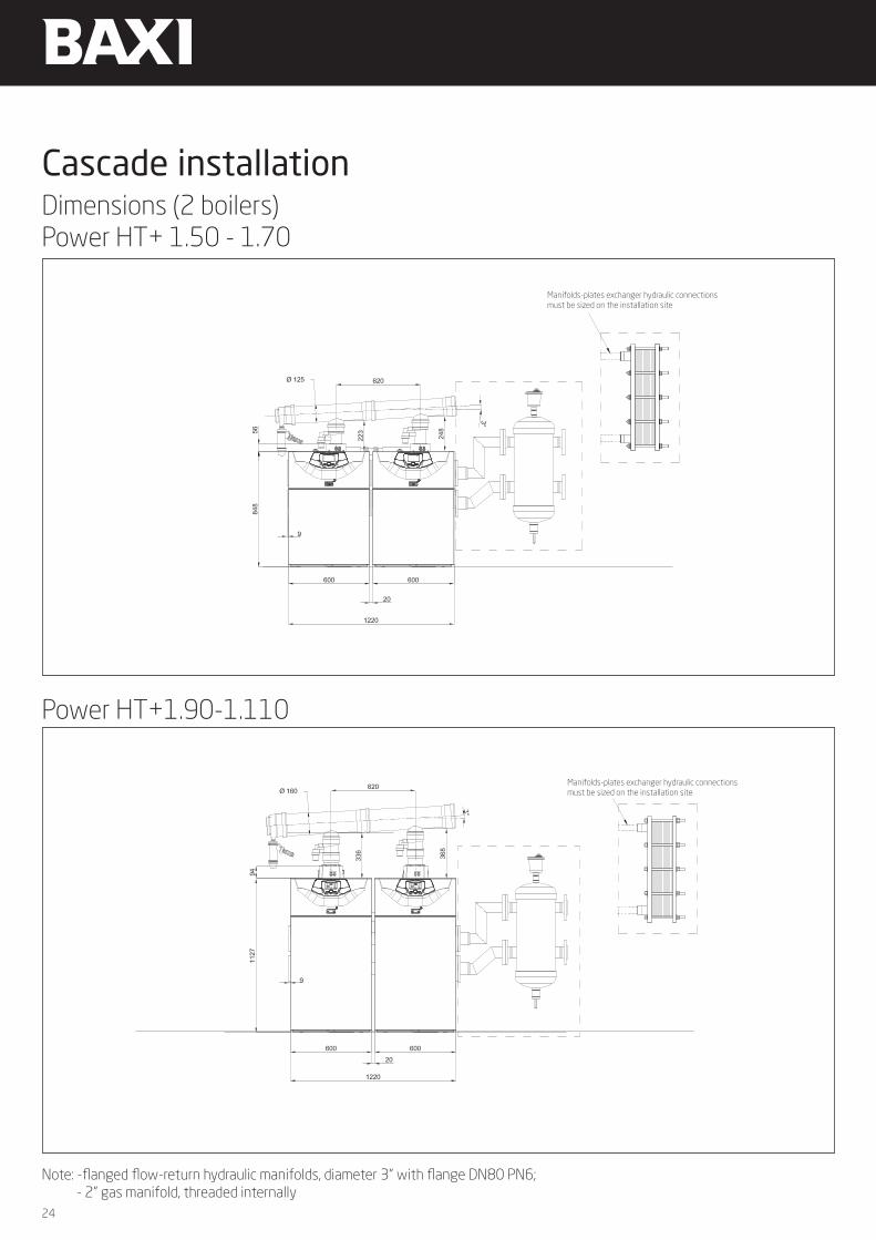
Note: -flanged flow-return hydraulic manifolds, diameter 3” with flange DN80 PN6; - 2” gas manifold, threaded internally
Power HT+1.90-1.110
Manifolds-plates exchanger hydraulic connections must be sized on the installation site
Manifolds-plates exchanger hydraulic connections must be sized on the installation site
Dimensions (2 boilers)Power HT+ 1.50 - 1.70
Cascade installation

25
Power HT+
726
2126
1476
636 600 140 600
1190
Ø 11
4.3
Ø 11
4.3
718
1058
110401
1502
636 600 140 600
2128
1973
Ø 11
4.3
Ø 11
4.3
744
1084
726
110452
Dimensions (2 boilers)Power HT+ 1.130 - 1.150
Power HT+1.200-1.250

26
List of accessories, 2 boilers in cascadeCode 100 kW 140 kW 180 kW 220 kW 260 kW 300 kW 400 kW 500 kW
BO
ILER
S
Power HT+ 1.50 7612418 2
Power HT+ 1.70 7612419 2
Power HT+ 1.90 7612420 2
Power HT+ 1.110 7612421 2
Power HT+ 1.130 7689649 2
Power HT+ 1.150 7689651 2
Power HT+ 1.200 7689652 2
Power HT+ 1.250 7689653 2
THER
MOR
EGUL
ATIO
N
Outdoor sensor THINK (QAC 34) 7104873 1 1 1 1
Interface kit for boilers in cascade THINK(BUS MODULE OCI 345) 7104408 2 2 2 2
Hot water temperature sensor KHG 71407681 1 1 1 1
Programmable internal module THINK (AVS75) - max 2 mixing zones 7213872 max 2 max 2 max 2 max 2
Programmable external module THINK (AVS75) - third mixing zone 7105037 max 1 max 1 max 1 max 1
HYD
RAU
LIC
ACCE
SSO
RIES
Flow-return-gas manifolds, insulation, flanges and gaskets kit for 2 boilers 50-110 kW* 7662216 1 1 1 1
Expansion vessel kit 7213919 2 2 2 2
Boiler-manifolds connection kit 50-70 kW with high efficiency pump 7213843 2 2
Boiler-manifolds connection kit 90-110 kW with high efficiency pump 7213806 2 2
Hydraulic connection kitto the separator 8,5 m3/h G2" 7218613 1 1
Hydraulic separator 8,5 m3/h G2" LSD 79000031 1 1
Hydraulic connection kit to the separator18 m3/h DN65 7218614 1 1
Hydraulic separator 18 m3/h DN65 LSD 79000032 1 1
Collector hydraulic+gas kit 1boiler 7694125 2 2
Kit cascade piping 150kW+gas 7673764 2 2
Collector hydraulic+gas kit 1boiler 7694125 2 2
Kit cascade piping 250kW+gas 7694143 2 2
Kit hydraulic separator 30m3/h 7694133 1 1 1 1
FLU
E A
CCES
SORI
ES
Shutter kit Ø110/80 with condensing trap 7106820 2 2
Shutter kit Ø110/110 with condensing trap 7106821 2 2
Flue pipe kit for 2 boilers Ø125/110 7107168 1 1
Flue pipe kit for 2 boilers Ø160/110 7107152 1 1
PP Pipe extension Ø110 L=250mm 7107185 2 2
* This accessory is available also without gas line (cod. 7662220)
27
Power HT+
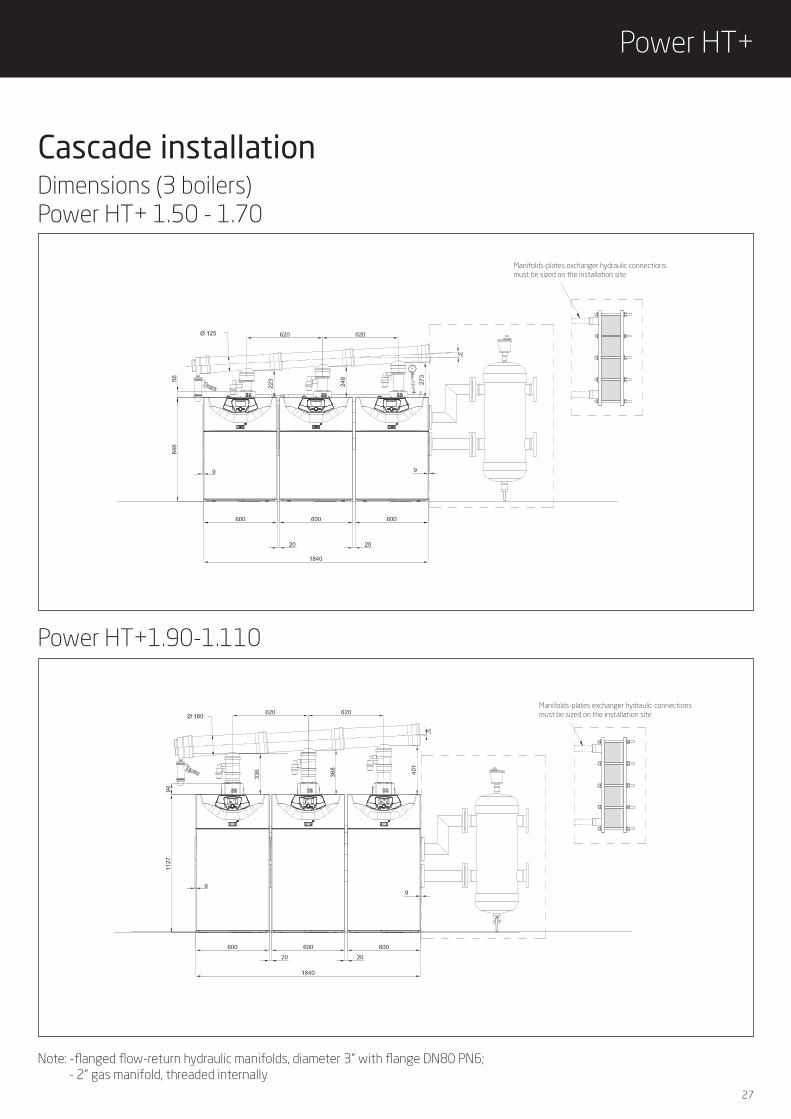
Cascade installation
Power HT+1.90-1.110
Manifolds-plates exchanger hydraulic connections must be sized on the installation site
Dimensions (3 boilers)Power HT+ 1.50 - 1.70
Note: -flanged flow-return hydraulic manifolds, diameter 3” with flange DN80 PN6; - 2” gas manifold, threaded internally
Manifolds-plates exchanger hydraulic connections must be sized on the installation site

28
List of accessories, 3 boilers in cascadeCode 150 kW 210 kW 270 kW 330 kW 390 kW 450 kW 600 kW 750 kW
BO
ILER
S
Power HT+ 1.50 7612418 3
Power HT+ 1.70 7612419 3
Power HT+ 1.90 7612420 3
Power HT+ 1.110 7612421 3
Power HT+ 1.130 7689649 3
Power HT+ 1.150 7689651 3
Power HT+ 1.200 7689652 3
Power HT+ 1.250 7689653 3
THER
MOR
EGUL
ATIO
N
Outdoor sensor THINK (QAC 34) 7104873 1 1 1 1
Interface kit for boilers in cascade THINK(BUS MODULE OCI 345) 7104408 3 3 3 3
Hot water temperature sensor KHG 71407681 1 1 1 1
Programmable internal module THINK (AVS75) - max 2 mixing zones 7213872 max 2 max 2 max 2 max 2
Programmable external module THINK (AVS75) - third mixing zone 7105037 max 1 max 1 max 1 max 1
HYD
RAU
LIC
ACCE
SSO
RIES
Flow-return-gas manifolds, insulation, flanges and gaskets kit for 2 boilers 50-110 kW* 7662216 1 1 1 1
Flow-return-gas manifolds, insulation, flanges and gaskets kit for third boiler 50-110 kW** 7662214 1 1 1 1
Expansion vessel kit 7213919 2 2 2 2
Boiler-manifolds connection kit 50-70 kW with high efficiency pump 7213843 3 3
Boiler-manifolds connection kit 90-110 kW with high efficiency pump 7213806 3 3
Hydraulic connection kit to the separator18 m3/h DN65 7218614 1 1
Hydraulic separator 18 m3/h DN65 LSD 79000032 1 1
Hydraulic connection kit to the separator28 m3/h DN80 7218615 1 1
Hydraulic separator 28 m3/h DN80 LSD 79000033 1 1
Collector hydraulic+gas kit 1boiler 7694125 3 3
Kit cascade piping 150kW+gas 7673764 3 3
Collector hydraulic+gas kit 1boiler 7694125 3 3
Kit cascade piping 250kW+gas 7694143 3 3
Kit hydraulic separator 30m3/h 7694133 1 1 1 1
FLU
E A
CCES
SORI
ES
Shutter kit Ø110/80 with condensing trap 7106820 3 3
Shutter kit Ø110/110 with condensing trap 7106821 3 3
Flue pipe kit for 2 boilers Ø125/110 7107168 1
Flue pipe kit for 2 boilers Ø160/110 7107152 1 1
Flue pipe kit for the third boiler Ø125/110 7107177 1
Flue pipe kit for the third boiler Ø160/110 7107163 1 1
PP Pipe extension Ø110 L=250mm 7107185 1 3 3 3
Flue pipe kit for 2 boilers Ø200 7107156 1
Flue pipe kit for the third boiler Ø200 7107164 1
* This accessory is available also without gas line (cod. 7662220)** This accessory is available also without gas line (cod. 7662218)
29
Power HT+
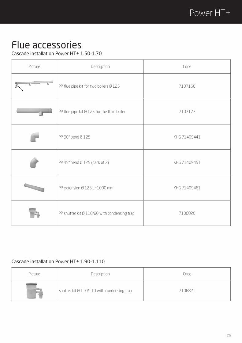
Picture Description Code
Shutter kit Ø 110/110 with condensing trap 7106821
Picture Description Code
PP flue pipe kit for two boilers Ø 125 7107168
PP flue pipe kit Ø 125 for the third boiler 7107177
PP 90° bend Ø 125 KHG 71409441
PP 45° bend Ø 125 (pack of 2) KHG 71409451
PP extension Ø 125 L=1000 mm KHG 71409461
PP shutter kit Ø 110/80 with condensing trap 7106820
Cascade installation Power HT+ 1.50-1.70Flue accessories
Cascade installation Power HT+ 1.90-1.110

30
Picture Description Code
PP flue pipe kit Ø 160 for two boilers 7107152
PP flue pipe kit Ø 200 for two boilers 7107156
PP flue pipe kit Ø 160 for the third boiler 7107163
PP flue pipe kit Ø 200 for the third boiler 7107164
PP 90° bend Ø 160 KHW 71409781
PP 90° bend Ø 200 KHW 71409821
PP extension Ø 160 L=1000 mm KHW 71409771
PP extension Ø 110 L=250 mm 7107185
PP extension Ø 200 L=1000 mm KHW 71409811
Cascade installation Power HT+ 1.90-1.110Flue accessories

31
Power HT+
Flue systems - single installationThe boiler can be easily installed thanks to the flue accessories provided by BAXI, which offer a great flexibility of use.The product is certified for the following flue types:B23 – C13 – C33 – C43 – C53 – C63 – C83
C63 The maximum pressure drop in the pipes ΔP not provided by BAXI must not exceed the values given in the table below.
In case of installation of flue pipe not provided by BAXI, the pipes must be certified for this type of use and for a temperature higher than 100°C. The terminal part of the flue gas pipe must be certified as complying with the EN 1856-1 standard.
Flue type C63
Fan pressure drop (*) [Pa]Flue pipe Ø
[mm]
Power HT + 1.50 270 80
Power HT + 1.70 270 80
Power HT + 1.90 320 110
Power HT +1.110 370 110
(*) L5<20 m
Do not fit the flue and air duct terminals on opposite walls of the building..
Flue type C53
HORIZONTAL
Dual flue Ø [mm]Maximum length
L4+L5 [m]
Inlet pipe maximum length
L4 [m]
Power HT + 1.50 80+80 60 15
Power HT + 1.70 80+80 27 15 (*)
Power HT+ 1.90 110+110 27 7
Power HT +1.110 110+110 27 7
C53 The maximum length of the dual inlet/outlet pipes provided by BAXI are shown in the table below.
32
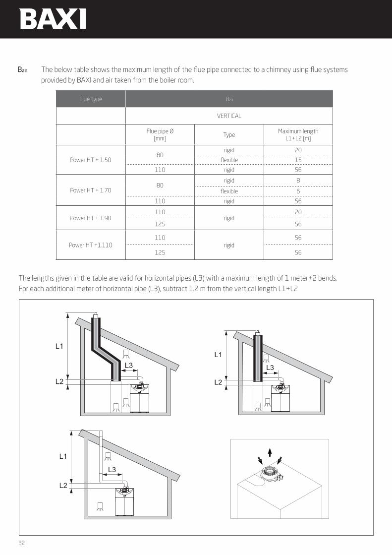
Flue type B23
VERTICAL
Flue pipe Ø[mm]
TypeMaximum length
L1+L2 [m]
Power HT + 1.5080
rigid 20
flexible 15
110 rigid 56
Power HT + 1.7080
rigid 8
flexible 6
110 rigid 56
Power HT + 1.90110
rigid20
125 56
Power HT +1.110110
rigid56
125 56
B23 The below table shows the maximum length of the flue pipe connected to a chimney using flue systems provided by BAXI and air taken from the boiler room.
The lengths given in the table are valid for horizontal pipes (L3) with a maximum length of 1 meter+2 bends. For each additional meter of horizontal pipe (L3), subtract 1.2 m from the vertical length L1+L2
L1
L2
L3
L1
L2
L3
L1
L2
L3
L1
L2
L3
L1
L2
L3
L1
L2
L3
L1
L2
L3
L1
L2
L3
L1
L2
L3
33
Power HT+
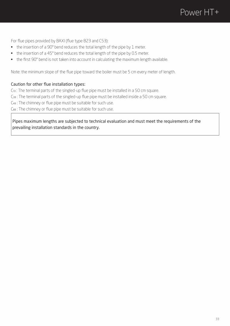
For flue pipes provided by BAXI (flue type B23 and C53):• the insertion of a 90° bend reduces the total length of the pipe by 1 meter.• the insertion of a 45° bend reduces the total length of the pipe by 0.5 meter.• the first 90° bend is not taken into account in calculating the maximum length available.
Note: the minimum slope of the flue pipe toward the boiler must be 5 cm every meter of length.
Caution for other flue installation types:C13 : The terminal parts of the singled-up flue pipe must be installed in a 50 cm square. C33 : The terminal parts of the singled-up flue pipe must be installed inside a 50 cm square. C43 : The chimney or flue pipe must be suitable for such use.C83 : The chimney or flue pipe must be suitable for such use.
Pipes maximum lengths are subjected to technical evaluation and must meet the requirements of the prevailing installation standards in the country.

34
Clearance dimensions
Power HT+ 1.50 - 1.70 Power HT+ 1.90 - 1.110
1000
250
250
1100
500
1127848
500
681
1100500
1000
320
681
The figure shows the minimum clearance dimensions to allow an easy access to the boiler and servicing.
Ventilazione da fornire alle caldaie
5.3.2 Spazio complessivo necessario per la caldaia
Per garantire una buona accessibilità all'apparecchio e facilitarne la manutenzione, lasciare sufficiente spazio intorno alla caldaia, secondo le informazioni fornite.
ImportanteLa caldaia deve essere accessibile in qualsiasi momento.
Spazio da fornire alle caldaie
Tab.14Modello di caldaia A B C D EPOWER HT+ 1.130 1100 500 400 800 1000POWER HT+ 1.150 1100 500 400 800 1000POWER HT+ 1.200 1100 500 750 800 1000POWER HT+ 1.250 1100 500 750 800 1000
Spazio da fornire alle caldaie dotate di kit del separatore idraulico, kit dello scambiatore a piastre o kit a cascata
Fig.21
MW-3000011-04
E
C
A
D
B
5 Prima dell'installazione
32 POWER HT + 7702635 - v02 - 11082018
Model A B C D E
POWER HT+ 1.130 1100 500 400 500 1000
POWER HT+ 1.150 1100 500 400 500 1000
POWER HT+ 1.200 1100 500 750 500 1000
POWER HT+ 1.250 1100 500 750 500 1000

35
Power HT+
Power HT+ 1.90 - 1.110
The table shows the diameters of the flue manifold and the flue for various configurations of boilers in cascade and for various heights of flue.
Remarks• distance of the manifold from the first boiler to the vertical chimney 2 meters;• shutter kit installed in each boiler in cascade;• the flue pipes and the connections between the flue manifold of the cascade and the chimney are not supplied by BAXI, also the manifolds for cascade installation with diameter bigger than 200 mm are not supplied by BAXI,• the calculation has been made assuming a PP “double wall” flue duct.
N° boilers in cascade
Power HT+1.50
Power HT+1.70
Power HT+1.90
Power HT+1.110
Power HT+1.130
Power HT+1.150
Power HT+1.200
Power HT+1.250
2
Nominal heat outputTotal 50°/30° C (kW)
100 140 180 220 260 300 400 500
Flue manifold Ø mm (A) 125 125 160 160 160 160Flue pipes to be sized
after technical evaluationand must meet therequirements of the
prevailing installationstandards in the country
Flue Ø mm (B) - H= 5-20 m 125 125 160 160 160 160
3
Nominal heat outputTotal 50°/30° C (kW)
150 210 270 330 390 450 600 750
Flue manifold Ø mm (A) 125 125 160 160 200 200Flue pipes to be sized
after technical evaluationand must meet therequirements of the
prevailing installationstandards in the country
Flue Ø mm (B) - H= 5-20 m 125 160 160 160 160 160
4
Nominal heat outputTotal 50°/30° C (kW)
200 280 360 440 520 600 800 1000
Flue manifold Ø mm (A) 125 160 200 200
Flue pipes to be sizedafter technical evaluation
and must meet therequirements of the
prevailing installationstandards in the country
Flue Ø mm (B) - H= 5-20 m 160 160 200 200
5
Nominal heat outputTotal 50°/30° C (kW)
250 350 450 550
Flue manifold Ø mm (A) 160 160 200 200
Flue Ø mm (B) - H= 5-20 m 160 200 200 200
6
Nominal heat outputTotal 50°/30° C (kW)
300 420 540 660
Flue manifold Ø mm (A) 160 200 200 200
Flue Ø mm (B) - H= 5-20 m 160 200 200 250
Flue systems - cascade installation

36
Boilers in cascade can be connected to a sole flue manifold with a shutter kit connection.The shutter kit connection is equipped with condensing trap and it has the following diameters: mod. 1.50-1.70 : 80/110 mm; mod 1.90-1.110: 110/110 mm.The graphs show the pressure drop of the flue manifold with shutter kit as a function of the heat output.
Pressure drop of the flue manifold with shutter kit 80/110
0,00
0,50
1,00
1,50
2,00
2,50
3,00
3,50
4,00
4,50
5,00
10 15 20 25 30 35 40 45 50 55 60 65 70 75 80 85 90 95 100 105 110
DP
[Pa]
Heat output [kW]
Pressure drop of the flue manifold with shutter kit 110/110
0
20
40
60
80
100
120
140
160
10 15 20 25 30 35 40 45 50 55 60 65 70 75 80 85 90 95 100 105 110
DP
[Pa]
Heat output [kW]

37
Power HT+
Maximum condensate water flow l/h 56
Max potentiality of the boiler kcal/h 300.000
Max potentiality of the boiler kW 350
Maximum working pressure bar 2
Maximum temperature of the water content °C Corresponding to the maximum temperatures of the condensate waters
Min/Max room temperature °C 5-40
Quantity of the first charge of product Kg 5
Next recharges Kg 4,5
Dimensions (hxwxd) mm 260x330x225
Neutralizer filter to process the water deriving from the condensation of BAXI condensing boilers in cascade installations.
Neutralizer kit for boilers up to 350 kWCode KHG 71412571
Recharge for neutralizer kit for boilers up to 350 kWCode KHG 71413541
Other accessories - cascade installation
38
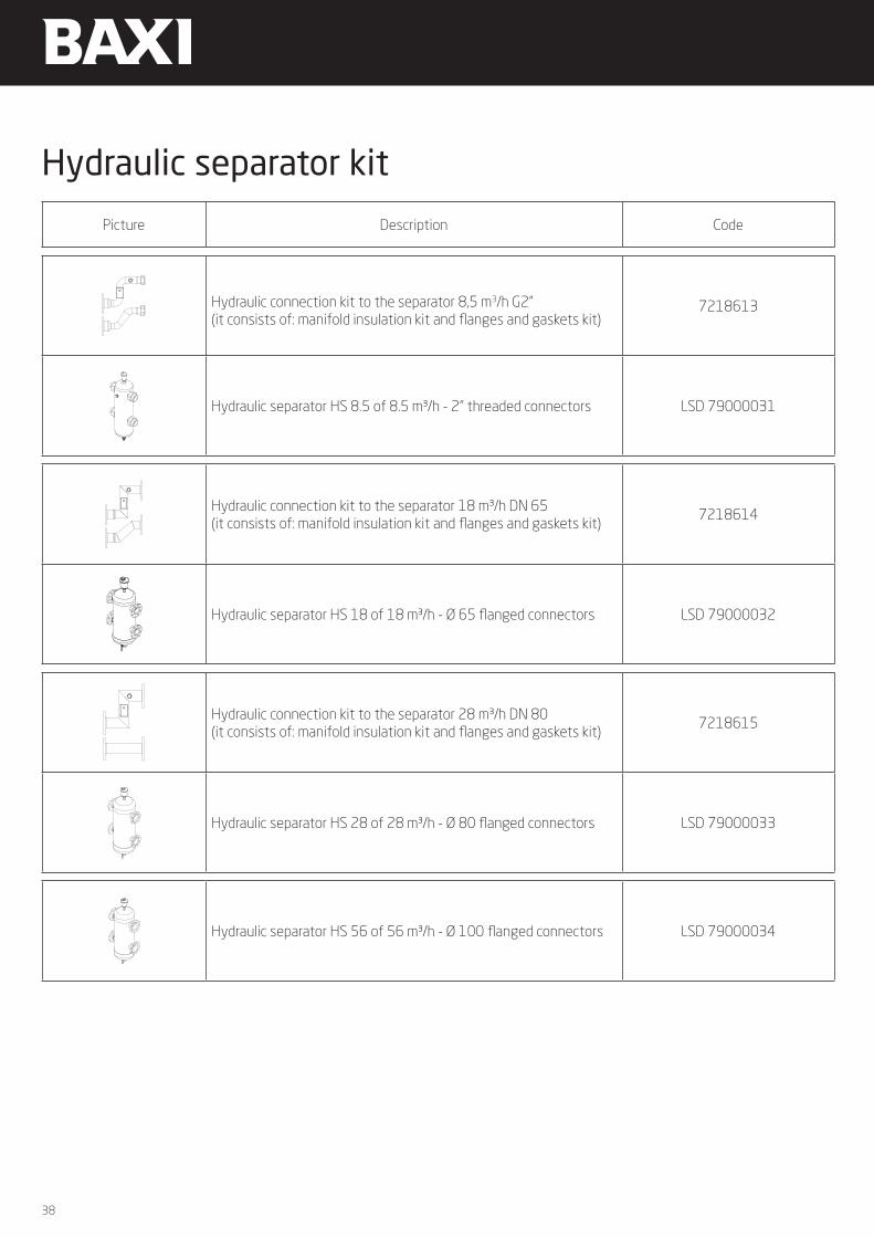
Picture Description Code
Hydraulic connection kit to the separator 8,5 m3/h G2”(it consists of: manifold insulation kit and flanges and gaskets kit)
7218613
Hydraulic separator HS 8.5 of 8.5 m³/h - 2” threaded connectors LSD 79000031
Hydraulic connection kit to the separator 18 m³/h DN 65(it consists of: manifold insulation kit and flanges and gaskets kit)
7218614
Hydraulic separator HS 18 of 18 m³/h - Ø 65 flanged connectors LSD 79000032
Hydraulic connection kit to the separator 28 m³/h DN 80(it consists of: manifold insulation kit and flanges and gaskets kit)
7218615
Hydraulic separator HS 28 of 28 m³/h - Ø 80 flanged connectors LSD 79000033
Hydraulic separator HS 56 of 56 m³/h - Ø 100 flanged connectors LSD 79000034
Hydraulic separator kit

39
Power HT+
Picture Description Code
Brazed exchanger SPS250 – 30 plates 7215320
Brazed exchanger SPS250 – 40 plates 7215321
Brazed exchanger SPS250 – 50 plates 7215322
Inspectable exchanger SPI3- 13 plates 7215323
Inspectable exchanger SPI3- 21 plates 7215324
Inspectable exchanger SPI3- 27 plates 7111961
Inspectable exchanger SPI3- 33 plates 7111962
Inspectable exchanger SPI3- 41 plates 7111964
Inspectable exchanger SPI3- 45 plates 7215325
Inspectable exchanger SPI3- 57 plates 7215326
Inspectable exchanger SPI3- 67 plates 7215327
Before the installation it is compulsory to choose the right exchanger that must be dimensioned, by a qualified person, according to the installation system and the legislation.
Plates exchangers

40
Picture Description Code
Mixing valve motor KHG 7140785
Mixing valve G1” KHG 7140783
Mixing valve G1/2” KHG 7140786
Mixing valve G3/4” KHG 7140787
Flow sensor for clip-in module THINK KHG 7140789
Hot water temperature sensor KHG 7140768
Sensor for solar controller LNC 7100000
Picture Description Code
LPG conversion kit for Power HT+ 1.50 7107186
LPG conversion kit for Power HT+ 1.70 7107188
LPG conversion kit for Power HT+ 1.90 7107189
LPG conversion kit for Power HT+ 1.110 7107190
Other accessoriesThermoregulation
LPG conversion kit

41
Power HT+

QualityEnvironment
Safetyare Baxi strategic aims and
the awarded certifications
ensure compliance with the
specific regulations
The Company assumes no responsibility for any possible contents mistakes, and reserves the right to make changes in products, due to technical or commercial demands, at any time without notice
Baxi S.p.A. 03-1909 G
36061 BASSANO DEL GRAPPA (VI)Via Trozzetti, [email protected]
QualityEnvironment
Safety