Power Consumption and Derating
32
Protection, Monitoring and Control Components for Low Voltage Equipment SELECTION GUIDE: INTERNATIONAL EDITION
Transcript of Power Consumption and Derating

Protection, Monitoring and Control Components for Low Voltage Equipment
SELECTION GUIDE: INTERNATIONAL EDITION
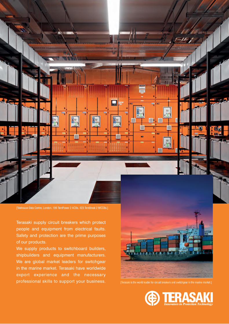
Terasaki supply circuit breakers which protect
people and equipment from electrical faults.
Safety and protection are the prime purposes
of our products.
We supply products to switchboard builders,
shipbuilders and equipment manufacturers.
We are global market leaders for switchgear
in the marine market. Terasaki have worldwide
export experience and the necessary
professional skills to support your business.
[Telehouse Data Centre, London. 199 TemPower 2 ACBs, 423 TemBreak 2 MCCBs.]
[Terasaki is the world leader for circuit breakers and switchgear in the marine market.]

CONTENTS
Terasaki Profile 4
Moulded Case Circuit Breakers 7
Electronic Protection Including Types with Monitoring and Communication 8
Adjustable Thermal and Adjustable Magnetic Protection 10
TemBreak 2 Lite 12
Circuit Breakers with Integral Residual Current Protection (CBR) 13
Moulded Case Circuit Breakers for Special Applications 14
MCCB Accessories 15
Air Circuit Breakers 16
ACB Selection Guide 17
Protection Relay Guide 18
ACB Accessories 19
Retrofit 20
Retrofit Concept 20
Retrofit Services 21
Advanced External Display and Protection Products 22
Monitoring and Communication: T2ED 22
Multi-Protection Relay: TemTrip 2 22
Contactors and Manual Motor Starters 23
Contactor Selection Guide 3P 24
Contactor Selection Guide 4P 26
MMS Selection Guide 28
DIN Modular Protection 29
Accessories 29
DIN Modular Protection Selection Guide 30
Automatic Transfer Controller 31
Contents | 3

HISTORY
Safety & Reliability High MTBF; Low MTTR; temperature monitoring, double control circuits
Approvals ISO 9001; ISO 14001; OHSAS 18001; Lloyds; BV; GL; GOST; SABS; DEKRA (KEMA); ASTA; IEC 60947-2; IEC 61439; IEC 60898
Asset Management Retrofits; Preventative Maintenance; Lifecycle Management
Special Protection Solutions DC; PV; UPS; 1000V AC; Integrated residual protection; 100kA and above
1933
1943
1963
1973
1983
1923
1923
1923
1963
1923
1970
1985
Terasaki Electric Works founded in Konohana-ku Osaka
PATENTED!Successfully developed the world’s first current-limiting breaker
Established our first overseas subsidiary in the UK
1953
We are meeting the needs of customers with a complete system of development, design and manufacture based on the know-how we have accumulated with electrics, electronics and control over the decades since our founding.
We have DEKRA (formerly KEMA) -approved test systems and two generators in house to carry out the necessary development tests.
Terasaki realises optimised products through 3D CAD, software development, mould and sheet metal design, structural design and resin flow analysis.
CAPABILITIES
R&D

PRODUCTS & SERVICES
Air Circuit Breakers
Moulded Case Circuit Breakers
Din Modular Protection
Automatic Transfer Controller
Din Modular Protection
Contactors
Asset Management
Retrofit
Safety & Reliability High MTBF; Low MTTR; temperature monitoring, double control circuits
Approvals ISO 9001; ISO 14001; OHSAS 18001; Lloyds; BV; GL; GOST; SABS; DEKRA (KEMA); ASTA; IEC 60947-2; IEC 61439; IEC 60898
Asset Management Retrofits; Preventative Maintenance; Lifecycle Management
Special Protection Solutions DC; PV; UPS; 1000V AC; Integrated residual protection; 100kA and above
1983
1993
2013
2023
2013
2023
2007
90 Years
100 Years
2000
PATENTED!Double contacts, double opening coils, double closing coils are unique to the TemPower 2 ACB
PATENTED! Residual current protection is an integrated feature of the TemBreak 2 CBR – the first in the world to meet IEC 60947-2, Annex B
PATENTED! The TemTrip relay was the first to offer true RMS protection
2003
It makes good environmental sense to install a product with a long life expectancy. If you install a Terasaki circuit breaker you can expect it to stay in service for a high number of electrical and mechanical operations.
The modular design of our Terasaki breakers allows component parts and accessories to be easily disassembled and separately disposed of. Moulded parts of MCCBs do not contain any embedded metal parts and are clearly marked to allow future identification for easy recycling.
Components with low weight and volume make life easy for users, but high performance from smaller products also means less material used and less waste produced.
SUSTAINABILITYExternal Display

TERASAKI PROFILE
Foundation: October 1, 1923
Established: April 1, 1980
Capital: 1236640 thousands of yen
Chairman: Masakazu Fujita
President: Taizo Terasaki
Number of Employees: 1914 (consolidated) 593 (non-consolidated)
Consolidated net sales: 36975 million yen
Non-consolidated net sales: 24680 million yen
Consolidated subsidiaries: 5 domestics and 8 overseas
Non-consolidated subsidiaries: 1 domestic and 2 overseas
Affiliated companies: 2 domestic
Listing: Tokyo Stock Exchange (Jasdaq)
[Security code 6637]
Mr. Masakazu Fujita Chairman
Mr. Taizo Terasaki President
Mr. Yasuhiko Terasaki Late chairman of the company
Mr. Yasutaro Terasaki Founder of the company
“We want to meet the needs of more customers
around the world in our circuit breaker and lifecycle
service businesses.” Mr. Taizo Terasaki, President
NUCLEAR POWER: Ringhals, Sweden
SOLAR POWER: South Italy
DESALINATION PLANT: Spain
MARINE: Oil Tanker “Belokamenka”, Russia
MINING: BHP Billiton, Australia
ALUMINIUM SMELTER: ALBA, Bahrain
OIL PRODUCTION: Sakhalin Island, Russia
DATA CENTRE: Telehouse London, UK
AUTOMOTIVE: Toyota ManufacturingPlant, Argentina
6 | Terasaki Profile
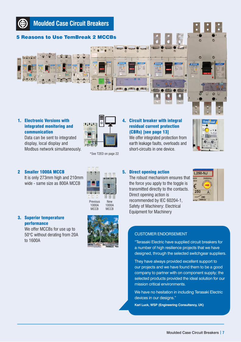
Moulded Case Circuit Breakers
1. Electronic Versions with integrated monitoring and communication Data can be sent to integrated display, local display and Modbus network simultaneously.
2 Smaller 1000A MCCB It is only 273mm high and 210mm wide - same size as 800A MCCB
3. Superior temperature performance We offer MCCBs for use up to 50°C without derating from 20A to 1600A
4. Circuit breaker with integral residual current protection (CBRs) [see page 13] We offer integrated protection from earth leakage faults, overloads and short-circuits in one device.
5. Direct opening action The robust mechanism ensures that the force you apply to the toggle is transmitted directly to the contacts. Direct opening action is recommended by IEC 60204-1, Safety of Machinery: Electrical Equipment for Machinery
5 Reasons to Use TemBreak 2 MCCBs
*See T2ED on page 22
Previous 1000A MCCB
New 1000A MCCB
Moulded Case Circuit Breakers | 7
CUSTOMER ENDORSEMENT
“Terasaki Electric have supplied circuit breakers for a number of high resilience projects that we have designed, through the selected switchgear suppliers.
They have always provided excellent support to our projects and we have found them to be a good company to partner with on component supply; the selected products provided the ideal solution for our mission critical environments.
We have no hesitation in including Terasaki Electric devices in our designs.”
Karl Luck, WSP (Engineering Consultancy, UK)

Electronic Protection Including Types with Monitoring and Communication
Frame Reference Quantity Unit Condition TB2 S/H/L 250Model S250 S250 S250 H250Type NE GE PE NENumber of Poles 3,4 3,4 3,4 3,4Nominal current ratings In (A) 50°C 40,125,160,250 40,125,160,250 40,125,160, 250 40,125,160, 250Monitoring and Communication l l l l
Electrical characteristicsRated Operational voltage Ue (V) AC 50/60 HZ 690 690 690 690 Rated insulation voltage Ui (V) 800 800 800 800Rated impulse withstand voltage Uimp (kV) 8 8 8 8Ultimate breaking capacity (IEC, JIS, AS/NZS)
Icu (kA) 690V AC 525V AC 440V AC 400/415V AC 220/240V AC
7.5 25 253665
7.5 25 506585
20 35 50 70 125
20 45 120 125 150
Service breaking capacity (IEC, JIS, AS/NZS)
Ics (kA) 690V AC 525V AC 440V AC 400/415V AC220/240V AC
7.5 25 253665
7.5 25 253685
15 35 50 70 125
15 45 80 85 150
Rated breaking capacity (NEMA) (kA) 480V AC 240V AC
25 65
25 65
35 125
45 150
Rated short-time withstand current Icw (kA) 0.3 sec – – – –Utilisation category A A A ADimensions
Height (mm) 165 165 165 165Width (mm) 3 Pole 105 105 105 105
4 Pole 140 140 140 140Depth (mm) 103 103 103 103Weight (kg) 3 Pole 2.5 2.5 2.5 2.5
4 Pole 3.3 3.3 3.3 3.3OperationEndurance Electrical cycles 415V AC 10,000
Mechanical cycles 30,000
Frame Reference Quantity Unit Condition TB2 H/L 800 TB2 1000Model H800 L800 S800 S800 S1000 S1000
Type NE NE NE RE SE NE
Number of Poles 3,4 3,4 3,4 3,4 3,4 3,4
Nominal current ratings In (A) 50°C 630,800 630,800 630,800 630,800 10008 10008
Monitoring and Communication l l l l l l
Electrical characteristicsRated Operational voltage Ue (V) AC 50/60 HZ 690 690 690 690 690 690
Rated insulation voltage Ui (V) 800 800 800 800 800 800
Rated impulse withstand voltage Uimp (kV) 8 8 8 8 8 8
Ultimate breaking capacity (IEC, JIS, AS/NZS)
Icu (kA) 690V AC 525V AC 440V AC 400/415V AC 220/240V AC
251 40 125125150
251 45 180200200
201 30 50 50 85
251 35 65 70 100
201 30 455085
251 45 65 70 100
Service breaking capacity (IEC, JIS, AS/NZS)
Ics (kA) 690V AC 525V AC 440V AC 400/415V AC220/240V AC
201 34 9494150
201 34 135150150
201 30 50 50 85
201 30 50 50 75
151 23 34 38 65
201 34 50 50 75
Rated breaking capacity (NEMA) (kA) 480V AC 240V AC
40 150
45 200
30 85
35 100
30 85
45 100
Rated short-time withstand current Icw (kA) 0.3 sec 10 10 10 10 – –
Utilisation category B B B B A A
DimensionsHeight (mm) 273 273 273 273 273 273
Width (mm) 3 Pole 210 210 210 210 210 210
4 Pole 280 280 280 280 280 280
Depth (mm) 140 140 103 103 103 103
Weight (kg) 3 Pole 6 6 4 4 11.0 11.0
4 Pole 7 7 5 5 14.8 14.8
OperationEndurance Electrical cycles 415V AC 4,000 4,000
Mechanical cycles 10,000 10,000– Not available • Optional 1 MCCB cannot be used in IT systems at this voltage 2100KA at 400V 375KA at 400V 48.7kg 630A, 9.1kg 800A 511.9kg 630A, 12.3kg 800A 613.3kg 630A, 14.8kg 800A 716.8kg 630A, 18.8kg 800A 8Not fully rated at 50oC. Contact Terasaki
Electrical Characteristics to IEC 60947-2, EN 60947-2, JIS C 8201-2-1 ANN.1, AS/NZS 3947-2, NEMA AB-1
8 | Moulded Case Circuit Breakers

TB2 H/L 400 TB2 E/S 630H400 L400 S400 S400 S400 E630 S630 S630NE NE NE GE PE NE CE GE3,4 3,4 3,4 3,4 3,4 3,4 3,4 3,4250, 400 250, 400 250,400 250,400 250,400 630 630 630
l l l l l l l l
690 690 690 690 690 690 1 690 1 690 1
800 800 800 800 800 800 800 8008 8 8 8 8 8 8 835 45 120125150
50 65 180200200
20 30 455085
20 30 6570100
20 30 80 85 100
10 1 15 253650
20 1 30 455085
20 1 30 6570100
35 45 8085150
50 65 135150150
15 30 455085
15 30 505085
15 30 80 85 85
10 1 15 25 36 50
15 1 30 455085
15 1 30 50 50 85
45 150
65 200
25 85
30 100
30 100
15 50
25 85
30 100
5 5 5 5 5 – – –B B B B B A A A
260 260 260 260 260 260 260 260140 140 140 140 140 140 140 140185 185 185 185 185 185 185 185140 140 103 103 103 103 103 1037.1 7.1 4.3 4.3 4.3 5.0 5.0 5.09.4 9.4 5.7 5.7 5.7 6.5 6.5 6.5
4,500 4,50015,000 15,000
TB2 1250 TB21600S1250 S1250 S1250 S1600 S1600SE NE GE SE NE3,4 3,4 3,4 3,4 3,41250 1250 1250 1600 1600– – – – –
690 690 690 690 690800 800 800 800 8008 8 8 8 8201 30 45 50 85
251 45 6570100
451 65 85100/852
125
201 30 455085
451 65 85100/852
125151 23 343865
201 34 505075
341 50 6575/653
94
151 23 343865
341 50 6575/653
9430 85
45 100
65 125
30 85
65 125
15 15 15 20 20B B B B B
370 370 370 370 370210 210 210 210 210280 280 280 280 280120 120 120 140 14019.8 19.8 19.8 27.0 27.025.0 25.0 25.0 35.0 35.0
4,000 2,0005,000 5,000
– Not available • Optional 1 MCCB cannot be used in IT systems at this voltage 2100KA at 400V 375KA at 400V 48.7kg 630A, 9.1kg 800A 511.9kg 630A, 12.3kg 800A 613.3kg 630A, 14.8kg 800A 716.8kg 630A, 18.8kg 800A
Moulded Case Circuit Breakers | 9
MCC
BS u
p to
320
0A a
re a
vaila
ble.
Con
tact
Ter
asak
i for
det
ails
.
Electronic overload protection is adjustable from 40% to
100% of rated current.
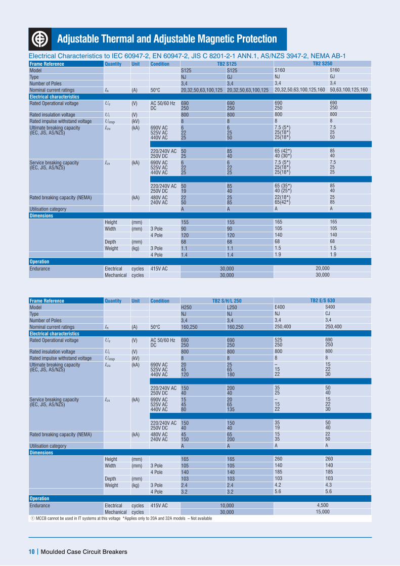
Adjustable Thermal and Adjustable Magnetic Protection
Frame Reference Quantity Unit Condition TB2 S125 TB2 S250Model S125 S125 S160 S160
Type NJ GJ NJ GJ
Number of Poles 3,4 3,4 3,4 3,4
Nominal current ratings In (A) 50°C 20,32,50,63,100,125 20,32,50,63,100,125 20,32,50,63,100,125,160 50,63,100,125,160Electrical characteristicsRated Operational voltage Ue (V) AC 50/60 Hz
DC690 250
690 250
690 250
690 250
Rated insulation voltage Ui (V) 800 800 800 800
Rated impulse withstand voltage Uimp (kV) 8 8 8 8
Ultimate breaking capacity (IEC, JIS, AS/NZS)
Icu (kA) 690V AC 525V AC 440V AC 400/415V AC 220/240V AC 250V DC
6 22 253650 25
6 25 506585 40
7.5 (5*) 25(18*) 25(18*)36 (30*)65 (42*) 40 (30*)
7.5 25 506585 40
Service breaking capacity (IEC, JIS, AS/NZS)
Ics (kA) 690V AC 525V AC 440V AC 400/415V AC220/240V AC 250V DC
6 22 2536/3050 19
6 22 2536/3385 40
7.5 (5*) 25(18*) 25(18*)36 (25*)65 (35*) 40 (25*)
7.5 25 253685 40
Rated breaking capacity (NEMA) (kA) 480V AC 240V AC
22 50
25 85
22(18*) 65(42*)
25 85
Utilisation category A A A A
DimensionsHeight (mm) 155 155 165 165
Width (mm) 3 Pole 90 90 105 105
4 Pole 120 120 140 140
Depth (mm) 68 68 68 68
Weight (kg) 3 Pole 1.1 1.1 1.5 1.54 Pole 1.4 1.4 1.9 1.9
OperationEndurance Electrical cycles 415V AC 30,000 20,000
Mechanical cycles 30,000 30,000
Frame Reference Quantity Unit Condition TB2 S/H/L 250 TB2 E/S 630Model H250 L250 E400 S400
Type NJ NJ NJ CJ
Number of Poles 3,4 3,4 3,4 3,4
Nominal current ratings In (A) 50°C 160,250 160,250 250,400 250,400Electrical characteristicsRated Operational voltage Ue (V) AC 50/60 Hz
DC690 250
690 250
525 250
690 250
Rated insulation voltage Ui (V) 800 800 800 800
Rated impulse withstand voltage Uimp (kV) 8 8 8 8
Ultimate breaking capacity (IEC, JIS, AS/NZS)
Icu (kA) 690V AC 525V AC 440V AC 400/415V AC220/240V AC 250V DC
20 45 120125150 40
25 65 180200200 40
– 15 222535 25
15 22 303650 40
Service breaking capacity (IEC, JIS, AS/NZS)
Ics (kA) 690V AC 525V AC 440V AC 400/415V AC220/240V AC 250V DC
15 45 8085150 40
20 65 135150150 40
– 15 222535 19
15 22 303650 40
Rated breaking capacity (NEMA) (kA) 480V AC 240V AC
45 150
65 200
15 35
22 50
Utilisation category A A A A
DimensionsHeight (mm) 165 165 260 260Width (mm) 3 Pole 105 105 140 140
4 Pole 140 140 185 185Depth (mm) 103 103 103 103Weight (kg) 3 Pole 2.4 2.4 4.2 4.3
4 Pole 3.2 3.2 5.6 5.6OperationEndurance Electrical cycles 415V AC 10,000 4,500
Mechanical cycles 30,000 15,000 1 MCCB cannot be used in IT systems at this voltage *Applies only to 20A and 32A models – Not available
Electrical Characteristics to IEC 60947-2, EN 60947-2, JIS C 8201-2-1 ANN.1, AS/NZS 3947-2, NEMA AB-1
10 | Moulded Case Circuit Breakers

TB2 S250 TB2 S/H/L 250S250 S250 H125 L125 H160 L160
NJ GJ NJ NJ NJ NJ3,4 3,4 3,4 3,4 3,4 3,4
160,200,250 160,200,250 20,32,50,63,100,125 20,32,50,63,100,125 160 160
690 250
690 250
690 250
690 250
690 250
690 250
800 800 800 800 800 800
8 8 8 8 8 87.5 25 253665 40
7.5 25 506585 40
20 45 120125150 40
25 65 180200200 40
20 45 120125150 40
25 65 180200200 40
7.5 25 253665 40
7.5 25 253685 40
15 45 8085150 40
20 65 135150150 40
15 45 8085150 40
20 65 135150150 40
22 65
25 85
45 150
65 200
45 150
65 200
A A A A A A
165 165 165 165 165 165105 105 105 105 105 105140 140 140 140 140 140
68 68 103 103 103 1031.5 1.5 2.4 2.4 2.5 2.5
1.9 1.9 3.2 3.2 3.3 3.3
10,000 30,000 20,00030,000 30,000 30,000
TB2 E/S 630 TB2 1000S400 S400 S400 S800 S800 S800
NJ GJ PJ CJ NJ PJ3,4 3,4 3,4 3,4 3,4 3,4
250,400 250,400 250,400 630,800 630,800 630,800
690 250
690 250
690 250
690 250
690 250
690 250
800 800 800 800 800 800
8 8 8 8 8 82O 30 455085 40
20 30 6570100 40
20 30 8085100 40
101 151 303650 50
201 30 505085 50
251 45 6570100 50
15 30 455085 40
15 30 505085 40
15 30 808585 40
101 151 303650 50
201 30 505085 50
201 34 505075 50
25 85
30 100
30 100
15 50
30 85
65 200
A A A A A A
260 260 260 273 273 273
140 140 140 210 210 210
185 185 185 280 280 280
103 103 103 103 103 1034.2 4.2 4.2 8.5 8.5 8.55.6 5.6 5.6 11.5 11.5 11.5
4,500 4,000
15,000 10,000
Electrical Characteristics to IEC 60947-2, EN 60947-2, JIS C 8201-2-1 ANN.1, AS/NZS 3947-2, NEMA AB-1
Moulded Case Circuit Breakers | 11
Thermal protection is adjustable from 63% to 100% of rated current.

TemBreak 2 Lite Electrical Characteristics to IEC 60947-2, EN 60947-2, JIS C 8201-2-1 ANN.1, AS/NZS 3947-2, NEMA AB-1
12 | Moulded Case Circuit Breakers
Frame Reference Quantity Condition TB2 Lite 250Model E250 E250 E250 E250 S250 S250Type SCF SCJ SF SJ SF SJNumber of Poles 3, 4 3, 4 3, 4 3, 4 3, 4 3, 4Nominal current ratings In 50°C 125,150,175,
200,225,250100,125,160, 200,250
125,150,175, 200,225,250
100,125, 160, 200,250
125,150,175, 200,225,250
160,200,250
Electrical characteristicsRated Operational voltage UE (V) AC 50/60 Hz
DC525 250 525 250 525 250 525 250 690 250 690 250
Rated insulation voltage Ui (V) 690 800 690 800 690 800Rated impulse withstand voltage Uimp (kV) 8 8 8 8 8 8Ultimate breaking capacity (IEC, JIS, AS/NZS)
Icu (kA) 690V AC 525V AC 440V AC400/415C AC220/240V AC 250V DC
– 6 10 16 25 13
– 6 10 16 25 13
– 7.5 15 25 35 15
– 7.5 15 25 35 15
4 10 30 40 85 25
4 10 30 40 85 25
Service Breaking Capacity (IEC, JIS, AS/NZS)
Ics (kA) 690V AC 525V AC 440V AC400/415C AC220/240V AC 250V DC
– 3 5 8 13 7
– 3 5 8 13 7
– 6 12 19 27 12
– 6 12 19 27 12
4 7.5 15 20 43 13
4 7.5 15 20 43 13
Rated breaking capacity (NEMA) (kA) 480V AC 240V AC
6 25
6 25
10 35
10 35
25 85
25 85
ProtectionFixed Thermal, fixed magnetic q – q – q –Adjustable thermal, adjustable magnetic – q – q _ q
DimensionsHeight (mm) 165 165 165 165 165 165Width (mm) 3 Pole (4 Pole) 105 (140) 105 (140) 105 (140) 105 (140) 105 (140) 105 (140)Depth (mm) 68 68 68 68 68 68
Weight Weight (kg) 3 Pole (4 Pole) 1.5 (1.9) 1.5 (1.9) 1.5 (1.9) 1.5 (1.9) 1.5 (1.9) 1.5 (1.9)Endurance
Electrical 415V 6,000Mechanical 18,000
– Not available q Standard 1 14,000<125A
Frame Reference Quantity Condition TB2 Lite 160Model E160 E160 E160 S160 S160 S160 S160 S160Type SF SF SJ SCF SCJ SHJ SF SJNumber of Poles 1 3,4 3,4 3,4 3, 4 3, 4 3, 4 3, 4Nominal current ratings In (A) 50°C 16,20,25,32,
40,50, 63,80, 100,125
16,20,25,32, 40,50,63,80, 100,125,160
20,40,63, 80,100, 125,160
16,20,25,32, 40,50,63,80, 100,125,160
25,40,63,80, 100,125, 160
25,40,63, 80,100, 125,160
16,20,25, 32, 40,50,63,80, 100,125,160
25,40,63,80, 100,125, 160
Electrical characteristicsRated Operational voltage Ue (V) AC 50/60 Hz
DC240 –
525 250
525 250
525 250
525 250
525 250
690 250
690 250
Rated insulation voltage Ui (V) 690 690 690 690 690 690 690 690Rated impulse withstand voltage Uimp (kV) 8 8 8 8 8 8 8 8Ultimate breaking capacity (IEC, JIS, AS/NZS)
Icu (kA) 690V AC 525V AC 440V AC400/415V AC220/240V AC 250V DC
– – – – 25 –
– 6 10 16 25 13
– 6 10 16 25 13
– 7.5 15 25 35 20
– 7.5 15 25 35 20
– 7.5 7.5 25 35 20
6 10 25 40 50 25
6 10 25 40 50 25
Service Breaking Capacity (IEC, JIS, AS/NZS)
Ics (kA) 690V AC 525V AC 440V AC400/415C AC
220/240V AC 250V DC
– – – – 13 –
– 3 5 8 13 7
– 3 5 8 13 7
– 4 7.5 13 18 10
– 4 7.5 13 18 10
– 4 4 25 25 10
3 7.5 13 20 25 13
3 7.5 13 20 25 13
Rated breaking capacity (NEMA) (kA) 480V AC 240V AC
– 25
6 25
6 25
7.5 35
7.5 35
– _
10 50
10 50
ProtectionFixed Thermal, fixed magnetic q q – q – – q –Adjustable thermal, fixed magnetic – – q – q q – q
DimensionsHeight (mm) 130 130 130 130 130 130 130 130Width (mm) 3 Pole (4 Pole) 25 (1P) 75, (100) 75, (100) 75, (100) 75, (100) 75, (100) 75, (100) 75, (100)Depth (mm) 68 68 68 68 68 68 68 68Weight (kg) 3 Pole (4 Pole) 0.3 (1P) 0.8 (1.0) 0.8 (1.0) 0.8 (1.0) 0.8 (1.0) 0.8 (1.0) 0.8 (1.0) 0.8 (1.0)
EnduranceElectrical 415V 10,000 10,0001
Mechanical 20,000 20,000

Circuit Breakers with Integral Residual Current Protection (CBR)
When CBR is used as the supply connection device and is set to 30 mA, RCBOs are not required on outgoing load circuits for electric shock protection (unless discrimination is required).The residual current protection provided by the supply connection device covers all load circuits. MCBs may be used to protect load circuits and the installation will still meet the requirements for electric shock protection “RCD”
How can a CBR give me a cost advantage?Integral CBR – “circuit breakers… which
incorporate the residual current function as an integrated feature”:
IEC 60947-2 Annex B.In other words a CBR is a moulded-case
circuit breaker equivalent of a DIN-modular
RCBO – it includes overload, short-circuit and
residual current protection inside a single
device.
What is a CBR?
Electrical Characteristics to IEC 60947-1, IEC 60947-2, IEC 60947-2 ANNEXEB, IEC 60755
Moulded Case Circuit Breakers | 13
Frame Reference Quantity Unit Condition TB2 S125 TB2 S250Model ZE125 ZS125 ZS125 ZE250 ZS250 ZS250Type NJ NJ GJ NJ NJ GJNumber of Poles 3,4 3,4 3,4 3,4 3,4 3,4Nominal current ratings In (A) 50°C 20,32,50,63,
100,12520,32,50,63, 100,125
20,32,50,63, 100,125
160,250 160,250 160,250
Electrical characteristicsRated Operational voltage Ue (V) AC 50/60 HZ 525 525 525 525 525 525Rated insulation voltage Ui (V) 525 525 525 525 525 525Rated impulse withstand voltage Uimp (kV) 8 8 8 8 8 8Ultimate breaking capacity (IEC, JIS, AS/NZS)
Icu (kA) 525V AC 440V AC400/415V AC 220/240V AC
8 152535
22 253650
25 506585
10 152535
25 253665
25 506585
Service breaking capacity (IEC, JIS, AS/NZS)
Ics (kA) 525V AC 440V AC 400/415V AC220/240V AC
6 121927
22 2536/3050
22 2536/3385
7.5 121927
25 253665
25 253685
ProtectionAdjustable thermal, fixed magnetic, residual/earth leakage
q q q q q q
DimensionsHeight (mm) 155 155 155 165 165 165Width (mm) 3 Pole 90 90 90 105 105 105
4 Pole 120 120 120 140 140 140Depth (mm) 68 68 68 68 68 68Weight (kg) 3 Pole 1.1 1.1 1.1 1.5 1.5 1.5
4 Pole 1.4 1.4 1.4 1.9 1.9 1.9OperationEndurance Electrical cycles 415V AC 30,000 10,000
Mechanical cycles 30,000 10,000– Not available q Standard
Residual current protection settings: 30mA, 100mA, 300mA, 500mA,
1000mA and 3000mA.

Moulded Case Circuit Breakers for Special Applications
High performance at the distribution voltages found in marine applications. Terasaki supply more switchgear to ships than any other manufacturer worldwide.
Circuit Breakers with Icu=70kA at 690V AC
Every frame size includes a switch-disconnector version without integral protection. Internal and external accessories are compatible with switch-disconnector versions.
Switch-Disconnectors
1000V AC is used as a distribution voltage where long cables are necessary. This product range is ideal for mines and railways.
Circuit Breakers for 1000V AC
The available short-circuit output of generators is lower than typical transformers. Sometimes MCCBs with sensitive instantaneous protection are necessary for use with generators.
Low Instantaneous
We have developed special version of MCCBs to protect systems with DC voltages above 250V. Our range extends to 1000V DC and are often used to protect solar energy plants.
Circuit Breakers and Switch Disconnectors up to 1000V DC
14 | Moulded Case Circuit Breakers

MCCB Accessories
Moulded Case Circuit Breakers | 15
Terminal
Block
Neutral Link
Alarm Switches
Handle Lock
Auxiliary Contacts
Terminal Covers for front Connection
Terminal Covers for Rear Connection and Plug-in
Extension Bars
Rear Connections
Plug-in Base
Din Rail Adaptor
Interpole Barriers
Door Flange
Slide Type Mechanical Interlock
Link Type Mechanical Interlock*
Wire Type Mechanical Interlock*
OCR Checker
Door Mounting Handle
Door Interlocking Handle
Motor Operator
Terminal Covers for Cable Clamps
Terminal temperature monitor and
alarm
Cable Clamps
Shunt Trip
UVT
*Compatible with motor operator or either handle.
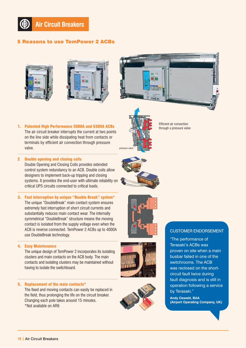
Air Circuit Breakers
5 Reasons to use TemPower 2 ACBs
1. Patented High Performance 5000A and 6300A ACBs The air circuit breaker interrupts the current at two points on the line side while dissipating heat from contacts or terminals by efficient air convection through pressure valve.
2 Double opening and closing coils Double Opening and Closing Coils provides extended control system redundancy to an ACB. Double coils allow designers to implement back-up tripping and closing systems. It provides the end-user with ultimate reliability on critical UPS circuits connected to critical loads.
3. Fast interruption by unique “Double Break” system* The unique “DoubleBreak” main contact system ensures extremely fast interruption of short circuit currents and substantially reduces main contact wear. The internally symmetrical “DoubleBreak” structure means the moving contact is isolated from the supply voltage even when the ACB is reverse connected. TemPower 2 ACBs up to 4000A use DoubleBreak technology.
4. Easy Maintenance The unique design of TemPower 2 incorporates its isolating clusters and main contacts on the ACB body. The main contacts and isolating clusters may be maintained without having to isolate the switchboard.
5. Replacement of the main contacts* The fixed and moving contacts can easily be replaced in the field, thus prolonging the life on the circuit breaker. Changing each pole takes around 15 minutes. *Not available on AR6
Efficient air convection through a pressure valve
CUSTOMER ENDORSEMENT
“The performance of Terasaki’s ACBs was proven on site when a main busbar failed in one of the switchrooms. The ACB was reclosed on the short-circuit fault twice during fault diagnosis and is still in operation following a service by Terasaki.”
Andy Oswald, BAA (Airport Operating Company, UK)
pressure valve
16 | Air Circuit Breakers

Air Circuit Breakers Selection Guide
Frame Reference Quantity Unit Condition AR2 AR3 AR4 AR6ACB Model AR208, AR212,
AR216AR208, AR212, AR216, AR220
AR212, AR216, AR220
AR325, AR332
AR325, AR332
AR440 AR650, AR663
Type D S H S H SB SNumber of Poles 3, 4 3, 4 3, 4 3, 4 3, 4 3, 4 3, 4Nominal Current Ratings In A 800,1000,1250,
1600800,1000,1250, 1600,2000
1250,1600, 2000
2500,2000 2500,2000 4000 5000,6300
Electrical CharacteristicsRated Operational Voltage
Ue V 690 690 690 690 690 690 690
Rated Insulation Voltage
Ui V 1000 1000 1000 1000 1000 1000 1000
Rated Impulse Withstand Voltage
Uimp kV 12 12 12 12 12 12 12
Ultimate Breaking Capacity
Icu kA 690V AC 422 502 55 652 85 852 852
440V AC 50 65 80 85 100 100 120 400/415V AC 50 65 80 85 100 100 120 250V DC1 40 40 40 40 40 40 40Service Breaking Capacity
Ics kA 690V AC 322 502 55 652 85 852 852
440V AC 36 65 80 85 100 100 120 400/415V AC 36 65 80 85 100 100 120 250V DC1 40 40 40 40 40 40 40Making Capacity Icm kA 690V AC 882 1052 121 143 187 1872 1872
440V AC 105 143 176 187 220 220 264 400/415V AC 105 143 176 187 220 220 264Rated Short-time Withstand Current
Icw kA 1 Second 50 65 80 85 100 100 120
3 Seconds 36 50 55 65 75 75 85Breaking Time seconds 0.03 0.03 0.03 0.03 0.03 0.03 0.05Spring Charging Time seconds 10 10 10 10 10 10 10Closing Time seconds 0.08 0.08 0.08 0.08 0.08 0.08 0.08Utilisation Category B B B B B B BDimensionsFixed Type Height mm 460 460 460 460 460 – – Width mm 3 pole 360 360 360 466 466 – – Width mm 4 Pole 445 445 445 586 586 – – Depth mm 290 290 290 290 290 – – Weight kg 3 pole 53 54 54 80 80 Weight kg 4 Pole 59 60 60 92 92Drawout Type Height mm 460 460 460 460 460 460 460 Width mm 3 pole 354 354 354 460 460 460 799 Width mm 4 Pole 439 439 439 580 580 580 1034 Depth mm 345 345 345 345 345 345 380 Weight kg 3 pole
Drawout73 79 79 105 105 126 200
Weight kg 4 Pole Drawout
86 94 94 125 125 158 285
Endurance Mechanical Cycles With
maintenance26000 30000 30000 20000 20000 15000 10000
Mechanical Cycles Without maintenance
12500 15000 15000 10000 10000 8000 5000
Electrical Cycles Without maintenance at 440V AC
11000 12000 12000 7000 7000 3000 1000
Electrical Cycles With maintenance at 440V AC
26000 30000 30000 20000 20000 15000 10000
Notes1. Special versions are available for use at 600V and 800V DC. Contact us for details2. Not applicable in unearthed (IT) systems
TemPower 2 ACB
Air Circuit Breakers | 17

Protection Relay Guide
TemPower 2 is available with a choice of flexible IDMT protection curves to assist in selectivity applications.
S.I. Standard Inverse
V.I. Very Inverse
E.I. Extremely Inverse All these curves are user definable and comply with IEC 60255-3.
TemPower 2 may be equipped with an optional communication interface unit that allows data exchange with a host PC via a Modbus open network. Data communicated includes measurements, fault log, maintenance information, ON/OFF status, settings and control (ON/OFF/RESET) signals.
Protection Functions Dial Adjustment
L – Long TimeS – Short Time I – Instantaneous
Optional Protection Functions Unrestricted Ground Fault Neutral Protection
AGR-11B
Protection Functions LCD Ammeter
L – Long TimeS – Short Time I – Instantaneous Pre-Trip (load shedding) Fault Indication ContactsOptional Protection Functions Ground Fault (Unrestricted or Restricted) Neutral Protection Communication Phase Rotation Protection Generator Protection Curves IDMT Protection Curves Field Test
AGR-21B
Protection Functions Back-Lit Energy Meter
L – Long TimeS – Short Time I – Instantaneous Pre-Trip (load shedding) Fault Indication ContactsOptional Protection Functions Ground Fault (Unrestricted or Restricted) Neutral Protection Under/Over Voltage Alarm Reverse Power Zone Interlocking Contact Temperature Monitoring Communication Phase Rotation Protection Under/Over Frequency Earth Leakage Harmonic Monitoring Generator Protection Curves IDMT Protection Curves Field Test
AGR-31B
18 | Air Circuit Breakers
Non-Automatic (switch-disconnector) versions without protection are available in every frame size.
t
S.I.V.I.
I3t
I4t
E.I.
Inverse Definite Minimum Time (I.D.M.T)
Commercial gateway or PLC
Communication network
RS485
Host Network
Host PC

ACB Accessories
Air Circuit Breakers | 19
Position Switches
Open / Close Counter
IP55 Transparent Cover
UndervoltageTrip
Capacitor Shunt Trip 48V DC
Shunt Trip Closing Coil
IP3X Chassis Protection CoverLifting Plates
Fixing Bolts (For Draw Out ACBs)
Storage Draw Out Handle
Lifter Loader Protection Relay Checker
Test Jumper Step Down Transformer
440V to 220V
Mechanical Interlock, Key Interlock,
Castell Interlock
Auto Spring Discharge Device
Interpole Barriers
Trip Indicator SwitchSpring Status Switch
Motor Operator
Tropicalisation, Anti-Corrosion, Cold Climate treatments
IP31 Door Flange
Auxiliary Switches
Host PC
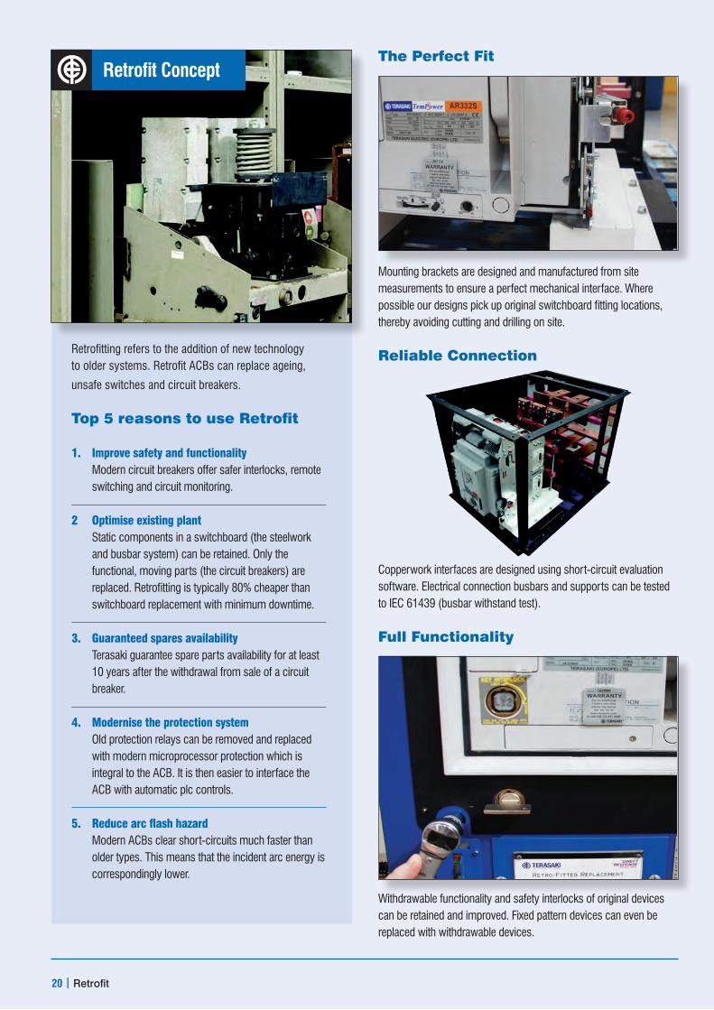
Retrofit Concept
Retrofitting refers to the addition of new technology to older systems. Retrofit ACBs can replace ageing,
unsafe switches and circuit breakers.
Top 5 reasons to use Retrofit
1. Improve safety and functionality Modern circuit breakers offer safer interlocks, remote switching and circuit monitoring.
2 Optimise existing plant Static components in a switchboard (the steelwork and busbar system) can be retained. Only the functional, moving parts (the circuit breakers) are replaced. Retrofitting is typically 80% cheaper than switchboard replacement with minimum downtime.
3. Guaranteed spares availability Terasaki guarantee spare parts availability for at least 10 years after the withdrawal from sale of a circuit breaker.
4. Modernise the protection system Old protection relays can be removed and replaced with modern microprocessor protection which is integral to the ACB. It is then easier to interface the ACB with automatic plc controls.
5. Reduce arc flash hazard Modern ACBs clear short-circuits much faster than older types. This means that the incident arc energy is correspondingly lower.
The Perfect Fit
Mounting brackets are designed and manufactured from site measurements to ensure a perfect mechanical interface. Where possible our designs pick up original switchboard fitting locations, thereby avoiding cutting and drilling on site.
Reliable Connection
Copperwork interfaces are designed using short-circuit evaluation software. Electrical connection busbars and supports can be tested to IEC 61439 (busbar withstand test).
Full Functionality
Withdrawable functionality and safety interlocks of original devices can be retained and improved. Fixed pattern devices can even be replaced with withdrawable devices.
20 | Retrofit

Retrofit Services
Tested to current standardASTA tested to IEC 61439 for short-circuit withstand (lcw)GEC MPact Ellison English Electric
Low voltage arc hazard reduction1. Remove switching
using umbilical cord controller
2. Faster opening time reduces incident arc energy. TemPower 2 ACB can be set to open a short-circuit in less than 30 milliseconds (typically at least twice as fast as the device it will replace).
Modern protectionThe AGR Protection relay can replace the functions of several devices in an existing switchboard to provide:• restricted earth fault
protection• overcurrent protection• data communication
to BMS or SCADA• plc control
Terasaki’s Retrofit Services
We prefer to conduct a site survey for every retrofit project - even if the breaker to be replaced is already on our design database. This ensures that the installation is as quick as possible, with minimum disruption to the client’s supply.
Mechanical and electrical interfaces are modelled using state-of-the-art 3-D CAD.
We can arrange for busbar interface connections to the switchboard to be independently short-circuit tested. This provides reassurance to the client that the fault capability of the retrofitted circuit breakers and connections will equal or exceed that of the original system.
Manufacture, assembly and routine testing is carried out at Terasaki’s facility in Glasgow, Scotland. The factory and processes are certified to the ISO 9001 quality management standard.
Our engineers are renowned for fast and efficient working. Some of our Retrofit designs can be installed without a shutdown. Where this is not possible, our team will ensure that disruption is minimised.
Retrofit | 21
We design retrofit ACBs on request. If you are interested in a brand which is not shown below we would be happy to examine it. New designs are continually added to our portfolio. Check the latest list on the Terasaki website: www.terasaki.co.uk
TerasakiEllisonGECMerlin GerinSiemensUnelecSquare DMitsubishiSaceABBHyundaiAEGEnglish ElectricMEMKlockner Moeller
Advanced External Display and Protection Products
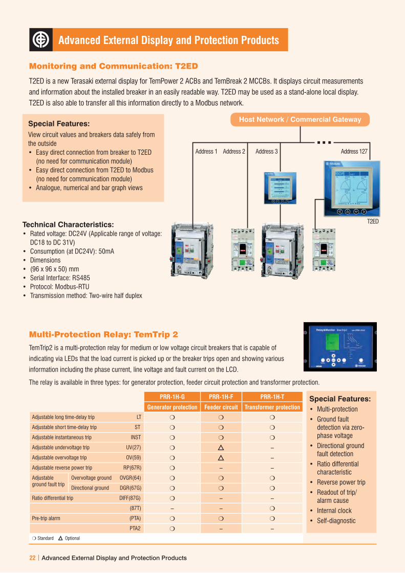
Special Features:View circuit values and breakers data safely from the outside• Easy direct connection from breaker to T2ED
(no need for communication module)• Easy direct connection from T2ED to Modbus
(no need for communication module)• Analogue, numerical and bar graph views
Technical Characteristics:• Rated voltage: DC24V (Applicable range of voltage:
DC18 to DC 31V)• Consumption (at DC24V): 50mA• Dimensions• (96 x 96 x 50) mm• Serial Interface: RS485• Protocol: Modbus-RTU• Transmission method: Two-wire half duplex
Monitoring and Communication: T2ED
T2ED is a new Terasaki external display for TemPower 2 ACBs and TemBreak 2 MCCBs. It displays circuit measurements and information about the installed breaker in an easily readable way. T2ED may be used as a stand-alone local display.T2ED is also able to transfer all this information directly to a Modbus network.
Multi-Protection Relay: TemTrip 2
TemTrip2 is a multi-protection relay for medium or low voltage circuit breakers that is capable of
indicating via LEDs that the load current is picked up or the breaker trips open and showing various
information including the phase current, line voltage and fault current on the LCD.
The relay is available in three types: for generator protection, feeder circuit protection and transformer protection.
PRR-1H-G PRR-1H-F PRR-1H-T
Generator protection Feeder circuit Transformer protection
Adjustable long time-delay trip LT m m m
Adjustable short time-delay trip ST m m m
Adjustable instantaneous trip INST m m m
Adjustable undervoltage trip UV(27) m –
Adjustable overvoltage trip OV(59) m –
Adjustable reverse power trip RP(67R) m – –
Adjustable ground fault trip
Overvoltage ground OVGR(64) m m m
Directional ground DGR(67G) m m m
Ratio differential trip DIFF(87G) m – –
(87T) – – m
Pre-trip alarm (PTA) m m m
PTA2 m – –m Standard Optional
Special Features:• Multi-protection• Ground fault
detection via zero-phase voltage
• Directional ground fault detection
• Ratio differential characteristic
• Reverse power trip• Readout of trip/
alarm cause• Internal clock• Self-diagnostic
Host Network / Commercial Gateway
Address 1 Address 2 Address 3 Address 127
T2ED
22 | Advanced External Display and Protection Products

TemContact 2 Contactors
TemContact 2 is a range of magnetic contactors and thermal overload relays. Current ratings from 6A to 800A are available in 9 frame sizes and in 3 or 4 pole versions.
TemContact 2 has upgraded insulation voltage (increased from 690 to 1000V AC) impulse withstand voltage (increased from 6 to 8kV) in contactors over 40A.
Optional Accessories:
• Auxiliary contacts
• Surge absorption unit
• Reversing connection kit
• Mechanical interlock
• Safety cover for front of mechanism
• Overload relays
• Remote mounting kit for overload relay
• Pre-loading resistors for capacitor switching
• Mechanical latch
• Remote reset device for overload relays
TemContact 2 Manual Motor Starters
TemContact 2 Manual Motor Starters have integrated short-circuit and overload protection for motors of up to 45kW at 400V AC.
There are three frame sizes, each with three versions which cover the range:
• TMS32S, TMS63S, TMS100S – standard short-circuit performance
• TMS32H, TMS63H, TMS100H – high short-circuit performance
• TMS32HI, TMS63HI, TMS100HI – high short-circuit performance, without overload protection
Optional Accessories:
• Auxiliary switches for front- and side-mounting
• Alarm switches
• Shunt trip
• Undervoltage Trip
• Direct connection adapter for TemContact 2 contactors up to 100A
Contactors and Manual Motor Starters
Contactors and Manual Motor Starters | 23

Contactor Selection Guide 3P
TK Type Thermal Overload relays
Model Parameter Unit TC-9b TC-12b TC-18b TC-22b TC-32a TC-40a TC-50a TC-65a
Frame size 22 AF 40 AF 65 AF
Current and power ratings
Thermal current AC1 A 25 25 40 40 50 60 70 100
Switching power 200/240V AC3 kW 2.5 3.5 4.5 5.5 7.5 11 15 18.5
Switching current 200/240V AC3 A 11 13 18 22 32 40 55 65
Switching power 380/440V AC3 kW 4 5.5 7.5 11 15 18.5 22 30
Switching current 380/440V AC3 A 9 12 18 22 32 40 50 65
Switching power 500/550 AC3 kW 4 7.5 7.5 15 18.5 22 30 33
Switching current 500/550 AC3 A 7 12 13 20 28 32 43 60
Switching power 690V AC3 kW 4 7.5 7.5 15 18.5 22 30 33
Switching current 690V AC3 A 6 9 9 18 20 23 28 35
Electrical characteristics
Rated operational voltage Ue V 690 690 690
Rated insulation voltage Ui V 690 1000 1000
Rated frequency f Hz 50/60 50/60 50/60
Rated impulse withstand voltage Uimp kV 6 8 8
Operation
Maximum operating rateEndurance
AC3 ops/hr 1800 1800 1800
Mechanical million 15 15 12
Electrical million 2.5 2.5 2
Dimensions
AC Control Weight kg 0.34 0.55 1.05
Size (WxHxD) mm 45 x 73.5 x 86 69 x 83 x 93 79 x 106 x 119
DC Control Weight kg 0.51 0.77 1.3
Size (WxHxD) mm 45 x 73.5 x 104 69 x 83 x 120 79 x 106 x 147
Nema size 00 00 0 1 1 1 2 2
Auxiliary Contacts
Auxiliary Contacts (included as Standard)
1N0 1NC 2N0 2NC 2N0 2NC
Model Parameter Unit TK-32 TK-32 TK-63
Electrical Characteristics
Rated operational voltage, Ue V 690 690 690
Rated insulation voltage Ui V 690 690 690
Rated impulse withstand voltage Uimp kV 6 6 6
Setting range
Setting range A 0.1~40 0.1~40 4~65
Trip class 10A,20 10A,20 10A,20
Dimensions
Weight kg 0.17 0.17 0.31/0.33
Size (WxHxD) mm 45 x 75 x 90 45 x 75 x 90 55 x 81 x 100
24 | Contactors and Manual Motor Starters

TC-75a TC-85a TC-100a TC-130a TC-150a TC-185a TC-225a TC-265a TC-330a TC-400a TC-500a TC-630a TC-800a
100 AF 150 AF 225 AF 400 AF 800 AF
110 135 160 160 210 230 275 300 350 450 580 660 900
22 25 30 37 45 55 75 80 90 125 147 190 220
75 85 105 130 150 185 225 265 330 400 500 630 800
37 45 55 60 75 90 132 147 160 200 265 330 440
75 85 105 130 150 185 225 265 330 400 500 630 800
37 45 55 60 70 110 132 147 160 225 265 330 500
64 75 85 90 100 180 200 225 280 350 400 500 720
37 45 55 55 55 110 140 160 200 250 300 400 500
42 45 65 60 60 120 150 185 225 300 380 420 630
690 690 690 690 690
1000 1000 1000 1000 1000
50/60 50/60 50/60 50/60 50/60
8 8 8 8 8
1800 1200 1200 1200 1200
12 5 5 5 2.5 2.5
2 1 1 1 0.5 0.5
1.9 2.4 5.4 9.2 22.4
94 x 140 x 137 119 x 158 x 132 138 x 203 x 185 163 x 243 x 205 285 x 312 x 245
2.8 2.3 5.4 9.2 22.4
94 x 140 x 172.3 119 x 158.5 x 132 138 x 203 x 185 163 x 243 x 205 285 x 312 x 245
2 3 3 3 4 4 4 5 5 5 6 6 7
2N0 2NC 2N0 2NC 2N0 2NC 2N0 2NC 2N0 2NC
TK-95 TK-150 TK-225 TK-400 TK-800
690 690 690 690 690
690 690 690 690 690
6 6 6 6 6
7~100 34~150 64~240 85~400 200~800A
10A,20 10A,20 10A,20 10A,20 10A,20
0.48/0.5 0.67 2.5 2.6 11.5
70 x 97 x 110 95 x 109 x 113 147 x 141 x 184 151 x 171 x 198 860 x 530 x 212
Contactors and Manual Motor Starters | 25
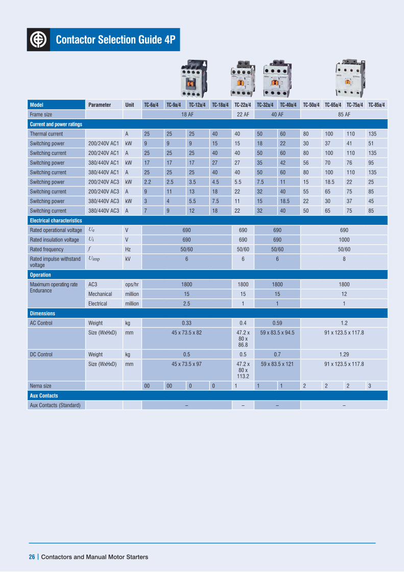
Contactor Selection Guide 4P
TK Type Thermal Overload relays
Model Parameter Unit TC-6a/4 TC-9a/4 TC-12a/4 TC-18a/4 TC-22a/4 TC-32a/4 TC-40a/4 TC-50a/4 TC-65a/4 TC-75a/4 TC-85a/4
Frame size 18 AF 22 AF 40 AF 85 AF
Current and power ratings
Thermal current A 25 25 25 40 40 50 60 80 100 110 135
Switching power 200/240V AC1 kW 9 9 9 15 15 18 22 30 37 41 51
Switching current 200/240V AC1 A 25 25 25 40 40 50 60 80 100 110 135
Switching power 380/440V AC1 kW 17 17 17 27 27 35 42 56 70 76 95
Switching current 380/440V AC1 A 25 25 25 40 40 50 60 80 100 110 135
Switching power 200/240V AC3 kW 2.2 2.5 3.5 4.5 5.5 7.5 11 15 18.5 22 25
Switching current 200/240V AC3 A 9 11 13 18 22 32 40 55 65 75 85
Switching power 380/440V AC3 kW 3 4 5.5 7.5 11 15 18.5 22 30 37 45
Switching current 380/440V AC3 A 7 9 12 18 22 32 40 50 65 75 85
Electrical characteristics
Rated operational voltage Ue V 690 690 690 690
Rated insulation voltage Ui V 690 690 690 1000
Rated frequency f Hz 50/60 50/60 50/60 50/60
Rated impulse withstand voltage
Uimp kV 6 6 6 8
Operation
Maximum operating rateEndurance
AC3 ops/hr 1800 1800 1800 1800
Mechanical million 15 15 15 12
Electrical million 2.5 1 1 1
Dimensions
AC Control Weight kg 0.33 0.4 0.59 1.2
Size (WxHxD) mm 45 x 73.5 x 82 47.2 x 80 x 86.8
59 x 83.5 x 94.5 91 x 123.5 x 117.8
DC Control Weight kg 0.5 0.5 0.7 1.29
Size (WxHxD) mm 45 x 73.5 x 97 47.2 x 80 x
113.2
59 x 83.5 x 121 91 x 123.5 x 117.8
Nema size 00 00 0 0 1 1 1 2 2 2 3
Aux Contacts
Aux Contacts (Standard) – – – –
26 | Contactors and Manual Motor Starters

TC-100/4 TC-130a/4 TC-150a/4 TC-185a/4 TC-225a/4 TC-265a/4 TC-330a/4 TC-400a/4 TC-500a/4 TC-630a/4 TC-800a/4
225 AF 400 AF 800 AF
160 165 250 300 330 360 420 500 650 750 900
57 60 76 87 100 115 135 160 245 255 310
150 155 200 230 260 300 350 420 630 660 800
106 110 142 165 185 215 250 300 450 470 570
150 155 200 230 260 300 350 420 630 660 800
30 37 95 55 75 80 90 125 147 190 220
105 125 150 185 225 265 330 400 500 630 800
55 60 75 90 132 147 160 200 265 330 440
105 120 150 185 225 265 330 400 500 630 800
690 690 690
1000 1000 1000
50/60 50/60 50/60
8 8 8
1200 1200 1200
15 15 12
0.8 0.5 2.5
5.6 9.9 26.3
175 x 203 x 185
206 x 243 x 205 346 x 310 x 244
5.6 9.9 26.3
175 x 203 x 185
206 x 243 x 205 346 x 310 x 244
3 3 4 4 4 5 5 5 6 6 7
2N02NC 2N02NC 2N02NC
Contactors and Manual Motor Starters | 27

Manual Motor Starters Selection GuideIn accordance with IEC 60947 - 2 & IEC 60947 - 4 - 1Manual Motor StartersModel Parameter Unit Power rating
at 400V AC (kW)
TMS -32S TMS -32H TMS -32HI*
Breaking Capacity @ 400/415V AC Icu / Ics (kA) TMS -32S
Breaking Capacity @ 400/415V AC Icu / Ics (kA) TMS -32H/HI
TMS -63S TMS -63H TMS -63HI*
Breaking Capacity @ 400/415V AC Icu / Ics (kA) TMS -63S
Breaking Capacity @ 400/415V AC Icu/Ics (kA) TMS -63H/HI
TMS -100S TMS -100H TMS -100HI*
Breaking Capacity @ 400/415V AC Icu / Ics (kA) TMS -100S
Breaking Capacity @ 400/415V AC Icu / Ics (kA) TMS -100H/HI
Number of poles 3 3 3
Frame size 32AF 63AF 100AF
Current and Power
Rated operational current Ie (A) 0.02 0.1 ~ 0.16 100/100 100/100
(underlined) and 0.06 0.16 ~ 0.25 100/100 100/100
protection setting range 0.09 0.25 ~ 0.4 100/100 100/100
0.12 0.4 ~ 0.63 100/100 100/100
0.25 0.63 ~ 1.0 100/100 100/100
0.55 1.0 ~ 1.6 100/100 100/100
0.75 1.6 ~ 2.5 100/100 100/100
1.5 2.5 ~ 4 100/100 100/100
2.2 4 ~ 6 100/100 100/100
3 5 ~ 8 100/100 100/100
4 6 ~ 10 50/38 100/100 6 ~ 10 100/100 100/100
5.5 9 ~ 13 50/38 100/100 9 ~ 13 50/38 100/100
7.5 11 ~ 17 20/15 50/38 11 ~ 17 25/19 50/50 11 ~ 17 50/38 100/100
7.5 14 ~ 22 15/11 50/38 14 ~ 22 25/19 50/50 14 ~ 22 50/38 100/50
11 18 ~ 26 15/11 50/38 18 ~ 26 25/19 50/50 18 ~ 26 50/38 100/50
15 22 ~ 32 15/11 50/38 22 ~ 32 25/19 50/50 22 ~ 32 50/38 100/50
18.5 28 ~ 40 10/8 40/30 28 ~ 40 25/19 50/50 28 ~ 40 50/38 100/50
22 34 ~ 50 25/19 50/50 34 ~ 50 50/38 100/50
30 45 ~ 63 25/19 50/50 45 ~ 63 50/38 100/50
30 47 ~ 65 25/19 35/27
37 55 ~ 75 50/38 75/50
45 70 ~ 90 50/38 75/50
45 80 ~ 100 50/38 75/50
Electrical Characteristics
Rated operational voltage Ue V 690 690 690
Rated insulation voltage Ui V 690 690 1000
Rated frequency f Hz 50/60 50/60 50/60
Rated impulse withstand Uimp kV 6 8 8
Utilisation category IEC 60 947 - 2 (Breaker) Cat. A Cat. A Cat. A
IEC 60 947 - 4 (Motor Starter) AC 3 AC 3 AC 3
Protection
Thermal magnetic (Except HI = Magnetic only)
Operation
Endurance Mechanical 100,000 50,000 50,000
Electrical 100,000 25,000 25,000
Max operating frequency per hour
25 25 25
Weight g 320 360 1000
Handle Type Rocker Rotary Rotary Rotary
Terminal Screw Lug Lug
Accessories
Optional ( auxiliary , alarm contacts) yes yes yes
* TMS-**HI models have no overload protection or protection setting range. Rated operational current, Ie, (underlined) applies to TMS-**HI models
28 | Contactors and Manual Motor Starters

Accessories
Din Modular Protection
Safety and protection are the prime purposes of Terasaki products. Our range of DIN modular Protection products covers ratings from 0.5A to 125A and includes:
- Circuit breakers for overload and short-circuit protection,
- Residual current devices for the prevention of electric shock and fires,
- Circuit breakers combining overload, short-circuit and residual current protection.
With more than 500 items in the range, there is a solution for most applications.
A Auxiliary contact 1NO, 1NC. 6A, 230V AC. Not suitable for TD3RCCB
B Alarm contact, 1NO, 1NC. 6A, 230V AC. Not suitable for TD3RCCB
C RCCB switch. Combined auxiliary contact (1NO, 1NC, 6A, 230V AC) + Alarm contact (1NO, 1NC, 6A, 230V AC)
D Shunt trip. RCCB switch (C) must be fitted before fitting the shunt trip to the TD3RCCB
E Undervoltage trip. RCCB switch (C) must be fitted before fitting the shunt trip to the TD3RCCB
F Overvoltage trip. Rated voltage, Un, 230V AC. Opens the circuit breaker if supply voltage exceeds 280V AC. RCCB switch (C) must be fitted before fitting the shunt trip to the TD3RCCB
G Padlock. Suitable for TD3 M06, M10, XA (open and closed) and for TD31P1M (in open position only)
H Residual current block for TD3 M06 and M10
I Rotary handle for TD3 ICP
A B C D E F G H I
DIN Modular Protection | 29

Din Modular Protection Selection Guide
Miniature Circuit Breakers Type MCB MCB MCB MCB MCB
Model Quantity Unit TD3 M06 TD3 M10 TD3 1P1M TD3 XA TD3 ICP
Poles (Modules) 1 (1), 1+N (2), 2 (2),
3 (3), 3+N(4), 4 (4)
1 (1), 1+N (2), 2 (2),
3 (3), 3+N(4), 4 (4)
1+N (1) 1 (1.5), 2 (3), 3 (4.5),
4 (6)
1 (1), 2 (2), 3 (3), 4 (4)
Electrical Characteristics
Standard IEC/EN 60898 IEC/EN 60898 IEC/EN 60898 IEC/EN 60898
IEC/EN 60947-2
UNE EN 20317
Nominal Rated Current In A 6, 10, 16, 20, 25, 32, 40,
50, 63
0.5*, 1*, 2*, 3*, 4*, 6, 10,
16, 20, 25, 32, 40, 50, 63
6, 10, 16, 20, 25, 32, 40 80, 100, 125 5, 7.5, 10, 15, 20, 25, 30, 35, 40,
45, 50, 63
Rated Voltage Ue V 230/400 - 240/415 230/400 - 240/415 230/400 - 240/415 230/400 - 240/415 230/400 - 240/415
Rated Frequency Hz 50/60 50/60 50/60 50/60 50/60
Breaking Capacity Icn (Icu) kA 6 10 6 10 (10) 6
Protection
Thermal- Magnetic Characteristic Type B, C B, C, D B, C C, D UNE EN 20317
Connection
Rigid Conductor Terminal mm2 25 35 16 70 25
Flexible Conductor Size 16 25 10 35 16
Dimensions
Per Module HxDxW mm 85 x 74 x 17.5 84 x 74 x 17.5 84 x 74 x 17.5 90 x 72 x 26.5 85 x 74 x 17.5
*Only for “D” type
Residual Current Devices and Modular SwitchesType RCCB RCCB RCBO RCBO Modular Switch
Model Quantity Unit TD3 RCCB TD3 RCCB TD3 RCBO TD3 RCBO TD3 MS
Poles (Modules) 2 (2) 4 (4) 1+N (1) 1+N (2) 1 (1), 2 (2), 3 (3), 4 (4)
Electrical Characteristics
Standard IEC/EN 61008 IEC/EN 61008 IEC/EN 61009 IEC/EN 61009 IEC EN 60947-3
Rated Sensitivity (I n) mA 30 100 300 30 100 300 30 30
Nominal Rated Current In A AC
type
25, 40,
63, 100
40,
63
25, 40,
63
25, 40,
63, 80,
100
63,
100
25, 40,
63, 80,
100
6 - 40 6 - 40 32 63 100 125
In A A
type
25, 40,
63
– – 40,
100
– – – – –
In A S
type
– – – – – 40,
100
– – –
In A Ai
type
25, 40,
63
– – 40 – – – – –
In A S-Ai
type
– – 40, 63 – – 40,
100
– – –
Rated Voltage Un V 230/ 400 - 240/ 415 230/400 - 240/415 230 - 240 230/400 - 240/415 230/400 - 240/415
Breaking Capacity Icn (Im) (1.5) (1.5) 10 10 – – – –
Energy Withstand (EN 61008) I2t kA2s > 22.5 > 22.5 – – – – – –
Peak Current Withstand (EN 61008) I peak kA > 3.3 > 3.3 – – – – – –
Short-circuit Withstand Capacity Icw (rms) kA – – – – 0.48 0.94 1.2 1.5
Rated Frequency Hz 50/60 50/60 50/60 50/60 50/60
Protection
Thermal-Magnetic Characteristic Type – – B, C C – – – –
Connection
Rigid Conductor Terminal mm2 25 25 16 25 25 50 50 50
Flexible Conductor Size mm2 16 16 10 16 16 35 35 35
Dimensions
Per module H x D x W mm 87.5 x 71 x 17.5 87.5 x 71 x 17.5 115 x 72 x 17.5 85.4 x 72 x 17.5 83 x 72 x 17.5
30 | DIN Modular Protection

TemTransfer 2 Automatic Changeover Controller for TemPower 2 ACBs, TemBreak 2 MCCBs and TemContact 2 Contactors
TemTransfer 2 is fully configurable Automatic Changeover Controller (ACC) for use in standby power applications. The module will monitor the voltage and frequency of the incoming AC mains (utility) supply and in the event of a failure will issue a start command to the generator control system.
The controller (ACC) is designed to monitor the incoming AC mains supply (1 or 3 phases) for under/over voltage and under/over frequency. Should any of the parameters fall out of limit, the module will issue a command to the generating set controller. Once the generator set is available and producing an output within limits, TemTransfer 2 will control the circuit breaker or contactor and switch the load from the mains (utility) to the generating set.
When the mains (utility) supply returns to within limits, the module will command a return to the mains (utility) supply and shut down the generator after a suitable cooling run. Various timing sequences are available to prevent nuisance starting unnecessary supply breaks.
TemTransfer 2 Product Features
TemTransfer 2’s back-lit LCD shows system status and indicates any system warnings via a 4 line text display. Red and green LEDs indicate the operational status of the network. The module can be easily configured by using TemTransfer 2 Configuration Suite PC Software, via an interface kit (optional).
Supporting many different topologies, configurable timers, volt-free digital inputs and outputs make the TemTransfer 2 controller a fully flexible solution to suit a wide variety of applications.
TemTransfer 2 Specifications
Automatic Transfer Controller
• Back-lit LCD with 4 line text display• Real time clock• PC / Front panel• Volt-free relays• Configurable timers
• 5 configurable outputs• 10 configurable outputs• Event log• Auto start inhibit• Load inhibit
Generator
Schematic Diagram: Automatic Changeover with TemTransfer 2 and TemBreak 2 Interlocked MCCBs
MainsSTATUS
STATUS
STATUS ON/OFF
START
Automatic Transfer Controller | 31

CAT REF. 15-G00EN
©Copyright Terasaki Electric (Europe) Ltd 2015
Ratings and specifications are subject to change without notice.
www.terasaki.com
TERASAKI ELECTRIC (EUROPE) LTD. 80 Beardmore Way, Clydebank Industrial Estate, Clydebank, Glasgow, G81 4HT, Scotland (UK) Telephone: 44-141-941-1940 Fax: 44-141-952-9246 Email: [email protected] http://www.terasaki.com
TERASAKI MIDDLE EAST Saif Zone Q3-168, PO Box 120860 Sharjah, UAE Telephone: 971-56-676-4825 Fax: 976-655-78141 Email: [email protected] http://www.terasaki.com
TERASAKI ELECTRIC (EUROPE) LTD. (FILIALE ITALIA) Via Ambrosoli, 4A-20090, Rodano, Milano, Italy Telephone: 39-02-92278300 Fax: 39-02-92278320 Email: [email protected] http://www.terasaki.it
TERASAKI ELECTRIC (EUROPE) LTD. (SUCURSAL EN ESPAÑA) Pol. Ind. Coll de la Manya, C/Cal Ros dels Ocells 5 08403 Granollers , (Barcelona) España Telephone: 34-93-879-60-50 Fax: 34-93-870-39-05 Email: [email protected] http://www.terasaki.es
TERASAKI ELECTRIC (EUROPE) LTD. (FILIAL SVERIGE) Box 2082 Flygfältsgatan 12, SE-128 22 Skarpnäck Telephone: 46-8-556-282-30 Fax: 46-8-556-282-39 Email: [email protected] http://www.terasaki.se
TERASAKI CIRCUIT BREAKERS (S) PTD. LTD. 17 Tuas Street, Singapore, 638454 Telephone: 65-6744-9752 Fax: 65-6748-7592 Email: [email protected]
TERASAKI ELECTRIC CO., LTD. Head Office, 7-2-10 Hannancho, Abenoku, Osaka, Japan Circuit Breaker Division: 7-2-10 Kamihigashi, Hiranoku Osaka, Japan Telephone: 81-6-6791-9323 Fax: 81-6-6791-9274 Email: [email protected] http://www.terasaki.co.jp
TERASAKI ELECTRIC (M) SDN, BHD. Lot 3, Jalan 16/13D, 40000 Shah Alam, Selangor Darul Ehsan, Malaysia Telephone: 60-3-5549-3820 Fax: 60-3-5549-3960 Email: [email protected]
TERASAKI DO BRASIL LTDA. Rua Cordovil, 259-Parada De Lucas, 21250-450, Rio De Janeiro-R.J., Brazil Telephone: 55-21-3301-9898 Fax: 55-21-3301-9861 Email: [email protected] http://www.terasaki.com.br
TERASAKI ELECTRIC (CHINA) LTD. 72 Pacific Industrial Park, Xin Tang Zengcheng, Guangzhou 511340, China Telephone: 86-20-8270-8556 Fax: 86-20-8270-8586 Email: [email protected]
TERASAKI ELECTRIC GROUP SHANGHAI REPRESENTATIVE OFFICE Room No. 1405-6, Tomson Commercial Building, 710 Dong Fang Road, Pudong, Shanghai, 200122, China Telephone: 86-21-58201611 Fax: 86-21-58201621 Email: [email protected]