NDW2-1600 - SisconNDW2-1600 Dimension NDW2-1600 Wiring Aperture of Cabinet Door and Installing Holes...
41
NDW2-1600 Shanghai Liangxin Electrical CO.,LTD Address: No. 668 Heng An Road, Pu Dong New District, Shanghai Post code: 200137 Tel: 86-21-50412789 Fax: 86-21-58675966 E-mail: [email protected] As standards, specifications and designs change from time to time, please ask for confirmation of the information given in this publication. 2010 - Liangxin Electrical - All rights reserved 2010.10 Intelligent Air Circuit Breaker
Transcript of NDW2-1600 - SisconNDW2-1600 Dimension NDW2-1600 Wiring Aperture of Cabinet Door and Installing Holes...

NDW2-1600
Shanghai Liangxin Electrical CO.,LTDAddress: No. 668 Heng An Road, Pu Dong New District, Shanghai Post code: 200137Tel: 86-21-50412789Fax: 86-21-58675966E-mail: [email protected]
As standards, specifications and designs changefrom time to time, please ask for confirmationof the information given in this publication.
201
0 -
Lian
gxin
Ele
ctri
cal -
All
righ
ts r
eser
ved
2010.10
Intelligent Air Circuit Breaker

Application
Model and Implication
Standards
Working Condition
Product StructureGeneral Structure
Structure of Drawout ACB
Main SpecificationsIntelligent Control UnitOperation Panel
Menu StructureStructure of Measurements Menu
Structure of Parameters Setting Menu
Structure of Protection Setting Menu
Structure of Records and Maintenances Menu
05
05
06
06
0606
07
070808
1010
14
15
17
Leading• Low-voltage• Electrical• Component• Manufacturer
NDW2-1600 Intelligent Air Circuit Breaker

Theme MenuController FunctionsBasic Functions
Communication Function
Zone Interlocking and Signal Unit Function
Additional Functions
Controller Technical ParametersPower Supply
Input and Output
Anti-interference Performance
Functions Instruction and Parameters SettingProtection Function
Measurement Function
Maintenance Function
Accessory of Control Unit
181919
19
19
20
2020
21
21
2222
39
43
48
AccessoryElectrical Accessory
Mechanical Accessory
NDW2-1600 DimensionNDW2-1600 WiringAperture of Cabinet Door and Installing Holes DiameterElectrical Wiring DiagramsBasic OperatingPower Consumption, Derating Coefficient and Copper Bus SizeInstallation NoticeFault Analysis and Trouble ShootingAppendix: Tripping CurvesOrder Form
5151
52
54555657586162636576

NDW2-1600 Air Circuit Breaker
Product Structure
ND W 2 1600
W Air Circuit Breaker
1600 A
NDW2-1600
2
M: Standard type H: High breaking capacity type
No code: Fixed type C: Drawout type
200, 400, 630, 800, 1000, 1250, 1600
3 , 4
3M: Basic type 3H: Communication type
Grade of breaking capacity
Mounting type
Rated current
Number of poles
Control unit type
Frame size
05 06
Model and Implication
Application
NDW2 series air circuit breaker (hereinafter “ACB”), of which rated operational voltage is 400V/690V and rated current is up to 1600A, is used in AC 50Hz distribution network for power distribution and circuit and equipments protection against overload. undervoltage, short-circuit and grounding fault. ACB adopts the control units which can provide precise selective protection and with multifunction. It is especially suit for distribution network which requires to improve reliability of power supply and avoid unnecessary power failure. Besides that, 3H control unit is with communication interface for connection with fieldbus to realize remote control, remote-adjust, remote-meter and remote-information, which can meet the requirements of automatic control. Leakage protection can also be realized when ACB is matched with leakage transformer and corresponding control unit.
Meanwhile, it can also be used as switch-disconnector. The corresponding symbol is shown as“ ”.
4
Front Face Indication of Fixed ACB
General Structure
Standards
IEC 60947-1 and GB 14048.1. Low-voltage switchgear and controlgear - Part 1: General rules
IEC 60947-2 and GB 14048.2. Low-voltage switchgear and controlgear - Part 2: Circuit-breakers
IEC 60947-4-1 and GB 14048.4. Low-voltage switchgear and controlgear - Part 4-1: Contactors and motor-starters - Electromechanical contactors and motor-starters
Working Condition
Normal working ambient temperature: -5℃~ +40℃. The average temperature in 24 hours does not exceed +35℃. (Note: If the ambient temperature is beyond the range of normal working ambient temperature, user should consult with the manufacturer.)
Altitude: ≤2000m
Humidity: The relative humidity of the air does not exceed 50% at the temperature of +40℃. Higher relative humidity is permitted at lower temperature, such as 90% relative humidity at 20℃. Special measures are necessary in case of occasional condensation due to variations in temperature .
Pollution degree: 3.
Protection degree: IP40 (installing inside cubicle and with door frame).
Utilisation catagory: B
Installation catagory: IV for main circuits of ACB, coils of undervoltage release and primary coil of transformer. III for other auxiliary circuits and control circuits.
Installation condition: Vertical tilting angle should no more than 5°.
Transport and storage temperature: -25℃~ +55℃. +70℃ is acceptable in short time (24 hours).
Service place should be without explosive media, gas and dust which are corrosive and conductive.
Nameplate of auxiliary circuit terminalsMain contact position indicatorFixed bracketIntelligent control unitSpring energy storage indicatorManual energy storage indicatorClosing push-buttonOpening push-buttonTerminals of auxiliary circuitFault trip indicator/Re-set push-button
12345678910
Front Face Indication of Drawout ACB
Terminals of auxiliary circuitCradleMain contact position indicatorIntelligent control unitPosition locking deviceUnlock button of position locking deviceFunctional position indicator“Connected”, “Test”and“Disconnected”Racking handleSpring energy storage indicatorManual energy storage indicatorClosing push-buttonOpening push-buttonFault trip indicator/Re-set push-button
1234567
8910111213
6 7 8 9
6789
1
1
2
2
3
3
4
4
5 6
1213
10 89
6
7
11 10
9
5
7 8
No. ImplicationBrand code
Product code
Design code

07 08
Frame size (A) Inm
Rated current (A) ln
Rated operational voltage (V) Ue
Rated insulation voltage (V) Ui
Rate impulse withstand voltage (kV) Uimp
Number of poles
Grade of breaking capacity
Rated ultimate breaking capacity (kA, rms) Icu
Rated service breaking capacity (kA, rms) Ics
Rated short-time withstand current (kA) Icw
Total breaking time (ms, without additional time-delay)
Closing time (ms)
Dimension (mm)
NDW2
1600
200、400、630、800、1000、1250、1600
400、690
1000
12
3P、4P
12~18
≤60
6000
10000
20000
357×254×300
357×324×300
357×266×199
357×336×199
Structure of Drawout ACB
Terminals of auxiliary circuit
Safety Shield
Intelligent control unit
Manual operation mechanism
Auxiliary switch
Closing release
Motor for electrical charging
Terminals of auxiliary circuit
Shunt release
1
2
3
4
5
6
7
8
9
Cradle
ACB itself
Type
Electrical endurance
Mechanical endurance
Drawout type
Fixed type
3P
4P
3P
4P
(H×W×D)
H
65/35
55/35
42/35
M
50/25
50/25
42/25
Main Specifications
Operation Panel
Intelligent Control Unit
1
567
2
3
4
9 8
w
H
D
0.5s 1s
1
23
4
5
6
7
16
8 9 10 11
12 13 14 15
Endurance(times)
w/o maintenance
w/maintenance

09 10
Indication
LCD Digital display
“Warn/Alarm” re-set button
“Warn/Alarm”LED indicatorLED is unlit: normal operation; Red LED flashes quickly: fault trippingRed LED lights solid: alarm
“Normal” LED indicator Green LED always flashes once ST40-3 is electrified and works normally.
Communication indicator (only with communication function)Profibus:LED is unlit when there is no communication; LED lights solid during communication.Modbus:LED is unlit when there is no communication; LED flashes during communication.Device Net:LED flashes when there is no communication; LED lights solid during communication.
Curve LED indicatorRed LED inside curves. When there is fault tripping, corresponding LED flashes to indicate fault type; When setting protection parameters, LED lights solid to indicate current setting item.
Re-set buttonButton is up when there is tripping due to fault or test. ACB can not be closed before pressing down the button.“Warm/Alarm” indicator will be reset after the button is pressed down.
Keyboard
Measurement button: Switching to default theme menu for measurements (For moving left when entering the password.)
Setting button: Switching to theme menu for parameterssetting (For moving right when entering the password)
Protection button: Switching to theme menu for protection setting
Information button: Switching to theme menu for historical records and maintenance.
Up button: For moving up within menu or changing parameter value to larger one.
Down button: For moving down within menu or changing parameter value to smaller one.
Exit button: For exiting current menu and return to up-level menu, or canceling selection of current parameter.
Enter button: For moving to next menu, or selecting current parameter, saving the change.
Test port: There is a 16-pin test port in the bottom of front panel for inserting a insert type portable power
box or detection unit.
1
2
3
4
5
6
7
8
9
10
11
12
13
14
15
16
Menu Structure
Menus comprises Measurements Menu, Parameters Setting Menu, Protection Setting Menu, Historical Records and Maintenance Menu.Note: Actual menu changes according to functions selected by customers.
Structure of Measurements Menu
Level 1 Menu Level 2 Menu
Instantaneous value Maximum value
Reset
Reset
Unbalance ratio
or
or
Real-time value
Maximum value
Demand value
Instantaneous value
Average value
Unbalance ratio
Phase sequence
Current thermal capactity
Current I
Voltage U
Level 3 Menu Level 4 Menu Level 5 Menu

11 12
Level 1 MenuFrequency F
Energy E
Total energy
Input energy
Output energy
Energy reset Reset
Inductive
Power factor
Maximum value
Demand value
Instantaneous value
Power P
Level 2 Menu Level 3 Menu Level 4 Menu Level 5 Menu
Harmonic H
Waveform
Fundamental wave
Level 1 Menu Level 2 Menu Level 3 Menu Level 4 Menu Level 5 Menu
Reset

13 14
Harmonic H FFT I (3,5,7...31)
U(3,5,7...31) Ubc(3,5,7...31)
Uca(3,5,7...31)
Uab(3,5,7...31)
In(3,5,7...31)
Ic(3,5,7...31)
Ib(3,5,7...31)
Ia(3,5,7...31)
Ia FFT THD= 0.0%
3 5 7 9 11 ... 31
Ib FFT THD= 0.0%
3 5 7 9 11 ... 31
0.0%
0.0%
Ic FFT THD= 0.0%
3 5 7 9 11 ... 31
0.0%
Ic FFT THD= 0.0%
3 5 7 9 11 ... 31
0.0%
Uab FFT THD= 0.0%
3 5 7 9 11 ... 31
0.0%
Ubc FFT THD= 0.0%
3 5 7 9 11 ... 31
0.0%
Uca FFT THD= 0.0%
3 5 7 9 11 ... 31
0.0%
Clock setting
Measuring meter setting
Test & Lock
Communication setting
I/O setting
Date
Time
System type
Feeding type
Power direction
Demand current
Demand power
Tripping test
Lock of remote control
Address
Baud rate
Implementation
mode
I/O state
= Arithmetic
= Slide
= 60min
= Arithmetic
= Slide
= 60min
= 3-segment protection
= 1A~9999A
= Start
= Unlock
Parameters lock
= Lock
Password (change)
= 0000
= 2004/11/15
= 19:50:35
= 3Ф4W 4CT
= top feeding
= P +
Calculation method
Time window type
Time selection
Calculation method
Time window type
Time selection
Test type
Test type
Test control
Lock of remote control
Parameters locked
Password (enter)
= 0000
= 3
= 9.6K
= DO1
= Zone interlocking
= DO1
= Normal open Impulse
= 360s
I/O state
DO1 DO2 DO3 DI1 1 1 1 1
Level 1 Menu Level 2 Menu Level 3 Menu Level 4 Menu Level 5 Menu
Level 1 Menu Level 2 Menu Level 3 Menu Level 4 Menu Level 5 Menu
Parameters lock
Function setting
Structure of Parameters Setting Menu

15 16
Current protection
Long-time delay
Short-time delay
Instantaneous
Current unbalance
Neutral Protection
Demand current
Ground protection
Grounding alarm
Leakage protection
Leakage alam
IrCurve typeDelay timeCooling time
Tripping currentImplementation modeStart valueStart timeReturn valueReturn time
Neutral Protection
Ia max
Ib max
Ic max
In max
Tripping currentDelay timeGround shear coefficientStart currentStart timeReturn currentReturn timeTripping currentSetting delay timeStart currentStart timeReturn currentReturn time
e.g:= 1000A=100%Ine.g:= SIe.g:= C16, [email protected]:= 3hTripping current e.g:= 5000A = 5.0IrDelay time e.g:= 0.1sTripping current e.g:= 2000A = 2.0IrDelay time e.g:C16, [email protected]:= 10000A = 10.0Ine.g:=alarme.g:= 30%e.g:= 1.0se.g:= 10%e.g:= 10.0se.g:= 200%Implementation mode e.g:=alarm Start value Start time Return value Return time e.g:= 800Ae.g:= 0.4se.g:= 6.0e.g:= 600Ae.g:= 0.1se.g:= 100Ae.g:= 0.1se.g:= 8.0Ae.g:= 0.75se.g:= 5.0Ae.g:= 0.1se.g:= 4.0Ae.g:= 0.1s
Voltage protection
Other protection
Load monitoring
Implementation mode
Unload value 1
Unload time 1
Unload value 2
Unload time 2
Implementation mode
Unload value 1
Unload time 1
Return value
Return time
Undervoltage
Overvoltage
Voltage unbalance
Under frequency
Over frequency
Reverse power
Cornmunicution failled
e.g: = I mode1
e.g: = 800A
e.g: = 50%tr
e.g: = 700A
e.g: = 25%tr
e.g: = P mode2
e.g: = 200kW
e.g: = 10s
e.g: = 300kW
e.g: = 3600s
Implementation mode
Start value
Start time
Return value
Return time
Implementation mode
Start value
Start time
Return value
Return time
Implementation mode
Start value
Start time
Return value
Return time
Implementation mode
Start value
Start time
Return value
Return time
Implementation mode
Start value
Start time
Return value
Return time
Implementation mode
Start value
Implementation mode
Start value
Start time
Return value
Return time
Implementation mode
e.g: = alarm
e.g: = 200V
e.g: = 0.2s
e.g: = 320V
e.g: = 60.0s
e.g: = alarm
e.g: = 480V
e.g: = 1s
e.g: = 400V
e.g: = 60.0s
e.g: = alarm
e.g: = 10%
e.g: = 1s
e.g: = 5%
e.g: = 60.0s
e.g: = alarm
e.g: = 48.0Hz
e.g: = 0.2s
e.g: = 50.0Hz
e.g: = 36.0s
e.g: = alarm
e.g: = 52.0Hz
e.g: = 0.2s
e.g: = 50.0Hz
e.g: 36.0s
e.g: = tripping
e.g: = A,B,C
e.g: = alarm
e.g: = 500kW
e.g: = 0.2s
e.g: = 50kW
e.g: = 360s
e.g: = alarm
Level 1 Menu Level 2 Menu Level 3 Menu Level 4 Menu Level 5 Menu
Definite time
Inverse time
e.g:= 1000Ae.g:= 15se.g:= 800A
e.g:= 15s
Level 1 Menu Level 2 Menu Level 3 Menu Level 4 Menu Level 5 Menu
Phase sequence
Structure of Protection Setting Menu
Structure of Protection Setting Menu

17 18
Current alarm
Operation times
Contact erosion
Tripping records
Alarm records
Position change records
e.g:300
e.g:219(Enter button Reset)
e.g:120
e.g:20(Enter button Reset)
Undervoltage trip
T= 0.20s Umax= 0V
11:24:59 6/17
F= 0.00Hz Uab= 0VUbc= 0V Uca= 0V
……A phase short-time definiteshort-time delay T= 0.4s I= 4300A15:28:25 5/30
Ia = 4300A Ib = 4200A
Ic = 4000A In = 150A
DI imput alarm DI1
2004/07/16 20:38:45
……
Undervoltage alarm Umax=0V
2004/06/20 22:29:40
Local closing
2002/06/18 9:30:56
……
Test tripping
2002/06/15 10:30:20
Total times
Operation times
Total erosion
Contact erosion
e.g:
1. Undervoltage trip
2004/06/17
……
e.g:
8. Short-circuit definite
short-time delay
2004/05/30
e.g:
1. DI imput alarm 2004/07/16
……e.g:8. Undervoltage alarm2004/06/20
e.g:
1. Local closing 2002/06/18
……
e.g:
8. Test tripping 2002/06/15
e.g:Phase seguence alam, neverse active power alarm, over frequency alarm...
Control unit provides four theme menus and one default interface:
a) Default interface
b) “Measurements”menu
c) “Parameters setting”menu
d) “Protection setting”menu
Press to enter Measurements Menu
Current IVoltage UFrequency F
Energy EPower PHarmonic H
Clock settingMeasuringmeter settingTest & lock
CommunicationI/O setting
Current protectionLoad monitoringVoltage protection
Otherprotection
e) “Historical records and maintenance”menu
f) Submenu operation sample: overload long time delay protection setting
Then Adjust value Save value
Current alarmOperation timesContact erosion
Ir =1000A=40.0%InCurve type= VI
Ir 1200A=48.0%InCurve type= VI
Ir 1200A=48.0%InCurve type= VI
Product informationTripping recordsAlarm records
Position changerecords
Press or to return to default interface.In other non-fault interface, press to switch to theme menu for historical records and maintenance.
Press or to return to default interface.In other non-fault interface , press to switch to theme menu for protection setting.
Press or to return to default interface.In other non-fault interface, press to switch to theme menu for parameters setting.
Press or to return to default interfaceIn other non-fault interface, press to switch to theme menu for measurements.
Control unit displays default interface when being powered on.To return to the default menu, press or button for relavant theme menu.If no any operation in 5 minutes, cursor will indicate current maximal phase automatically.In non-fault interface, the default interface will be displayed automatically if no any operation within 30 minutes.
15010050
0
452AA B
Theme Menu
Level 1 Menu Level 2 Menu Level 3 Menu Level 4 Menu Level 5 Menu
Structure of Historical Records and Maintenance Menu

19 20
Basic Functions
For 3M type control unit, the default function setting is basic function, which is shown in below table.
Protection function Measurement function Maintenance function Man-machine interface
1.Load monitoring (current mode1)2.Multi-curve long-time delay protection3.Multi-curve inverse short-time delay protection4.Definite short-time delay protection5.Instantaneous protection6.MCR & HSISC protection7.Current unbalance (phase-failure) protection8.Ground protection (“T” type as default)9.Grounding alarm10.Neutral protection
1.Eight fault records2.Eight alarm records3.Eight position change records4.Histonical peak current value5.Contact equivalent6.Opeartion times7.Clock function8.Self-diagnoses
1.LED display in Chinese and graphics2.LED state indicator3.Button operation
1.Four phase current and grounding current measurment2.Thermal capacity
Communication Function
Communication function is optional for 3H type control unit. 3M type control unit is without communication
function. For 3H type control unit, commuication protocol can be set as “2: Profibus-DP”, “3: Modbus” or “4:
Device net”.
Additional Functions
Additional functions are optional for both 3M and 3H type control unit. Additional functions and cor-responding codes are shown in below table.
D
1.Demand value measurement (current)2.Demand value protection
1.Voltage measurement2.Frequency measurement3.Voltage unbalance ratio measurement4.Phase sequence inspection5.Power measurement6.Power factor measurement7.Energy measurement8.Overvoltage protection9.Undervoltage protection10.Voltage unbalance protcetion11.Over frequency protection12.Under frequency protection13.Phase sequence protection14.Inverse power protection
1.Voltage measurement2.Frequency measurement3.Voltage unbalance ratio measurement4.Phase sequence inspection5.Power measurement6.Power factor measurement7.Electrical energy measurement8.Demand value measurement (current, power)9.Overvoltage protection10.Undervoltage protection11.Voltage unbalance protcetion12.Over frequency protection13.Under frequency protection14.Phase sequence protection15.Inverse power protection16.Demand value protection
1.Voltage measurement2.Frequency measurement3.Voltage unbalance ratio measurement4.Phase sequence inspection5.Power measurement6.Power factor measurement7.Energy measurement8.Demand value measurement (current, power)9.Harmonic measurement10.Overvoltage protection11.Undervoltage protection12.Voltage unbalance protcetion13.Over frequency protection14.Under frequency protection15.Phase sequence protection16.Inverse power protection17.Demand value protection
U UD P PD H HD
Additional Functions and Codes
“Zone interlocking and signal unit” is optional for both 3M and 3H type control unit. If signal unit is selected as
S2 or S3 (please refer to page 48), the control unit will be with zone interlocking function.
Zone Interlocking and Signal Unit Function
Power supply
Power is supplied by both auxiliary power supply and power transformer to guarantee realiable operation of control unit even in short-circuit condition and mini-load condition.
a) Power CT supply
Rated current≥400A: Control unit operates normally when single phase of primary current ≥0.4In, three phase ≥0.2In.
Rated current<400A: Control unit operates normally when single phase of primary current ≥0.8In, three phase ≥0.4In.
b) Auxiliary power supply
Rated voltage: DC24V allowed change range: ±5%
AC220V allowed change range: ±15%
AC380V allowed change range: ±15%
DC110V/DC220V allowed change range: ±15%
Rated power consumption: <7W
c) Power supply of test port
Rated voltage: DC24V, allowed change range: ±5%.
Note: Auxiliary power is necessary in case of ground protection, communication or thermal memory functions are used or requiring signal input and output when ACB is in open status.
1.Voltage measurement2.Frequency measurement3.Voltage unbalance ratio measurement4.Phase sequence inspection5.Overvoltage protection6.Undervoltage protection7.Voltage unbalance protcetion8.Over frequency protection9.Under frequency protection10.Phase sequence protection
1.Voltage measurement2.Frequency measurement3.Voltage unbalance ratio measurement4.Phase sequence inspection5. Current demand value measurment6.Overvoltage protection7.Undervoltage protection8.Voltage unbalance protcetion9.Over frequency protection10.Under frequency protection11.Phase sequence protection12.Demand value protection
1.Voltage measurement2.Frequency measurement3.Voltage unbalance ratio measurement4.Phase sequence inspection5.Power measurement6.Power factor measurement7.Energy measurement8.Harmonic measurement9.Overvoltage protection10.Under voltage protection11.Voltage unbalance protcetion12.Over frequency protection13.Under frequency protection14.Phase sequence protection15.Inverse power protection
Control Unit Type and Technical Parameters
Technical Parameters

21 22
a)Digital Output (DO) contact capacity:
DC110V 0.5A Resistance; AC250V 5A Resistance.
b)Digital Input (DI) power requirement:
Voltage: DC110V~130V or AC110V~AC250V; Min. turning-on voltage: 60Vrms;
Max. turning-off voltage: 30Vrms.
Anti-interference Performance
All tests in Appendix F of GB14048.2 (idt. IEC60947-2) have been passed.
Test parameters of EMC test are as following:
a) Immunity to interference from non-sinusoidal current cause by harmonic
Current on-time: ≤42%
Crest factor: ≥2.1
b) Immunity to interference from current dips and interruptions
c) Electrical fast transient/burst immunity test
Signal circuit and power circuit are according to degree 4
Frequency: 5KHz; Common mode: 4kV; Differential mode: 2kV.
d) Surge immunity test
Degree 4; Common mode: 6kV; Differerntial mode: 3kV.
e) Electrostatic discharge (ESD)
Degree 4; Air ESD: 8kV; Contact-discharge: 8kV.
f) Radiated, radio-frequency, electromagnetic field immunity test
Frequency: 26MHz~1000MHz; Field strength: 10V/m.
g) Emission test of radio-frequency radiation
30~1000MHz 30~230MHz 30db(UV/m)
230~1000MHz 37db(UV/m)
Protection FunctionLong-time Overload Protection
Long-time overload protecion function is for the protection of circuit overload. The protection is based on true rms value of currents.
Parameters Name
Current setting Ir
Available tripping curve
Protection curve setting
(Time delay setting)
Thermal memory time
OFF / 0.4In~1.0In
Setting Range Setting Step
According to require-
ment, lower limit of Ir
can be selected as
0.2In, 0.3In or 0.4In
(default value). Higher
limit of Ir can be
selected as 1.0In .
“OFF”means
function exit.
Memo
Parameters setting for long-time overload protection
Charactrristics
Non-operating characteristic
Operating characteristic
Time delay
1.05In
1.3In
≥1.3In
>2h No trip
<1h Trip
Please refer to Table 1 andtripping curves ±10% (proper absolute errot ±40ms)
Times of Rated Current Conventional Tripping Time Tolerance of Time Delay
Tripping characteristics for long-tim overload protection (Tripping curves can be referred in Appendix A)
SI: Standard inverse timeVI: Very inverse timeEI(G): Extremely inverse time(For general power distribution protection)EI(M): Extremely inverse time(For motor protection)HV: high voltage fuse compatibleI2 t: common type inverse time protection
C01~C16
Insrantaneous, 10m(minutes), 20m, 30m, 45m,
1h(hour), 2h, 3h
Input and Output Functions Instruction and Parameters Setting
1A

23 24
Tabl
e 1
Tim
e de
lay
for
long
-tim
e ov
erlo
ad p
rote
ctio
n
Cur
ve
type
SI VI
EI(G
)
EI(M
)
HV
I2 t
Faul
t
curr
ent
1.5x
Ir
6xIr
7.2x
Ir
1.5x
Ir
6xIr
7.2I
r
1.5x
Ir
6xIr
7.2x
Ir
1.5x
Ir
6xIr
7.2x
Ir
1.5x
Ir
6xIr
7.2x
Ir
1.5x
Ir
6xIr
7.2x
Ir
C1
0.61
0.14
0.12
2 0.2
0.16
8 0.29
0.2
6.22
0.28
0.2
2.46
0.01
0 15 0.93
8
0.65
1
C2
0.98
0.22
0.2
3.2
0.32
0.26
12.8
0.46
0.32
9.96
0.45
0.31
3.94
0.01
0.01
30 1.87
5
1.30
2
C3
1.47
0.33
0.3
4.8
0.48
0.39
19.2
0.69
0.47
14.9
0.68
0.47
5.9
0.02
0.01
60 3.75
2.60
4
C4
2.46
0.55
0.5
8 0.8
0.65
32 1.14
0.79
24.9
1.13
0.78
9.85
0.03
0.02
120
7.5
5.20
8
C5
3.68
0.82
0.75
12 1.2
0.97
48 1.71
1.18
37.3
1.69
1.17
14.8
0.05
0.02
240
15 10.4
C6
4.91
1.1
0.99
16 1.6
1.29
64 2.29
1.57
49.8
2.26
1.56
19.7
0.06
0.03
360
22.5
15.6
C7
6.14
1.37
1.24
20 2 1.61
80 2.86
1.97
62.2
2.82
1.95
24.6
0.08
0.04
480
30 20.8
C8
8.29
2.06
1.86
27 2.7
2.18
108
3.86
2.66
84 3.81
2.63
33.2
0.1
0.05
600
37.5
26.0
C9
11.1
2.47
2.23
36 3.6
2.9
144
5.14
3.54
112
5.08
3.51
44.3
0.14
0.07
720
45 31.3
C10
17.2
3.84
3.48
56 5.6
4.52
224
8 5.51
174
7.9
5.46
68.9
0.22
0.1
840
52.5
36.5
C11
24.6
5.48
4.97
80 8 6.45
320
11.4
7.87
249
11.3
7.8
98.5
0.31
0.15
960
60 41.7
C12
36.8
8.22
7.45
120
12 9.68
480
17.1
11.8
373
16.9
11.7
147
0.46
0.22
C13
49.1
10 9.93
160
16 12.9
640
22.9
15.7
498
22.6
15.6
197
0.62
0.3
C14
61.4
13.7
12.4
200
20 16.1
800
28.6
19.7
622
28.2
19.5
246
0.77
0.37
C15
73.7
16.4
14.9
240
24 19.4
960
34.3
23.6
747
33.9
23.4
295
0.93
0.45
C16
86 19.2
17.4
280
28 22.6
1120
37.1
25.6
871
36.7
25.4
344
1 0.48
Thermal Memory
a) To prevent unacceptable repeated or periodical over-load, control unit will track and record thermal effect of overload current and trigger tripping operation when accumulated thermal effect reaches predefined threshold. Variation pattern of thermal capacity is defined by the selected curve.
b) For curves except EI(M) type, thermal capacity only increase when measured current exceeds 1.1Ir. Thermal capactity decays exponentially when ACB trips due to overload or inverse time short-circuit or ACB returns from overload state to normal state. Customer can set thermal capacity cooling time as: Instantaneous, 10m, 20m, 30m, 45m, 1h, 2h, 3h.
c) For EI(M) type curve, thermal capacity cooling time can not be set. Thermal capacity varies wirh current variation.
d) When auxiliary power is not equipped for control unit, thermal capacity generated by previous current will be ignored if ACB reclose immediately after tripping. That is the thermal capacity returns to zero after reclosing. Please refer to Figure 1.
e)When auxiliary power is equipped for control unit, thermal capacity decreases after tripping. Thermal capacity generated by previous current before reclosing will be memorizd. That is thermal capacity decrease after tripping and continues to change according to current after reclosing. Please refer to Figure 2.
Thermal capecity ( Tc)
Tripping operationControl unit lose power supply
Figure 1 Thermal memory characteristics without auxiliary power
Figure2 Thermal memory characteristics with auxiliary power
ReclosingTc increasing from zero
Time
Tripping (115%)
Tripping operation Reclosing Retripping
Time
Thermal capecity ( Tc)tripping(115%)
Short-time short-circuit protection
Parameters setting for short-time short-circuit protection
Parameter NameInverse time
tripping threshold setting (Is)Definite time
tripping threshold setting (Isd)Definite time
time delay setting (Tsd)
Short-circuit Zone interlock (ZSI)
OFF / 1.5Ir~15Ir
OFF / 1.5Ir~15Ir
0.1s~0.4s
1. At least one DO is set as “zone
interlock”or “short-circuit interlock”.
2. At least one DI is set as “zone
interlock”or “short-circuit interlock”.
Ir is current setting for long-timeoverload protection. When Ir= OFF, Ir=In.
Customizable time delays: 0.1s~1s
Signal unit must be set as S2 or S3.When DI/DO is set as “zoneinterlock”, both “grounding zoneinterlock” and “short-circuit zoneinterlock” work. When DI/DO is set as “short-circuit interlock”, only “short-circuit zone interlock”works. Zone interlock function doesnot work when there is no setting.
Setting Range Setting Step Memo
a)Short-time short-circuit protection prevents impedance type short-circuit of power distribution system. Such kind of short-circuit normally is caused by partial short-circuit. Current normally exceed overload range but not be too large.
b)Time delay for short-time short-circuit protection is for selective protection.
c) Short-time short-circuit protection is based on ture rms value of currents. The delay is in two parts: inverse time part and definite time part. Such protection will have better cooperation with protection devices in next level.
d) Zone interlock function (Additional signal unit is needed) is optional. If short-circuit happens in the outgoing line of circuit breaker of the same level, ACB will trip instantaneously; If short-circuit hanppens in the outgoing line of circuit-breaker in next level, ACB will trip after time delay setting for short-time short-circuit protection. This function needs DI/DO (data input/data output). DI is for testing interlock signal of next lever circuit-breaker. DO is for sending interlock signal to up level circuitbreaker.
1A
0.1s

25 26
Chartacteristic
Non-operating Chartacteristic
Operating Chartacteristic
<0.9
≥1.1
Times of Rated Current (I/Is)
No trip
Please refer to Notes.
Conventional Tripping Time
Note 1: Tripping characteristic for inverse short-time short-circuit protection is similar as that for long-time overload protection. But time delay is one tenth of time delay for long-time overload protection. e.g: Current setting for long-time overload protection: Ir Tripping threshold for inverse short-time short-circuit protection: Is=4Ir Fault current: I=3Ir Time delay: T,operating type is overload with long-time delay. Change settings as following: Current setting for long-time overload protection: Ir Tripping threshold for inverse short-time short-circuit protection: Is=2Ir Fault current:I=3Ir Time delay: T/10, operating type is short-circuit with inverse short-time delay. So it can be concluded that under the same fault current, time delay for short-time short-circuit protection is one tenth of time delay for long-time overload protection. Note 2: No matter long-time overload or inverse short-time short-circuit, time delay should not be less than that for definit short-time short-circuit protection if thermal capactity=0 when there is fault current. That is, actual time delay is time delay setting for definite short-time short-circuit protection if theoretical time delay on tripping curve is less than time delay setting for definite short-time short-circuit protection. If thermal capacity≠0 when there is fault current, time delay will not be limited by time delay for short-time short-circuit protection.
Tripping characterisrics for definite short-time short-circuit protection
<0.9
≥1.1
Times of Rated Current (I/Isd)
Non tripTime delay setting of
definite time Tsd
Conventional Tripping Time
Instantaneous short-circuit protection functions prevents solid type short-circuit in power distribution system, which is normallycaused by inter-phase fault and will generate large short-circuit current. Thus an instantaneous tripping is required. Such protectionis based on true rms value of currents.
Tripping threshold setting Ii
Parameter Name Setting Range Setting step
OFF / 1.0In~20In 1A
Tripping characteristics for instantaneous short-circuit protection
MCR and HSISC Protection
<0.85
≥1.15
No trip
<40ms
Times of Current (I/Ii) Conventional Tripping Time
MCR and HSISC protection provides high-speed instantaneous protection of ACB itself. Control unit will send out tripping
insrtuction in 10ms when there is threshold crossing fault. MCR protection secures making capacity of ACB, prevents it
from damage by making current which exceeds its ultimate making capacity. The protection takes effect at moment
(within 100ms) that ACB trips or is closed. HSISC protection secures ultimate load capacity of ACB and prevents it from
brearing current which exceeds its ultimate load capacity. The protection will take effect 100ms after ACB is closed.
Parameters setting for MCR and HSISC protection
Parameter Name
MCR tripping threshold setting
HSISC tripping threshold setting
30~100kA
30~100kA
Step 1kA
Step 1kA
Setting Range Setting Step
Note:Parameters are set according to breaking capacity of ACB and are not adjustable by customer. Default tripping threshold setting: MCR: 50kA, HSISC: 65kA (Frame I), 80kA (Frame II), 100kA (Frame III).
Tripping characteristics for MCR and HSISC protection
Times of Current(I/Ii) Conventional Tripping Time
<0.80
≥1.0
No trip
<20ms
Neutral Protection
Since the cable and current characteristic of neutral phase are normally different from other three phases, control unit can
provide different protections to neutral phase according to different applications. Half setting is used in case of the neutral line
is relatively thin. Full setting is used in case of the neutral line is the same as those of other three phases. 1.6 times setting or 2
times setting can be used in case of strong harmonic in the power network.
Chartacteristic
Non-operating Chartacteristic
Operating Chartacteristic
Tolerance of Time Delay
Chartacteristic
Non-operating Chartacteristic
Operating Chartacteristic
Chartacteristic
Non-operating Chartacteristic
Operating Chartacteristic
Tripping characteristics for inverse short-time short-circuit protection(Tripping curves can be referred in Appendix B)
±10% (proper absolute errot ±40ms)
Tolerance of Time Delay
±10% (proper absoluteerror ±40ms)
Instantaneous Short-circuit Protection
Parameters setting for instantaneous short-circuit protection
27 28
Parameters setting for neutral protectionNertral
Protection Type
Specification
50%
100%
160%
200%
OFF
Half setting for neutral protection1. When there is overload fault in neutral phase, tripping point is equal to half of setting. 2. When there is short-time short-circuit in neutral phase, tripping point is equal to half of setting.3. When there is instentaneous short-circuit fault in neutral phase, tripping point is equal to setting.4. When there is ground fault in neutral phase, tripping point is equal to setting.
Full setting for neutral protection1. When there is overload fault in neutral phase, tripping point is equal to setting.2. When there is short-time short-circuit in neutral phase, tripping point is equal to setting.3. When there is instantaneous short-circuit fault in neutral phase, tripping point is equal to setting.4. When there is ground fault in neutral phase, tripping point is equal to setting.
1.6 times setting for neutral protecion1. When there is overload fault in neutral phase, tripping point is equal to 1.6 times setting.2. When there is short-time short-circuit in neutral phase, tripping point is equal to 1.6 times setting.3. When there is instantanecus short-circuit in neutral phase, tripping point is equal to setting.4. When there is ground fault in neutral phase, tripping point is equal to setting.
2 times setting for neutral protection1. When there is overload fault in neutral phase, tripping point is equal to 2 times setting.2. When there is short-time short-circuit in neutral phase, tripping point is equal to 2 times setting.3. When there is instantanecus short-circuit in neutral phase, tripping point is equal to setting.4. When there is ground fault in neutral phase, tripping point is equal to setting.
Without neutral protection
Ground Protection
Parameters setting for ground protection
Parameter Name
Tripping threshold setting Ig
Inverse time shear coefficient Cr
Time delay Tg
Earth fault zone interlock
(for type T ground protection)
(ZSI)
OFF / 0.2In~1.0 x In
1.5~6, +OFF
0.1s~1s
1. At least one DO is set as “zone
interlock”or “short-circuit interlock”.
2. At least one DI is set as “zone
interlock”or “short-circuit interlock”.
1A
0.5
0.1s
Signal unit must be set as S2or S3. When DI/DO is set as“zone interlock”, both“grounding zone interlock”and “short-circuit zoneinterlock” work. When DI/DOis set as “short-circuitinterlock”, only “short-circuitzone interlock” works. Zoneinterlock function does not work when there is no setting.
Setting Range Setting Stop Memo
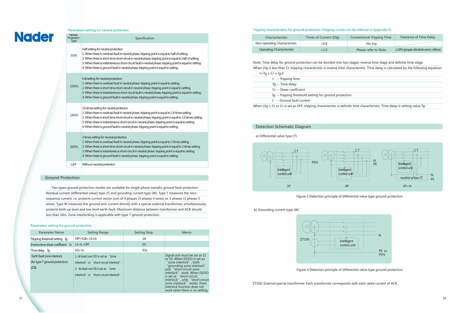
Tripping characteristics for ground protection (Tripping curves can be referred in Appendix C)
Times of Current (I/Ig) Conventional Tripping Time
No trip
Please refer to Note.
<0.8
≥1.0
Note: Time delay for ground protection can be devided into two stages: inverse time stage and definite time stage.
When l/lg is less than Cr, tripping characteristic is inverse time characteristic. Time delay is calculated by the following equation:
t=Tg x Cr x Ig/I
t -- Tripping time
Tg -- Time delay
Cr -- Shear coefficient
Ig -- Tripping threshold setting for ground protection
I -- Ground fault current
When l/lg ≥ Cr or Cr is set as OFF, tripping characteristic is definite time characteristic. Time delay is setting value Tg.
Detection Schematic Diagram
Figure 3 Detection principle of differential value type ground protection
PEN
CT
3P
Intelligentcontrol unit
Intelligentcontrol unit
Intelligentcontrol unit
Intelligentcontrol unit
NPE
CT
4P
NPE
CT
3P+N
neultral phase CT
a) Differential value type (T)
b) Grounding current type (W)
Figure 4 Detection principle of differential value type ground protection
PE orPEN
ZT100N
ZT100: External special transformer. Each transformer corresponds with each rated current of ACB.
Two types ground protection modes are available for single-phase metallic ground fault protection:
Residual current (differential value) type (T) and gounding current type (W). Type T measures the zero-
sequence current, i.e. protects current vector sum of 4 phases (3 phases 4 wires) or 3 phases (3 phases 3
wires). Type W measures the ground wire current directly with a special external transformer, simultaneously
protects both up level and low level earth fault. Maximum distance between transformer and ACB should
less than 10m. Zone interlocking is applicable with type T ground protection.
Chartacteristic
Non-operating Chartacteristic
Operating Chartacteristic ±10% (proper absolute errot ±40ms)
Tolerance of Time Delay

29 30
Leakage protection is applicable to residual earth-leakage caused by insulation failure of equipments. Tripping
threshold I△n (in Ampere) is not related to the rated current of ACB. A external rectangle transformer is needed
for zero-sequence sampling, which has high accuracy and sesitivity and is applicable to small current protection.
Parameters setting for leakage protection
Parameter Name
Tripping threshold setting I△n
Time delay (s) T△n
Implementation mode
0.5A~30.0A
Instantaneous, 0.06, 0.08, 0.17, 0.25, 0.33, 0.42, 0.5, 0.58, 0.67, 0.75, 0.83
Trip / OFF
Setting Range Setting Step
0.1A
Tripping characteristics for leakage protection (Tripping curves can be refered in Appendix C)
<0.8
≥1.0
No Trip
Please refer to below Table.
Times of Current (I/I△n) Conventional Tripping Time
Table 2 Time delay for leakage protection
Time delay (s)
I△n
2I△n
5I△n
10I△n
0.06 0.08 0.17 0.25 0.33 0.42 0.5 0.58 0.67 0.75 0.83 Instantaneous
Maximum break time (s)
0.36 0.5 1 1.5 2 2.5 3 3.5 4 4.5 5 0.04
0.18 0.25 0.5 0.75 1 1.25 1.5 1.75 2 2.25 2.5 0.04
0.072 0.1 0.2 0.3 0.4 0.5 0.6 0.7 0.8 0.9 1 0.04
Figure 5 Detection schematic of leakage protection
ZCT1:Rectangle leakagetransformer
N PE
ZCT1
R
ZCT1
Grounding alarm and ground protection are independent of each other and co-exist with separated parameters setting.
Operating Principle
1
2
3t
4
I
Figure 6 Operation principle of alarm
1: Operating threshold
2: Operating time delay
3: Return threshold
4: Return time delay
As illustrated by figure 6: Earthing alarm is triggered according to ture rms value of grounding current. Alarm delay starts when grounding current is larger than operating thereshold (1). Alarm is sent out after operating delay time (2), grounding alarm DO acts; Return starts when grounding current is less than return threshold (3). Alarm is cancelled after return time delay (4), grounding alarm DO returns. Return threshold value should not larger than operpting thersahold value.
Parameters setting for grounding alarm
Parameter Name Setting Range Setting Step Memo
Setting only whenimplementation mode is “alarm”.
Operating threshold
Operating time delay
Return threshold
Return time delay
Alarm DO output
Implementation mode
OFF / 0.2In ~ 1.0In
0.1s ~ 1.0s
0.2In ~1.0In
0.1s ~ 1.0s
Set one DO signal as “grounding alarm”. (It is not mandatory. If this item doen’t be set, alarm
information can be read from control unit display without node output.)
Alarm / OFF
1A
0.1s
1A
0.1s
Operating characteristics for grounding alarm
Conventional Tripping Time Tolerance of Time Delay
<0.8
≥1.0
Times of Current (I/setting)
Definite time delay=Set time delay
Return characteristics for grounding alarm
Times of Current(I/setting)
>1.0
≤0.9
Characteristic
Non-return characteristic
Return characteristic
Chartacteristic
Non-operating Chartacteristic
Operating Chartacteristic
Times of current
Intelligentcontrol unit
Chartacteristic
Non-operating Chartacteristic
Operating Chartacteristic
No trip
Definite time delay=Set time delay
No return
Conventional Return Time Tolerance of Time Delay
Leakage Protection
±10% (proper absolute errot ±40ms)
Intelligentcontrol unit
Grounding Alarm
Tolerance of Time Delay
±10% (proper absolute errot ±40ms)
±10% (proper absolute errot ±40ms)
Detection principle of leakageprotection (E type groundprotection mode)

33 34
Conventional Tripping Time Tolerance of Time Delay
Parameter Name Setting Range Setting Step Memo
No return
Leakage Alarm
Leakage alarm and leakage protection are independent of each other and co-exist with seperated parmerters setting. Operating principle, operating characteristics, returncharacteristics are the same as grounding alarm.
Parameters setting for leakage alarm
Parameter Name Setting Range Memo
Setting only whenimplementation mode is “alarm”.
Operating thresholdOperating time delayReturn thresholdReturn time delay
Alarm DO output
Implementation mode
Set one DO as “leakage alarm”(It is not mandatory. If this item doesn’t beset, alarm information can be read from control unit display without node output).Alarm / OFF
Setting Step0.1A0.1s0.1A0.1s
Current Unbalance Protection
Current unbalance protection provides protection against phase failure and current unbalance of three phases.
It implement protection according to current unbalance ratio of three phases. When implementation mode is
“alarm”, the operating principle is the same as ground protection.
Calculation of current unbalance ratio:
Figure 7 Current unbalance protection
Operating characteristics for current unbalance protection
Actual current unbalance ratio/setting
Conventional Tripping Time Tolerance of Time Delay
<0.9
≥1.1
5%~60%
0.1~40.0s
5%~ Start value
10~200s
Set one DO signal as “I unbalance alarm ”. (It is not mandatory. If this item doesn’t be
set, alarm information can be read from control unit display without node output.)
Alarm / Trip / OFF
Parameters setting for current unbalance protection
Setting only when implementation mode is“alarm”.
Protection start setting
Operating time delay
Return setting
Return time delay
Alarm DO output
Implementation mode
1%
0.1s
1%
1s
Return characteristics of current unbalance protection
>1.1
≤0.9
Demand Current Protection
Demand ture rms value of currents for each phase is calculated in a sliding time window. It implement peotection when demand value
exceeds the limit value. When the implementation mode is “alarm”, the operating principle is same as grounding alarm. The sliding time
window settings can be set in “Measuring Meter Setting” menu. Demand current protection is set separately as per different phase.
Phase A maximum demand current value
Phase B maximum demand current value
Phase C maximum demand current value
Phase N maximum demand current value (Unafffected by neutral protection settings)
Parameters setting for demand current protection of Phase A
Parameter Name Setting Range Setting Step Memo
Operating threshold
Operating time delay
Return threshold
Return time delay
Alarm DO output
Implementation mode
0.2In~1.0In
15s~1500s
0.2In~ operating threshold
15s~3000s
Set one DO signal as “demand value fault”or “ demand value fault of Phase A”.(It is not mandatory. If this item doesn’t be set, alarm information can be read from controlunit display without node output.)
Alarm / Trip / OFF
(Settings of Phase B, Phase C and Phase N are the same as settings of Pahse A)
Setting only whenimplementationmode is “alarm”.
1A
1s
1A
1s
Operating characteristics for demand current protection
Return characteristics of demand current protection(Only when implementation mode is “alarm”)
>1.1
≤0.9
Iunbal=Emax
Iavg
Iavg=
100%
Iavg: average of ture rms value of three phases current
I1+I2+I33
Emax: Max. differential value between each phase current and lavg.
<0.9
≥1.1
Times of Current (I/setting)
0.5~30.0A0.1~1.0s0.5~30.0A0.1~1.0s
Chartacteristic
Non-operating Chartacteristic
Operating Chartacteristic Definite time delay=Set time delay
No trip
Chartacteristic
Non-return Chartacteristic
Return Chartacteristic
Chartacteristic
Non-operating Chartacteristic
Operating Chartacteristic
Non-return Chartacteristic
Return Chartacteristic
No return
Definite time delay=Set time delay
Definite time delay=Set time delay
No trip
±10% (proper absolute error ±40ms)
Conventional Return Time Tolerance of Time DelayActual current unbalance rate/setting
Definite time delay=Set time delay ±10% (proper absolute error ±40ms)
±10% (proper absolute error ±40ms)
Conventional Return Time Tolerance of Time DelayTimes of Current (I/setting)Chartacteristic
±10% (proper absolute error ±40ms)

33 34
Setting Range Setting Step Memo
<0.9
≥1.1
Chartacteristic
Non-operating Chartacteristic
Operating Chartacteristic
Chartacteristic
Non-return Chartacteristic
Return Chartacteristic
Times of Voltage(Umax/ settings)
Times of Voltage(Umax/ settings)
Operating threshold
Operating time delay
Return threshold
Return time delay
Alarm DO output
Implementation mode
Control unit measures the true rms value of voltage of primary circuit. Undervoltage
protection operates when each line voltage of three phases is less than setting value.
That is Max. value of three line voltages is less than undervoltage operating threshold.
Undervoltage protection alarm returns when Max. value of three line voltages exceeds
return threshold.
Operating Principle
Alarm/tripping delay is triggered when Max. line voltage is less than operating threshold (1). Alarm or tripping
signal is sent out after after operating time delay (2), undervoltage fault DO acts; Return delay starts when Max.
line voltage exceeds return threshold (3). Alarm is cancelled and undervoltage fault DO returns after return time
delay (4).
1
2
3
t
4
U
Figure 8 Undervoltage protection operating principle
Parameters setting for undervoltage protection
100V ~ Return value
0.2~60s
Start value~1200V
0.2~60s
Set one DO signal as “undervolage fault”. (It is not mandatory. If this item doesn’t beset, alarm information can be read from control unit display without node output.)
Alarm / Trip / OFF
Setting only when executing mode is “alarm”
1V
0.1s
1V
0.1s
Operating characteristics for undervoltage protection
Alarm return characteristics for undervoltage protection(Only when implementation mode is “ alarm“)
>1.1
≤0.9
Overvoltage Protection
Control unit measures the true rms value of voltage of primary circuit. Overvoltage protection operates when each line voltage of
three phases exceeds setting value. That is Min. value of three line voltages exceeds overvoltage operating threshold. Overvoltage
protection alarm returns when Min. value of three line voltages is less than return threshold.
Operating Principle
Figure 9 Overvoltage protection operating principle
Alarm/tripping delay is triggered when Min. line voltage exceeds operating threshold (1). Alarm or tripping signal will be sent out
after operating time delay (2), overvoltage fault DO acts; When the implementation mode is Alarm, after alarm operation, return
delay starts when Min. line voltage is less than return threshold (3). Alarm is cancelled and overvoltage fault DO returns after return
time (4).
Parameters setting for overvoltage protection(Undervoltage settings must be less than overvoltage settings)
Return value~1200V
0.2s~60s
100V~ Start value
0.2s~60s
1V
0.1s
1V
0.1s
<0.9
≥1.1
Operating characteristics for overvoltage protection
>1.1
≤0.9
Return characteristic of over voltage protecting alarm
1: Operating threshold
2: Operating time delay
3: Return threshold
4: Return time delay
Parameter NameOperating threshold
Operating time delay
Return threshold
Return time delay
Alarm DO output
Implementation mode
Parameter Name
Definite time delay=Set time delay
No trip
Definite time delay=Set time delay
No return
Definite time delay= Set time delay
No return
1
2
3t
4
U
1:Operating threshold
2:Operating time delay
3:Return threshold
4:Return time delay
Set one DO signal as “overvolage fault”. (It is not mandatory. If this item doesn’t be
set, alarm information can be read from control unit display without node output.)
Alarm / Trip / OFF
Setting Range Setting Step Memo
Conventional Tripping Time Tolerance of Time Delay
Definite time delay= Set time delay
No trip
Chartacteristic
Non-operating Chartacteristic
Operating Chartacteristic
Chartacteristic
Nonoperating Chartacteristic
Return Chartacteristic
Times of Voltage(Umin/ settings)
Times of Voltage(Umax/ settings)
Undervoltage Protection
±10% (proper absolute error ±40ms)
Conventional Tripping Time Tolerance of Time Delay
±10% (proper absolute error ±40ms)
Conventional Return Time Tolerance of Time Delay
±10% (proper absolute error ±40ms)
Setting only when executing mode is “alarm”
(Only when implementation mode is “ alarm“)
±10% (proper absolute error ±40ms)
Conventional Return Time Tolerance of Time Delay

35 36
Memo
<0.9
≥1.1
Actual voltage unbalance ratio/ setting
Actual voltage unbalance ratio/setting
Parameters setting for voltage unbalance protection
100V~Return value
0.2s~60s
Start value~1200V
0.2s~60s
Setting Step
1V
0.1s
1V
0.1s
Operating characteristics for voltage unbalance protection
Alarm return characteristics for voltage unbalance protection (Only when implementation mode is “alarm”)
>1.1
≤0.9
Voltage Unbalance Protection
Voltage unbalance protection provides protection against unbalance of three line voltages. Its
operating priciple is the same as that of overvoltage protection.
Calculation of voltage unbalance ratio:
Uavg: Average of ture rms values of three phases voltage
Emax: Max. differential value between each phase line voltage and Uavg.
Figure 10 Voltage unbalance protection
Under/Over Frequency Protection
Control unit detects frequency of system voltage, may implement protection against over frequency or under frequency. Theoperating principle of under/over frequency protection is the same as that of undervoltage/overvoltage --protection.
Parameters setting for under frequency protection
(Under frequency setting must be less than over frequency setting)
45.0Hz~Return value
0.2s~5.0s
Start value~65Hz
0.2s~36.0s
0.5Hz
0.1s
0.5Hz
0.1s
0.5Hz
0.1s
0.5Hz
0.1s
Return value~65.0Hz
0.2s~5.0s
45.0Hz~Start value
0.2s~36.0s
Reverse Power Protection
Control unit measures the sum of three phase active power. It implement protection when power flow is reverse to power direction setting and power value is larger than operating setting. Power direction and power leading-in direction can be set in“Measuring Meter Setting”menu. Settings must be consistant with real application. The operating principle is the same as thatof overvoltage protection.
Parameters setting for reverse power protection
5kW~500kW
0.2s~20s
5 kW~ Start value
1.0s~360s
1kW
0.1s
1kW
0.1s
Uunbal =Emax
100%Uavg
Uavg =3
U12+U23+U31
Parameter Name
Operating threshold
Operating time delay
Return threshold
Return time delay
Alarm DO output
Implementation mode
Parameter Name
Operating threshold
Operating time delay
Return threshold
Return time delay
Alarm DO output
Implementation mode
Parameter Name
Operating threshold
Operating time delay
Return threshold
Return time delay
Alarm DO output
Implementation mode
Parameter Name
Operating threshold
Operating time delay
Return threshold
Return time
Alarm DO output
Implementation mode
Setting Range
MemoSetting StepSetting Range
MemoSetting StepSetting Range
MemoSetting StepSetting Range
Setting only when implementation
mode is“alarm”
Setting only when implementation
mode is“alarm”.
Setting only when implementation
mode is“alarm”.
Setting only when implementation
mode is“alarm”.
Set one DO signal as “U unbalance alarm ”. (It is not mandatory. If this item doesn’t be
set, alarm information can be read from control unit display without node output.)
Alarm / Trip / OFF
Conventional Tripping Time Tolerance of Time DelayChartacteristic
Non-operating Chartacteristic
Operating Chartacteristic
Chartacteristic
Non-return Chartacteristic
Return Chartacteristic
±10% (proper ablesolute error ±40ms)
±10% (proper ablesolute error ±40ms)
Definite time delay=Set time delay
No trip
Definite time delay= Set time delay
No return
Set one DO signal as “Under frequency fault”. (It is not mandatory. If this item doesn’t be set,
alarm information can be read from control unit display without node output.)
Alarm / Trip / OFF
Set one DO signal as “Over frequency fault”. (It is not mandatory. If this item doesn’t be set,
alarm information can be read from control unit display without node output.)
Alarm / Trip / OFF
Set one DO signal as “Power fault ”. (It is not mandatory. If this item doesn’t be set,
alarm information can be read from control unit display without node output.)
Alarm / Trip / OFF
Conventional Return Time Tolerance of Time Delay
<0.9
≥1.1
Operating characteristics for reverse power protection
Reverse Power Value / Setting Committed tripping time Tolerance of Time DelayChartacteristic
Non-operating Chartacteristic
Operating Chartacteristic Definite time delay= Set time delay
No trip
±10% (proper ablesolute error ±40ms)
Parameters setting for over frequency protection

37 38
Reverse power value/ setting Conventional Return Time
>1.1
≤0.9 Definite time delay = Set time delay
Alarm rerurn characteristics for reverse power protection (Only when implementation mode is “alarm”)
Phase Sequence Protection
Phase sequence detection gets from voltage of primary circuit. When phase sequence detected is the same as
setting direction of start value, the protection operates. Operating characteristic is instantaneous. This function
automatically quit when one or more phases don’t exist.
Parameter sertting of phase sequence protection
Setting Range MemoParmeter Name
Operating phase sequence
Alarm DO output
Implementation mode
Δ φ : A, B, C / Δ φ :A, C, B
Set one DO singral as “phase sequence fault”. (It is not mandatory. If this itemdoesn’t be set, alarm information can be read from control unit display without node output.)
Alarm / Trip / OFF
Load Monitoring
Load monitoring is for either pre-alarm or the control of branch circuit load. It can operate based on power or current. Two operating types are available:Type 1: Control unit controls loads in two branch circuits. When operating parameter exceeds setting value, corresponding load monitoring DO acts after time delay (Corresponding DO functions should be set). Control unit controls to break two branch circuits to guarantee power supply of main system.Type 2: Normally for the control loads in the same branch circuit. When operating parameter exceeds setting value, “Load monitor 1” DO acts after time delay to break the loads in branch circuit (operating form can be impulse type or level type). If operating parameter is less than return threshold after break-ing, “load monitor 1” DO and “load monitor 2” DO return and make loads which already break after setting time delay (impulse type or level type). System power supply is restored.
Type 1
Figure 11 Operating characteristic of load monitoring on current
Current as operating parameter. Inverse time operating characteristic is the same as that of overload protection. The ratecurve and operating value should be set independently. In type2, time delay of load return is definite time.Note: For type 2, start value L1 must not less than return value L2.
Type 2
Protection curve
of long-time delay
Protection
curve of long
-time delay
Operating principle of load monitoring on current
Operating principle of loadmonitoring on active power
Type 1
Figure 12 Operating characteristic of load monitor on active power
Active power as operating parameter. Unload and return time delay are definite time.Note: For type 2, start value P1 must not less than return value P2.
Type 2
Parmeters setting for load monitoring
Parameter Name Setting Range Setting Step Merno
Alarm DO output
Load monitoring Type
1. Current type 1
2. Current type 2
3. Power type 1
4. Power type 2
5. OFF
Current type 1/2
Power type 1/2
Current type 1/2
Power type 1/2
Current type 1
Current type 2
Power type 1
Power type 2
Current type 1
Current type 2
Power type 1/2
Tr: Tripping time for
long-time overload
protection
Ir: Tripping threshold for
long-time overload
protection
0.2Ir~1.0 Ir
200kW~10000kW
20%Tr~80%Tr
10s~3600s
0.2Ir~1.0Ir
0.2Ir~Unload I
200kW~10000kW
100~Unload I
20%tr~80%Tr
10s~600s
10s~3600s
1A (Frame I), 2A (Frame II, frame III)
1kW
1%
1s
1A (Frame I)
2A (Frame II, Frame III)
1kW
1kW
1%
1s
1s
Chartacteristic
Non-return Chartacteristic
Return Chartacteristic
No return
Tolerance of Time Delay
±10% (proper absolute error ±40ms)
Operating threshold of unload I
Operating time delay of unload I
Operating thresholdof unload II
Operating time delay of unload II
One DO signal will be set as “load monitor 1”,the other one will be set as “load monitor 2”.

39 40
Demand Value Measurement
Instantaneous Value Measurement
a)Current 1) Measur ing mode Measure rms va lue of instantaneous current , including I1 , I2 , I3 , In , ground fault current lg and leakage current IΔn. Automatically trace frequency change. Applicable to 50Hz/60Hz power grid. 2) Measurement range Measurement ranges of I1, I2, I3 and In are larger than 25 times of ACB’s rated current In. Measurement ranges of grounding current and leakage current are less than 10 times of rated current. 3) Measurement accuracy Below 2.0In, accuracy is to within ±1.5%; Accuracy is to within ±5% when current exceeds 2.0In. 4) Display in histogram Control unit displays current of phase A , B, C and neutral phase (according to system mode selection) in histogram, and also indicates percentage of each phase currents relative to overload current setting or relative to rated current when overload current hasn’t been set.b)Current unbalance ratio Iunbal This function calculates the unbalance percentage within three phase currents.
Iavg: Average of rms value of three phase currentsEmax: Max. differential value between each phase current and Iavg .
c)Voltage 1) Measuring mode Measure ture rms value, automatic trace frequency change. Applicable to 50Hz/60Hz power grid. 2)Measurement range Line voltage (phase-phase voltage): 0~1200V; Phase voltage (phase-neutral voltage): 0~600V. 3)Measurement accuracy: ±0.5%d) Phase sequence Indicate phase sequence. When there is no voltage functions, there is no phase sequence detection.e) Frequency 1) Measurement range 40Hz~65Hz 2) Error: ±0.05 Hz Note: frequency signal comes from voltage of phase Af ) Voltage unbalance ratio Uunbal This function calculates the unbalance percentages within three lines voltages.
Uavg: Average of rms value of three line voltagesE max: Max. differential value between each line voltage and Uavg.
Figure 13 Current unbalance Figure 14 Voltage unbalance
g) Power 1) Measuring mode Ture active power, ture reactive power. 2) Measurement content Active power, reactive power and apparent power of the total system; Active power, reactive power and apparent power of each phase (It is not applicable in the system of three-phase and three-line.) 3)Measurement range Active power: -32768kW ~ +32767kW Reactive power: -32768kar~+32767kar Apparent power: 0kVA~65535kVA Tolerance: ±2.5%。h)Power factor 1)Measurement content Power factor of the total system; Power factor of each phase (It is not applicable in the system of three- phase and three-line.) 2) Measurement range Range: -1.00~+1.00; Tolerance: ±0.02.i) Energy 1) Measurement content Input active energy (EPin), input reactive energy (EQin), output active energy (EPout), output reactive energy (EQout), total active energy (EP), total reactive energy (EQ); total apparent energy (ES). 2) Measurement range Active: 0~4294967295kWh; Reactive: 0~4294967295kvarh; Apparent: 0~4294967295 kVAh. 3) Measurement accuracy: ±2.5%。Note: 1) “Feeding type” in “Measuring Meter Setting” menu should be selected as “top feeding” or “bottom feeding”according to the real application status of the active power sign, reactive power sign and energy input and output. 2)Total energy value is “Total Absolute Value”, which stands for the sum of energy input value and energy output value:
a) Demand current measurement
1) Measurement content
Measure demand current value, including Ia, Ib, Ic and In.
Time parameter of demand current measurement can be set.
2)Measuring mode
Differential slide type. Time window slide range: 5~60 minutes.
3)Measurement range
Same as the current instantaneous value measurement.
4)Measurement accuracy
Below 2.0In, accuracy is to within ±1.5%; Accuracy is to within
±5% when current exceeds 2.0In.
b) Demand power measurement
1) Measurement content
Measure demand active power value P, demand reactive
power value Q and demand apparent power value S.
2) Measuring mode
Differential slide type. Time window slide range: 5~60
minutes.
3) Measurement range
Same as the power instantaneous value measurement.
4)Measurement accuracy:
±2.5%.
Iavg= I1+I2+I33
IavgIunbal=
Emax100%
U12+U23+U31
3
UavgUunbal=
Emax100%
Uavg=
EP=∑EPin+∑EPout EQ=∑EQin+∑EQout
Iavg
IU
UavgEmax Emax
I1 U12 U23 U31I2 I3
Measurement Function

41 42
About harmonic
Harmonic is the most common problem in modem electrical equipments. The waveform of current or voltage will not be absolute sine curve but be distorted when there is a harmonic. Distorted waveform of current or voltage will affect energy distribution. Then quality of the power supply can not be optimization. Harmonic is caused by non-linear loads. The waveform of current flowing through this kind of load is not consistent with the waveform of the voltage. Typical non-linear load usually is used in power electronic equipment with steady increasing preportion in electronic product consumer market. Common non-linear loads are just like welding machine, arc furnace, rectifier, speed regulator of asynchronous or D.C. motor, computer, copy machine, fax machine, televi-sion, microwave oven, neon light, UPS, and so on. Non-linear phenomena could also be caused by convertor or other equipments.a) Definition of harmonic A signal consists of the following factors: 1) Signal of original sine curve under fundamental frequency 2) Signals of other sine curve (harmonic) whose frequency is integer multiple of fundamen-tal frequency 3) DC component (In some cases), any one of these signals can be expressed as following formula:
In this formula: Y0 stands for DC component (Usually consider as 0); Yn stands for rms value of n-th harmonic; ω stands for the angular frequency of fundamental wave; φ stands for the phase shift of harmonic when t=0. Harmonic order n stands for n-th harmonic which is a sine curve signal whose frequency is n times of fundamental frequency.For example, usually there are following characteristics with waveform of current and voltage: Fundamental frequency is 50Hz; Frequency of second harmonic is 100Hz; Frequency of third harmonic is 150Hz; …… Distorted waveform is made by superimposing multi-harmonic on the fundamental wave.b) Affections of harmonic 1) Increase the current in the system, cause overload; 2) Excessive losses of equipments, cause aging in advance; 3) Affect communications network ; 4) Normal working of the loads will be affected by voltage harmonic.
Figure 15 Waveform of harmonic
Fundamental wave
Thirdharmonic
Fifthharmonic
Seventhharmonic
Ninthharmonic
Table 3 Acceptable harmonic level
Note: Harmonic content of n- th harmonic i s the percentage of rms va lue of fundamenta l . Th i s percentage w i l l beshown in the d i sp lay of cont ro l un i t . The harmonics wh ich we ca re a re : 1)Low f requence odd harmonic ; 2)Main ly th i rd harmonic , f i f th harmonic , seventh harmonic , e leventh harmonic and th i r teenth harmonic .
Odd harmonic (no multiples of 3) Odd harmonic (multiples of 3) Even harmonic
5
7
11
13
17
19
23
25
3
9
15
21
>21
2
4
6
8
10
12
>12
LV
6
5
3.5
3
2
1.5
1.5
1.5
LV
5
1.5
0.3
0.2
0.2
MV
6
5
3.5
3
2
1.5
1
1
MV
2.5
1.5
0.3
0.2
0.2
EHV
2
2
1.5
1.5
1
1
0.7
0.7
EHV
1.5
1
0.3
0.2
0.2
LV
2
1
0.5
0.5
0.5
0.2
0.2
MV
1.5
1
0.5
0.2
0.2
0.2
0.2
EHV
1.5
1
0.5
0.2
0.2
0.2
0.2
c)Acceptable harmonic level; The standards and regula-tions regarding harmonics interference: 1)Compatibil ity standards for public establishments: Low voltage: IEC6000-2-2; Medium voltage: IEC6000-2-41. 2)Electrical magnetic compatibil ity (EMC) standards: Loads of which the current is less than 16A: IEC6000--3-2. Loads of which the current is more than 16A: IEC6000--3-4. 3)Usage recommendation for the equipments Some international date have been recommended to estimate the typical harmonic value of the distribution system. A harmonic level table is in the following table. The date listed in this table should not be exceeded when application. The voltage harmonic arranged by the sequence of even number and odd number in: Low voltage (LV) system Medium voltage (MV) system Extra-high voltage (EHV) system
a) Purpose of harmonic measurement 1)Used as precautions by accessing system’s information and detecting wander ; 2)Used as corrective actions by diagnosing the disturbing or detecting the validity of a scheme.b) Fundamental measurement Including: Current-------------Ia, Ib, Ic and In; Voltage-------------Uab, Ubc, Uca and Uan、Ubn、Ucnc) Total harmonic distortion THD and thd: Current: THD, total harmonic distortion relative to fundamental, is the ratio of square root of the sum of the squares of the currents of second and above times harmonic to fundamental current. thd, total harmonic distortion of harmonic to rms value of current, is the ratio of square root of the sum of the squares of the currents of second and above times harmonic to rms value of current. It is normal when thd is less than 10%. There is obvious harmonic interference which may cause temperature rising when this value is between 10% to 50% and cables should be increased. There is grave harmonic interference when this value is more than 50%. Normal working may be affected. It needs to make in-depth analysis on the equipments. Voltage: THD, total harmonic distortion relative to fundamental, is the ratio of square root of the sum of the squares of the voltages of second and above times harmonic to fundament voltage. thd, total harmonic distortion relative to rms value of voltage, is the ratio of square root of the sum of the squares of the voltages of second and above times harmonic to rms value of current. It is normal when thd is less than 5%. There is obvious harmonic interference which may cause temperature rising when this value is between 5% to 8% and cables should be increased. There is grave harmonic interference when thd is more than 8%. Normal working may be affected. It needs to make in-depth analysis on the equipments.d) Amplitude specturm of the thirty-one previous odd harmonies. Control unit can show FFT amplitude of harmonics from third one to thirty-frist one. The amplitudes of harmonics of different frequency will be shown in histogram by control unit to form harmonic spectum analy-sis.
Harmonic Measurement Content
y(t)=Yo+∑Yn╳sin(nωt-φn)
Ipeak
Irms
I1
I3
I5
I7
I9
Sequence n Sequence n Sequence nHarmonic Measurement

43 44
a) System type
3Φ3W3CT: System type: three phases and three lines; Number of poles of ACB: 3 poles.
3Φ4W3CT: System type:three phases and four lines; Number of poles of ACB: 3 poles.
3Φ4W4CT: System type:three phases and four lines; Number of poles of ACB: 4 poles or 3
poles With external N phase (3P+N).
b) Feeding type
Top feeding: Feeding from the top of ACB; Bottom fedding: Feeding from the bottom of ACB.
c) Power direction
P+: Power receiving, consuming power ; P-: Power generation, output power.
Waveform and Waveform Capture
Measuring Meter Setting
Historical Peak
a) Historical current peaks Record content: Maximum value of I1, I2, I3, In, grounding current lg and earth leakage current IΔn since operation. The value can be cleared manually.b) Historical demand value peaks Record content:Maximum value of Ia, Ib, Ic, In, P, Q and S since operation. The value can be cleared manually.
Contact Equivalent
Control unit will calculate the wearing status of the contact according to the mechanical endurance of the contact, breaking current and other parameters and display it. The contact endurance is 0 when control unit leaving factory, which stands for without wearing. When the value is up to 100%, alarm signal should be sent to remind user taking maintenance measures in time. After replacing contact, contact endurance value can return to initial value by pressing buttons. But the total endurance is sti l l saved as total consuming contact endurance.
Record the total operation times of ACB. The value can be cleared manually.
Operation Times
Fault Recording Function
a) The last eight trips are recorded and can be displayed at any time.b) Recorded parameters for every trip: 1) Reason of trip 2) Trip threshold 3) Delay time 4) Current or voltage value (blank for some fault type, such as MCR trip, under voltage trip, etc) 5) Fault time (year/month/day/hour/minute/second)
Alarm Historical Record Position Change Record
a) The last eight alarms are recorded and displayed at any time
b) Recorded parameters for every alarms:
1) Reason of alarm
2) Alarm threshould
3) Alarm time (year/month/day/hour/minute/second)
a) The last eight position changes can be recorded and displayed at any time
b) Recorded parameters for every potion change:
1) Type of position change (opening/closing/tripping)
2) Reason of position change (local/remote control, fault/test tripping)
3) Time of position change (year/month/day/hour/minute/second)
Control unit will display fault information and send alarm signal in case of EEPROM error, lost of parametersettings, AD sampling error, RAM error or ROM error.
Self-test Function
Communication
3H type control unit can execute remote control, remote-adjust, remote-meter and remote-information through communication interface according to defined protocol. Output of communication interface has photoelectric isolation thus enables the equipment to operate under strong electric interference environ-ment. All communication protocols are integrated and external protocol interpretation are not required. Communication parameters setting can be referred in Table 4. Details regarding communication can be referred in <3H Communication Protocol>.
Table 4 Communication parameters setting
Protocol
Address
Baud rate (bit/s)
Modbus
0~255
9.6k, 19.2k, 38.4k, 115.2k
Profibus-DP
3~126
Adaptive (9.6K~12M)
DeviceNet
0~63
125k, 250k, 500k
DI/DO function
DI input function: Control unit can provide 1 to 2 groups of programmable DI when signal unit is set as S2 or S3.Table 5 DI parameters setting
Function setting
DI method
Alarm, Tripping, Zone Interlock, Common, Grounding Interlock, Short-circuit Interlock
Normal Open Normal Close
Control unit can capture the waveforms of current and voltage by using the digital sam-pling technology which is similar with the technology of oscil lograph. Waveform capture is the method to detect the weak parts of system and equipments. Harmonic level, harmonic direction and amplitude can be ascertained from the information shown by waveform capture.a) Users can view the following waveforms manually: Four currents: Ia, Ib, Ic and In; Three phase voltages: Uan, Ubn, Ucn.b) Records are in a circular wave.
Maintenance Function
Control unit can provide 4 groups of programmable input and output unit. User can select upon demand. S1: 4DO; S2: 3DO+1DI; S3: 2DO+2DI

45 46
Table 6 DO parameters setting
Function Setting
Implementation mode
Impulse time
Normal open level
No 1s~360s, step 1s
Normal close level Normal open impulse Normal close impulse
Please refer to Table 7
Common
Load monitor 2
Grounding/leakage fault
Overvoltage fault
Inverse power fault
MCR/HSISC fault
Phase C demand value fault
Alarm
Ooverload pre-alarm
Grounding alarm
Voltage unbalance fault
Zone interlock
Grounding interlockNeutral phase demand value fault
Fault tripping
Overload fault
Current unbalance fault
Under frequency fault
Closing
Short-circult interlockDemand valuethreshold-crossing
Self test alarm
Short-time delay fault
Neutral phase fault
Over frequency fault
Opening
PhaeseA demand value fault
Load monitor 1
Instantaneous fault
Undervoltage fault
Demand value fault
Phase sequence fault
Phase B demand value fault
Note: “Commonl”here means DI and DO are not used in control unit itself, while can be used by upper level computer in communication network.
I/O Status
Current I/O status can be checked:
DO: “1” stands for closing status of output relay;“0”stands for opening status of output relay.
DI: “1” stands for action; “0” stands for re-setting. (When implementation mode is set as DI)
Zone Selective Interlock (ZSI)
Figure 16 Zone selective interlock
1
2 3 4
D0
D1
D0
D1
D0
D1
D0
D1
AC 220VDC 110V
Zone selective interlock includes short-circuit interlock and grounding interlock . Among two or more levels associated ACBs in one power system: a) If there is short-circuit or grounding fault in outgoing side (such as position ②) of lower level ACB (2# - 4#), lower level ACB trips instantaneously and sends out zone interlock tripping signal to upper level ACB. Upper level ACB (1# ) starts time delay according to short-circuit or ground protection settings after receiving zone interlock signal. If fault current disappears during time delay process, then protection returns and upper level ACB will not trip. If fault current lasts after time delay process, then upper level ACB will trip according to short-circuit or ground protection settings. b) If short-circuit or ground fault happens at the position between upper level ACB (1#) and lower level ACB (2# -4# ), such as position ① , upper level ACB will not receive zone interlock signal thus trip instantaneously to opens fault circuit immediately.Parameter setting: 1) At least one DI of upper level ACB is set as zone interlock test; 2) At least one DO of lower level ACB is set as zone interlock signal output.
DO output function: Trip unit provides 2 to 4 groups of independent signal output.
Table 7 DO functions setting

47 48
Test & Lock
a) Test tripping operation Test type: three-segment protection test, ground/leakage fault test, mechanism operation time test.Three-segment protection test: Input simulated fault current to test the protection status of control unit when there is overload, short-circuit or insrantaneous fault.Ground/leakage fault test: Input simulated ground/leakage fault current to test the protec-tion status of control unit when there is ground/leakage fault current. Mechanism operation time test: It is for operation characteristics setting check . Force flux transfer trip to operate to test the proper tripping mechanical time of control unit.
Table 8 Test parameters setting
Test type
Test parameters
Test control
Three-segment Protection
0A~65.5kA (Note 1)
Start + Stop
Ground/leakage Fault
0A~65.5kA (Note 2)
Operation Time
--
Note: 0~10kA , step 1A ; 2. For ground fault test: same as Note 1; 10kA~65.5kA , step 0.1kA. For leakage fault test: 0~100A, step 0.01A 100A~655A, step 1A.
b)Remote locking
Lock: In “Lock” status, control unit does not respond to remote control command from upper level computer.
Unlock: in “Unlock” status, control unit responds to remote opening, remote closing, remote re-setting, etc
commands from upper level computer.
c)Parameters locking
Lock: In “Lock” status, users can not modify parameters.
Unlock: In “Unlock” status, users can modify parameters.
Factory Settings of Control Unit
Instantaneous short-circuitprotection
Short-time short-circuitprotection
IR
IS
Ig 0.5× In (In≤ 2000A)
1× In
1× In
Tg 0.1s (Definite time)
Ic1Ic2Ii
OFF
ISd
1×In
Ground protection
Load monitoring
60s
6×In
8×In
0.2s10×In
TSd
C3
TR
Note: 1. User can set upon demand, but can not cross setting, i.e. parameter setting must conform to Ii≥lsd≥lr. 2. Please declare special requirement while ordering.
I t2
Operation Voltage Selection of Control Unit
Type
Control Trip (Ue)
AC
Rated voltage (V)
DC
110, 220220(230), 380(400)
Accessory of Control UnitST201 Relay Module
Signal unit from control unit normally is used for fault alarm, indication, etc. It need to be transform by ST201 Relay Module when the signal unit is used to control making or breaking of ACB or the capacity of load is relative higher. Contact capacity of ST201 is: AC250V, 10A; DC28V, 10A. The outline and installation dimensions are the same as those of ST power module (IV).
ST Power Module (IV)
ST power module can supply the 24V DC power of which the power is no less than 9.6W. It can output four groups terminals.
Input can be DC or AC. It also can be used as power supply for ST201 relay module. This product adopts 35mm DIN rail
installation or directly fixed installation. The dimension of outline and installation is as following:
Figure 20 ST 201 Relay Module Figure 21ST-IV Power Module
Figure 22 Installation construction ofST201, ST power module (IV)
Long-time overload protection
Tripping curve type
Thermal memory function
Curve setting of long-timeoverload protection

49 50
ZT100 Ground Transformer
The external special transformer is used when ground protection mode is ground current type (W).
The installation dimensions are as following:
N-phase External Transformer
The external N-phase transformer or ground current transformer is used when choosing 3P+N differential
value type ground protection. The installation dimensions are as following:
1 - Wiring board 2 - Bus 3 - Fixed plate 4 - Transformer
Mounting hole M8 screw 6- 8
Secondary output terminalM3.5 screw
ZCT1 Leakage Transformer
External special rectangle transformer when ground protection type is E type grounding
mode. The installation dimensions are as following. User can consult with the manufac-
turer regarding special requirements.

Mechanical AccessoryDoorframe
Installed on the door of cubicle to seal ACB and make the protection degree of ACB
reach IP40.
Closing Release
Under energy storing status, it can close the ACB if it is electrified.
Rated control voltage (V) Us
Trip voltage
Instantaneous current (A)
Closing time (ms)
AC400 AC230 DC220DC110
(0.85-1.1)Us
1.2 1
≤60
Motor for Electrical Charging
ACB is with motor electrical charging and automatic re-charging function. (ACB can be energized manually)
Rated control voltage (V) Us
Trip voltage
Power consumption
Charging time (s)
AC400 AC230 DC220
(0.85-1.1)Us
75VA 75W5s
Positions Indication Contacts For output of ACB's position status indication.
Interphase Barriers Be installed vertically between fixed wiring plate of Drawout ACB to increase insulating strength between phase and phase of main circuit to avoid short-circuit within phases.
"Disconnected" position key lock Opening push-button can be locked in pressed down status with "Disconnected" position key lock. After selected by customers, the manufacturer will install this device.
One ACB is equipped with one key and one lock. When ACB is locked, ACB can not be closed;Two ACBs are equipped with the same locks respectively and one key. Only one of them can
be closed;Three ACBs are equipped with the same locks respectively and two keys. Only two of them can
be closed.
Auxiliary Contact
Standard auxiliary contacts is 3NO+3NC. Special type is 4NO+4NC.
Rated Operational Voltage (V) Ue
AC400
AC230
DC220 DC110
Conventional Thermal Current (A) Ith
6
Rated Control Capaity
800VA
60W
AccessoryElectrical Accessory
Undervoltage ReleaseNote: Time delayed undervoltage release is recommended in frequently occurrence areas for thunderstorm or power grid which can adjust the delayed time through the switch in undervoltage release device. The setting value of delayed time is 1s, 3s, 5s.
Rated operational voltage (V) Ue
Trip voltage
Reliable closing voltage
Reliable non-closing voltage
Power consumption (VA)
(0.35-0.7)Ue
(0.85-1.1)Ue
≤0.35Ue
15VA
AC400 AC230
Shunt ReleaseIt is used to remotely trip ACB.
Rated control voltage (V) Us
Trip voltage
Instantaneous current (A)
Closing time (ms)
AC400 AC230 DC220DC110
(0.7-1.1)Us
1.2 1
≤60
51 52

53 54
Mechanical InterlockCable interlocking between two ACBs
Connecting rods interlocking between two ACBs (Unit: mm)
N N
R≥120mm
Max. 2m
50
40180
Max
. 600
153
163
65 50166 bottom
NDW2-1600 DimensionDrawout NDW2-1600 3P
Drawout NDW2-1600 4P
Fixed NDW2-1600 3P
Rated Current (A)
200~ 630
800~1250
1600
Dimension B (mm)
5
10
15
Rated Current (A)
200~ 630
800~1250
1600
Dimension B (mm)
5
10
15
Rated Current (A)
200~ 630
800~1250
1600
Dimension B (mm)
5
10
15
357
357
180 (3P)
250(4P)
324(4P)
254 (3P)
365
4-Ø6.5
95 74
300(Connected position)
347(Disconnected position)
99.5
112
4-Ø6.5
95 74
99.5
112
335
266
247
140
65
100 87.5
199
4-Ø6.5
Fixed NDW2-1600 4P
Rated Current (A)
200~ 630
800~1250
1600
Dimension B (mm)
5
10
15
335
65
100
199
87.5
140
316
4-Ø6.5
336
52 60
N
100
N
300(Connected position)
347(Disconnected position)

Wiring of NDW2-1600 ACB
Drawout NDW2-1600 Fixed NDW2-1600
Horizontal wiring Horizontal wiring
Horizontal wiring
Vertical wiring Vertical wiring
Vertical wiring
Horizontal wiring
Vertical wiring
112
140
65
46 515146
12.5
140
65
112
4-Ø6.5
99.5
95
226
226
70
16-Ø11
12.5
16-Ø11
70 70 70 70 70
70 70 7070 70 70
99.5
100
111.5
111.5
Aperture of Cabinet Door and Installing Holes Diameter
Drawout NDW2-1600 (3P)
11- Ø4.5
7.5
7.5
43.5
1522
8
70.5
39.5
140
74
6
Bottom of ACB
135 135
231
Center of ACB
Drawout NDW2-1600 (4P)
11-Ø4.5
7.5
7.5
43.5
1522
8
70.5
39.5
140
74
6
Bottom of ACB 231
135 13535
Center of ACB Center of mounting hole
Fixed NDW2-1600 (3P)
20
39Bottom of ACB
10-Ø4.5 135 135
231
51.5
140
74
228
Center of ACB
Fixed NDW2-1600 (3P)
20
39
Bottom of ACB135
231
51.5
140
74
228
152.5 17.5
Center of ACB Center of mounting hole10-Ø4.5
2545
2545
55 56

Electrical Wiring Diagram
- +1819
PENL
Power module
171614151312
53 421
Indication of three positions of drawout ACBAuxiliary switchShuntrelease Closing
Energystoringindication
"Disconnected" positionindication
"Test" positionindication
"Connected" positionindication
Closingindication
Openingindication
Under-voltagerelease
Control unit
Fault indication
Main circuit
Control power
FU
FU
MXFQSAL
XT
TA
XT
NPE
S1
1311743 15 17 20 22 24 26
2927
3331
30
28
25232116141210865
21
SB2 SB1 SB3
9PE
32
3735
34 36
4139
38 40
4543
42 44
S2 S3 S4 S5 S6 S7
SADF DF
1#, 2#: For power input.3#, 4#, 5#: Output of fault trip contact.6#, 7#: Terminals for external transformer.8#, 9#: Wiring terminals for communication.10#, 11#: Wiring terminals for first contact output.12#, 13#: Wiring terminals for second contact output.14#, 15#: Wiring terminals for third contact output.16#, 17#: Wiring terminals for forth contact output.20#: Wiring terminals for PE-phase.21#, 22#: Wiring terminals for undervoltage release.23#, 24#: Wiring terminals for shunt release.25#, 26#: Wiring terminals for closing release.27#, 28#, 29#: Wiring terminals for motor for electrical charging.30#~45#: Wiring terminals for auxiliary contacts.
Note:1.Please connect the corresponding power voltage according to different rated operation voltage of Q, F, X, M.
2.Terminal 29# can be connected to power directly (automatic pre-energy storing). It can also be connected with NO
push-button in series and then connected to power (manual pre-energy storing).
3.Buttons and indication lamps are supplied by user.
4.When operational voltage of control unit is DC power, additional power module is needed. At the same time, terminal
1# and 2# are forbidden to be connected to AC power. DC power DC110V or DC220V is input from U1(+), U2(-). Two
output terminals of power module should be connected to 1(+), 2(-) in wiring chassis of auxiliary circuit.
5.Contact output of additional functions can be selected according to above form.
Components and signs' implication:
SB1 - Shunt button; SB2 - Emergency disconnected button; SB3 - Closing button; XT - Auxiliary wiring circuit; TA - Current transformer; S1~S7 - Indicator (supplied by user); FU - Fuse (supplied by user); Q - Undervoltage release (additional accessory); F - Shunt release; X - Closing release; TM - Motor for electrical charging; SA - Motor limit switch; DF - Auxiliary switch
Basic Operation
Energy storage operation
Energy storage by handleMove the handle up and down for several times till there is no counter-force
from the handle. That means energy has be stored. At the meantime, "Spring energy storage indicator" will indicate "Charged".
Energy storage by electrical operating mechanismAfter control circuit is electrified, the ACB will be charged by motor
operating mechanism automatically.
Open/Close operation
Open by handle
When the ACB is being charged and in disconnected status, press "I" push-button, the ACB will be closed. "Main contact position indicator" will be turned to "I" from "O" and "Spring energy storage indicator" will be turned to "Discharged" from "Charged".
Insertion of drawout ACB
1. Draw out guide rail.
2. Place the circuit breaker in the guide rail.
Notes:
a. Do not impact the terminals of auxiliary circuit.
b. The projecting supports on two sides of ACB itself should be placed into the
grooves of guide rail.
c. Guide rail can be drawn out only when "Locking device of guide rail" is pressed.
Close by handleWhen the ACB is in connected status, press "O" push-button, the ACB will
be opened. "Main contact position indicator" will be turned to "O" from "I".
Electric open/closeClose: When the ACB is being charged and in disconnected status, closing release will make the ACB close under rated
control voltage. Open: When the ACB is in connected status, shunt release will make the ACB open under rated control voltage.
57 58

3. Push the breaker itself into the cradle till hearing two “Clac”s. The breaker itself is in "Disconnected" position. "Locking device guide rail" is locked.
Note:
a. When the "Unlock button of position locking device" can not be pressed down, slightly wag the racking handle from side to side till the button can be pressed down.b. Testing ACB is forbidden when the ACB is in "Connected" position.
"Connected" positionMain and auxiliary circuits are making. Can operate the ACB manually or by motor.
"Test" positionAuxiliary circuit is making and main circuit is disconnected. Can operate the ACB manually or by motor.
"Disconnected" positionDisconnect main and auxiliary circuits. Can manually operate the ACB without affecting the operation of power grid.
When ACB is in such position, "Unlock button of position locking device" pops up. Then the ACB is completely installed. It should not to rotate the racking handle clockwise continuously.
4. Draw out racking handle.
5. Insert hexagon head of the racking handle into the working position in cradle. Press down the "Unlock button of position locking device" and rotate the racking handle clockwise at the same time. The breaker itself moves inwards. (During the moving process from "Disconnected" position to "Connected" position, the "Unlock button of position locking device" will be ejected to lock the racking handle. In such case, press down the "Unlock button of position locking device" as shown in following picture. Then the racking handle can be rotated again.)
Extract the ACB1. Draw out the racking handle and insert hexagon head of the racking handle into the working position in cradle. 2. Press down the "Unlock button of position locking device" and rotate the racking handle counterclockwise at the same time. (During the moving process from "Connected" position to "Disconnected" position, the "Unlock button of position locking device" will be ejected to lock the racking handle. In such case, press down the "Unlock button of position locking device" as shown in following picture. Then the racking handle can be rotated again. )
Note:a. When the "Unlock button of position locking device" can not be pressed down, slightly wag the racking handle from side to side till the button can be pressed down.b. Testing ACB is forbidden when the ACB is in "Connected" position.
3. Draw out the racking handle and put it into its storage place. Then extract the ACB.
"Connected" positionMain and auxiliary circuits are making. Can operate the ACB manually or by motor.
"Test" positionAuxiliary circuit is making and main circuit is disconnected. Can operate the ACB manually or by motor.
"Disconnected" positionDisconnect main and auxiliary circuits. Can manually operate the ACB without affecting the operation of power grid.
Note:Guide rail can be drawn out only when "Locking device of guide rail" is pressed.
4. Extract the ACB.
Note: Slightly lift up the ACB and translate it for short distances. Then lift up the whole ACB. Do not impact the terminals of auxiliary circuit.
5. Push the guide rail into the cradle till two "Clack" are heard. "Locking device of guide rail" will lock the guide rail.
Position Locking of Drawout ACBWhen ACB is in any position, pull tab and fit padlock. Then the ACB can be locked
in that position.
1. Pull tab.
59 60

2. Fit padlock. Then the ACB can not be adjusted to other positions.
Note: Position locking tab can be pulled only when racking handle is drawn out from
the working position.
Power Consumption (Ambient temperature: +40℃)Power consumption is the total power loss measured when ACB is under frame size current Inm.
3-pole
130
4-pole
150
Type
NDW2-1600
Power Consumption (W)
Derating Coefficient
Under the conventional thermal conditions according to IEC 60947-2/GB
14048.2.
+40℃
1Inm
+45℃
0.97Inm
+50℃
0.95Inm
+55℃
0.90Inm
+60℃
0.87InmSustained current-carrying capability Inm=1600A
Ambient temperature
Power Consumption, Derating Coefficient and Copper Bus Size
Copper Bus
Under the conventional thermal conditions according to IEC60947-2/GB14048.2 and ambient temperature up to 40℃.
Frame SizeInm(A)
1600
Number of Bus
1
1
1
2
2
Rated CurrentIn(A)
≤630
800
1000
1250
1600
Size(mm×mm)
50×5
50×10
50×10
50×10
50×10
Spec of Copper Bus
61 62
Installation Notice
For the safety of operators and electrical equipments, please do as following before ACB is put into operation:
Carefully read the Operation Munual before installing and using ACB.
ACB should be used under normal working condicitions.
Check whether the specifications of ACB meet the usage requirements before installation.
Measure the insulation resistance by megger with rated 500V. It should be no less than 10M under the conditions of
the ambient temperature of 20℃ (±5℃) and the relative humidity from 50%-70%. Otherwise it need to be dried until
the insulation resistance reach the aforementioned requirement.
Please make sure that there is no conductive foreign material falling into ACB during installation.
The conductive bus connected with ACB should be in order and without additional mechanical stress during wiring.
When installing, it is necessary to provide reliable ground protection to ACB. There should be obvious grounding sign
in grounding point. Safety distance should be strictly observed for fixed ACB.
Before energizing main circuit, it is necessary to check ACB as following steps to make sure everything is normal:
a. Carefully check whether there is any foreign material falling into ACB. Clear up foreign material if there is. ACB
should be kept clean.
b . Wire auxiliary circuit according to relative electrical diagram well. Check whether operation voltage of undervoltage
release, shunt release, closing release, motor, intelligent control unit and associated parts is consistent with actual
power voltage. Then electrify the auxiliary circuit. For drawout ACB, the breaker itself should be in “Test” position.
Then ACB can be closed when making undervoltage realse closing.
c. After motor stores energy, press closing push-button (manual operation or motor operation), ACB should be closed.
d. Press opening push-button (manual operation or motor operation), ACB should open.
e. When energy storing manually, trigger the handle in front panel up and down for seven times till sound“Clac”can
be heard. The panel will indicate “Charged”. Then after electrify undervoltage release, closing operation can be carried
out (manual operation or motor operation).
Only passing aforementioned tests, ACB can be put into operation.

63
Product Maintenance Each rotational parts should be injected lubricating oil periodically during usage.
Clear the dust periodically to keep the good insulation of ACB.
1 . Whether arc chute is in good condition?
2 . Whether contact performance is well?
3 . Whether fasteners of each linkage parts are tight?
Fault Analysis and Trouble Shooting
1
Item No. Troubles The Possible Causes The Trouble Shooting Methods
2
Tripping
3
4
5
6
7
8
64
During the process of installation, adjustment and operation, there may be misusage or
simple mechanical failure. The following methods may help you to solve some simple
operating problems. If the problem still exist, please contact with us and we will send our
technician for the repair service on site.
Check the main contact system periodically. Especially take the following steps to check
the main contact system after breaking due to short-circuit:
1. Check the tripping current value and the tripping time on the control unit.2. Analyse the load and power grid conditions.3. If there is ground fault, please find out and eliminate the ground fault.4. If there is no ground fault, please check whether the tripping threshold setting for ground protection (Ig) match the actual protection requirements. If not, please reset Ig to match the actual situation.5. Press the re-set push-button to store energy and close the ACB again.
1. If the voltage of undervoltage loop is less than 85%Ue (Rated operation voltage of undervoltage release), please find out and eliminate the fault. 2. If the voltage of undervoltage loop is no less than 85%Ue, please contact us to replace the undervoltage release.
1. Check the trippinging current value and the tripping time on the control unit.2. Analyse the load and power grid conditions.3. If there is overload fault, please find out and eliminate the overload fault.4. If there is no overload fault, please check whether the current setting for overload protection (Ir) matches the actural operation current. If not, please reset lr value to match the actual situation.5. Press the re-set push-button to store energy and close the ACB again.
1. If the voltage of undervoltage loop is less than 85%Ue (Rated operation voltage of undervoltage release), please find out and eliminate the fault. 2. If the voltage of undervoltage loop is no less than 85%Ue, please contact us to replace the undervoltage release.
1. If the voltage of motor loop is less than 85%Us (Rated opera-tion voltage of motor), please find out and eliminate the fault. 2. If the voltage of motor loop is no less than 85%Us, please contact us to replace the motor for electrical charging.3. Using the manual operation for electrical charging to make sure the ACB works.4. If there is any problem about manual energy storing, please contact us for repair.
1. Turn the drawout ACB into the “Connected” position (hearing “Clac” twice) and watch the “Connected” signal on functional position indicator on the cradle.2. Check whether the auxiliary circuit is connected.
Press the re-set push-button to store energy and close the ACB again.
Check the working status of another interlocked ACB. Only one of the interlocking ACBs can be closed.
Refer to the “Overload fault” part in Item No. 1.
1. Check the tripping current value and the tripping time on the control unit.2. Analyse the load and power grid conditions.3. If there is short-circuit fault, please find out and eliminate the short-circuit fault. And check the ACB’s condition, includ-ing main contacts, arc chute, fasteners, etc.4. If there is no short-circuit fault, please check whether the inverse time tripping threshold setting (Is) and definite time tripping threshold setting (Isd) meet the matching require-ment. If not, please reset Is and Isd values to match the actual situation. 5. Press the re-set push-button to store energy and close the ACB again.
Short-circuit fault
(The indicator for
short-circuit fault
flashes.)
Ground fault
(The indicator for
ground fault
flashes.)
Action of undervolt-
age release
Overload fault
(The indicator for
overload fault
flashes.)
The undervoltage release can not pull in.
The ACB does not store energy.
After action of the mechani-cal interlock, the ACB is locked.
Closed the overload circuit.
Refer to the “Short-circuit fault” part in Item No. 1.Closed the circuit with short-circuit current.
Refer to the “Ground fault” part in Item No.1
Refer to the “ACB does not store energy” part in Item No. 2.
Remove the padlock, open the “Disconnected” position key lock.
Check the operating mechanism. Please contact us if it is jammed.
1. Check the tripping current value and the tripping time on the control unit.2. Analyse the load and power grid conditions.3. Reset parameters.4. Press the re-set push-button to store energy and close the ACB again.
Closed the circuit with ground fault current.
Mechanical fault of ACB
Mechanical fault of ACB
There is padlock or key lock in “Disconnected” position.
The racking handle has not been drawn out.ACB is not in the “Discon-nected” position completely.
There is “Jumping over teeth” or foreign material falling into cradle and blocking the racking mechanism, or etc. faults.
ACB itself does not match the frame size of cradle.
1. Check whether the operation voltage of shunt release is no less than 70% Us.2. If Us is in the normal range, please contact us to replace the shunt release.
Shunt release does not work.
There is too large transit current when closing.
Red re-set push-button of control unit havn’t been pressed.
Contact problem of auxiliary circuit of drawout ACBACB can’t be
closed
ACB trips after
closing.
ACB can not
open.
ACB can not store energy.
The handle of drawout ACB can not insert.
Push the ACB and rail into the end.
Draw out the racking handle.
Rack the ACB to the “Disconnected” position completely.
Check and clean the foreign material. If still fail after that, please contact us.
Choose the same frame size cradle as ACB.
The ACB itself does not in the right position.
The handle has inserted but can not drive ACB.
ACB is not in “Disconnected” position completely.
ACB is not in “Connected” position completely.
Item No Troubles The Possible Causes The Trouble Shooting Methods

65
App. A Tripping Curves for Overload ProtectionAppendix: Tripping Curves
Figure A1. Comparison between different type of curves (Time delay setting: C8)
Ir (Current setting for long time delay)
Standard inverse time
10
10
1
0.1
0.011
C8
Very inverse time C8I2t Common type inverse timeExtremely inverse time (G) C8High voltage fuse compatible C8
100
1000
Trip
ping
tim
e (in
sec
onds
)
100
1000
10
10
1
0.1
1
1000
10000
100
10
10
1
0.1
1
Trip
ping
tim
e (in
sec
onds
) Tr
ippi
ng t
ime
(in s
econ
ds)
Ir (Current setting for long time delay)
Ir (Current setting for long time delay)
Figure A2. Standard inverse time
Figure A3. Very inverse time
66
Extremely inverse time (M) C8
C1

67 68
Figure A4. Extremely inverse time (For general power distribution protection) Figure A6. High voltage fuse compatible
Figure A7. I2 t
0.1
10
10
1
1
0.1
10 1
1000
100
10000
10
1
1000
100
10000
Trip
ping
tim
e (in
sec
onds
) Tr
ippi
ng t
ime
(in s
econ
ds)
Ir (Current setting for long time delay)
Ir (Current setting for long time delay)
Ir (Current setting for long time delay)
Ir (Current setting for long time delay)
10000
1000
100
10
10
1
0.1
0.01
1
Trip
ping
tim
e (in
sec
onds
) Tr
ippi
ng t
ime
(in s
econ
ds)
10000
1000
100
10
10
1
0.1
0.01
1
Figure A5. Extremely inverse time (For motor protection)

69
Figure S1. Inverse short-time delay - Standard inverse time
Figure S3. Inverse short-time delay - Extremely inverse time (for general power distribution protection)
Figure S4. Inverse short-time delay - Extremely inverse time (for motor protection)Figure S2. Inverse short-time delay - Vey inverse time
App. B Tripping Curves for Inverse Short-time Delay
100
10
10 100
1
0.1
0.01
1
Trip
ping
tim
e (i
n s
eco
nd
s)
Ir (Current setting for long time delay)
Trip
ping
tim
e (i
n s
eco
nd
s)
10 1001
1000
100
10
1
0.1
0.01
Ir (Current setting for long time delay)
Ir (Current setting for long time delay)
Ir (Current setting for long time delay)
1000
100
10
1
0.1
0.01
1 10 100
Trip
ping
tim
e (i
n s
eco
nd
s)
1000
100
10
1
0.1
0.01
1 10 100
Trip
ping
tim
e (i
n s
eco
nd
s)
70

71
Figure S5. Inverse short-time delay - High voltage fuse compatible
Figure S6. Inverse short-time delay - I2 t
1000
100
10
10 100
1
1
0.1
0.01
Trip
ping
tim
e (i
n s
eco
nd
s)
Ir (Current setting for long time delay)
Ir (Current setting for long time delay)
lg (Tripping threshold setting for ground protection)
l n (Tripping threshold setting for leakage protection)1 10 100
0.01
0.1
1
10
100
1000
Trip
ping
tim
e (i
n s
eco
nd
s)App. C Tripping Curves for Ground/Leakage Protection
Figure g1. Ground protection
Figure g2. Leakage Protection
Tg=1s
Tg=0.1s
Cr=6
Cr=1.5
10
10
1
0.1
0.01
1
Trip
ping
tim
e (i
n s
eco
nd
s)
10
10
Trip
ping
tim
e (i
n s
eco
nd
s)
1
0.1
0.01
1
72

73
Ir (Current setting for long time delay)
The above curves are based on following settings:Curve type: Very inverse time
Definite time time delay setting for short-time short-circuit protection=0.3sInverse time tripping threshold setting for short-time short-circuit protection=3×lr
Protection curve setting=C1, C8 and C16 (C1 most fast)
App. D Curve ExamplesFigure C1. Inverse time
Trip
ping
tim
e (in
sec
onds
)
10000
1000
100
10
1
1 10
C1
C16
1000.1
Figure C2. Definite time
1
0.1
1 10 100Tr
ippi
ng t
ime
(in s
econ
ds)
Ir (Current setting for long time delay)
74
The above curve is based on following settings:
Definite time time delay setting for short-time short-circuit protection=0.3sDefinite time tripping threshold setting for short-time short-circuit protection=6×lr

Breaking capacity
NDW2-1600 M 200
200NDW2-1600 H
75 76
NDW2-1600 Order Form
(Need external N-phase transformer)
(Used with ST Power module IV)
Figure C3. Inverse time and definite time
10000
1000
100
10
1
0.11 10 100
Trip
ping
tim
e (in
sec
onds
)
Ir (Current setting for long time delay)
C1
C16
The above curves are based on following settings:Curve type: Very inverse time
Definite time time delay setting for short-time short-circuit protection=0.3s
Inverse time tripping threshold setting for short-time short-circuit protection=3×lrProtection curve setting=C1, C8 and C16 (C1 most fast)
Definite time tripping threshold setting for short-time short-circuit protection=6×lr
Purchaser Quantity
Rated current
Rated current
Date
Number of poles: 3P 4P 3P+N Mounting type: Fixed Drawout
Intelligentcontrol
unit
Type Basic Functions Additional Functions Additional Accessories
2. Measurement functionFour phases current and grounding current measurementThermal capacity
1. Protection functionLoad monitoring (current mode 1)Multi-curve long-time delay protectionMulti-curve inverse short-time delay protection
Definite short-time delay protectionInstantaneous protection
Current unbalance (phase-failure) protection
Ground protection (T type as default)Grounding alarmNeutral protection
MCR & HSISC protection
3. Maintenance functionEight fault recordsEight alarm recordsEight position change recordsHistonical peak current valueContact equivalentOpeartion timesClock functionSelf-diagnoses
4. Man-machine interfaceLED display in Chinese and graphicsLED state indicatorButton operation
DUUD
HD
ModbusProfibus-DPDevice net
S1 (4DO)S2 (3DO1DI)S3 (2DO2DI)
HPDP
One of the following additional functionscan be additionally selected: (Please referto Additional Functions Table on Page 22)
One of the following zone interlockand signal output unit function can be additionally selected:
Note: Protocal can only realise “remote-adjust, remote-meter, remote-information”. If realizing“remote control, remote-adjust, remote-meter, remote-information”,following additional items are needed:Zone interlock and signal output unit functionST201 Relay moduleST Power module IV
One of the following protocolmust be chosen for 3H type:
ST Power module IV (For power supply to ST201 Relay module or DC type control unit)
N-phase external transformerZCT1Leakage transformer
ZT100 Ground transformer
ST201 Relay module(For W type grounding mode)
(For E type grounding mode)

Positions Indication Contacts
Vertical wiring
Special type 4 NO + 4 NC
77 78
NDW2-1600 Order Form
<Power module I is needed for DC power>
Note:1、If there is no special requirements, 3M type control unit will be supplied and current/time setting value of control unit will be set as default value.2、Additional fee will be needed for additional functions of control unit and additional accessories.3、Default grounding mode is T type. Default wiring method is horizontal wiring. Default auxiliary switches type is 3NO+3NC. 4、Please mark clearly other special requirements in Note column.
Intelli-gent
controlunit
Specialrequire-ment
Default value set in factory
Current, timesetting value
Current setting for long-timeoverload preotection A sTime setting
sA Time settingTripping threshold for short-timeshort-circuit preotection
A Tripping threshold for instantaneous short-circuit preotection
sATripping threshold for groundprotection Time setting(Please refer to “Factory Settings of Control Unit” on Page 48.)
T (differentialvalue type)
W (Grounding current type) (ZT100 is needed)
E (Leakage protection type) (ZCT1 is needed)Grounding mode
Requiredaccessories
Undervoltagerelease
Motor operator
Shunt release
Control unit
Closing release
Instantaneous undervoltage release
Interlock by connecting rods between 2 ACBs
Cable interlock between 2 ACBs
1 lock 1 key 2 locks 1 key 3 locks 2 keys
Time delay: 1sTime delayed undervoltage release, 3s 5s
Mechanicalinterlock
“Disconnected”position key lockAdditional
accessories
Interphase barriers
Terminal shield
Wiring type
Auxiliary switch
Note
Note

8079
上海市浦东大道1139弄6号楼 1301室
地址:
021-50930891/51920563 021-50930891
Tel:Fax :
上海市商城路297号申金大厦 1902室
地址:
021-58776026021-58776027
Tel:Fax :
郑州市农业路72号国际企业中心B座1704室
地址:
0371-63298528/636913660371-63298529/63691367
Tel:Fax :
武汉市汉口解放大道686号世贸大厦1202A
地址:
027-59501427/59501747027-59501428027-59501428-808
Tel:
Fax :
成都市东大街紫东楼段11号东方广场802
地址:
028-66587619028-84451506
Tel:Fax :
广州市海珠区新港西路235号愉景雅苑怡情居A座1101室
地址:
东莞,佛山,珠海,中山,惠州福州,厦门
联络处:
020-34201523020-34203775
Tel:Fax :
苏州市三香路353号三香广场1006室
地址:
无锡联络处:
0512-686029760512-68602976
Tel:Fax :
西安市含光路74号高层3004室
地址:
029-88462915029-88462915
Tel:Fax :
石家庄市裕华路方北新村1-2-803
地址:
0311-869746980311-86974698
Tel:Fax :
大连市沙河口区如意街46号 (天兴罗福国际中心)A-605室
地址:
0411-838987480411-83898748
Tel:Fax :
深圳市南山区艺园路115号马家龙田厦IC产业园3-009室
地址:
0755-26560518/265602990755-86241299
Tel:Fax :
北京市朝阳区北四环东路108号千鹤家园3号楼805室
地址:
唐山,包头联络处:
010-82386038/82386058010-82386078
Tel:Fax :
沈阳市沈河区奉天街346号格林自由城B座18层11号
地址:
鞍山,辽阳,锦州联络处:
024-62579902/62579903024-62579902/03-518
Tel:Fax :
哈尔滨香坊区中山路82号迷你国度大厦21层13室
地址:
0451-517132820451-86134308
Tel:Fax :
重庆市江北区建新南路11号浩博天庭7-10
地址:
023-67745931023-67865630
Tel:Fax :
长沙市五一大道湘域中央1号楼1813/14室
地址:
0731-844488760731-84445576
Tel:Fax :
济南市无影山东路38号名人时代大厦1505室
地址:
0531-859237680531-85923568
Tel:Fax :
天津市南开区卫津路18号新都大厦4号楼1门2703
地址:
022-83692122022-83692122
Tel:Fax :
南京市鼓楼区福建路31号(华富园1号)华富大厦2105室
地址:
南通,徐州联络处:
025-83479160/85158402025-83479150
Tel:Fax :
杭州市莫干山路110号华龙商务大厦412室
地址:
宁波,绍兴联络处:
青岛,淄博,威海,烟台联络处:
长春市绿园区普阳街2522号至通尚都359室内
地址:
0431-856664800431-85666480
Tel:Fax :
0571-880171200571-88017120
Tel:Fax :