PORTABLES, WHEELED UNITS, AND PRE-ENGINEERED SYSTEMS … OR CLEANGUARD OR... · Tyco Fire...
23
Hydrostatic Test Instructions PORTABLES, WHEELED UNITS, AND PRE-ENGINEERED SYSTEMS Hydrostatic Test Instructions
Transcript of PORTABLES, WHEELED UNITS, AND PRE-ENGINEERED SYSTEMS … OR CLEANGUARD OR... · Tyco Fire...

Hydrostatic Test Instructions
PORTABLES, WHEELED UNITS,AND PRE-ENGINEERED SYSTEMS
Hydrostatic Test Instructions

This manual is intended to provide persons having a practicalknowledge of testing procedures and safeguards with informationcovering the hydrostatic testing of fire extinguishers and pre-engi-neered system tanks manufactured or sold by Tyco FireProtection Products. As changes in the products or testing proce-dures occur, this information will be updated by General Bulletins.When issued, General Bulletin information always supersedesthat published here.
This manual is limited to uses herein described. For other appli-cations, contact your local distributor, Domestic District Manager,International Area Manager, or Tyco Fire Protection Products –Technical Services Department, Marinette, Wisconsin 54143-2542, USA.
Note: The converted metric values in this manual are provided fordimensional reference only and do not reflect an actual measure-ment.
ANSUL, REDLINE, and the product names listed in this manual are marks and/or registeredmarks. Unauthorized use is strictly prohibited.

TABLE OF CONTENTS
2012-DEC-20 REV. 05
TABLE OF CONTENTS
PAgE
general Information 1-6
Introduction 1Tools and Accessories 1Hydrotest Recommendations 1Table 1 – Periodic Hydrostatic Retest Requirements 2-5Reference Numbers for Code of Federal Regulations 6Manufacturing Dates 6Safety Considerations 6
Hydrostatic Testing 7-18
Hydrostatic Test for Pressure Vessels 7Table 2 – Shell Adaptors and Fittings 8-15
RED LINE, Pre-engineered Systems, 8-9and Stored PressureStationary and Wheeled Units, and 10-11Halon Wheeled UnitsSENTRY and Pre-engineered Systems 12-15
Hydrostatic Hose Test 16Table 3 – Hose Adaptors and Couplings 17Components for Hose Adaptors and Couplings 18
Hydrostatic Test Instructions
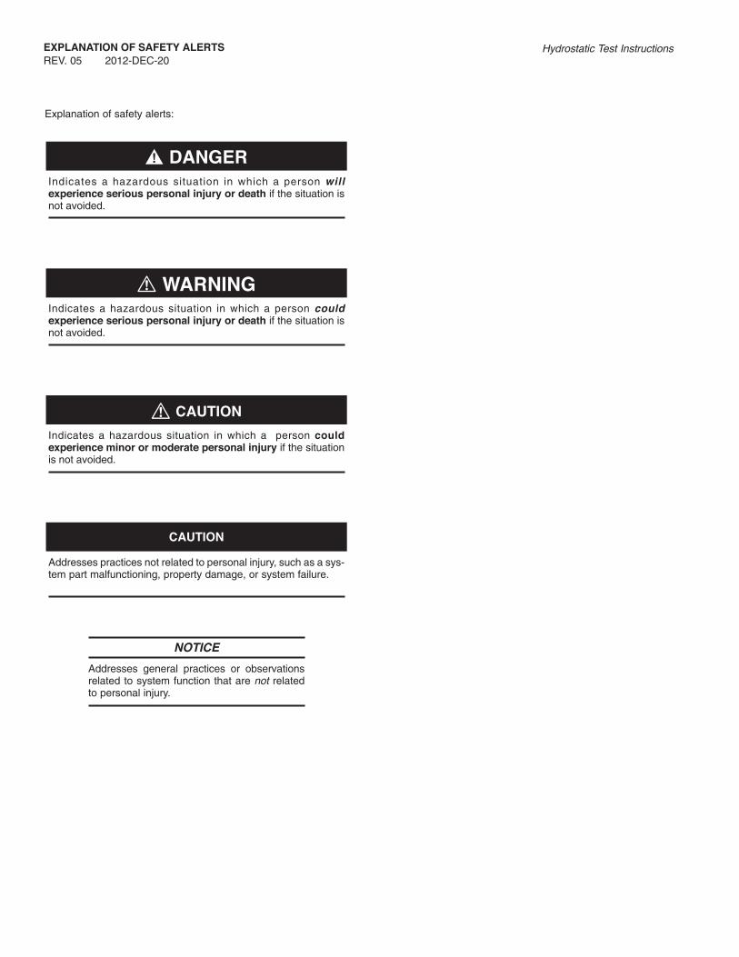
Explanation of safety alerts:
Indicates a hazardous situation in which a person willexperience serious personal injury or death if the situation isnot avoided.
Indicates a hazardous situation in which a person couldexperience serious personal injury or death if the situation isnot avoided.
Indicates a hazardous situation in which a person couldexperience minor or moderate personal injury if the situationis not avoided.
Addresses practices not related to personal injury, such as a sys-tem part malfunctioning, property damage, or system failure.
NOTICE
Addresses general practices or observationsrelated to system function that are not relatedto personal injury.
�! DANgER
! WARNINg
! CAUTION
CAUTION
EXPLANATION OF SAFETY ALERTS
REV. 05 2012-DEC-20Hydrostatic Test Instructions

gENERAL INFORMATION
2012-DEC-20 REV. 05 PAGE 1Hydrostatic Test Instructions
INTRODUCTION
Tyco Fire Protection Products (TFPP) hand portables, wheeledunits, and pre-engineered system tanks are designed, produced,and tested in accordance with standards judged by many to be themost rigid in the fire protection industry. The result is safe, effec-tive, first aid fire extinguishers.
To assure continued safe, effective operation, the pressure ves-sels must receive scheduled, periodic maintenance in strict com-pliance with procedures established by the Occupational Safetyand Health Act of 1970. Under the provisions of the Act, the ser-vicing of fire protection equipment must be conducted in accor-dance with the Standards of the National Fire ProtectionAssociation (NFPA) Pamphlets No. 10, 17, 17A, 30, 33, and 96.These standards are available on the NFPA website:www.nfpa.org.
The instructions for testing nitrogen cylinders are not in this man-ual as the test procedures require DOT certification. All ANSULnitrogen and carbon dioxide cartridges should be returned toTFPP for refilling and hydrostatic testing, unless you are a TFPPcontracted cartridge refiller.
TOOLS AND ACCESSORIES
The general use hand tools and accessories listed below are onlythose available from TFPP. For a more comprehensive guide totools, equipment, parts and lubricants used in hydrostatic testingservice operation, refer to the National Association of FireEquipment Distributors Incorporated (NAFED) “Service andRecharge Training Manual.”
Part No. Description
13133 Cartridge Receiver Wrench2609 Handle, Cart. Rec. Wrench10852 Wrench Head, Cart. Rec.6380 Cartridge Strap Wrench16511 Spanner Wrench, Fill Cap & Hydro Head4279 Nitrogen Cylinder Valve Wrench78689 Pressure Regulator Test Assembly16246 Recharge Adaptor, SENTRY Dry Chem.79730 Touch-Up Paint, Red, 9 oz. Aerosol Can79731 Touch-Up Paint, “CR” Red, 9 oz. Aerosol Can436049 Touch-Up Paint, Red – Post 2008 models,
12 – 0.6 oz. Brush-in-cap Bottles59321 Nameplate Adhesive, pint9030 Grease, Silicone 33, 5.3 oz. 699 Funnel for 10, 20, 30; 2 1/2 dia. tube1196 Funnel for Wheeled Equipment (w/screen & legs)3923 Cartridge Scale77250 Cartridge Shipping Cap15999 Inspection Seal11790 Hydrostatic Test Record Label
HYDROTEST RECOMMENDATIONS
Parts below are taken from NFPA Pamphlet No. 10, 17, 17A, 30,33, and 96. They serve as a general guide to the rules and regu-lations of hydrostatic testing as required by law.
Extinguishers and agent tanks shall be hydrostatically tested atregular intervals as required in the NFPA Standards, or more fre-quently when inspection or maintenance indicates a specific need.Such tests are usually required on extinguisher shells, cylinders,some cartridges and some hose assemblies.
If, at any time, a pressure vessel or agent tank shows evidenceof corrosion or mechanical injury, it shall be subjected to a hydro-static pressure test, or replaced. Important: air or gas should notbe used for pressure testing as failure of a shell could be violentand dangerous. When extinguisher shells, cylinders, cartridgesor hose fail a hydrostatic pressure test, they shall be destroyed.
Table 1 on pages 2-5 is designed to show what TFPP understandsto be the current legal requirements for periodic retest, indicatingboth test intervals and pressures. These requirements are shownfor the two principal authorities having jurisdiction over this type ofproduct: the National Fire Protection Association (NFPA), and theCode of Federal Regulations (DOT, MSHA, and OSHA). It isimportant to understand the jurisdiction of these two authoritiesand how it may affect the product in question. You may wish torefer directly to these principal authorities to make your own inter-pretation of the current legal requirements.
NFPA standards have no force of law in and of themselves unlessadopted by a regulatory entity that is empowered by statute toenforce regulations. However, as consensus standards developedby teams of recognized experts, they represent sound fire safetyprinciples, practices, and procedures, and we recommend thatthey be observed in the case of hydrostatic retesting. Moreover,some states and municipalities have adopted NFPA standards asa part of their fire protection codes, including those parts dealingwith the maintenance and hydrostatic retesting of extinguishers.
OSHA has safety jurisdiction over most workplaces in the U.S.,and as such its regulations have the force of federal law. OSHAhas not adopted NFPA standards for hydrotesting per se, but itsrequirements follow NFPA standards closely.
DOT’s hydrostatic retest requirements apply only to charged pres-sure vessels which are transported in commerce in the U.S. or toforeign countries. Once the product reaches its original destina-tion, DOT rules apply only when the container is reshipped in acharged condition or being re-filled.
MSHA has safety jurisdiction over mines and generally referencesthe appropriate NFPA and DOT regulations for additional guide-lines on extinguisher hydrostatic testing.
It will be noted that there are some gaps and overlapping in thelegal requirements for periodic hydrostatic retesting of some ves-sels. However, appropriate retest intervals and test pressureshave been determined for such vessels through the NFPACommittee process and/or TFPP’s own research and experience.In many cases, compliance to the NFPA standards may put you incompliance with OSHA. (Refer to the National ConsensusStandards, Appendix B, Subpart L.) A TFPP recommendation isindicated for each of the pressure vessels in Table 1, pages 2-5.
In states where the OSHA regulations differ from local regulationsor statutes, the Office of the State Fire Marshal is available forcounsel.
At intervals not exceeding those specified in Table 1, extinguish-ers shall be hydrostatically tested. For those with a designated testinterval of five years, the first hydrostatic retest may be conductedbetween the fifth and sixth years.
! WARNINg

gENERAL INFORMATION
PAGE 2 REV. 05 2012-DEC-20Hydrostatic Test Instructions
NFPA CODE OF FEDERAL
STD. RETEST TEST REF. RETESTPRESSURE VESSEL NO. PERIOD PRESSURE NO.* PERIOD
HAND PORTABLES AND WHEELED
ANSUL Stored Pressure Dry Chemical, 10 12 years Factory test pressure (not to exceed 1 12 yearsFE-36, and Halon 1211 Extinguishers 3X the normal operating pressure)(Agent Tanks)
ANSUL Stored Pressure Water and Wet 10 5 years Factory test pressure (not to exceed 1 5 yearsChemical Hand Portable Extinguishers 3X the normal operating pressure)(Agent Tanks) (See note)
ANSUL CO2 Hand Portable Extinguishers 10 5 years 5/3 service pressure as 1 5 years(aluminum and steel Agent Tanks) stamped into the cylinderD.O.T. 3A-1800, 3AA-1800, 3AL-1800and 3AA-2015
ANSUL Cartridge-Operated and 10 12 years Original factory test N/A N/AWheeled Dry Chemical Extinguishers, pressure as shown onSpill Control Applicators (Agent Tanks) the nameplate or shell
ANSUL Model 33-D AFFF 10 5 years Unspecified N/A N/AWheeled Extinguishers(Agent Tank)
ANSUL Halon 1211 Wheeled 10 Per D.O.T. Factory test pressure (not to exceed 3, 6 7 or 12 yearsExtinguishers marking 3X the normal operating pressure) (See Ref. No. 6)(D.O.T. 4BW-240 Agent Tanks) (See notes)
CO2 Cartridges for 5, 10, 20 10and 30 Models None Required 1, 4 None RequiredN2 Cartridges for 5 and 10 LowTemperature Extinguisher Models
N2 Cartridges for 20 and 30 10 Per D.O.T. or C.T.C. markings 2, 5 Per stamped markingsLow Temperature Extinguisher Models 5 or 10 years
Nitrogen Cylinders for all 10 5 or 10 years 5/3 service pressure as 2, 5 5 or 10 yearsANSUL Wheeled Extinguishers stamped into the cylinder
TABLE 1: PERIODIC HYDROSTATIC RETEST REqUIREMENTS FOR PRESSURE VESSELS IN ANSUL
— As used in this chart, service pressure and operating pressure are the same.— Dry Powder Extinguishers should be tested at the same intervals and pressures as Dry Chemical Extinguishers.
gENERAL INFORMATION
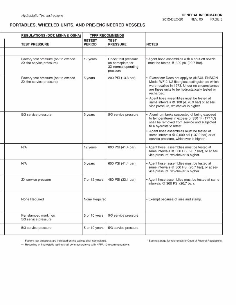
2012-DEC-20 REV. 05 PAGE 3Hydrostatic Test Instructions
REgULATIONS (DOT, MSHA & OSHA) TFPP RECOMMENDS
RETEST TESTTEST PRESSURE PERIOD PRESSURE NOTES
Factory test pressure (not to exceed 12 years Check test pressure • Agent hose assemblies with a shut-off nozzle3X the service pressure) on nameplate for must be tested @ 300 psi (20.7 bar).
3X normal operatingpressure
Factory test pressure (not to exceed 5 years 200 PSI (13.8 bar) • Exception: Does not apply to ANSUL ENSIGN2X the service pressure) Model WF-2 1/2 fiberglass extinguishers which
were recalled in 1973. Under no circumstancesare these units to be hydrostatically tested orrecharged.
• Agent hose assemblies must be tested atsame intervals @ 100 psi (6.9 bar) or at ser-vice pressure, whichever is higher.
5/3 service pressure 5 years 5/3 service pressure • Aluminum tanks suspected of being exposedto temperatures in excess of 350 °F (177 °C)shall be removed from service and subjectedto a hydrostatic retest.
• Agent hose assemblies must be tested atsame intervals @ 2,000 psi (137.9 bar) or atservice pressure, whichever is higher.
N/A 12 years 600 PSI (41.4 bar) • Agent hose assemblies must be tested atsame intervals @ 300 PSI (20.7 bar), or at ser-vice pressure, whichever is higher.
N/A 5 years 600 PSI (41.4 bar) • Agent hose assemblies must be tested atsame intervals @ 300 PSI (20.7 bar), or at ser-vice pressure, whichever is higher.
2X service pressure 7 or 12 years 480 PSI (33.1 bar) • Agent hose assemblies must be tested at sameintervals @ 300 PSI (20.7 bar).
None Required None Required • Exempt because of size and stamp.
Per stamped markings 5 or 10 years 5/3 service pressure5/3 service pressure
5/3 service pressure 5 or 10 years 5/3 service pressure
PORTABLES, WHEELED UNITS, AND PRE-ENgINEERED VESSELS
— Factory test pressures are indicated on the extinguisher nameplates. * See next page for references to Code of Federal Regulations.— Recording of hydrostatic testing shall be in accordance with NFPA-10 recommendations.

gENERAL INFORMATION
PAGE 4 REV. 05 2012-DEC-20Hydrostatic Test Instructions
NFPA CODE OF FEDERAL
STD. RETEST TEST REF. RETESTPRESSURE VESSEL NO. PERIOD PRESSURE NO.* PERIOD
PRE-ENgINEERED SYSTEMS
Pre-Engineered 17 12 years Original factory test pressure N/A N/A101/LVS Agent Tanks as shown on nameplate or shell
Industrial Dry Chemical Systems 17 12 years Factory test pressure (not to exceed 1, 3, 6 7 or 12 yearsANSUL Model SPA-50 and IND-X 2X the normal operating pressure)(D.O.T. 4BW-500 Agent Tanks)
ANSUL I-101 17 12 years Factory test pressure (not to exceed 1, 3, 6 7 or 12 years(D.O.T. 4BW-350) 2X the normal operating pressure)
ANSUL R-102 Wet Chemical Agent 17A 12 years Factory test pressure (not to exceed N/A N/ATanks (carbon steel and stainless tanks) 3X the normal operating pressure)PIRANHA
ANSUL Model H-1000 and H-101 12A 12 years Factory test pressure (not to exceed 3, 6 7 or 12 years(D.O.T. 4BW-500 Agent Tanks) 2X the normal operating pressure)
ANSUL Model H-1000 with 3A or 3AA 12/ 5 years 5/3 service pressure as 1 5 yearsD.O.T. Stamp (Agent Tanks) 12A stamped into the cylinder
Pre-engineered System Cartridges 17/ 12 years Factory test pressure 2, 5 5 or 10 years—Except LT-5, LT-10 and 101-10 17A
Pre-engineered System Cartridges 17/ None Required 1 None Required—LT-5, LT-10 and 101-10 17A Per D.O.T. 3E Stamp D.O.T. 3E Tank
TABLE 1: (Continued)
— As used in this chart, service pressure and operating pressure are the same.— Dry Powder Extinguishers should be tested at the same intervals and pressures as Dry Chemical Extinguishers.

gENERAL INFORMATION
2012-DEC-20 REV. 05 PAGE 5Hydrostatic Test Instructions
REgULATIONS (DOT, MSHA & OSHA) TFPP RECOMMENDS
RETEST TESTTEST PRESSURE PERIOD PRESSURE NOTES
N/A 12 years 600 PSI (41.4 bar) • Agent hose assemblies must be tested atsame intervals @ 300 psi (20.7 bar), or at ser-vice pressure, whichever is higher.
• At same interval test 1/4 inch actuation hose@ 1000 psi (68.9 bar).
Factory test pressure (not to exceed 7 or 12 years 1000 PSI (68.9 bar) • At same interval test 1 inch discharge hose2X the normal operating pressure) and 1/4 inch actuation hose @ 1000 psi
(68.9 bar), or at service pressure, whichever ishigher.
Factory test pressure (not to exceed 7 or 12 years 700 PSI (48.3 bar) • At same interval test 1 inch discharge hose2X the normal operating pressure) and 1/4 inch actuation hose @ 1000 psi
(68.9 bar), or at service pressure, whichever ishigher.
N/A 12 years 330 PSI (22.8 bar) • At same interval test 1/4 inch gas hose assembly @ 220 psi (15.2 bar), or at servicepressure, whichever is higher.
Factory test pressure (not to exceed 7 or 12 years 1000 PSI (68.9 bar) • At same interval test 1 inch discharge hose2X the normal operating pressure) and 1/4 inch actuation hose @ 1000 psi
(68.9 bar), or at service pressure, whichever ishigher.
5/3 service pressure 5 years 5/3 service pressure
Factory test pressure 12 years Factory test pressure
None Required • LT-5-L, LT-5-R, LT-10-L, LT-10-R, 101-10 andK-101-10 exempt because of size and stamp.
— Factory test pressures are indicated on the extinguisher nameplates. * See next page for references to Code of Federal Regulations.— Recording of hydrostatic testing shall be in accordance with NFPA-10 recommendations.

gENERAL INFORMATION
PAGE 6 REV. 05 2012-DEC-20Hydrostatic Test Instructions
REFERENCE NUMBERS FOR CODE OF FEDERALREgULATIONS CFR-49
1. Part 180.209 (e) Periodic retesting, reinspection and marking ofcylinders. Reference the table in this paragraph that specifiescylinder retest pressure and retest period. (Proposed 2006)
2. Part 180.209 (b) The periodic retest must be performed by anauthorized retester and a test by interior hydrostatic pressure ina water jacket or other apparatus suitable for determination ofthe expansion of the cylinder. (Proposed 2006)
3. Part 180.209 (6) (b) (2) Note 2 The 10 year retest period maybe extended to a 12-year period, and the 5 year retest periodmay be extended to a 7-year period after expiration of the first12-year period. (Proposed 2006)
4. Part 180.209 Table 1 (1) All cylinders not exceeding 2 inchesoutside diameter and length less than 2 feet are exempted fromhydrostatic retest. (Proposed 2006)
5. Part 180.209 (b) (i) For DOT-3A or 3AA cylinders manufacturedafter Dec. 31, 1945 and stamped with a five pointed star afterthe most recent test date the retest interval may be extended to10 years. (Proposed 2006)
6. Part 180.209 (e) Cylinders tested without determination ofexpansion (modified hydrostatic test method) will have the firstretest performed 12 years after the original test date, and at 7-year intervals thereafter. If the water jacket method is used,retest must be performed every 12 years. (Proposed 2006)
Additional References:CFR-29 Part 1910.157 (OSHA)CFR-30 (MSHA)
Part 56 Surface Metal/Non metalPart 57 Underground Metal/Non MetalPart 75 Underground CoalPart 77 Surface Coal
CFR-49 Part 173.309 Fire Extinguishers
MANUFACTURINg DATES
If the pressure vessel does not have a current hydrostatic testlabel attached to the shell with a recent test date, then the manu-facturing date is the correct date for the periodic testing of theshell. All pressure vessels with dates indicating a need for testingmust be tested to ensure the safety of the shell.
Manufacturing dates for RED LINE extinguishers are available onForm No. F-80193. Pressure vessels not listed on the form havethe date of manufacture on the nameplate; or steel stamped onthe base of the shell, under the elbow, above the elbow, on thebottom, on the collar of the shell, on the crown of the shell(wheeled dry chemical), on the bottom of the skirt (NM FE-36models), or on the hanger lug (K Class and water models).
SAFETY CONSIDERATIONS
The purpose of hydrostatic retest is to expose any weakness in apressure vessel that would make it unsafe for use. Accordingly,any pressure vessel under test must be placed in a protectivecage designed to permit visual observation of the extinguisher forevidence of distortion or leakage. When the pressure vessel is toolarge for a test cage (e.g., wheeled dry chemical extinguishers), asubstantial barrier (shield) must be placed between the pressurevessel and the service personnel.
Failure to observe these basic safety measures, and others, canresult in serious personal injury or even death.
Hydrostatic testing should only be performed by trained, qualifiedpersons with suitable testing equipment and facilities. For addi-tional guidance, refer to CFR-29, CFR-49, NFPA-10, and theCompressed Gas Association Pamphlets “C-6,” “C-6.1,” and “C-1”which cover visual inspection and hydrostatic test methods.
TFPP does not assume any liability in connection with the hydro-static testing of their pressure vessels by other than company per-sonnel. However, the following safety considerations are offeredas a guide to extinguisher service personnel.
1. Personnel performing hydrostatic testing services shouldhave practical knowledge of test equipment, testing proce-dures, and of testing safeguards as the result of “hands-on”training.
2. Service personnel should wear suitable eye protection, safetyshoes, and any other safety gear prescribed by their employ-er and/or the authority having jurisdiction.
3. A testing service company should maintain a reference libraryof procedures, standards or specifications for compressed andnon-compressed gas cylinders and cartridges, e.g.Compressed Gas Association’s Pamphlets C-1 and C-6;NFPA’s Pamphlets No. 10, 12, 12A, 17, 17A, 30, 33, and 96;OSHA’s Part 1910, Sub Part L – Fire Protection; Department ofTransportation’s Code of Federal Regulations No. 49Transportation, Parts 100-199; and where applicable theCanadian Transport Commissions counterpart regulations.
4. When disassembling components from a pressure vesselpreparatory to test, testing personnel should avoid placing anypart of their body over the pressure vessel.
5. Protective cages or barriers should not be anchored to thefloor during test operations.
6. Severely corroded or mechanically damaged pressure ves-sels should be destroyed, not subjected to pressure test tovalidate personal judgment.
7. Destruction of a pressure vessel should consist (minimal) ofdrilling a hole (1/2 in. (13 mm) diameter) in the shell throughthe UL manifest on the name plate and flattening or filing thefill opening threads to preclude further use of the vesselbeyond scrap material.
8. Service personnel should not under any circumstancesattempt to tighten a leaking connection while the pressurevessel and/or the testing apparatus is under pressure.
9. Test adaptors and fittings should be examined at periodicintervals to make certain the threads are not dangerouslynicked, cross-threaded, corroded or worn.
10. A permanent file should be maintained for each tested pres-sure vessel. This is especially true of a pressure vessel thatevidences a dent or factory made repair that was not severeenough to cause rejection under hydrostatic test.
! WARNINg
HYDROSTATIC TEST FOR PRESSURE VESSELS
The following general instructions are used with Table 2, pages8-15, which lists the specific adaptors required to test the differenttypes of extinguishers.
Always be alert for any indications of damage or inability to oper-ate the extinguisher. No manual can anticipate everything thatcould happen to an extinguisher. In the event that something notcovered in the manual is found, determine whether any potentialfor damage, effect on operation, or safety exists and repair orreplace, as necessary.
1. Carefully release any pressure from the extinguisher andremove external and internal parts from the shell. Install safe-ty shipping cap on gas cylinder or cartridge (if part of assem-bly) and place all parts in a safe location. (Refer to theOperation, Recharge, Inspection, and Maintenance Manualprovided with the extinguisher for proper procedures.)
Cartridge operated and wheeled unit extinguishers musthave gas tube removed prior to hydrostatic test (unlesswelded to the shell). Failure to remove will result in damageto the gas tube rubber.
2. Remove agent from shell and place in a labeled container.(Closed removal system recommended to limit exposure topersonnel.)
Note: Agent removed from Pre-engineered Systems shall bereplaced.
3. Remove all traces of dry chemical from the shell using dry airor nitrogen.
Restrain object being cleaned and wear proper protectiveclothing and eye protection.
4. Thoroughly examine the entire shell for signs of corrosion ormechanical damage. Refer to the “Standards for VisualInspection of Steel Compressed Gas Cylinders,” PamphletCGA C-6, from the Compressed Gas Association, Inc.
Do not perform hydrostatic test on shell in poor condition. Ifthe shell shows evidence of parent metal missing due tosevere corrosion or mechanical damage, it must bedestroyed and replaced. (See page 6, step 7.)
5. Connect the appropriate adaptors, fittings, and hose from thehydrostatic pump as indicated in Table 2, pages 8-15.
Note: If shell has a burst disk (safety release valve) replaceit with the appropriate plug.
6. Place shell in test cage or place shield between shell and allpersonnel.
7. Open vent valve and pump water into the shell. When waterstarts to flow freely from the valve, rock the shell gently torelease all air entrapped in the shell – then close vent valve.
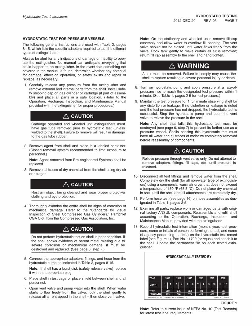
Note: On the stationary and wheeled units remove fill capassembly and allow water to overflow fill opening. The ventvalve should not be closed until water flows freely from thevalve. Rock tank gently to make certain all air is removed;return fill cap assembly to the shell and hand tighten.
All air must be removed. Failure to comply may cause theshell to rupture resulting in severe personal injury or death.
8. Turn on hydrostatic pump and apply pressure at a rate-of-pressure rise to reach the designated test pressure within 1minute. (See Table 1, pages 2-5 for test pressure.)
9. Maintain the test pressure for 1 full minute observing shell forany distortion or leakage. If no distortion or leakage is notedand the test pressure has not dropped, the hydrostatic test issuccessful. Stop the hydrostatic pump and open the ventvalve to relieve the pressure in the shell.
Note: Any shell that fails this hydrostatic test must bedestroyed (see page 6, step 7) to prevent its further use as apressure vessel. Shells passing this hydrostatic test musthave all water and all traces of moisture completely removedbefore reassembly of components.
Relieve pressure through vent valve only. Do not attempt toremove adaptors, fittings, fill caps, etc., until pressure isreleased.
10. Disconnect all test fittings and remove water from the shell.Completely dry the shell (for all non-water type of extinguish-ers) using a commercial warm air dryer that does not exceeda temperature of 150 °F (65.5 °C). Do not place dry chemicalin shell until the shell and all attachments are completely dry.
11. Perform hose test (see page 16) on hose assemblies as des-ignated in Table 1, pages 2-5.
12. Examine all parts; replace worn or damaged parts with origi-nal factory ANSUL components. Reassemble and refill shellaccording to the Operation, Recharge, Inspection, andMaintenance Manual provided with the extinguisher.
13. Record hydrostatic test information (month, year, test pres-sure, name or initials of person performing the test, and nameof agency performing the test) on the hydrostatic test recordlabel (see Figure 1), Part No. 11790 (or equal) and attach it tothe shell. Update the permanent file on each tested extin-guisher.
FIgURE 1
Note: Refer to current issue of NFPA No. 10 (Test Records)for latest test label requirements.
! CAUTION
! CAUTION
! CAUTION
! WARNINg
! CAUTION
HYDROSTATIC TESTINg
2012-DEC-20 REV. 05 PAGE 7Hydrostatic Test Instructions

HYDROSTATIC TESTINg
PAGE 8 REV. 05 2012-DEC-20Hydrostatic Test Instructions
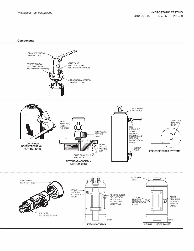
TABLE 2: SHELL ADAPTORS AND FITTINgS
ExtinguisherIdentification Part No. Description Directions
RED LINE:
5 26278 Discharge Elbow Plug Select correct plug and wrench tighten into — 3/8 in. NPT Pipe Plug discharge elbow near base of extinguisher.
(Pre 1968 shells)
27991 Test Head Assembly Insert into shell opening. Wrench tighten, using spanner wrench (Part No. 16511). Connect hydrostatic pump hose to inlet elbow.
RED LINE:
10-C, 10-E, 10-G 13133 Cartridge Receiver Wrench Use to remove cartridge receiver.20-D, 20-E, 20-G30-D, 30-E, 30-G — 3/4 x 1/4 in. Reducing Bushing Attach to cartridge receiver spud and connect
to hydrostatic pump hose.
Pre-engineered 26288 Test Head Assembly Insert into shell opening and wrench tighten.Systems:
26278 Elbow Plug Assembly (10) Select appropriate plug and install into 101-10, 101-20, 26280 Elbow Plug Assembly (20) discharge fitting on shell. (Replace burst disk)101-30 26282 Elbow Plug Assembly (30)A-101-10, A-101-20, — 3/4 in. NPT Pipe PlugA-101-30 (Pre-engineered Systems)K-101-10, K-101-20,K-101-30R-101-10, R-101-20,R-101-30PS-30, R-100LVS-5LT-A-101-50 — 1 in. NPT Pipe Plug Attach to dry chemical outlet. (Replace burst disk)
(LT-A-101-50)
LVS-15, LVS-30 — 3/4 x 1/4 in. Reducing Bushing Attach to wet chemical outlet and Vent Valve.
LT-A-101-125 — 1 1/2 x 1/4 in. Reducing Bushing Attach to dry chemical outlet and Vent Valve.
LT-A-101-250 — 1/4 in. Vent Plug Replace burst disk with pipe plug.10580 Vent Valve Connect to reducing bushing.
CAUTION: All test fittings are to be high pressure (3000 psi (207 bar)) steel construction.
HYDROSTATIC TESTINg
2012-DEC-20 REV. 05 PAGE 9Hydrostatic Test Instructions
TEST HEAD ASSEMBLYPART NO. 27991
SPANNER WRENCHPART NO. 16511
STREET ELBOW(INCLUDED WITHTEST HEAD ASSEMBLY)
VENT VALVE(INCLUDED WITHTEST HEAD ASSEMBLY)
Components
CARTRIDgERECEIVER WRENCH
PART NO. 13133
TEST HEAD ASSEMBLYPART NO. 26288
PRE-ENgINEERED SYSTEMS
GASKET,FILL CAP,PART NO.6190
QUAD RING, FILL CAP,PART NO. 6273
TESTADAPTOR,PARTNO. 26289
VENT VALVE,PART NO.10580
TEST HEADASSEMBLY
ELBOWPLUG
3/4 OR 1 IN.NPT PIPEPLUG
HIGHPRESSURESTEELREDUCINGBUSHING ANDHOSE TOHYDROSTATICPUMP
VENT VALVE,PART NO. 10580
1 X 1/4 IN.REDUCING BUSHING
LVS-15/30 TANKS
ATTACHHOSE TOHYDROSTATICPUMP
REMOVE BURSTDISK, ATTACHREDUCINGBUSHING ANDVENT VALVE
009059
LT-A-101 125/250 TANKS
ATTACHHOSE TOHYDROSTATICPUMP
1/4 IN. PIPEPLUG
ATTACHREDUCINGBUSHINGAND VENTVALVE
009060

HYDROSTATIC TESTINg
PAGE 10 REV. 05 2012-DEC-20Hydrostatic Test Instructions
TABLE 2: SHELL ADAPTORS AND FITTINgS (Continued)
ExtinguisherIdentification Part No. Description Directions
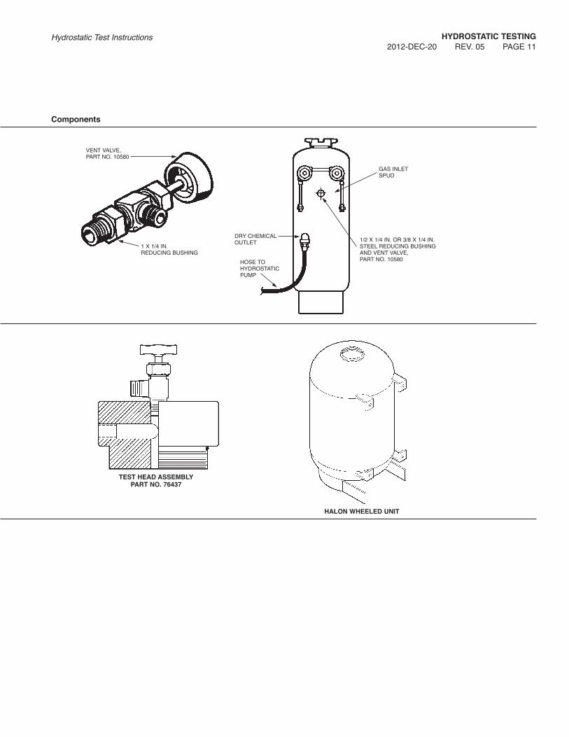
Stationary and Wheeled Units:
150-B, — 3/8 x 1/4 in. Reducing Bushing Select correct bushing and attach to150-C, — 1/2 x 1/4 in. Reducing Bushing Vent Valve.150-D
10580 Vent Valve Connect to reducing bushing (above) and install350-B, assembly into the gas inlet spud below the regulator.350-C,350-D, — 1 x 1/4 in. Reducing Bushing Attach to the dry chemical outlet and
connect to hydrostatic pump hose.
AR-33-D — 1/4 in. Pipe Plug Replace burst disk with pipe plug.(Model D units)
Halon WheeledUnits:
H-150-D 76437 Test Head Assembly Attach to shell fill opening, hand tighten.Connect to hydrostatic pump hose.
CAUTION: All test fittings are to be high pressure (3000 psi (207 bar)) steel construction.
HYDROSTATIC TESTINg
2012-DEC-20 REV. 05 PAGE 11Hydrostatic Test Instructions
VENT VALVE,PART NO. 10580
1/2 X 1/4 IN. OR 3/8 X 1/4 IN.STEEL REDUCING BUSHINGAND VENT VALVE, PART NO. 10580
GAS INLETSPUD
DRY CHEMICALOUTLET
HOSE TOHYDROSTATICPUMP
1 X 1/4 IN.REDUCING BUSHING
Components
TEST HEAD ASSEMBLYPART NO. 76437
HALON WHEELED UNIT

HYDROSTATIC TESTINg
PAGE 12 REV. 05 2012-DEC-20Hydrostatic Test Instructions
TABLE 2: SHELL ADAPTORS AND FITTINgS (Continued)
ExtinguisherIdentification Part No. Description Directions
SENTRY:
SY-02, 26292 Test Head Assembly Select appropriate assembly and attachSY-0515, SY-0516 (Small) to shell fill opening; hand tighten.SY-0517, SY-0521SY-0531, SY-0635 Connect hydrostatic hose to assembly.
SY-0511, SY-0512, 26290 Test Head AssemblySY-0513, SY-0514, (Large)SY-06 (except 0635)SY-10, SY-20
419111 Test Head Assembly(World Sentry)
02, 05, 10, 20 429644 Test Head Assembly(Standard and Industrial) (Universal Valve)Dry Chemical
02, 05, 09, 13CLEANGUARD
Pre-engineeredSystems:
PIRANHA 434710 Test Head Assembly Select appropriate assembly/adaptor andattach to shell fill opening, hand tighten.
R-102 419109 Test Head Assembly Connect hydrostatic hose.(Internal threads)
R-102 26283 Test Head Assembly(External threads)
IND-X, H-1000, 31883 Hydrotest AdaptorSPA-50, H-101 (SPA-50, IND-X and H-1000)
ANSUL I-101 552182 Test Head Assembly
CAUTION: All test fittings are to be high pressure (3000 psi (207 bar)) steel construction.

HYDROSTATIC TESTINg
2012-DEC-20 REV. 05 PAGE 13Hydrostatic Test Instructions
TESTADAPTOR, PART NO.26293
QUAD RING,PART NO.25765
TEST HEAD ASSEMBLY,PART NO. 26292
VENT VALVE,PART NO.10580
TESTADAPTOR, PART NO.26291
QUAD RING,PART NO.16222
TEST HEAD ASSEMBLY,PART NO. 26290
VENT VALVE,PART NO.10580
TESTADAPTOR, PART NO.26337
GASKET, PARTNO. 16222
TEST HEAD ASSEMBLY,PART NO. 26283(SY-0261) R-102
VENT VALVE,PART NO.10580
TESTADAPTOR, PART NO.419112
QUAD RING,PART NO.76996
TEST HEAD ASSEMBLY,PART NO. 419111
VENT VALVE,PART NO.10580
TESTADAPTOR, PART NO.429645
O-RING,PART NO.428327
TEST HEAD ASSEMBLY,PART NO. 429644
VENT VALVE,PART NO.10580
TEST HEADASSEMBLY
HOSE TOHYDRO-STATICPUMP
TEST HEAD ASSEMBLY,PART NO. 419109
SPA-50, IND-X, H-1000AND H-101
TEST HEAD ASSEMBLYPART NO. 31883
TESTADAPTOR,PART NO.419110
O-RING,PART NO.56909
VENT VALVE,PART NO.10580
TEST HEAD ADAPTOR,PART NO. 31883
O-RING,PARTNO.16647
TEST HEADASSEMBLY
HOSE TOHYDRO-STATICPUMP
Components
TEST HEAD ASSEMBLY,PART NO. 434710
TESTADAPTOR,PART NO.434711
O-RING,PART NO.423362
VENT VALVE,PART NO.10580
TEST HEAD ASSEMBLYPART NO. 552182
TEST HEAD PLUG,PART NO. 552188
O-RING,PART NO.550029

HYDROSTATIC TESTINg
PAGE 14 REV. 05 2012-DEC-20Hydrostatic Test Instructions
TABLE 2: SHELL ADAPTORS AND FITTINgS (Continued)
ExtinguisherIdentification Part No. Description Directions
SENTRY:
SS-2 1/2, 26285 Test Head Assembly (SS-2 1/2) Select appropriate assembly/adaptor andattach to shell fill opening; hand tighten.
SS-2 1/2-B (SY-0261), 26283 Test Head Assembly Connect hydrostatic hose to assembly.SY-0262 (Water),R-102 (Externalthreads)
K01, W02 430074 Test Head Assembly Connect hydrostatic hose to assemblyFE13NM
CAUTION: All test fittings are to be high pressure (3000 psi (207 bar)) steel construction.

HYDROSTATIC TESTINg
2012-DEC-20 REV. 05 PAGE 15Hydrostatic Test Instructions
GASKET, PARTNO. 26297
VENT VALVE,PART NO. 10580
TEST HEADASSEMBLY,PART NO. 26285
1/4 IN. NPT HIGHPRESSURE STEELNIPPLE AND ELBOW HOSE TO
HYDROSTATICPUMP
VENT VALVE,PART NO. 10580
TESTADAPTOR,PART NO.26284
GASKETPART NO. 26337
TESTADAPTOR,PART NO.26286
TEST HEAD ASSEMBLY,PART NO. 26285
HOSE TOHYDROSTATICPUMP
TEST HEADASSEMBLY,PART NO. 26283
TEST HEAD ASSEMBLY,PART NO. 26283
SS-2 1/2 SS-2 1/2BSY-0261SY-0262
R-102
Components

HYDROSTATIC TESTINg
PAGE 16 REV. 05 2012-DEC-20Hydrostatic Test Instructions
HYDROSTATIC HOSE TEST
Extinguisher hose assemblies are to be hydrostatically tested asspecified in NFPA at a test interval equivalent to the extinguisheron which the hose is installed.
1. Remove the hose and nozzle assembly from the extinguishershell and disconnect the nozzle.
Note: The hydrostatic test is performed only on the hose withthe nozzle assembly removed.
2. Remove all traces of dry chemical from the hose using dry airor nitrogen.
Restrain object being cleaned and wear proper protectiveclothing and eye protection.
3. Examine the hose, hose couplings and “O” ring (when includ-ed). Replace any hose that has cuts, abrasions, cracks, or adeformed exterior. Replace couplings that appear corroded,cracked, cross-threaded or worn. Replace “O” ring if neces-sary.
4. Assemble the appropriate coupling/adaptor (see Table 3, col-umn A) to the vent valve and connect the assembly to oneend of the hose.
5. On the other hose end attach designated coupling/adaptor(see Table 3, column B) and connect to the hydrostatic pumphose (see Figure 2).
FIgURE 2
6. Place the fitted hose assembly in an appropriate test cage; orplace a substantial shield between the hose and all personsin the area.
Position the vent valve slightly higher than the balance ofthe assembly to make certain all air is removed before test.
7. Open vent valve and pump water into the hose. When waterstarts to flow freely and all entrapped air is bled off, close thevent valve.
8. Apply pressure at a rate-of-pressure rise to reach the testpressure listed in Table 1 on pages 2-5 within 1 minute. Thenmaintain the test pressure for another full minute, observingthe hose and couplings for any distortion or leakage. If no dis-tortion or leakage is noted and the test pressure has notdropped, the hydrostatic test is successful. Stop the hydro-static pump and open the vent valve to relieve the pressure inthe hose.
Note: Any hose assembly that fails this hydrostatic test mustbe destroyed to prevent its further use in connection with apressure generating device.
9. Disconnect all test fittings and pour the water from the hoseassembly.
! CAUTION
! CAUTION
10. Use a heated air stream (or suitable commercially availablehose dryer) that does not exceed a temperature of 150 °F(65 °C) for complete, effective drying of the hose (see Figure3).
FIgURE 3
11. Reconnect nozzle to hose and return the complete assembly,to its original extinguisher shell.
VENT VALVE,PART NO. 10580
B – COUPLING/ADAPTOR
BLOWER
FLEXIBLE HOSEWITH CLAMPS
A – COUPLING/ADAPTOR
HOSE TOHYDROSTATIC PUMP
HOSE FITTINGS
TYPICAL HOSE DRYINg SET-UP

HYDROSTATIC TESTINg
2012-DEC-20 REV. 05 PAGE 17Hydrostatic Test Instructions
TABLE 3: HOSE ADAPTORS AND COUPLINgS
Extinguisher A – Connect to Vent Valve (Part No. 10580) B – Connect to Hydrostatic Hose
Model Part No. Description Part No. Description
5 (Pre-1968 shells) ––– 3/8 x 1/4 in. NPT Reducing Coupling ––– 3/8 x 1/4 in. NPT Reducing Coupling
5 ––– 3/8 x 1/4 in. NPT Reducing Coupling 16178 Hose Adaptor
10-C, 10-E, 10-G ––– 3/8 x 1/4 in. NPT Reducing Coupling 16178 Hose Adaptor
20-D, 20-E, 20-G 10583 Hose Adaptor 16179 Hose Adaptor
30-D, 30-E, 30-G 10583 Hose Adaptor 16180 Hose Adaptor
PIRANHA ––– 3/8 x 1/4 in. NPT Reducing Coupling ––– 3/8 x 1/4 in. NPT Reducing CouplingR-102
PIRANHA Water Hose ––– 1 x 1/4 in. NPT Reducing Coupling ––– 1 x 1/4 in. NPT Reducing Coupling
150-B, 150-C, 10584 Hose Adaptor 3902 Hose Adaptor150-D, H-150-D 1 x 1/4 in. Reducing Coupling
350-B 10585 Hose Adaptor 3902 Hose Adaptor1 x 1/4 in. Reducing Coupling
350-C 10585 Hose Adaptor 7837 Hose Adaptor350-D, AR-33-D 1 x 1/4 in. Reducing Coupling
IND-X, SPA-50 ––– 1 x 1/4 in. Reducing Coupling ––– 1 x 1/4 in. Reducing Coupling
CAUTION: All test fittings are to be high pressure (3000 psi (207 bar)) steel construction.

HYDROSTATIC TESTINg
PAGE 18 REV. 05 2012-DEC-20Hydrostatic Test Instructions
3/8 X 1/4 STEELREDUCING COUPLING
3/8 X 1/4 STEELREDUCING COUPLING
HOSE TOHYDROSTATIC PUMP
HOSE TOHYDROSTATIC PUMP
VENT VALVE,PART NO. 10580
ADAPTOR,PART NO. 10583
ADAPTOR,PART NO. 10583
HOSE ADAPTOR,PART NO. 3902
HOSE ADAPTOR,PART NO. 10584 1 X 1/4 STEEL
REDUCINGCOUPLING
VENT VALVE,PART NO.10580
HOSE TOHYDROSTATICPUMP
HOSE ADAPTOR,PART NO. 16178
HOSE TOHYDROSTATIC PUMP
HOSE ADAPTOR,PART NO. 16179
HOSE TOHYDROSTATIC PUMP
HOSE ADAPTOR,PART NO. 16180
HOSE ADAPTOR,PART NO. 7837
HOSE ADAPTOR,PART NO. 10585 1 X 1/4 STEEL
REDUCINGCOUPLING
VENT VALVE,PART NO.10580
HOSE TOHYDROSTATICPUMP
Components for Hose Adaptors and Couplings
VENT VALVE,PART NO. 10580

TYCO FIRE PROTECTION PRODUCTSMARINETTE, WI 54143-2542715-735-7411
Form No. F-7602-05 Copyright © 2012 Tyco Fire Products LP. All rights reserved.