Porous Silicon-based Rugate Filters - Lorenzo and Pavesi
7
Porous silicon-based rugate filters Eduardo Lorenzo, Claudio J. Oton, Néstor E. Capuj, Mher Ghulinyan, Daniel Navarro-Urrios, Zeno Gaburro, and Lorenzo Pavesi We report an experimental study of porous silicon-based rugate filters. We performed filter apodiza- tion, following a half-apodization approach, which successfully attenuated the sidelobes at both sides of the photonic stop band. We achieved successful reduction of interference ripples through the insertion of index-matching layers on the first and last interfaces. An apodized dielectric mirror and a rugate filter are compared: Appreciable differences in the harmonic presence and stop-band per- formance were observed and are commented on. Bandwidth control when index contrast is modified is also demonstrated. Finally, the possibility of combining different rugate filter designs to attain more complex responses is demonstrated by the achievement of a multi-stop-band filter. Numerical calcu- lations for design optimization and comparison with experimental data are reported too. © 2005 Optical Society of America OCIS codes: 220.4610, 160.6000, 350.2460, 220.1230, 230.4170. 1. Introduction During the past decade, porous silicon (PS) has at- tracted the attention of material research, not only because of its efficient visible luminescence but also because of its intriguing optical passive properties. The geometric orientation of the pores as well as their size can determine different optical properties, thus offering a wide range of applications in many fields, from optical devices to chemical sensors and biomaterials. 1 Porous silicon is a dielectric mixture of silicon and air. As the structural inhomogeneities are much smaller than typical optical wavelengths, PS shows optical properties that are typical of a dielectric ma- terial with an effective refractive index n, which can be anisotropic. 2 The value of n depends directly on the parameter called porosity, which is the volumetric fraction of the pores inside the layer. More porosity leads to a lower refractive index because the dielec- tric effective medium contains more air. PS is typically fabricated by electrochemical anod- ization of crystalline silicon, and the etching current density determines the porosity. 3 One important ad- vantage is that the already etched part of the layer is unaffected by subsequent current changes; thus poros- ity can be modulated in depth. This permits the fabrication of any refractive-index profile, so one- dimensional photonic structures can be grown easily, with no need for expensive equipment. Bragg reflec- tors, 4 microcavities, 3,5 waveguides, 6 and more-complex structures 7,8 made of PS have been experimentally re- ported. These structures can serve many applications, such as optical filters, 9 resonating media for altering emission properties of luminescent substances inside the pores, 10,11 and vapor sensors. 12 All the multilayer devices mentioned are fabricated just by alternating the etch current between two dif- ferent values: a high and a low current, which leads to layers with low and high refractive indices, respec- tively. However, if the current is modulated gradu- ally, a smooth index profile can be achieved, giving rise to so-called rugate filters. These structures have been investigated for 20 years, because a smooth in- dex profile can improve many features of optical de- vices with respect to dielectric multilayers. The main difficulty is their experimental achievement, which requires the gradual mixing of two different materi- als; rugate filters obtained by evaporation, 13,14 reac- tive sputtering, 15 plasma-enhanced chemical-vapor deposition, 16 and glancing angle deposition 17 were re- ported in the past. Birefringent rugate filters have been reported too. 18 In 1997 Berger et al. reported the E. Lorenzo, C. J. Oton ([email protected]), and N. E. Capuj are with the Departamento de Física Básica, University of La Laguna, Avenida Astrofísico Fco. Sánchez, E-38204, La Laguna, Tenerife, Spain. M. Ghulinyan, D. Navarro-Urrios, Z. Gaburro, and L. Pavesi are with the Istituto Nazionale per la Fisica della Materia and Dipartimento di Fisica, University of Trento, Via Sommarive 14, Povo (TN) I-38050, Italy. Received 21 July 2004; revised manuscript received 11 February 2005; accepted 29 April 2005. 0003-6935/05/265415-07$15.00/0 © 2005 Optical Society of America 10 September 2005 Vol. 44, No. 26 APPLIED OPTICS 5415
-
Upload
eduardo-antunez -
Category
Documents
-
view
63 -
download
1
Transcript of Porous Silicon-based Rugate Filters - Lorenzo and Pavesi
Porous silicon-based rugate filters
Eduardo Lorenzo, Claudio J. Oton, Néstor E. Capuj, Mher Ghulinyan,Daniel Navarro-Urrios, Zeno Gaburro, and Lorenzo Pavesi
We report an experimental study of porous silicon-based rugate filters. We performed filter apodiza-tion, following a half-apodization approach, which successfully attenuated the sidelobes at both sidesof the photonic stop band. We achieved successful reduction of interference ripples through theinsertion of index-matching layers on the first and last interfaces. An apodized dielectric mirror anda rugate filter are compared: Appreciable differences in the harmonic presence and stop-band per-formance were observed and are commented on. Bandwidth control when index contrast is modifiedis also demonstrated. Finally, the possibility of combining different rugate filter designs to attain morecomplex responses is demonstrated by the achievement of a multi-stop-band filter. Numerical calcu-lations for design optimization and comparison with experimental data are reported too. © 2005Optical Society of America
OCIS codes: 220.4610, 160.6000, 350.2460, 220.1230, 230.4170.
1. Introduction
During the past decade, porous silicon (PS) has at-tracted the attention of material research, not onlybecause of its efficient visible luminescence but alsobecause of its intriguing optical passive properties.The geometric orientation of the pores as well astheir size can determine different optical properties,thus offering a wide range of applications in manyfields, from optical devices to chemical sensors andbiomaterials.1
Porous silicon is a dielectric mixture of silicon andair. As the structural inhomogeneities are muchsmaller than typical optical wavelengths, PS showsoptical properties that are typical of a dielectric ma-terial with an effective refractive index n, which canbe anisotropic.2 The value of n depends directly on theparameter called porosity, which is the volumetricfraction of the pores inside the layer. More porosityleads to a lower refractive index because the dielec-tric effective medium contains more air.
PS is typically fabricated by electrochemical anod-ization of crystalline silicon, and the etching currentdensity determines the porosity.3 One important ad-vantage is that the already etched part of the layer isunaffected by subsequent current changes; thus poros-ity can be modulated in depth. This permits thefabrication of any refractive-index profile, so one-dimensional photonic structures can be grown easily,with no need for expensive equipment. Bragg reflec-tors,4 microcavities,3,5 waveguides,6 and more-complexstructures7,8 made of PS have been experimentally re-ported. These structures can serve many applications,such as optical filters,9 resonating media for alteringemission properties of luminescent substances insidethe pores,10,11 and vapor sensors.12
All the multilayer devices mentioned are fabricatedjust by alternating the etch current between two dif-ferent values: a high and a low current, which leadsto layers with low and high refractive indices, respec-tively. However, if the current is modulated gradu-ally, a smooth index profile can be achieved, givingrise to so-called rugate filters. These structures havebeen investigated for 20 years, because a smooth in-dex profile can improve many features of optical de-vices with respect to dielectric multilayers. The maindifficulty is their experimental achievement, whichrequires the gradual mixing of two different materi-als; rugate filters obtained by evaporation,13,14 reac-tive sputtering,15 plasma-enhanced chemical-vapordeposition,16 and glancing angle deposition17 were re-ported in the past. Birefringent rugate filters havebeen reported too.18 In 1997 Berger et al. reported the
E. Lorenzo, C. J. Oton ([email protected]), and N. E. Capuj are withthe Departamento de Física Básica, University of La Laguna,Avenida Astrofísico Fco. Sánchez, E-38204, La Laguna, Tenerife,Spain. M. Ghulinyan, D. Navarro-Urrios, Z. Gaburro, and L.Pavesi are with the Istituto Nazionale per la Fisica della Materiaand Dipartimento di Fisica, University of Trento, Via Sommarive14, Povo (TN) I-38050, Italy.
Received 21 July 2004; revised manuscript received 11 February2005; accepted 29 April 2005.
0003-6935/05/265415-07$15.00/0© 2005 Optical Society of America
10 September 2005 � Vol. 44, No. 26 � APPLIED OPTICS 5415
first porous silicon-based rugate filter,19 and Cunin etal. showed an application for biomolecular screen-ing.20 Also, vacuum-evaporated PS permits a periodicsmooth variation of porosity.21
In this paper, we report a detailed study of PS-based rugate filters, focusing on design, fabrication,and discussion of results. Section 2 is a theoreticalintroduction that describes some features of rugatefilters and techniques for improving the filter re-sponse. Section 3 gives experimental details of theirfabrication and characterization. Finally, in Section 4the experimental results are shown and discussed,and they are compared with numerical calculations.
2. Theory
A. Distributed Bragg Reflectors
Distributed Bragg reflectors (DBRs) are photonicstructures in which two dielectric media with differ-ent refractive indices (nH and nL) and thicknesses (dH
and dL) are stacked alternately. The periodicity givesrise to a photonic bandgap, in which propagation oflight is forbidden and the light is completely backre-flected. This region is centered at �0 � 2�nHdH
� nLdL�. Higher harmonics appear, too, and they arelocated at integer multiples of the energy of the firststop band, i.e., at �0�m for m � 1. If the conditionnHdH � nLdL holds (a quarter-wave stack), the mir-ror shows maximum performance; for this case, onlyodd harmonics remain. However, very slight devia-tions from that condition (even less than a 1% mis-match) lead to the presence of a weak secondharmonic. Therefore it is difficult to avoid a peak at�0�2 in experimental measurements.
B. Rugate Filters
Rugate filters are structures in which the refractiveindex varies smoothly and periodically in depth.22
These arrangements also show bandgaps, in analogywith DBRs. These bandgaps are slightly narrower (bya factor of ��4) than the bandwidth of a quarter-wavestack, but the main difference is that higher harmon-ics can be completely eliminated in rugate filters. Toproduce a stop band centered at �0 one has to use asinusoidal index profile of the following form:
n�x� � n0 ��n2 sin�4�x
�0�, (1)
where x is the optical path, n0 is the average of thehigh and low indices, and �n is the index contrast.However, this profile shows small-amplitude higher-order peaks. To suppress higher-order harmonicscompletely, one must modulate sinusoidally the log-arithm of n,22 as follows:
log�n�x�� �log nH � log nL
2
�log nH � log nL
2 sin�4�x�0
�. (2)
When the index contrast is small, Eq. (2) tends toEq. (1).
Different rugate filter designs can be combined toproduce a response that, in first approximation, is thesum of single arrangements.22 For example, two dif-ferent frequencies can be summed, and the resultantstructure will show two bandgaps centered at therespective places. This fact is experimentally verifiedin Section 4 below.
C. Apodization
The possibility of fabricating gradual refractive-indexprofiles also permits the introduction of apodizationfunctions. Apodization is a well-known technique foreliminating sidelobes coming from truncation. It in-volves multiplying a function by a window whoseFourier transform has small sidelobes. The trivialwindow is the rectangle function, which performs thetruncation but introduces sidelobes related to itsFourier transform, the sinc function. These sidelobesare clearly visible at both sides of the stop band ofa DBR, and they can be undesirable. If the indexcontrast is modulated with a smooth function, thesesidelobes can be suppressed.19,23,24 There are manywindows that can be used to truncate a function moresmoothly: a triangle, a Gaussian, a sine, and otherexamples taken from signal processing theory, suchas Kaiser windows. The apodization can be applied toa DBR or a rugate filter, and in both cases sidelobescan be suppressed.
D. Index-Matching Coatings
When the outer media (with indices nair and nsu) arenot index matched with the first and last indices ofthe structure, the reflectance spectrum shows ripplesoutside the stop band, even when the structure isapodized. These are interference fringes that arisewhen light bounces against the first and last inter-faces. Smooth variations of refractive index can alsosuppress this effect by introducing index-matchinglayers at the boundaries. These layers are often usedas broadband antireflection coatings, and linear pro-files can work well,25 but the profile most employed tomatch indices from n1 to n2 is the following quinticpolynomial26:
n�t� � n1 � �n2 � n1��10t3 � 15t4 � 6t5�, (3)
where t is a normalized parameter proportional to thedepth, which varies from 0 to 1.
Summarizing, the higher harmonics of a DBR canbe attenuated by introduction of a smooth variationof n, the sidelobes at both sides of the stop band aresuppressed if the index profile is apodized with asmooth contrast increase and decrease, and the in-terference fringes can be reduced if one adds index-matching layers that prevent reflections on theboundaries of the sample.
3. Experiment
We used p�-type (100)-oriented silicon wafers ��� 0.01 cm�; the electrolyte was made with a 31%
5416 APPLIED OPTICS � Vol. 44, No. 26 � 10 September 2005
volumetric fraction of aqueous �48 wt. %� HF in eth-anol, and the area was 1 cm2. A platinum electrodewas immersed in the electrolyte, and silicon was an-odized with a computer-controlled Agilent 6612Csource in current source mode. A high current step�450 mA�cm2 for 0.5 s� was applied at the end ofthe process in free-standing samples to detach PSfrom the substrate. We employed a mechanical stir-rer during anodization to maintain a good electrolyteexchange.5
First, to calibrate the process, we made severalmonolayers with different currents, covering a rangefrom 2 to 110 mA�cm2. These layers were character-ized with cross-section scanning-electron microscopyanalysis. From the micrographs, the thickness of thelayer was measured, from which we calculated theetch rate for each current. We obtained normal re-flectance spectra, in which the interference fringeswere clearly observable and the optical path of thelayer was measured. We then calculated the refrac-tive index by dividing the optical by the physicalthickness. The index range achievable with thecurrents applied was from 1.17 with 110 mA to2.43 with 2 mA. However, currents higher than90 mA yielded fragile layers, and currents lower than5 mA led to slow etch rates �less than 5 nm�s�. Theseconsiderations were taken into account for thedesigns.
For the fabrication of rugate filters we made theassumptions that the already etched layers were un-affected by subsequent current changes and that theetching parameters were not dependent on thedepth.5 However, these assumptions are not exact, asthere is a slow chemical etching of the top part of thesample during anodization; also, the etching param-eters drift slightly for thick samples. To prevent theoccurrence of these effects, the total duration of theetching must be as short as possible. Because the etchrates are higher for higher currents, the higher themean current that is applied, the less the total dura-tion of the etching will be. For these reasons we havechosen 80 mA (a high current) as the origin of theapodization, and we have followed a half-apodizationapproach27 in which the contrast is gradually in-creased but the maxima of the current oscillationsare fixed to 80 mA�cm2. This current yields a refrac-tive index of 1.36 and is the result of a trade-offbetween the necessity for high etch rates and struc-tural stability. For the same reason, the lower cur-rent limit for the apodization was fixed to 10 mA �n� 2.25�, because lower currents would have increasedthe total duration without a significant gain in indexcontrast.
We made samples both upon silicon substrates(air–PS–silicon) and free standing (air–PS–air);therefore, index matching with air and with siliconwas needed to improve the performance of the filters.The current limits for these layers were less re-stricted because the extreme currents would affectonly the initial or the last moments of the process.
Therefore we fixed them to 100 mA �n � 1.22� and2 mA �n � 2.43�.
The optical characterization of PS filters was car-ried out in a Varian Cary-5 UV–visible–near-IR spec-trophotometer, with a halogen visible–near-IR lampsource. A collimated beam spot size of 1 mm illumi-nated the sample normally, and transmission andreflection spectra were obtained in a wide wavelengthrange �400�2500 nm�. The overall wavelength reso-lution of the system was 2 nm. However, an increaseof the spot size to 15 mm did not yield significantchanges. The aging of the samples was also charac-terized, because the blueshift of the spectra is a well-known effect when fresh PS is left in ambientconditions. We observed blueshifts of 2% after 3months. If this effect were undesirable, partial oxi-dation of the structures or the deposition of a protec-tive coating would prevent it.
The filters presented here were designed for thenear-IR region 1�2 m. This region is important fortelecommunications and for astrophysics,28 and theperformance of PS-based structures is expected to bebetter than in the visible range, in which light ab-sorption and scattering become considerable.
4. Results and Discussion
A. Rugate Filter
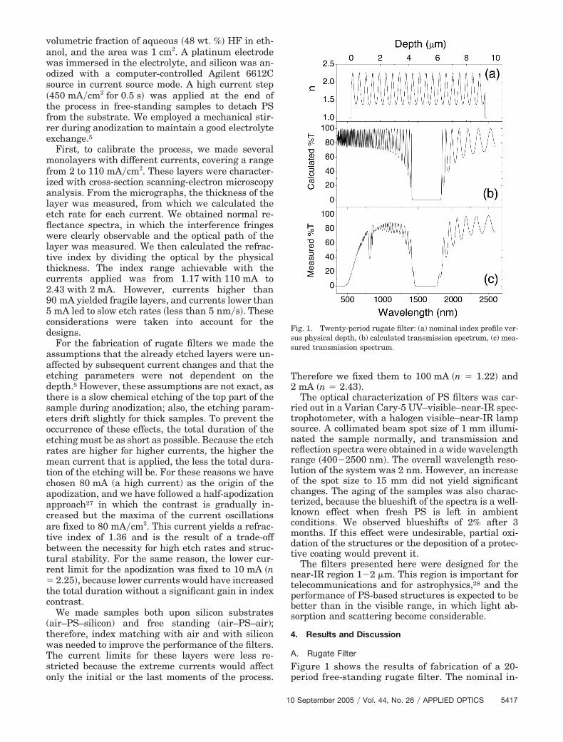
Figure 1 shows the results of fabrication of a 20-period free-standing rugate filter. The nominal in-
Fig. 1. Twenty-period rugate filter: (a) nominal index profile ver-sus physical depth, (b) calculated transmission spectrum, (c) mea-sured transmission spectrum.
10 September 2005 � Vol. 44, No. 26 � APPLIED OPTICS 5417
dex profile is shown in Fig. 1(a). We used Eq. (2) forthe calculation of the n(x) curve, and we display itsprofile versus physical thickness. Figure 1(b) showsthe calculation of the transmittance spectrum fromthe nominal curve. The calculation is implementedby the transfer-matrix method that is typical formultilayers. The gradual refractive-index varia-tions were treated as discrete layers, so each oscil-lation was meshed into a certain number of layersuntil the result was independent of this number.For the sake of clarity in the interpretation, weconsidered neither silicon absorption (real index)nor dispersion (index not dependent on wave-length). In the visible range this is not a good ap-proximation, but it will help the reader understandthe transmission spectrum that an ideal samplewould have. Figure 1(c) shows the measured trans-mittance spectrum, in which a stop band centeredat 1600 nm is clearly observable. On both sides, onecan see strong sidelobes in both the measured andthe calculated spectra. The experiment also shows atransmission decay below 800 nm that is due to PSabsorption, which was not taken into account in thecalculations. A weak second-harmonic peak and aslightly narrower stop band are also observable inFig. 1(c). These discrepancies are due to limitationson the assumptions made in Section 3. In spite ofthese small imperfections, the agreement found be-
tween the experiment and calculations demon-strates that the etching process is well controlled.The optical density (absolute value of the decimallogarithm of the transmittance) of this filter reachesa maximum of 3.4 at the center of the stop band.
B. Apodization
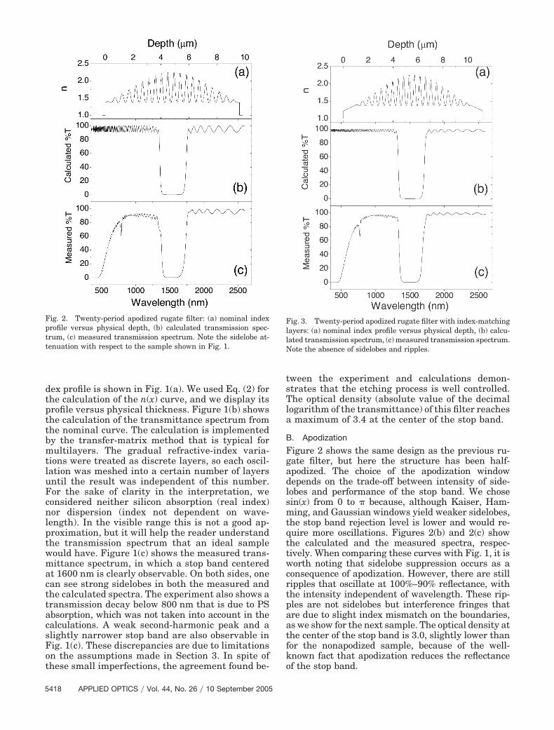
Figure 2 shows the same design as the previous ru-gate filter, but here the structure has been half-apodized. The choice of the apodization windowdepends on the trade-off between intensity of side-lobes and performance of the stop band. We chosesin(x) from 0 to � because, although Kaiser, Ham-ming, and Gaussian windows yield weaker sidelobes,the stop band rejection level is lower and would re-quire more oscillations. Figures 2(b) and 2(c) showthe calculated and the measured spectra, respec-tively. When comparing these curves with Fig. 1, it isworth noting that sidelobe suppression occurs as aconsequence of apodization. However, there are stillripples that oscillate at 100%–90% reflectance, withthe intensity independent of wavelength. These rip-ples are not sidelobes but interference fringes thatare due to slight index mismatch on the boundaries,as we show for the next sample. The optical density atthe center of the stop band is 3.0, slightly lower thanfor the nonapodized sample, because of the well-known fact that apodization reduces the reflectanceof the stop band.
Fig. 2. Twenty-period apodized rugate filter: (a) nominal indexprofile versus physical depth, (b) calculated transmission spec-trum, (c) measured transmission spectrum. Note the sidelobe at-tenuation with respect to the sample shown in Fig. 1.
Fig. 3. Twenty-period apodized rugate filter with index-matchinglayers: (a) nominal index profile versus physical depth, (b) calcu-lated transmission spectrum, (c) measured transmission spectrum.Note the absence of sidelobes and ripples.
5418 APPLIED OPTICS � Vol. 44, No. 26 � 10 September 2005
C. Index Matching
If we add index-matching layers on the boundaries ofthe design described above, we obtain the structureshown in Fig. 3. As was mentioned in Section 3, wecan apply currents as high as 100 mA, because theyare present only in the initial and last moments of theetching process. These layers improve the indexmatching because the jump becomes 1 to 1.22 insteadof 1 to 1.36. This difference, with a layer with a linearprofile, yields weaker interference ripples, as con-firmed in Figs. 3(b) and 3(c), in which oscillationsfrom 100% to 95% can be observed. The maximumoptical density of this filter sample remains 3.0.
D. Rugate Filter versus Distributed Bragg Reflector
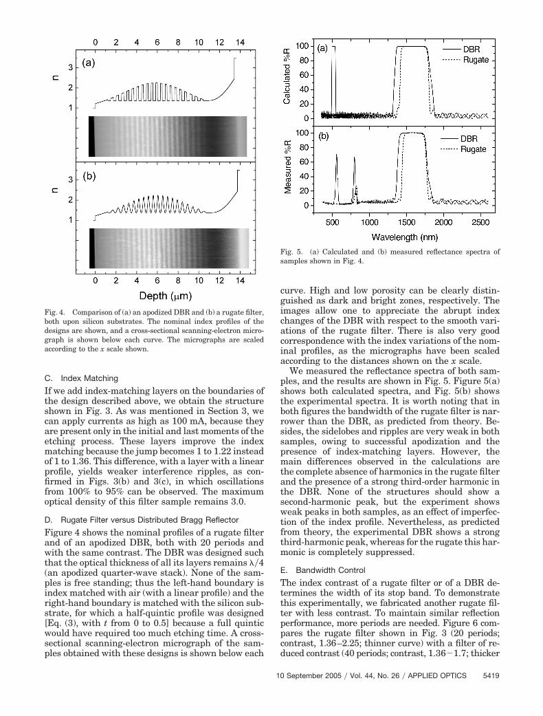
Figure 4 shows the nominal profiles of a rugate filterand of an apodized DBR, both with 20 periods andwith the same contrast. The DBR was designed suchthat the optical thickness of all its layers remains ��4(an apodized quarter-wave stack). None of the sam-ples is free standing; thus the left-hand boundary isindex matched with air (with a linear profile) and theright-hand boundary is matched with the silicon sub-strate, for which a half-quintic profile was designed[Eq. (3), with t from 0 to 0.5] because a full quinticwould have required too much etching time. A cross-sectional scanning-electron micrograph of the sam-ples obtained with these designs is shown below each
curve. High and low porosity can be clearly distin-guished as dark and bright zones, respectively. Theimages allow one to appreciate the abrupt indexchanges of the DBR with respect to the smooth vari-ations of the rugate filter. There is also very goodcorrespondence with the index variations of the nom-inal profiles, as the micrographs have been scaledaccording to the distances shown on the x scale.
We measured the reflectance spectra of both sam-ples, and the results are shown in Fig. 5. Figure 5(a)shows both calculated spectra, and Fig. 5(b) showsthe experimental spectra. It is worth noting that inboth figures the bandwidth of the rugate filter is nar-rower than the DBR, as predicted from theory. Be-sides, the sidelobes and ripples are very weak in bothsamples, owing to successful apodization and thepresence of index-matching layers. However, themain differences observed in the calculations arethe complete absence of harmonics in the rugate filterand the presence of a strong third-order harmonic inthe DBR. None of the structures should show asecond-harmonic peak, but the experiment showsweak peaks in both samples, as an effect of imperfec-tion of the index profile. Nevertheless, as predictedfrom theory, the experimental DBR shows a strongthird-harmonic peak, whereas for the rugate this har-monic is completely suppressed.
E. Bandwidth Control
The index contrast of a rugate filter or of a DBR de-termines the width of its stop band. To demonstratethis experimentally, we fabricated another rugate fil-ter with less contrast. To maintain similar reflectionperformance, more periods are needed. Figure 6 com-pares the rugate filter shown in Fig. 3 (20 periods;contrast, 1.36–2.25; thinner curve) with a filter of re-duced contrast (40 periods; contrast, 1.36�1.7; thicker
Fig. 4. Comparison of (a) an apodized DBR and (b) a rugate filter,both upon silicon substrates. The nominal index profiles of thedesigns are shown, and a cross-sectional scanning-electron micro-graph is shown below each curve. The micrographs are scaledaccording to the x scale shown.
Fig. 5. (a) Calculated and (b) measured reflectance spectra ofsamples shown in Fig. 4.
10 September 2005 � Vol. 44, No. 26 � APPLIED OPTICS 5419

curve). A bandwidth reduction from 350 to 150 nm canbe observed. However, the narrow sample shows anoptical density of 2.0 instead of 3.0.
F. Superposition of Designs
Two rugate filter designs can be combined in threeways: in parallel, in which both profiles are summed;in series, in which one is piled on the top of the other;
and shifted,29 which is midway between the othertwo. We present here a parallel combination of tworugate filters centered at 1500 and 1900 nm with 40and 32 periods, respectively. The resultant oscillatingfunction was apodized and index matched in thesame way as the previous samples. Figure 7 showsthe calculated and measured transmission spectra. Adouble stop band can be observed, with neither side-lobes nor ripples. The maximum optical densitiesmeasured were 3.0 at 1500 nm and 2.5 at 1900 nm.The weaker reflectance of the latter is due to thesmaller number of oscillation periods. The agreementbetween calculation and experiment for this sampleconfirms the possibility of combining different de-signs for creating multi-stop-band filters that blockany desired wavelength band.
5. Conclusions
We have experimentally studied porous silicon-basedrugate filters. We demonstrated sidelobe attenuationby means of half-apodization of the structures with asinusoidal window. Reduction of interference rippleswas experimentally observed through the insertion ofindex-matching layers on the boundaries of the struc-ture. We compared an apodized distributed Braggreflector with a rugate filter, and the main differencesobserved were a stronger and wider stop band for theDBR and a suppressed third-order harmonic forthe rugate filter. We also studied the effect of varyingthe index contrast of rugate filters, in which band-width variations were observed. Finally, we showedan example of a parallel combination of two differentdesigns through the fabrication of a multi-stop-bandfilter. The easy and cheap procedures involved in thefabrication process make these results attractive forapplications in many fields, such as telecommu-nications, chemical and biological sensors, and astro-physics.
We thank the Instituto de Astrofisica de Canariasfor offering its facilities and help for the opticalcharacterization. We acknowledge financial supportfrom Science and Technology Ministry of SpainProject MAT 2002-00044, Ministero dell’ Instruzi-one, dell’ Università della Ricera project IT1872,and integrated action HI2003-0180. C. J. Oton ac-knowledges a fellowship granted by Cajacanariasand the University of La Laguna.
References1. M. J. Sailor, in Properties of Porous Silicon, L. T. Canham, ed.
(IEE Inspec, 1997), p. 364.2. C. J. Oton, M. Ghulinyan, Z. Gaburro, P. Bettotti, L. Pavesi, L.
Pancheri, S. Gialanella, and N. E. Capuj, “Scattering rings asa tool for birefringence measurements in porous silicon,”J. Appl. Phys. 94, 6334–6340 (2003).
3. L. Pavesi, “Porous silicon dielectric multilayers and microcavi-ties,” Riv. Nuovo Cim. 20, 1–76 (1997).
4. V. Agarwal and J. A. del Rio, “Tailoring the photonic band gapof a porous silicon dielectric mirror,” Appl. Phys. Lett. 82,1512–1514 (2003).
5. M. Ghulinyan, C. J. Oton, G. Bonetti, Z. Gaburro, and L.
Fig. 7. Double stop-band filters centered at 1500 and 1900 nmwith 40 and 32 periods, respectively: (a) nominal profile versusphysical depth, (b) experimental and calculated transmissionspectra.
Fig. 6. Comparison of rugate filters made with different indexcontrasts: (a) nominal profile of a 20-period sample with 1.36�2.25 contrast, (b) 40-period sample with 1.36�1.7 contrast, (c)transmission spectra of the high-contrast sample (thinner curve)and the low-contrast sample (thicker curve).
5420 APPLIED OPTICS � Vol. 44, No. 26 � 10 September 2005

Pavesi, “Free-standing porous silicon single and multiple cav-ities,” J. Appl. Phys. 93, 9724–9729 (2003).
6. P. Ferrand, R. Romestain, and J. C. Vial, “Photonic band-gapproperties of a porous silicon periodic planar waveguide,” Phys.Rev. B 63, 115106 (2001).
7. L. Dal Negro, C. J. Oton, Z. Gaburro, L. Pavesi, P. Johnson, A.Lagendijk, R. Righini, M. Colocci, and D. S. Wiersma, “Lighttransport through the band-edge states of Fibonacci quasicrys-tals,” Phys. Rev. Lett. 90, 055501 (2003).
8. R. Sapienza, P. Costantino, D. Wiersma, M. Ghulinyan, C. J.Oton, and L. Pavesi, “Optical analogue of electronic Bloch os-cillations,” Phys. Rev. Lett. 91, 263902 (2003).
9. C. Mazzoleni and L. Pavesi, “Application to optical componentsof dielectric porous silicon multilayers,” Appl. Phys. Lett. 67,2983–2985 (1995).
10. L. Pavesi, C. Mazzoleni, A. Tredicucci, and V. Pellegrini, “Con-trolled photon emission in porous silicon microcavities,” Appl.Phys. Lett. 67, 3280–3282 (1995).
11. Y. Zhou, P. A. Snow, and P. St. J. Russell, “Strong modificationof photoluminescence in erbium-doped porous silicon micro-cavities,” Appl. Phys. Lett. 77, 2440–2442 (2000).
12. P. Allcock and P. A. Snow, “Time-resolved sensing of organicvapors in low modulating porous silicon dielectric mirrors,”J. Appl. Phys. 90, 5052–5057 (2001).
13. C. S. Bartholomew, M. D. Morrow, H. T. Betz, J. L. Grieser,R. A. Spence, and N. P. Murarka, “Rugate filters by laser flashevaporation of SiOxNy on room-temperature polycarbonate,” J.Vac. Sci. Technol. A 6, 1703–1707 (1988).
14. W. J. Gunning, R. L. Hall, F. J. Woodberry, W. H. Southwell,and N. S. Gluck, “Codeposition of continuous composition ru-gate filters,” Appl. Opt. 28, 2945–2948 (1989).
15. A. F. Jankowski, L. R. Schrawyer, and P. L. Perry, “Reactivesputtering of molybdenum-oxide gradient-index filters,” J.Vac. Sci. Technol. A 9, 1184–1187 (1991).
16. P. L. Swart, P. V. Bulkin, and B. M. Lacquet, “Rugate filtermanufacturing by electron cyclotron resonance plasma-enhanced chemical vapor deposition of SiNx,” Opt. Eng. 36,1214–1219 (1997).
17. K. Kaminska, T. Brown, G. Beydaghyan, and K. Robbie,“Rugate filters grown by glancing angle deposition,” in Appli-cations of Photonic Technology 5, R. A. Lessard, G. A. Lam-propoulos, and G. W. Schini, eds., Proc. SPIE 4833, 633–639(2003).
18. A. J. McPhun, Q. H. Wu, and I. J. Hodgkinson, “Birefringentrugate filters,” Electron. Lett. 34, 360–361 (1998).
19. M. G. Berger, R. Arens-Fischer, M. Thönissen, M. Krüger, S.Billat, H. Lüth, S. Hilbrich, W. Theiss, and P. Grosse, “Di-electric filters made of PS: advanced performance by oxida-tion and new layer structures,” Thin Solid Films 297, 237–240 (1997).
20. F. Cunin, T. A. Schmedake, J. R. Link, Y. Li, J. Koh, S. Bhatia,and M. Sailor, “Biomolecular screening with encoded porous-silicon photonic crystals,” Nature Mater. 1, 39–41 (2002).
21. K. Kaminska, T. Brown, G. Beydaghyan, and K. Robbie, “Vac-uum evaporated porous silicon photonic interference filters,”Appl. Opt. 42, 4212–4219 (2003).
22. B. G. Bovard, “Rugate filter theory: an overview,” Appl. Opt.32, 5427–5442 (1993).
23. W. H. Southwell and R. L. Hall, “Rugate filter sidelobe sup-pression using quintic and rugated quintic matching layers,”Appl. Opt. 28, 2949–2951 (1989).
24. W. H. Southwell, “Using apodization functions to reduce side-lobes in rugate filters,” Appl. Opt. 28, 5091–5094 (1989).
25. C. C. Striemer and P. M. Fauchet, “Dynamic etching of siliconfor broadband antireflection applications,” Appl. Phys. Lett.81, 2980–2982 (2002).
26. W. H. Southwell, “Gradient-index antireflection coatings,”Opt. Lett. 8, 584–586 (1983).
27. H. A. Abu-Safia, A. I. Al-Sharif, and I. O. Abu Aljarayesh,“Rugate filter sidelobe suppression using half-apodization,”Appl. Opt. 32, 4831–4835 (1993).
28. A. R. Offer and J. Bland-Hawthorn, “Rugate filters for OH-suppressed imaging,” in Optical Astronomical Instrumenta-tion, S. D’Odorics, ed., Proc. SPIE 3355, 970–978 (1998).
29. W. H. Southwell, “Extended-bandwidth reflector designs byusing wavelets,” Appl. Opt. 36, 314–318 (1997).
10 September 2005 � Vol. 44, No. 26 � APPLIED OPTICS 5421