Porous alumina infiltrated with melt and its dynamic...
7
CERAMICS INTERNATIONAL Available online at www.sciencedirect.com Ceramics International 40 (2014) 6293–6299 Porous alumina infiltrated with melt and its dynamic analysis during pressureless infiltration H.M. Chen a,b,n , Y.F. Yin a , H.B. Dong b , Y. Tong a , M. Luo a , X. Li a a School of Physics and Electrical Information, Ningxia University, Yinchuan 750021, PR China b Department of Engineering, University of Leicester, Leicester LE1 7RH, United Kingdom Received 4 November 2013; received in revised form 17 November 2013; accepted 18 November 2013 Available online 26 November 2013 Abstract Porous alumina ceramic bodies prepared by freeze casting were pressureless infiltrated with molten metal. The dynamic process during pressureless infiltration was analyzed through numerical calculations. The results indicated the ceramic bodies to present well interconnected pore channels that can be easily infiltrated under the capillary driving force. The numerical calculation indicated that the dynamic behavior during pressureless infiltration is strongly affected by the size of pore channels and the wetting angle, but it is relatively unaffected by the surface tension of melt, the coefficient of viscosity and the gravity exerted on the melt. & 2013 Elsevier Ltd and Techna Group S.r.l. All rights reserved. Keywords: Porous alumina; Pressureless infiltration; Dynamic analysis 1. Introduction Porous ceramics with open pore structures have attracted a great deal of attention since their wide applications in industrial area. These applications include liquid or gas filters, supports for catalytic agents, bone tissue engineering, and so on [1–3]. Over the past few decades, the manufacturing processes for the production of porous ceramics have been developed by many researchers and scientists all over the world. Among those processes, freeze casting, which can make full use of the dendritic growth of a freezing vehicle and create interconnected channels in the bulk, seems becoming a significant interest for researchers due to its many advantages [4–11]. Mukai et al. [12] molded sol–gel based materials into a monolithic microhoneycomb structure by freezing unidirec- tionally. Zhang et al. [13] fabricated aligned pore structures combining the freeze casting and gel casting. Porter et al. [14] fabricated porous, anisotropic ceramic scaffolds with a hier- archy of architectural alignment in multiple directions through magnetic field aligned freeze casting. Recently, in order to align with both excellent properties of metal and ceramics, the porous ceramic preform prepared by freeze casting was used to fabricate metal matrix composites materials. The reinforced ceramic particles embedded in matrix can improve the fracture toughness and the metal matrix can also enhance the toughness through preventing the crack propagation and the reinforced fibers pulling out. For example, Binner et al. [15] produced the composites at atmospheric pressure by infiltrating Al–Mg alloys into 20% dense Al 2 O 3 foams with highly interconnected porosity and investigated the processing window. Roy et al. [16] carried out experimental studies on samples containing about 44% alumina ceramic and 56% aluminium-based alloy (Al–12Si). Zhang et al. [17] produced alumina-reinforced niobium aluminide composites by reactive Al melt pressure-assisted infiltration into Nb 2 O 5 – Al 2 O 3 precursors. The main focuses of this article are to use ice as a template to prepare laminate porous alumina with well interconnected pore channels, and to use pressureless infiltration method to prepare the Al 2 O 3 /Nb–Ti–Al–Cr composites, which has a potential application in industrial area. For the purpose of deep understanding into the dynamic process during pressure- less infiltration, the dynamic process of molten melt infiltrated www.elsevier.com/locate/ceramint 0272-8842/$ - see front matter & 2013 Elsevier Ltd and Techna Group S.r.l. All rights reserved. http://dx.doi.org/10.1016/j.ceramint.2013.11.088 n Corresponding author. E-mail address: [email protected] (H.M. Chen).
Transcript of Porous alumina infiltrated with melt and its dynamic...
CERAMICSINTERNATIONAL
Available online at www.sciencedirect.com
0272-8842/$ - sehttp://dx.doi.org/
nCorrespondinE-mail addre
Ceramics International 40 (2014) 6293–6299www.elsevier.com/locate/ceramint
Porous alumina infiltrated with melt and its dynamic analysis duringpressureless infiltration
H.M. Chena,b,n, Y.F. Yina, H.B. Dongb, Y. Tonga, M. Luoa, X. Lia
aSchool of Physics and Electrical Information, Ningxia University, Yinchuan 750021, PR ChinabDepartment of Engineering, University of Leicester, Leicester LE1 7RH, United Kingdom
Received 4 November 2013; received in revised form 17 November 2013; accepted 18 November 2013Available online 26 November 2013
Abstract
Porous alumina ceramic bodies prepared by freeze casting were pressureless infiltrated with molten metal. The dynamic process duringpressureless infiltration was analyzed through numerical calculations. The results indicated the ceramic bodies to present well interconnected porechannels that can be easily infiltrated under the capillary driving force. The numerical calculation indicated that the dynamic behavior duringpressureless infiltration is strongly affected by the size of pore channels and the wetting angle, but it is relatively unaffected by the surface tensionof melt, the coefficient of viscosity and the gravity exerted on the melt.& 2013 Elsevier Ltd and Techna Group S.r.l. All rights reserved.
Keywords: Porous alumina; Pressureless infiltration; Dynamic analysis
1. Introduction
Porous ceramics with open pore structures have attracted agreat deal of attention since their wide applications inindustrial area. These applications include liquid or gas filters,supports for catalytic agents, bone tissue engineering, and soon [1–3]. Over the past few decades, the manufacturingprocesses for the production of porous ceramics have beendeveloped by many researchers and scientists all over theworld. Among those processes, freeze casting, which can makefull use of the dendritic growth of a freezing vehicle and createinterconnected channels in the bulk, seems becoming asignificant interest for researchers due to its many advantages[4–11]. Mukai et al. [12] molded sol–gel based materials into amonolithic microhoneycomb structure by freezing unidirec-tionally. Zhang et al. [13] fabricated aligned pore structurescombining the freeze casting and gel casting. Porter et al. [14]fabricated porous, anisotropic ceramic scaffolds with a hier-archy of architectural alignment in multiple directions throughmagnetic field aligned freeze casting.
e front matter & 2013 Elsevier Ltd and Techna Group S.r.l. All ri10.1016/j.ceramint.2013.11.088
g author.ss: [email protected] (H.M. Chen).
Recently, in order to align with both excellent properties ofmetal and ceramics, the porous ceramic preform prepared byfreeze casting was used to fabricate metal matrix compositesmaterials. The reinforced ceramic particles embedded in matrixcan improve the fracture toughness and the metal matrix canalso enhance the toughness through preventing the crackpropagation and the reinforced fibers pulling out. For example,Binner et al. [15] produced the composites at atmosphericpressure by infiltrating Al–Mg alloys into 20% dense Al2O3
foams with highly interconnected porosity and investigated theprocessing window. Roy et al. [16] carried out experimentalstudies on samples containing about 44% alumina ceramic and56% aluminium-based alloy (Al–12Si). Zhang et al. [17]produced alumina-reinforced niobium aluminide compositesby reactive Al melt pressure-assisted infiltration into Nb2O5–
Al2O3 precursors.The main focuses of this article are to use ice as a template
to prepare laminate porous alumina with well interconnectedpore channels, and to use pressureless infiltration method toprepare the Al2O3/Nb–Ti–Al–Cr composites, which has apotential application in industrial area. For the purpose ofdeep understanding into the dynamic process during pressure-less infiltration, the dynamic process of molten melt infiltrated
ghts reserved.
H.M. Chen et al. / Ceramics International 40 (2014) 6293–62996294
into laminated alumina porous ceramic bodies was alsoanalyzed through numerical calculation.
2. Experimental methods
2.1. Materials and characterization
The alumina powders obtained from Hongsheng ScientificCorporation Limited (Zhejiang, China) were used as thematerials for the preparation of laminated alumina porousceramic bodies. Its size distributed from 100 nm to 300 nm.The slurry contents were 15%, 25% and 30% volume aluminapowders mixed with pure water respectively. The Nb–35Ti–20Al–10Cr (atomic fraction) ingot was chosen as infiltratedalloy. Its liquidus temperature is 1780 1C. The morphologies ofthe porous ceramic bodies and the composite materialsprepared by pressureless infiltration were evaluated by ascanning electron microscope (SEM, Model JEOL JSM7500F, SSX-550, Japan). The measurements were carried outat 20 keV accelerating voltage.
2.2. Preparation of porous alumina bodies
The slurry with different volume percentage of aluminapowder was milled for 12 h so as to improve its liquidity. TheTH-908 ceramic dispersant obtained from Shandong TaiheCorporation Limited (Shandong, China) was used to raise thedispersiveness of the slurry. The quantity of dispersant used inthe slurry is 5% (volume fraction). In order to remove anyphysically stirred bubbles existed in the slurry, it wasprocessed in a vacuum drying oven for 10 min. The resultantslurry was poured into a tubular polytetrafluoroethylene moldand frozen by liquid nitrogen. The cylindrical container bottom
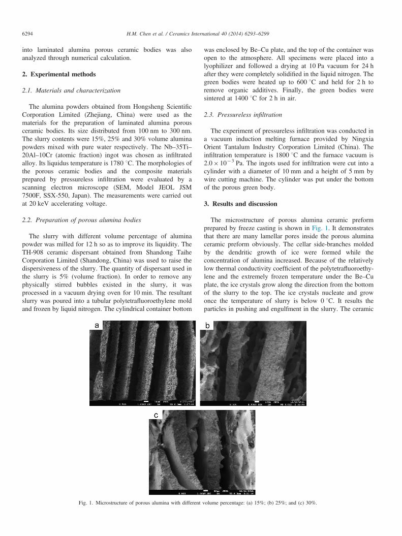
Fig. 1. Microstructure of porous alumina with different
was enclosed by Be–Cu plate, and the top of the container wasopen to the atmosphere. All specimens were placed into alyophilizer and followed a drying at 10 Pa vacuum for 24 hafter they were completely solidified in the liquid nitrogen. Thegreen bodies were heated up to 600 1C and held for 2 h toremove organic additives. Finally, the green bodies weresintered at 1400 1C for 2 h in air.
2.3. Pressureless infiltration
The experiment of pressureless infiltration was conducted ina vacuum induction melting furnace provided by NingxiaOrient Tantalum Industry Corporation Limited (China). Theinfiltration temperature is 1800 1C and the furnace vacuum is2.0� 10�3 Pa. The ingots used for infiltration were cut into acylinder with a diameter of 10 mm and a height of 5 mm bywire cutting machine. The cylinder was put under the bottomof the porous green body.
3. Results and discussion
The microstructure of porous alumina ceramic preformprepared by freeze casting is shown in Fig. 1. It demonstratesthat there are many lamellar pores inside the porous aluminaceramic preform obviously. The cellar side-branches moldedby the dendritic growth of ice were formed while theconcentration of alumina increased. Because of the relativelylow thermal conductivity coefficient of the polytetrafluoroethy-lene and the extremely frozen temperature under the Be–Cuplate, the ice crystals grow along the direction from the bottomof the slurry to the top. The ice crystals nucleate and growonce the temperature of slurry is below 0 1C. It results theparticles in pushing and engulfment in the slurry. The ceramic
volume percentage: (a) 15%; (b) 25%; and (c) 30%.

H.M. Chen et al. / Ceramics International 40 (2014) 6293–6299 6295
particles are expelled from the forming ices and entrappedwithin channels between the lamellar ice crystals during thefreezing process. Simultaneously, the growth of the ice is
Fig. 2. Microstructure of Al2O3/Nb–Ti–Al–Cr
Fig. 3. Distribution of Nb, Ti, A
blocked by particles. The green body with ceramic walls,lamellar pores or cellar side-branches has been molded afterice sublimation. The smaller cellar pores suspended on the
composite (Al2O3: 15%, 25%, and 30%).
l, Cr and O in composites.
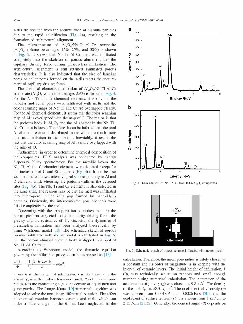
Fig. 4. EDS analysis of Nb–35Ti–20Al–10Cr/Al2O3 composites.
Fig. 5. Schematic sketch of porous ceramic infiltrated with molten metal.
H.M. Chen et al. / Ceramics International 40 (2014) 6293–62996296
walls are resulted from the accumulation of alumina particlesdue to the rapid solidification (Fig. 1a), resulting in theformation of architectural alignment.
The microstructure of Al2O3/Nb–Ti–Al–Cr composite(Al2O3 volume percentage: 15%, 25%, and 30%) is shownin Fig. 2. It shows that Nb–Ti–Al–Cr melt was infiltratedcompletely into the skeleton of porous alumina under thecapillary driving force during pressureless infiltration. Thearchitectural alignment is still retained laminated porouscharacteristics. It is also indicated that the size of lamellarpores or cellar pores formed on the walls meets the require-ment of capillary driving force.
The chemical elements distribution of Al2O3/Nb-Ti-Al-Crcomposite (Al2O3 volume percentage: 25%) is shown in Fig. 3.For the Nb, Ti and Cr chemical elements, it is obvious thelamellar and cellar pores were infiltrated with melts and thecolor scanning maps of Nb, Ti and Cr are overlapped clearly.For the Al chemical elements, it seems that the color scanningmap of Al is overlapped with the map of O. The reason is thatthe preform body is Al2O3 and the Al content in the Nb–Ti–Al–Cr ingot is lower. Therefore, it can be inferred that the totalAl chemical elements distributed in the walls are much morethan its distribution in the intervals. Inevitably, it results thefact that the color scanning map of Al is more overlapped withthe map of O.
Furthermore, in order to determine chemical composition ofthe composites, EDX analysis was conducted by energydispersive X-ray spectrometer. For the metallic layers, theNb, Ti, Al and Cr chemical elements were detected except forthe inclusions of C and Si elements (Fig. 4a). It can be alsoseen that there are two intensive peaks corresponding to Al andO elements while choosing the preform walls as the detectedsites (Fig. 4b). The Nb, Ti and Cr elements is also detected inthe same sites. The reasons may be that the melt was infiltratedinto micro-pores which is a gap formed by nano-Al2O3
particles. Obviously, the interconnected pore channels werefilled completely by the melt.
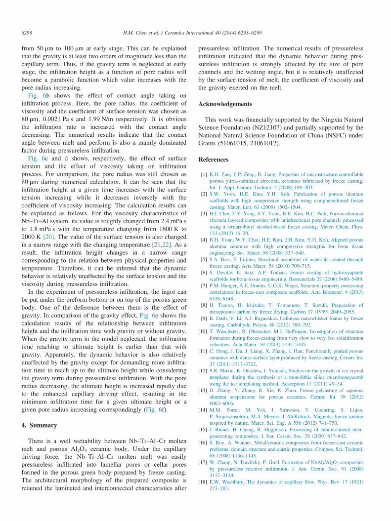
Concerning with the transportation of molten metal in theporous preform subjected to the capillarity driving force, thegravity and the resistance of the viscosity, the dynamics ofpressureless infiltration has been analyzed theoretically byusing Washburn model [18]. The schematic sketch of porousceramic infiltrated with molten metal is illustrated in Fig. 5,i.e., the porous alumina ceramic body is dipped in a pool ofNb–Ti–Al–Cr melt.
According to Washburn model, the dynamic equationgoverning the infiltration process can be expressed as [18]
dhðtÞdt
¼ 18η
ð2sR cos θ
h�ρgR2Þ
where h is the height of infiltration, t is the time, η is theviscosity, s is the surface tension of melt, R is the mean poreradius, θ is the contact angle, ρ is the density of liquid melt andg the gravity. The Runge–Kutta [19] numerical algorithm wasadopted to solve the non-linear differential equation. The effectof chemical reaction between ceramic and melt, which canmake a little change on the R, has been neglected in the
calculation. Therefore, the mean pore radius is safely chosen asa constant and its order of magnitude is in keeping with theinterval of ceramic layers. The initial height of infiltration, h(0), was technically set as an random and small enoughnumber during numerical calculation. The parameter of theacceleration of gravity (g) was chosen as 9.8 m/s2. The densityof the melt (ρ) is 5850 kg/m3. The coefficient of viscosity (η)was chosen from 0.0018 Pa s to 0.0026 Pa s [20], and thecoefficient of surface tension (s) was chosen from 1.85 N/m to2.13 N/m [21,22]. Generally, the contact angle (θ) depends on

H.M. Chen et al. / Ceramics International 40 (2014) 6293–6299 6297
temperature and the processing environment, even depends onexperimental duration [23], therefore, it was arbitrarily andsafely chosen from 0 to π/4 in the calculation. The numericalresults are shown in Fig. 6.
Fig. 6a shows the relationship between the infiltration height(h) and the infiltration time (t) during pressureless infiltration.
Fig. 6. Numerical results: (a) infiltration height vs. infiltration time for deferent poreeffect of viscosity; (e) the effect of gravity on infiltration; and (f) the minimum inultimate height.
At the early stage of development of the infiltration process,the slopes of the curves are greater than the latter stage for allcases of the pore radius, implying that infiltration rate is higherat the early stage than the latter stage. From the predictedevolution of infiltration, it can be also seen that the infiltrationheight at a given time increases with the pore radius increasing
radius; (b) the effect of contact angle; (c) the effect of surface tension; (d) thefiltration time for deferent pore radius while the infiltration height reaches the
H.M. Chen et al. / Ceramics International 40 (2014) 6293–62996298
from 50 μm to 100 μm at early stage. This can be explainedthat the gravity is at least two orders of magnitude less than thecapillary term. Thus, if the gravity term is neglected at earlystage, the infiltration height as a function of pore radius willbecome a parabolic function which value increases with thepore radius increasing.
Fig. 6b shows the effect of contact angle taking oninfiltration process. Here, the pore radius, the coefficient ofviscosity and the coefficient of surface tension was chosen as80 μm, 0.0021 Pa s and 1.99 N/m respectively. It is obviousthe infiltration rate is increased with the contact angledecreasing. The numerical results indicate that the contactangle between melt and perform is also a mainly dominatedfactor during pressureless infiltration.
Fig. 6c and d shows, respectively, the effect of surfacetension and the effect of viscosity taking on infiltrationprocess. For comparison, the pore radius was still chosen as80 μm during numerical calculation. It can be seen that theinfiltration height at a given time increases with the surfacetension increasing while it decreases inversely with thecoefficient of viscosity increasing. The calculation results canbe explained as follows. For the viscosity characteristics ofNb–Ti–Al system, its value is roughly changed from 2.4 mPa sto 1.8 mPa s with the temperature changing from 1600 K to2000 K [20]. The value of the surface tension is also changedin a narrow range with the changing temperature [21,22]. As aresult, the infiltration height changes in a narrow rangecorresponding to the relation between physical properties andtemperature. Therefore, it can be inferred that the dynamicbehavior is relatively unaffected by the surface tension and theviscosity during pressureless infiltration.
In the experiment of pressureless infiltration, the ingot canbe put under the preform bottom or on top of the porous greenbody. One of the deference between them is the effect ofgravity. In comparison of the gravity effect, Fig. 6e shows thecalculation results of the relationship between infiltrationheight and the infiltration time with gravity or without gravity.When the gravity term in the model neglected, the infiltrationtime reaching to ultimate height is earlier than that withgravity. Apparently, the dynamic behavior is also relativelyunaffected by the gravity except for demanding more infiltra-tion time to reach up to the ultimate height while consideringthe gravity term during pressureless infiltration. With the poreradius decreasing, the ultimate height is increased rapidly dueto the enhanced capillary driving effect, resulting in theminimum infiltration time for a given ultimate height or agiven pore radius increasing correspondingly (Fig. 6f).
4. Summary
There is a well wettability between Nb–Ti–Al–Cr moltenmelt and porous Al2O3 ceramic body. Under the capillarydriving force, the Nb–Ti–Al–Cr molten melt was easilypressureless infiltrated into lamellar pores or cellar poresformed in the porous green body prepared by freeze casting.The architectural morphology of the prepared composite isretained the laminated and interconnected characteristics after
pressureless infiltration. The numerical results of pressurelessinfiltration indicated that the dynamic behavior during pres-sureless infiltration is strongly affected by the size of porechannels and the wetting angle, but it is relatively unaffectedby the surface tension of melt, the coefficient of viscosity andthe gravity exerted on the melt.
Acknowledgements
This work was financially supported by the Ningxia NaturalScience Foundation (NZ12107) and partially supported by theNational Natural Science Foundation of China (NSFC) underGrants (51061015, 21061012).
References
[1] K.H. Zuo, Y.P. Zeng, D. Jiang, Properties of microstructure-controllableporous yttria-stabilized ziroconia ceramics fabricated by freeze casting,Int. J. Appl. Ceram. Technol. 5 (2008) 198–203.
[2] S.W. Yook, H.E. Kim, Y.H. Koh, Fabrication of porous titaniumscaffolds with high compressive strength using camphene-based freezecasting, Mater. Lett. 63 (2009) 1502–1504.
[3] H.J. Choi, T.Y. Yang, S.Y. Yoon, B.K. Kim, H.C. Park, Porous alumina/zirconia layered composites with unidirectional pore channels processedusing a tertiary-butyl alcohol-based freeze casting, Mater. Chem. Phys.133 (2012) 16–20.
[4] B.H. Yoon, W.Y. Choi, H.E. Kim, J.H. Kim, Y.H. Koh, Aligned porousalumina ceramics with high compressive strengths for bone tissueengineering, Scr. Mater. 58 (2008) 537–540.
[5] S.A. Barr, E. Luijten, Structural properties of materials created throughfreeze casting, Acta Mater. 58 (2010) 709–715.
[6] S. Deville, E. Saiz, A.P. Tomsia, Freeze casting of hydroxyapatitescaffolds for bone tissue engineering, Biomaterials 27 (2006) 5480–5489.
[7] P.M. Hunger, A.E. Donius, U.G.K. Wegst, Structure–property-processingcorrelations in freeze-cast composite scaffolds, Acta Biomater. 9 (2013)6338–6348.
[8] H. Tamon, H. Ishizaka, T. Yamamoto, T. Suzuki, Preparation ofmesoporous carbon by freeze drying, Carbon 37 (1999) 2049–2055.
[9] R. Dash, Y. Li, A.J. Ragauskas, Cellulose nanowhisker foams by freezecasting, Carbohydr. Polym. 88 (2012) 789–792.
[10] T. Waschkies, R. Oberacker, M.J. Hoffmann, Investigation of structureformation during freeze-casting from very slow to very fast solidificationvelocities, Acta Mater. 59 (2011) 5135–5145.
[11] C. Hong, J. Du, J. Liang, X. Zhang, J. Han, Functionally graded porousceramics with dense surface layer produced by freeze-casting, Ceram. Int.37 (2011) 3717–3722.
[12] S.R. Mukai, K. Onodera, I. Yamada, Studies on the growth of ice crystaltemplates during the synthesis of a monolithic silica microhoneycombusing the ice templating method, Adsorption 17 (2011) 49–54.
[13] D. Zhang, Y. Zhang, R. Xie, K. Zhou, Freeze gelcasting of aqueousalumina suspensions for porous ceramics, Ceram. Int. 38 (2012)6063–6066.
[14] M.M. Porter, M. Yeh, J. Strawson, T. Goehring, S. Lujan,P. Siripasopsotorn, M.A. Meyers, J. McKittrick, Magnetic freeze castinginspired by nature, Mater. Sci. Eng. A 556 (2012) 741–750.
[15] J. Binner, H. Chang, R. Higginson, Processing of ceramic-metal inter-penetrating composites, J. Eur. Ceram. Soc. 29 (2009) 837–842.
[16] S. Roy, A. Wanner, Metal/ceramic composites from freeze-cast ceramicpreforms: domain structure and elastic properties, Compos. Sci. Technol.68 (2008) 1136–1143.
[17] W. Zhang, N. Travitzky, P. Greil, Formation of NbAl3/Al2O3 compositesby pressureless reactive infiltration, J. Am. Ceram. Soc. 91 (2008)3117–3120.
[18] E.W. Washburn, The dynamics of capillary flow, Phys. Rev. 17 (1921)273–283.

H.M. Chen et al. / Ceramics International 40 (2014) 6293–6299 6299
[19] C.W. Xu, Introduction to Numerical Methods, High Education Press,Beijing, 1985.
[20] K. Zhou, H.P. Wang, J. Chang, B. Wei, Surface tension measurement ofmetastable liquid Ti–Al–Nb alloys, Appl. Phys. A 105 (2011) 211–214.
[21] D.L. Davidson, K.S. Chan, The fatigue and fracture resistance of a Nb–Cr–Ti–Al Alloy, Metall. Mater. Trans. A 30A (2008) 1999–2007.
[22] P.F. Paradis, T. Ishikawa, S. Yoda, Non-contact measurements of surfacetension and viscosity of niobium, zirconium, and titanium using anelectrostatic levitation furnace, Int. J. Thermophys. 23 (2002) 825–842.
[23] J. Yang, O.J. Ilegbusi, Kinetics of silicon–metal alloy infiltration intoporous carbon, Compos.: Part A 31 (2000) 617–625.