POLITECNICO DI TORINO Repository ISTITUZIONALE · Elena Pinotti 2017 * This dissertation is...
254
18 February 2019 POLITECNICO DI TORINO Repository ISTITUZIONALE Dynamic characterization of high performance materials for application to cultural heritage / Pinotti, Elena. - (2017). Original Dynamic characterization of high performance materials for application to cultural heritage Publisher: Published DOI:10.6092/polito/porto/2690722 Terms of use: Altro tipo di accesso Publisher copyright (Article begins on next page) This article is made available under terms and conditions as specified in the corresponding bibliographic description in the repository Availability: This version is available at: 11583/2690722 since: 2017-11-09T15:27:41Z Politecnico di Torino
Transcript of POLITECNICO DI TORINO Repository ISTITUZIONALE · Elena Pinotti 2017 * This dissertation is...

18 February 2019
POLITECNICO DI TORINORepository ISTITUZIONALE
Dynamic characterization of high performance materials for application to cultural heritage / Pinotti, Elena. - (2017).Original
Dynamic characterization of high performance materials for application to cultural heritage
Publisher:
PublishedDOI:10.6092/polito/porto/2690722
Terms of use:Altro tipo di accesso
Publisher copyright
(Article begins on next page)
This article is made available under terms and conditions as specified in the corresponding bibliographic description inthe repository
Availability:This version is available at: 11583/2690722 since: 2017-11-09T15:27:41Z
Politecnico di Torino
Doctoral Dissertation
Doctoral Program in Architectural and Landscape Heritage (29th Cycle)
Dynamic characterization of high
performance materials for application
to cultural heritage
By
Elena Pinotti ******
Supervisor:
Prof. Rosario Ceravolo
Doctoral Examination Committee:
Prof. Stefano Gabriele, Referee, University of Roma Tre
Prof.ssa Giuseppa Novello, Referee, Politecnico di Torino
Prof. Francesco Romeo, Referee, University of Roma La Sapienza
Prof. Salvatore Russo, Referee, University of IUAV
Prof.ssa Cecilia Surace, Referee, Politecnico di Torino
Politecnico di Torino
2017
Declaration
I hereby declare that, the contents and organization of this dissertation
constitute my own original work and does not compromise in any way the rights
of third parties, including those relating to the security of personal data.
Elena Pinotti
2017
* This dissertation is presented in partial fulfillment of the requirements for
Ph.D. degree in the Graduate School of Politecnico di Torino (ScuDo).


Acknowledgment
All my gratitude to my supervisor Prof. Rosario Ceravolo and Prof. Andrea
De Marchi for placing their confidence in me and inspiring my work with their
precious advices. My most affectionate thanks to the researchers Luca Zanotti
Fragonara and Antonino Quattrone for their helps and supports during these years.
The work presented in this dissertation is the result of a "Youth Project", a
PhD grant funded by the Italian Ministry of Education and Scientific Research,
with the subject on "Advanced materials for structural applications in the cultural
heritage field".


Abstract
Natural hazards, such as earthquakes, can compromise the integrity of the
cultural heritage with potentially devastating effects. The reduction of the seismic
vulnerability of the cultural heritage constitutes a question of maximum
importance especially in countries where vast cultural heritage combines with a
medium or high seismic risk, such as in Italy. From the second half of the last
century, the scientific community edited a number of important documents and
charts for the conservation, reinforcement and restoration of the cultural heritage.
The aim is to mitigate the seismic vulnerability of the cultural heritage.
This research focused on high performance materials for applications aimed
to structural and seismic protection of cultural heritage, with a special focus on
historical masonry structures. In particular, the final aim is to define a self-
diagnosis strategy for fibres, yarns and ties in view of efficient, non-invasive and
reversible interventions on cultural heritage buildings.
In order to set up the scene, the present thesis starts by introducing the reader
to the seismic protection of cultural heritage thorough an extensive review on high
performance materials, strengthening techniques and systems, taking care to
highlight real world applications and limitations of their use.
The second step of this work concerns in the mechanical and rheological
characterization of high performance material fibres. The materials investigated
are essentially Kevlar® 29 (para-aramid), Carbon and Silicon Carbide. To reach
this goal, an extensive experimental testing campaign was conducted on fibres and

yarns in accordance with specific protocols. A further step was defining
appropriate damage indices for different materials, with a special focus on
Kevlar® 29. Within the same research programme, a novel testing machine was
also designed in cooperation with the Laboratory of Electronic Measurements of
the Politecnico di Torino. A prototype-testing machine for dynamic testing on
high resistance fibres was built using recycled materials and components. A
distinctive feature of this machine is that it can apply to the sample any kind of
dynamic excitation (random, impulse, harmonic etc.).
A second testing campaign concerned the durability of Kevlar® 29 fibres,
which are known to be sensitive to long-term exposure to UV radiation.
Accordingly, for this campaign, the samples were artificially damaged by using
UV lamps. The analysis of the resonance profiles allowed for the extraction of
parameters such as the elastic moduli, quality factors, and non-linear coefficient
for a set of fibres. In particular, non-linearity parameters derived from the Krylov-
Bogoliubov method demonstrated to be consistent with the damage affecting the
fibres.
The final chapter of the dissertation concerns a new concept for a tie endowed
with self-diagnosis properties, which are obtained by integrating a low cost testing
device into the tie model. The self-diagnosis properties system of existing
structures has an important role in the preservation of the cultural heritage because
the best therapy is preventive maintenance. Specifically, the para-aramid tie
system proposed for the reinforcement of historic building constitutes a non-
invasive, reversible and repeatable intervention, as required by the main
guidelines on preservation of cultural heritage.


Contents
1. Structural conservation and repair of the cultural heritage ................................ 2
1.1 National and international deontological guidelines for the protection of
cultural heritage .................................................................................................... 2
1.1.1 International context ......................................................................... 2
1.1.2 The Italian national context .............................................................. 6
1.2 Safety assessment of the architectural heritage ....................................... 7
1.3 Introduction to high performance fibre materials for historical
constructions ........................................................................................................ 9
1.3.1 Why use high performance fibre materials .................................... 9
1.3.2 Application of high performance fibre materials to masonry
constructions ................................................................................................... 12
1.3.3 Limitations in the use of high performance fibre materials on
masonry constructions .................................................................................... 15
2. High performance materials ............................................................................. 22
2.1 Definition of composite materials ......................................................... 23
2.2 Composite materials: classification ....................................................... 24
2.3 High performance materials: fibres ....................................................... 24
2.3.1 Fibre types ....................................................................................... 25
2.3.2 Fibre architecture ............................................................................ 28
2.4 High performance materials: matrix ...................................................... 31
2.5 Why choose a high performance material ............................................. 33
2.6 Commonly used fibres for structural applications ................................. 39
2.6.1 Glass fibres ..................................................................................... 39

2.6.2 Carbon fibres ................................................................................... 43
2.6.3 Aramid fibres .................................................................................. 47
2.7 Brief history of polymers and composites used in construction industry
............................................................................................................................ 50
2.7.1 First generation (1930s-1940s) ....................................................... 50
2.7.2 Second generation (1950s-1960s) ................................................... 53
2.7.3 Third generation (1970s-1980s) ...................................................... 54
2.7.4 Fourth generation (1990s) ............................................................... 55
2.8 Composites for engineering applications .............................................. 57
3. Using high performance materials for strengthening interventions: a literature
review ............................................................................................................... 60
3.1 Background ............................................................................................ 60
3.2 Strengthening actions ............................................................................ 62
3.3 Repairing and strengthening techniques ................................................ 64
3.3.1 Injection .......................................................................................... 64
3.3.2 Local reconstruction named “cuci-scuci” ....................................... 64
3.3.3 External or internal reinforcement ............................................... 66
3.3.4 Stitching and local tying ................................................................. 66
3.3.5 Repointing and reinforced repointing ............................................. 66
3.3.6 Tie bars ........................................................................................... 67
3.3.7 Structural and element substitution ................................................. 68
3.3.8 Dismantling and remounting .......................................................... 69
3.3.9 Continuous and discrete confinement (jacketing)........................... 69
3.3.10 Reinforced concrete and masonry edge-beams ....................... 70
3.3.11 Enlargement .................................................................................. 70
3.3.12 Buttressing, suspension and strutting ............................................ 70
3.3.13 Frictional contact, post-tension, and pre-compression ................. 72
3.3.14 Anchoring ..................................................................................... 72
3.3.15 Direct intervention on foundations ............................................... 73
3.3.16 Interventions on soil beneath foundation ...................................... 73

3.3.17 Seismic isolation ........................................................................... 73
3.4 Repairing and strengthening systems .................................................... 74
3.4.1 Externally bonded reinforcement .................................................... 75
3.4.2 Near surface mounted reinforcement .............................................. 76
3.4.3 Mechanically fastened FRP-system ................................................ 76
3.5 Interventions on masonry buildings using FRP ..................................... 77
3.5.1 Improvement of Connections to Activate Box Behaviour .............. 78
3.5.2 Increase of Strength and Compactness of Walls............................. 81
3.5.3 Strengthening of arches and vaults ................................................. 86
3.5.4 Strengthening and stiffening of floors ............................................ 91
3.5.5 Confinement of masonry columns .................................................. 92
3.6 Numerical investigations on the possible use of aramid fibres for a
permanent strengthening intervention on the Fossano belfry ............................ 95
3.6.1 The Fossano belfry description ....................................................... 95
3.6.2 Finite Element (FE) model calibration ........................................... 97
3.6.3 The AFRP strengthening intervention ............................................ 99
3.6.4 Analysis and results.................................................................... 101
3.6.5 Comparison with traditional strengthening techniques................. 104
4. A prototype-testing machine for the dynamic characterization of high
performance materials .................................................................................... 106
4.1 Introduction ......................................................................................... 107
4.2 Prototype-testing machine description ................................................ 110
4.3 The resonant spring-mass approach .................................................... 114
4.4 The containment structure and its effects ............................................ 118
4.5 Quality Factor limitations .................................................................... 121
5. Experimental investigation on high-strength fibres and results ..................... 126
5.1 Experimental investigation on pristine samples .................................. 127
5.1.1 Samples investigated ..................................................................... 128
5.1.2 Test procedure of forced tests ....................................................... 129
Survey on nonlinear system identification in structural dynamics ........ 140
5.1.3 Nonlinear identification of the backbone curve ............................ 149
5.1.4 Dissipation properties and quality factor: experimental evaluation
...................................................................................................................... 152
6. Experimental investigation and results on damaged Kevlar® 29 samples .... 156
6.1 Effects of UV exposure on high-strength materials: background ....... 157
6.2 Experimental investigation on damaged Kevlar® 29 samples ............ 159
6.2.1 Forced testing on the sample damaged for 792 hours................... 163
6.2.2 Forced testing on the sample damaged for 1272 hours................. 170
6.2.3 Forced testing on the sample damaged for 2040 hours................. 176
6.2.4 Comparison of the results obtained............................................... 185
7. A new concept for a tie element with self-diagnosis properties .................... 190
7.1 Structural Health Monitoring .............................................................. 191
7.2 The concept of a tie with self-diagnosis properties ............................. 192
8. References ...................................................................................................... 202

List of Figures
Figure 1: market share of textile fibres and composite types. Source (Duflou,
et al., 2012). ........................................................................................................... 10
Figure 2: historic development (a) and geographical distribution (b) of articles
dealing with LCC and HPM. Source (Ilg, et al., 2016). ........................................ 17
Figure 3: classification scheme of composite materials. ................................. 24
Figure 4: types of fibres. Source (CNR-DT 200/2004, 2004). ........................ 26
Figure 5: classification scheme of the most widespread commercially
available high-performance fibres. ........................................................................ 27
Figure 6: fibre architecture. Source (Mallick, 1997). ...................................... 28
Figure 7: braided fabrics. Source (Nivitex.Fibreglass.and.Resins, 2017) and
(Composites, 2014). ............................................................................................... 30
Figure 8: disordered glass fibres and random mat. Source (CNR-DT
200/2004, 2004). .................................................................................................... 30
Figure 9: stress-strain curve of the main high-performance materials. Source
(CNR-DT 200/2004, 2004). ................................................................................... 35
Figure 10: glass fibre manufacture, a schematic representation. Source
(Hollaway, 1993). .................................................................................................. 40
Figure 11: the basic tetrahedral structure of glass fibre Source (Gowayed,
2014). ..................................................................................................................... 43
Figure 12: Manufacturing process of carbon fibre. Source (Hollaway, 1993).
............................................................................................................................... 45
Figure 13: effect of heat treatment temperature compared to tensile strength
and modulus of elasticity. Source (Campbell, 2010). ............................................ 47
Figure 14: the chemical structure of Kevlar®. Source (Gowayed, 2014). ...... 48
Figure 15: Schematic diagram showing the relative importance of ceramics,
composites, polymers and metals, in mechanical and civil engineering as a
function of time (The time scale is nonlinear). Source: (Ashby, 1987). ................ 51
Figure 16: step in “cuci-scuci” strengthening intervention. ............................ 65
Figure 17: example of “cuci-scuci” intervention. Source (Modena, et al.,
2011). ..................................................................................................................... 65
Figure 18: repointing technique, phases of intervention: placing of the rebars
(a) and of the anchors (b); view of a joints after repointing (before the injection of
the pins’ holes) (c); final view (d). Source (Valluzzi, et al., 2005). ...................... 67

Figure 19: the interventions on S. Giustina (PD, Italy) bell-tower: injections
(a), partial rebuilding (‘cuci-scuci) (b), insertion of bar (c). Source (Modena &
Valluzzi, 2008). ...................................................................................................... 68
Figure 20: propping intervention of lateral wall of church of Onna (AQ).
Source (Modena, et al., 2011). ............................................................................... 71
Figure 21: shoring of facade with cables and wooden frames (Chiesa di S.
Marco, L’Aquila). Source (Modena, et al., 2011). ................................................ 71
Figure 22: a) splitting failure for EB-FRP laminates; b) laminates used for
MF-FRP systems. Source (Ascione, et al., 2009). ................................................. 76
Figure 23: fasteners used for MF-FRP systems. Source (Ascione, et al., 2009).
............................................................................................................................... 77
Figure 24: wet lay up system. Source (CNR-DT 200/2004, 2004). ................ 77
Figure 25: a), b) the north and west elevation of the masonry building, and
position of CFRP wrapping interventions. Source (Borri & Castori, 2009). ......... 80
Figure 26: a), b) east and north elevation of the masonry building with
horizontal and vertical SRG reinforcement. Source (Borri & Castori, 2009). ...... 80
Figure 27: diagonal compression tests. Source (Borri, et al., 2009). .............. 82
Figure 28: a) kerbs realised with carbon fibres placed up to the roof and the
ceiling, and b) horizontal and vertical kerbs placed on internal and external walls.
Source (Credali, 2009). .......................................................................................... 83
Figure 29: horizontal and vertical CFRP kerbs on internal and external walls.
Source (Credali, 2009). .......................................................................................... 84
Figure 30: restoration intervention realised on the masonry external façade.
Source (Credali, 2009). .......................................................................................... 85
Figure 31: strengthening intervention with hybrid reinforced carbon-aramid
fibres systems. Source (Credali, 2009). ................................................................. 85
Figure 32: cracks and deformation in the vaults with relative displacement till
30cm. Source (Croci, 2000). .................................................................................. 89
Figure 33: the new ribs, made of a central timber nucleus and external aramid
fibres. In the background, the steel belt to anchor the base of the arches which
sustain the roof is visible. Source (Croci, 2000). ................................................... 90
Figure 34: Complesso di Venaria Reale (TO) – Strengthening intervention
with strips placed to the intradox and extrados of the vaults. Source (Credali,
2002). ..................................................................................................................... 91
Figure 35: strengthening intervention with AFRP in Villa Reale in Monza
(sx), and Real Albergo dei Poveri a Napoli (dx). Source (Olympus, 2016) and
(ResinProget, 2012). .............................................................................................. 93
Figure 36: the Fossano belfry; wood ramps located inside the tower. ............ 96
Figure 37: the belfry of the Fossano Cathedral with the strengthening
intervention. ........................................................................................................... 97
Figure 38: the FE model: subdivision in macroelements, and updated values
of the elastic moduli. Source (Ceravolo, et al., 2014). .......................................... 98
Figure 39: different position of the Kevlar® reinforcements investigated. .. 100
Figure 40: pushover curves, in x direction (Kevlar® 29 with E = 70GPa). .. 101
Figure 41: pushover curves, in x direction (Kevlar® 49 with E = 160 GPa).
............................................................................................................................. 102
Figure 42: maximum displacement vs. ratio between the areas of the
horizontal and vertical stripes. ............................................................................. 103
Figure 43: maximum displacement vs. ratio between the areas of the vertical
and horizontal stripes. .......................................................................................... 103
Figure 44: contour plots of the failure index for some load steps. ................ 104
Figure 45: pushover curves relative to the unreinforced structure, the proposed
intervention and the adoption of traditional techniques. ...................................... 105
Figure 46: real prototype testing machine, and a schematic model. ............. 111
Figure 47: schematic representation of the optical system. .......................... 112
Figure 48: schematic representation of the electromagnetic system. ............ 113
Figure 49: the homemade magnetic circuit. .................................................. 113
Figure 50: Schematic arrangement of tie-rods, with attachment errors. ....... 115
Figure 51: Significant components in the prototype machine....................... 116
Figure 52: non-contact excitation and detection. .......................................... 118
Figure 53: schematic representation of the containment structure. ............... 119
Figure 54: the SiC (Type S) sample tested. ................................................... 128
Figure 55: Kevlar® 29 sample tested. ........................................................... 128
Figure 56: carbon sample tested. ................................................................... 129
Figure 57: Silicon Carbide: values of frequency response recorded around
resonance for increasing levels of driving force. ................................................. 131
Figure 58: Silicon Carbide: frequency response measured around resonance
for increasing levels of driving force. The maximum value is indicated by red dot.
............................................................................................................................. 131
Figure 59: Kevlar® 29: values of frequency response recorded around
resonance for increasing levels of driving force. ................................................. 133
Figure 60: Kevlar® 29: frequency response measured around resonance for
increasing levels of driving force. The maximum value is indicated by red dot. 133
Figure 61: Carbon: values of frequency response recorded around resonance
for increasing levels of driving force. .................................................................. 138

Figure 62: Carbon: frequency response measured around resonance for
increasing levels of driving force. The maximum value is indicated by red dot. 138
Figure 63: flowchart of the general numerical procedure. Source (Song, et al.,
2013). ................................................................................................................... 147
Figure 64: amplitude-response curves for a varying strength of nonlinearities
γ. Source (Kalmar-Nagy & Balachandran, 2011). ............................................... 149
Figure 65: Silicon Carbide: frequency response measured around resonance
for increasing levels of driving force. The red dots highlight the maximum of the
response curve and the dashed red line is the estimated backbone response curve.
............................................................................................................................. 150
Figure 66: Kevlar® 29: frequency response measured around resonance for
increasing levels of driving force. The red dots highlight the maximum of the
response curve and the dashed red line is the estimated backbone response curve.
............................................................................................................................. 151
Figure 67: Carbon: frequency response measured around resonance for
increasing levels of driving force. The red dots highlight the maximum of the
response curve and the dashed red line is the estimated backbone response curve.
............................................................................................................................. 151
Figure 68: weatherometer with a Xenon lamp, emitting UV rays at 340 nm at
an irradiance of 1.1 W/m2 used in an experimental tests. Source (Said, et al.,
2006). ................................................................................................................... 158
Figure 69: geometrical details of a UV lamp chosen to cause the damage on
Kevlar®29 samples. Source (OSRAM, 2017). .................................................... 160
Figure 70: power spectra distribution of Ultra-Vitalux® lightbulb subdivided
for the different components of the electromagnetic spectrum. Source (OSRAM,
2017). ................................................................................................................... 161
Figure 71: the experimental setup used to focus the light flux onto fibre
samples. ................................................................................................................ 162
Figure 72: damaged Kevlar® 29 sample (792 hours) ................................... 163
Figure 73: Sample exposed 792 hours: frequency response measured around
resonance for increasing levels of driving force. The excitation range is 2 V – 10
V. .......................................................................................................................... 168
Figure 74: sample exposed 792 hours: frequency response measured around
resonance for increasing levels of driving force. The excitation range is 2 V – 10
V. The red dots highlight the maximum of the response curve and the dashed red
line is the estimated backbone response curve. ................................................... 169
Figure 75: damaged Kevlar® 29 sample (1272 hours) ................................. 170

Figure 76: sample exposed 1272 hours: frequency response measured around
resonance for increasing levels of driving force. The excitation range is 2 V – 10
V. .......................................................................................................................... 174
Figure 77: sample exposed 1272 hours: frequency response measured around
resonance for increasing levels of driving force. The excitation range is 2 V – 10
V. The red dots highlight the maximum of the response curve and the dashed red
line is the estimated backbone response curve. ................................................... 175
Figure 78: damaged Kevlar® 29 sample (2040 hours) ................................. 176
Figure 79: sample exposed 2040 hours: frequency response measured around
resonance for increasing levels of driving force. The excitation range is 2 V – 10
V. .......................................................................................................................... 181
Figure 80: sample exposed 2040 hours: frequency response measured around
resonance for increasing levels of driving force. The excitation range is 2 V – 10
V. The red dots highlight the maximum of the response curve and the dashed red
line is the estimated backbone response curve. ................................................... 182
Figure 81: variations of measured nonlinear coefficient X with respect to UV
exposure time. ...................................................................................................... 184
Figure 82: measured variations of Q-factor versus drive level for different
exposure times to UV. ......................................................................................... 186
Figure 83: typical Structural Health Monitoring strategy.. ........................... 191
Figure 84: possible setup configurations investigated: a) vertical sample, and
suspended mass of 1.345 kg, b) horizontal sample, and mass of 0.150 kg, c)
vertical sample, and suspended mass of 45 kg. ................................................... 194
Figure 85: different setup investigated with different ball lens position....... 195
Figure 86: the concept of control and self-diagnosis system. ....................... 196
Figure 87: the concept of the system for self-diagnosis: demonstrative sketch
of a possible application. ..................................................................................... 196
Figure 88: the belfry of the Fossano Cathedral with the strengthening
intervention. ......................................................................................................... 197
Figure 89: particular of the last safety measure works. ................................. 197

List of Tables
Table 1: cost of materials per unit force. Source (Burgoyne & Balafas, 2007)
............................................................................................................................... 19
Table 2: typical glass composition of glass fibres used to reinforced composite
materials Source (Hollaway, 1994). ...................................................................... 41
Table 3: Mechanical properties of some glass fibres. Source (Kinsella, et al.,
2001) ...................................................................................................................... 42
Table 4: mechanical properties of some carbon fibres. Source (Hearle, 2001)
............................................................................................................................... 44
Table 5: mechanical properties of some carbon fibres. Source (Gowayed,
2014). ..................................................................................................................... 49
Table 6: typical mechanical properties for glass, aramid, and carbon fibres.
Source (Hollaway, 1993). ...................................................................................... 49
Table 7: materials properties after model-updating. Source (Ceravolo, et al.,
2014). ..................................................................................................................... 99
Table 8: Recap of the main features of samples tested. ................................ 129
Table 9: SiC: strain values calculated from the numerical data acquired during
the forced tests. .................................................................................................... 132
Table 10: Kevlar® 29: strain values calculated from the numerical data
acquired during the forced tests. .......................................................................... 134
Table 11: Carbon: strain values calculated from the numerical data acquired
during the forced tests. ......................................................................................... 139
Table 12: main Q and damping values, estimated using the half-power
bandwidth method, was computed for the 5 V response, for Kevlar® 29 and
carbon, and for 1V response for SiC, respectively. ............................................. 154
Table 13: Technical details of an OSRAM Ultra-Vitalux®. Source (OSRAM,
2017). ................................................................................................................... 160
Table 14: strain values calculated from the numerical data acquired during the
forced tests. .......................................................................................................... 164
Table 15: strain values calculated from the numerical data acquired during
the forced tests. .................................................................................................... 170
Table 16: strain values calculated from the numerical data acquired during the
forced tests. .......................................................................................................... 176
Table 17: results recap................................................................................... 187


2 Elena Pinotti – Dynamic characterization of high-performance
materials for application to cultural heritage
Chapter 1
Structural conservation and repair
of the cultural heritage
In this first chapter the main issues involved in the seismic protection and
analysis of the cultural heritage are introduced. In particular, the most relevant
Italian national and international codes, such as the Directive PCM 2011 and the
ISCARSAH guidelines, are reviewed.
In a second part of this chapter the role of high performance materials for the
structural conservation and repair of the architectural heritage is explained.
Disadvantages and points of strengths were briefly discussed, and lacks of
knowledge were underlined, with a special focus on masonry structures
applications.
1.1 National and international deontological guidelines
for the protection of cultural heritage
1.1.1 International context
The difficulty, or even lack, of communication between architects, art
historians and engineers has always been one of the main obstacles in the analysis
and conservation of the cultural heritage. In 2003, during the 14th General
Assembly of ICOMOS (International Council on Monuments and Sites), a very

Structural conservation and repair of the cultural heritage 3
important document was produced and approved. The ISCARSAH guidelines
(ICOMOS, 2003) claim that the conservation, reinforcement and restoration of the
architectural heritage require a multidisciplinary approach.
An example of interdisciplinary approach is the interaction that may occur
between historical research and structural diagnosis. On the one hand, historical
research could discover particular facts involving structural behaviour, on the
other historical questions could be find answer taking into consideration the
global or local structural behaviour.
The ISCARSAH guidelines combine the different approaches involved in the
structural conservation. This combination of both qualitative and quantitative
approaches, has been very difficult due to the different philosophies on traditional
and innovative techniques. The guidelines introduce also the concept of holistic
approach for the evaluation of a building as a whole entity, and not a combination
of singular elements.
In addition, the ISCARSAH guidelines discriminate in a clear way four
different phases: the data acquisition (the phase of information gathering and
investigation of the structure), the study of the structural behaviour (the
intermediate phase), and the diagnosis and safety evaluation (the last two phases).
The data acquisition phase is particularly important in historic buildings.
The correct evaluation of the structural problems cannot be achieved if there
is lack of information about the structure under investigation. For these reasons,
the ISCARSAH guidelines specify that the “knowledge of the structure” may be
reached by means of the following steps:
definition, description and knowledge of the historic and cultural
significance of the building;
description of the original materials and construction techniques;
historical research of the whole life of the structure. It includes the
changes to its form and any previous structural interventions;
description of the structure in its present state. It include the damage
identification, decay and possible progressive phenomena. This knowledge
may be reached using appropriate types of test;
description of the actions involved, the structural behaviour and types of
materials.

4 Elena Pinotti – Dynamic characterization of high-performance
materials for application to cultural heritage
It is also important to emphasise that all these actions may be carried out at
different levels of detail, but this study have to be cost efficient. It must be
proportional to the importance of the structure/building and the level of
knowledge desired.
Another important consideration is that the restoration of a historical building
must not be considered a part of an end in itself, but a means to an end, which is
the cultural heritage. In fact, no action must be undertaken without distinguished
between benefit and harm to the architectural heritage (except in the case where
urgent interventions are required) and having demonstrated that interventions are
indispensable.
For the restoration, strengthening and conservation of the architectural
heritage, both traditional and innovative methods can be used. Regard to the
“innovative” methods and materials, the guidelines claim that their use has to be
weighed up with “traditional” ones. The compatibility with original materials and
long-term impacts has to be defined, in order to avoid side-effects.
In addition, the monitoring of existing structures has an important role in the
preservation of the cultural heritage. It is clearly explain in the guidelines that
“the best therapy is preventive maintenance” that can only be reached by
means of a structural monitoring. It is necessary not only in the case of a gradual
phenomenon occurring, but also during a “step-by-step procedure of structural
renovation”.
Ian Hume (Forsyth, et al., 2007) claims that the principles of structural
conservation of historic structures can be summarised in five main points:
Conserve as found. Structures should ideally be conserved as they are
found. They should not be taken back to the condition that it is supposed
they might have been in at some period in their history. They must not be
“improved” without well-argued justifications.
Minimal intervention. In many cases it is necessary to make changes
both because of excessive decay or distortion resulting in a problem to the
structural stability, or because changes are necessary to ensure that the
structure may have a future. Any time that changes are made, these have to
be kept to a minimum. Traditional and tested techniques are nowadays
preferable to new methods that could have negative effect on the structure
at some time in the future.
Structural conservation and repair of the cultural heritage 5
Like-for-like repairs. If a repairs are to be necessary, the best solution is
that they are made using the same materials found in the original
construction. Nevertheless, there are cases when to do this could cause a
great loss of fabric, and consequently a loss of detail and history.
Repairs should be reversible. If a repairs are to be necessary, they should
be designed and carried out taking into account the possibility to remove
them. It should be possible to remove repairs from a structure, should it
later prove possible to make better repairs, or if for some reason, the
repairs become redundant. This is the principle of conservation most
difficult to achieve. However, in many cases is not possible to guarantee
the reversibility of repairs.
Repairs should be sympathetic. Repairs need to be in character with the
structure. If it is decided to use modern materials and technique for the
repair, it is necessary that the design fits the general style of the original
structure.
Another author, Bernard Feilden (Feilden, 2003), defines the standard of
ethics and the recommendations that should be taken into consideration in any
conservation work:
the historic evidence must not be destroyed, falsified or removed.
any intervention must be the minimum needed.
any intervention have to be regulated by respect for the aesthetic, historical
and physical integrity of cultural property.
all methods, technologies and materials used during treatment should be
carefully documented.
In addition, all the interventions proposed for the conservation of a historic
building have to be reversible or repeatable, if technically possible, or at least
have not to prejudice a future intervention, in case this could become necessary.
Moreover, the interventions must allow the maximum possible amount of original
material to be conserved, must be compatible in colour, tone, texture, form and
scale. In case additions are necessary and unavoidable, they should be less evident
than original material but, at the same time, identifiable.
However, Feilden adds that the problems arising from historic buildings are
often unique. These problems must be solved from first principles on a trial-and-
error basis. In addition, Feilden claim that architectural conservation does not
share all the objectives of artistic conservation. Indeed, the architectural fabric has
6 Elena Pinotti – Dynamic characterization of high-performance
materials for application to cultural heritage
to function as a structure (resisting dead and live loadings), and have to provide a
suitable internal environment protected against certain type of hazards, such as
fire, earthquake, or vandalism.
In addition, Claudio Modena introduced the concept that structural repair of a
historic building has to be “cautious”. The “cautiousness” principle have to lead
the complete process of the conservation of historic architectural heritage
buildings (Modena, 1995). Indeed, a great number of restorations failed due to not
appropriate applications of modern technologies. These technologies can also
have good performance from a technical point of view, but they can modify the
cultural value of a restored building. From the designer’s point of view, the
principle of “cautiousness” results in two fundamental rules. The first is avoiding
non-essential interventions, and the second is choosing intervention technologies,
which alter as less as possible the chemical, physical, and mechanical properties
of original materials and structures (compatible technologies). In addition, usual
safety and reliability concepts could become inadequate when immaterial values
are involved. The case of human life or historic and artistic assets, is an example.
1.1.2 The Italian national context
In Italy, the first operative documents which has explicitly addressed the
problem of cultural heritage buildings in seismic regions was a regulation of the
Italian Ministry of Cultural Heritage, sometimes referred to as “Documento
Ballardini” (Circolare_n°564., 1997). This document fixed some general criteria
and provided a classification of different types of interventions on historic
buildings in seismic areas. In addition, the document presented an outline regard
the interaction between different disciplines, in order to obtain an adequate depth
of the analysis of the building.
A more recent and important contribution for the seismic protection of
cultural heritage is represented by the Italian Legislative Decree “Codice dei Beni
Culturali e del Paesaggio” (Codice_dei_Beni_Culturali_e_del_Paesaggio, 2004).
Article 29 of this decree, explicitly mentions the seismic protection requirements
of cultural heritage. In addition it states that the seismic upgrade is a part of the
restoration intervention. Moreover, Article 30 impose to the government and local
authorities to provide for the safety and the conservation of historic buildings
owned by them (Lagomarsino, et al., 2010).

Structural conservation and repair of the cultural heritage 7
Recent seismic regulations for cultural heritage structures, such as the Directive
PCM and successive guidelines (Presidenza_del_Consiglio_dei_Ministri, 2011)
(Consiglio_superiore_dei_lavori_pubblici, 2011) in Italy, introduce and encourage
the attainment of an appropriate “level of knowledge”. It can be obtained only
through extended tests and investigations. It is necessary that the level of
knowledge should be appropriate for the type of analysis that the designer is
carrying out. For example, the Directive distinguishes among three different
“levels of evaluation” for the analysis methods: LV1, LV2 and LV3. While the
lower level (LV1) must be applied in the case of seismic assessment at territorial
or urban scale on the entire protected architectural heritage, LV2 must be applied
when the building necessitate of local interventions. The last level (LV3), the
most detailed, must be required in the case of intervention that modify the
structural behaviour of the building, or in the case in which a seismic assessment
of the building is required.
When dealing with a historic building, what is must be done in various steps
include:
identification of the structure
geometric data gathering
historical analysis
survey of the materials and their state of preservation
mechanical characterisation of the materials
soil and foundation analysis
monitoring.
Regarding geometric survey, sophisticated and accurate techniques are
nowadays available, including: laser scanner, interferometry, thermography etc. It
is worthless to say that the acquisition of knowledge meets with the difficulties
normally associated with the assessment of existing structures that must be
preserved (Ceravolo, et al., 2012) (Bednarz, et al., 2014).
1.2 Safety assessment of the architectural heritage
Before undergoing any consideration on the structural safety of historic
structures, it is still worth pointing out that ancient structures were not “designed”
as we expect nowadays, but they were built using rules of the thumb (e.g.
geometric proportions), that were verbally handed down. These rules have been
often guarded as secrets by builder guilds during the middle age, as they were
developed by trial and error, and were modified through the centuries. Some of

8 Elena Pinotti – Dynamic characterization of high-performance
materials for application to cultural heritage
which were even incorporated in the first building codes and survived until the
mid of twentieth century (Beckmann & Bowles, 2004). It is straightforward that
historic structures will or will not (mostly will not) achieve the level of safety
required by modern building codes for each type of structures.
The main rules used in the safety assessment of historic structures may be
classified into different categories, such as:
necessity to adapt structural safety requirements to conservation
requirements (choice of the safety levels),
necessity to adapt the structural safety assessment to the maintenance
strategy, and to the temporal horizon of the intervention (choice of the
nominal life of the intervention),
geometrical and topological complexity (modelling requirements),
mechanical response (mechanical and constitutive models).
Regarding the structural safety assessment, in modern codes the uncertainties
in materials behaviour and actions are usually covered by safety factors, which are
directly associated to the assumed safety level. This approach is possible because
the generalised costs are considered to be acceptable to the community. In the
case of historic structures, the standard approach could be inappropriate,
because it may require very invasive rehabilitation works. As a consequence,
the whole costs are of a cultural nature, and may not be generalised.
After these considerations, when dealing with historic buildings it is
preferable to use a more flexible approach to safety assessment. The final aim is
to guarantee both safety for the users, and reduction of the interventions to the
minimum possible. Consequently, in historic structures, lower safety levels than
in new buildings can be sometimes justified. This because it is possible to
decrease the risks related to the use of the building (e.g. by limiting the access in
some area of the building, or by investing in continuous or periodic monitoring
programs etc.).
However, the most important consideration regarding safety is that the usual
partial factors considered for new buildings (taking into account uncertainties
related to strength of materials) depend on the “level of knowledge” of the
building. Codes such as the Directive (Presidenza_del_Consiglio_dei_Ministri,
2011) in Italy, introduces in explicit way the concept of “confidence factor”. This
factor is conventionally applied to the material strength side, in spite of it actually
Structural conservation and repair of the cultural heritage 9
is intended to cover also model uncertainties. In this case, greater is the level of
knowledge, lower is the value of the “confidence factor”.
Another difference between monumental buildings and standard ones is that
historic buildings are often place of activities that requires very long design life.
Cultural heritage buildings are so particular that is also possible to decide to
do not intervene or to do only limited interventions that permit to achieve a design
life of about few decades. The idea could be preserving the structure for a few
decades, and then waiting for the development of less invasive technologies.
Indeed, innovative technologies are in fact expected to be develop in the near
future, able to ensure longer design life for the building without being too much
invasive (Caprili, et al., 2015).
1.3 Introduction to high performance fibre materials for
historical constructions
1.3.1 Why use high performance fibre materials
The employment of traditional materials for strengthening method cannot be
the best solution in any circumstances. Some methods of seismic upgrading (i.e.
addition of new structural frames or shear walls) have been proven to be
impracticable because they could be either invasive, or too costly or restricted in
use for certain types of structures. Other strengthening methods such as grout
injection, insertion of reinforcing steel, pre-stressing, jacketing, and different
surface treatments have been summarized by some authors (Hamid, et al., 1994)
(Saileysh Sivaraja, et al., 2013) (Ravikumar & Thandavamoorth, 2014). These
methods involve the use of skilled labour and interfere with normal functions of
the building. These traditional and well-known techniques could be inadequate for
applications that should protect the cultural heritage (Sivaraja, et al., 2013)
(Marcari, et al., 2007).
High performance materials (HPM) are now used in different field for
different applications. The acronym HPM is used to indicate a general
characterization of fibre reinforcements for fibre-reinforced concrete (FRC), fibre-
reinforced polymers (FRP), engineered cementitious composites (ECC), and
others (Ilg, et al., 2016) (Lin, et al., 1999) (Li, 2003).
HPM are a class of advanced composite materials that emanated from the
aircraft and space industries. They have been used extensively in the medical,

10 Elena Pinotti – Dynamic characterization of high-performance
materials for application to cultural heritage
sporting goods, automotive and small ship industries and are now finding uses
elsewhere (Shrive, 2006). Figure 1 shows how HPM are used in the different
areas of applications.
HPM are now increasingly used in the construction industry, and offer
considerable potential for greater use in buildings. Nowadays, bridges are the
main application field (Ilg, et al., 2016). Holloway in 2003 (Holloway, 2003)
gives an overview of many applications of FRP and FRP/traditional material
composite structures, even though masonry are never mentioned.
Figure 1: market share of textile fibres and composite types. Source (Duflou, et al.,
2012).
HPM offer a set of advantages over traditional materials in building
construction (Triantafillou & Fardis, 1993) (Oliveira, et al., 2010) (Kendall, 2007)
(Saileysh Sivaraja, et al., 2013). The main features that encouraged the diffusion
of these materials at different levels, are:
high tensile strength,
high stiffness-to-weight ratio,
reduced mass,
fatigue and corrosion resistance (superior durability),
easy in-situ feasibility and adaptability,
ability to mould complex forms, special surface finishes and effects,
offsite fabrication,

Structural conservation and repair of the cultural heritage 11
progressive reduction in production and distribution costs,
modular construction,
improved thermal insulation and lack of cold bridging (Kendall, 2007)
(Sivaraja, et al., 2013) (Selin Ravikumar & Thandavamoorthy, 2014).
No structural failure may occur before fibres failure. Fibres activate their
characteristics along their prevalent distribution, whereas have negligible
properties in the other directions. Despite the large accessibility to various
products (bars, strips, laminates, sheets, cords, grids), made of several reinforcing
materials (carbon, glass, aramid, etc.), and applicable in different modalities on
structures (embedded inside grooves or bed mortar joints, externally bonded or
anchored), design rules for the interventions, feasibility recommendations and
procedures aimed at checking the effectiveness of the technique and monitoring
are still under definition (Valluzzi, 2008).
Given their properties, the main applications of HPM in construction industry
are:
to improve the global behaviour in seismic zone (tying, connections
among components, strengthening),
to counteract specific incipient or developed damage (high
compression, shear and/or flexural conditions),
to repair very specific local weaknesses depending on the peculiar
construction typology.
Modern techniques of confinement consist of wrapping with FRP sheets or
laminates. They were introduced in engineering practice as an innovative
confinement technique during the last decade as an alternative to wood or steel
ties adopted in the past.
Very thin layers of FRP are sufficient to yield strength and ductility
improvements, thereby allowing for the reconstruction of heritage-protected
buildings without changing the overall appearance (Aiello, et al., 2007) (Ilg, et al.,
2016). More important is the poor invasiveness. An intervention realised with
FRP could be also reversible (Triantafillou & Fardis, 1993) (De Lorenzis, et al.,
2007), as the material applied on the surface is easily removable and do not
require special restoration of the structure. It is important to take into
consideration that the feature which characterize an historical building is the
uniqueness. For this reason, a strengthening intervention is different case by case.
12 Elena Pinotti – Dynamic characterization of high-performance
materials for application to cultural heritage
HPM are perfectly adapted to a specific case (ICOMOS, 2003)
(Codice_dei_Beni_Culturali_e_del_Paesaggio, 2004).
1.3.2 Application of high performance fibre materials to masonry
constructions
In the previous sections the topics of the architectural heritage protection and
conservation were introduced. In particular, the contents of now available
guidelines were described, from national and international point of view. This
because the preservation of cultural heritage buildings is considered a very
important theme in the cultural life of modern societies. Nevertheless, this
complex task requires the definition of proper methodologies, able to take into
consideration, at the same time, their great architectural and cultural value, and
their structural safety (ICOMOS 2001). One of the most important topic in current
research, is the development of efficient and cost effective strengthening
techniques. They have to be able to re-establish the original performance of
cultural heritage buildings, and to prevent their brittle failure, in particular under
earthquake loading (Oliveira, et al., 2010) (Oliveira, et al., 2011). The main
challenge stays in a development of innovative techniques, advanced materials,
and reinforcement processes, which will lead to discover suitable alternatives to
the more traditional solutions that are incompatible in certain cases (technical-
cultural incompatibilities).
Strengthening solutions, based on the external bonding realised with FRP
composites, have become a popular option (both in new construction and for
rehabilitation) (Bakis, et al., 2002) (Yuan, et al., 2004) (Shrive, 2006) (Oliveira, et
al., 2011) (Oliveira, et al., 2010) (ICOMOS, 2003) ((FIB), 2001).
FRP composites have been now increasingly considered for strengthening and
repair of both modern and historic masonry constructions, such as buildings,
bridges, towers, and structural components, such as walls, arches and vaults, piers
and columns.
Masonry structures constitute a significant part of historical constructions in
Europe and particularly in Italy. Many of these structures are structurally
inadequate for current or safe use respect to new seismic code regulations
(Grande, et al., 2008). Older masonry buildings are often unreinforced,
seismically vulnerable and should be retrofitted in order to provide higher strength
and ductility.

Structural conservation and repair of the cultural heritage 13
Common causes of seismic inadequacy are due to (Oliveira, et al., 2010)
(Cardoso, et al., 2005):
structural degradation,
insufficient design loads,
structural damage sustained in a previous earthquake,
improper design or construction,
changes in building occupancy.
These causes involve the need to retrofit or upgrade historic masonry
structures through strengthening techniques. Despite this, masonry structures
were, until recently, largely been ignored as an area of interest for structural
researchers (Garmendia, et al., 2011). In view of the importance of some masonry
structures, the knowledge on this topic, assessment methods and reinforcement
techniques should be acknowledged in comparison with other construction
materials, such as concrete. A large number of analytical studies and experimental
results allowed carry out of design recommendations that are commonly accepted
by the scientific community (Aiello, et al., 2007) (Hamilton III & Dolan, 2001)
(Oliveira, et al., 2011) (Bakis, et al., 2002).
Starting from extension of approaches proposed for concrete structures, and
after the critical evaluation of the impact of generalised interventions on historical
structures (Giuffrè, 1993) (Tomazevic, 1999), researches and studies have been
more and more focused on the specific features of the masonry material, by
recognizing its lack of homogeneity and the large variability of typologies and
constituent basic materials and aggregations (brick, stones, mortar, mixed
arrangements, etc.). This approach has led to a new impulse for the upgrading of
standards devoted to masonry in seismic zone, which often include reference to
specific codes or recommendations on the possible application of FRPs,
unfortunately still very limited (e.g. (CNR-DT 200/2004, 2004)
(ACI_Committee_440, 1996) (ACI_Committee_440., 2001) (Valluzzi, 2008).
A great contribution coming from researches on the reinforcement or upgrade
of masonry structures regards the experimental behaviour of structural elements
and different assemblages. Frequently, the final aim is to characterize the
mechanical behaviour of strengthened elements, in order to define a simplified
model for design and assessment.
The possibility of adopting FRP composites for strengthening masonry
structures was initially investigated by Croci in 1987 (Croci, et al., 1987). In the

14 Elena Pinotti – Dynamic characterization of high-performance
materials for application to cultural heritage
next three decades, great interest was devoted to the reinforcement of arches and
vaults using FRP materials. Several experimental works show that it is a valid
option for the strengthening and/or repair of masonry. Some of these works are
reported below. After Croci’s researches, also Schwegler (1994) (Schwegler,
1994) and Saadatmanesh (1997) (Saadatmanesh, 1997), addressed this topic. The
first contributions about application on masonry structures concerned general
aspects related to the improvement of the flexural capacity and the resistance to
earthquakes (Triantafillou & Fardis, 1997) (Triantafillou, 1998) (Corradi, et al.,
2002) (Shrive, 2006).
Following these initial studies, several experimental works have been carried
out ( (Ehsani M.R., 1997) (Triantafillou, 1998)) showing that this technique is
effectively a valid option to repair or strengthen masonry structures, in particular,
arched ones (Valluzzi, et al., 2001) (Briccoli Bati & Rovero, 2001) (Foraboschi,
2004) (Briccoli Bati & Rovero, 2008). In particular, these research works address
carbon and glass fibres. However, for strengthening old masonry structures,
characterized by low strength and low stiffness values, the use of glass fibres (or
aramid fibres) seems preferable (Oliveira, et al., 2010) (Oliveira, et al., 2011). If
compared with carbon fibres, the lower axial stiffness of GFRP materials leads to
less mechanical compatibility problems in combination with masonry and, thus,
has the advantage of reducing stress concentrations along the (wider) GFRP-
masonry interface. Experimental tests have shown that masonry arches
strengthened with glass fibres exhibit better global ductility characteristics
(Valluzzi, et al., 2001).
More specialised works including experimental campaign, analytical and
numerical simulation on elements have been proposed. Hereafter, some
bibliographical references, with special focus on masonry structures, are reported:
arches and vaults: (Briccoli Bati & Rovero, 2001) (Briccoli Bati &
Rovero, 2000) (Foraboschi, 2004) (Foraboschi, 2001) (Lourenço &
Poças Martins, 2001) (Luciano, et al., 2001) (Valluzzi, et al., 2001)
(Barbieri, et al., 2002) (Basilio, et al., 2004) (Oliveira, et al., 2006)
(Borri, et al., 2007) (De Lorenzis, et al., 2007) (Baratta & Corbi,
2007);
columns and piers: (Micelli, et al., 2004) (Aiello, et al., 2007)
(Aiello, et al., 2005) (Krevaikas & Triantafillou, 2005) (Nurchi &
Valdes, 2005) (Corradi, et al., 2007);
Structural conservation and repair of the cultural heritage 15
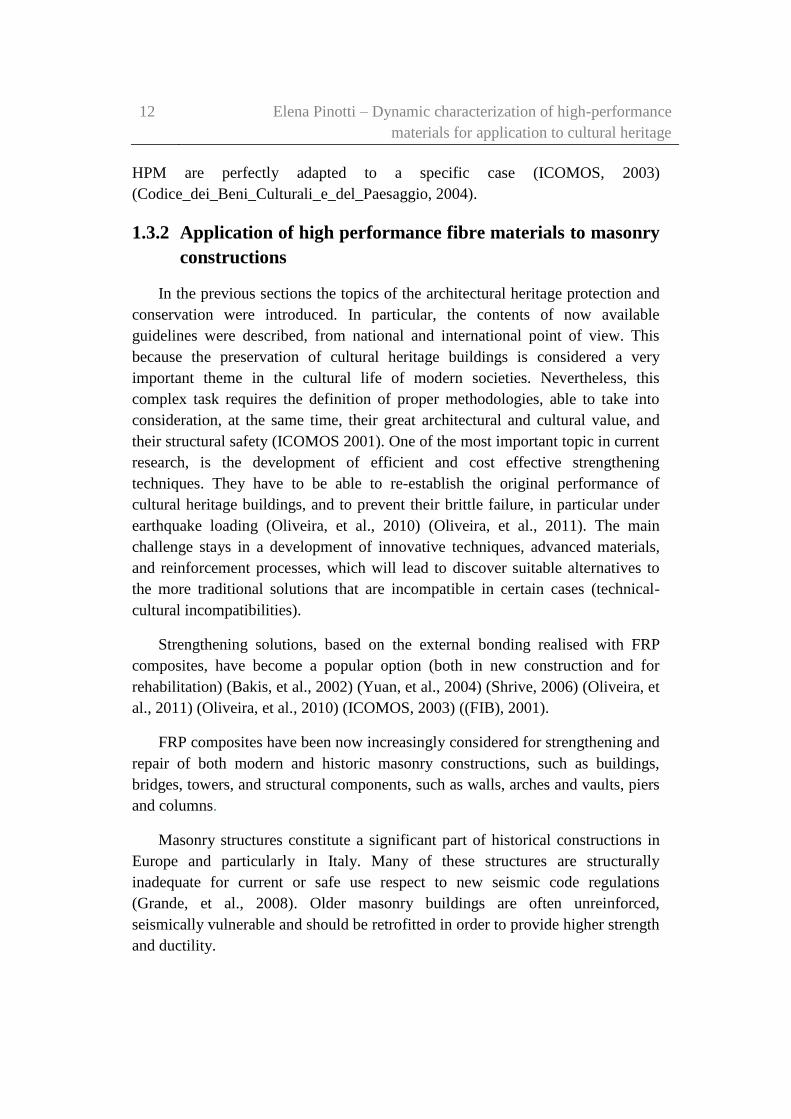
in-plane behaviour of wall panels: (Ehsani M.R., 1997) (Luciano &
Sacco, 1998) (Valluzzi, et al., 2002) (Haroun, et al., 2003) (Cecchi, et
al., 2004) (Ascione, et al., 2005) (Hamid, et al., 2005) (ElGawady, et
al., 2005) (El-Dakhakhni, et al., 2006);
out-of-plane behaviour of wall panels: (Gilstrap & Dolan, 1998) (De
Lorenzis, et al., 2000) (Velazquez-Dimas, et al., 2000) (Hamilton III
& Dolan, 2001) (Hamoush, et al., 2001) (Kiss, et al., 2002) (Kuzik,
2003) (Li, et al., 2004) (Foster, et al., 2005) (Turco, et al., 2006)
(Mosallam, 2007);
bond behaviour: (Ehsani M.R., 1997) (De Lorenzis, et al., 2000)
(Briccoli Bati & Rotunno, 2001) (Casareto, et al., 2003) (Tan, et al.,
2003) (Aiello & Sciolti, 2006).
The choice of using strengthening technique is important because over-
designing interventions on existing structures may usually involve unacceptable
costs. In addition, in the case of architectural heritage, it could entail unacceptable
losses of cultural values, from the historic and artistic point of view (Modena, et
al., 2010).
In recent years, large investments have been concentrated on these topics, in
order to investigate the modalities of application, and the efficacy of FRP
reinforcing systems. A large number of developments have been performed. In
addition, some guidelines for the strengthening and the conservation of existing
structures have been formulated (Grande, et al., 2008) (CNR-DT 200/2004, 2004).
Safeguarding cultural values implies also appropriated selection and design of
the intervention materials and technologies. Attention is to be paid to the
possibilities offered by the traditional solutions and to their possible combinations
with innovative ones.
1.3.3 Limitations in the use of high performance fibre materials
on masonry constructions
In spite of their advantages and versatility, composite materials have not seen
widespread use in civil engineering owing to the lack of knowledge about their
long-term behaviour and high initial costs involved (Richard, et al., 2007).
Prediction of Life-Cycle Costs (LCC) for composites would depend on the
16 Elena Pinotti – Dynamic characterization of high-performance
materials for application to cultural heritage
availability of a practical Life-Cycle Performance Model (LCPM) for composite
materials in construction. Existing LCPM methods that rely on historical
performance records are not useful in the case of composites materials. However,
there is a wealth of information available on the performance of composites in
other sectors such as aerospace, defence, and automobile field. These data-
information may not be used for life-cycle modelling of composites in civil
engineering because of critical differences in environmental exposure, operating
conditions, and loading patterns. (Nystrom, et al., 2003) (Hastak & Halpin, 2000)
(Mishalani & Madanat, 2002). For this reasons, they are quite widespread in
infrastructure rehabilitation projects of concrete structures (Richard, et al., 2007)
(Bakis, et al., 2002) (Ehlen, 1997) (Nystrom, et al., 2003) (Nishizaki, et al., 2006)
(Kong & Frangopol, 2003) (Berg, et al., 2006) (Ehlen, 1999).
LCPM methods is a fundamental tool for the LCC evaluation. It has been
defined as ‘‘economic assessment of an item, area, system, or facility, considering
all the significant costs of ownership over its economic life, expressed in terms of
equivalent dollars’’ (Ehlen, 1997) (Dell’Isola & Kirk, 1981). In generic terms,
LCC would include:
initial cost,
maintenance costs,
operating costs,
replacement or refurbishment cost,
retirement and disposal cost,
other costs such as taxes, depreciation, and additional management
costs (Dell’Isola & Kirk, 1981) (Ehlen, 1997).
In the case of composites, the various costs included under the LCC would
depend on the application. For example, the LCC of a bridge would include
(Burley & Rigden, 1997):
construction costs,
cost of work for each maintenance activity,
road use delay costs from operation and maintenance requirements,
the traffic management costs during maintenance operations.
The difficulty for costs’ evaluation, excluding the initial costs, arises from the
lack of reference data or maintenance records for HPM-composite applications.
The estimation should be made based on HPM properties and data available for
Structural conservation and repair of the cultural heritage 17
conventional material, at a component or system level. Consequently, it is
important to develop a benefit-cost model that allows comparison of different
alternatives, without the need to quantify the benefits in terms of dollar values
(Hastak & Halpin, 2000).
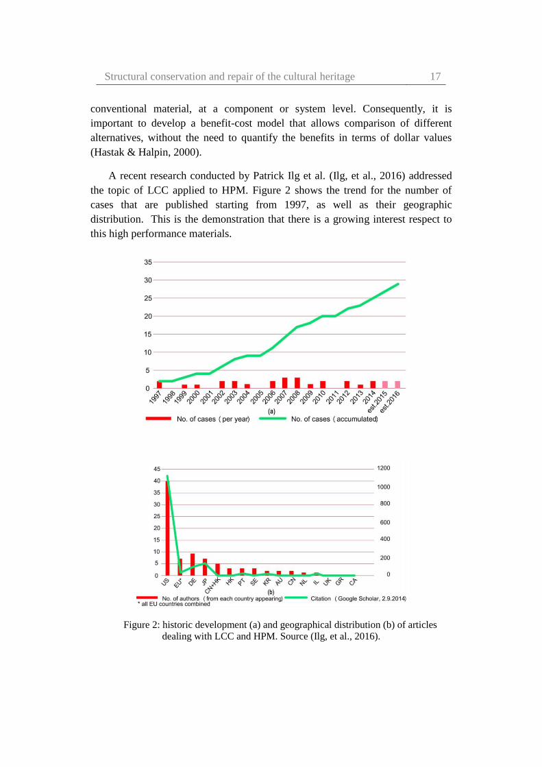
A recent research conducted by Patrick Ilg et al. (Ilg, et al., 2016) addressed
the topic of LCC applied to HPM. Figure 2 shows the trend for the number of
cases that are published starting from 1997, as well as their geographic
distribution. This is the demonstration that there is a growing interest respect to
this high performance materials.
Figure 2: historic development (a) and geographical distribution (b) of articles
dealing with LCC and HPM. Source (Ilg, et al., 2016).

18 Elena Pinotti – Dynamic characterization of high-performance
materials for application to cultural heritage
The same research (Ilg, et al., 2016) shows that LCC is applied to HPM for
structural applications with different levels of detail and quality. The initial results
indicate that total life cycle costs for HPM are on average 10% higher. We urge
the optimization of the cost structure of HPM to achieve the same level of LCC as
conventional construction materials (steel or concrete in this specific case). In
addition, these authors argue for a more holistic approach, which takes into
consideration sustainability criteria throughout the life cycle of HPM based on the
identified drivers of LCC:
external costs, an extended life cycle,
the discount rate and the expected service life.
The main problem is that the true costs of constructing, maintenance, and
disposing of a HPM structures are less certain as compared to the same costs for
traditionally used materials.
Burgoyne and Balafas in 2007 claimed that costs calculated, typically, are 5
or 6 times greater than the cost of steel. These costs were calculated on a
cost/unit-force/unit-length basis. It was argued that those costs applied to
materials in development and they would surely fall rapidly as manufacturing
technology and the competitive market developed (Jungwirth & Windisch, 1995)
(Burgoyne, 1991) (Burgoyne & Balafas, 2007). In addition, they claim that steel
costs have recently risen, maybe because of significantly increased demand in
Chinese economy. That should have improved the market for FRP, but it is clear
in the following table (Table 1) (Burgoyne & Balafas, 2007) that the costs of new
materials are higher in comparison to the costs of steel than they were 20 years
ago and they are significantly higher than they were expected to be. It is widely
believed that aramid and carbon fibre manufacturers have decided to concentrate
on the small-volume, high-price, high-technology markets such as aerospace,
rather than go for the high-volume, low-price, and basic-technology civil
engineering market (Burgoyne & Balafas, 2007).

Structural conservation and repair of the cultural heritage 19
Table 1: cost of materials per unit force. Source (Burgoyne & Balafas, 2007).
MATERIAL
STRENGTH
[MPa]
COST
[£/kN/m]
COST
RATIO
NOTES
Prestressing steel 1700 0.002 1 7-wire strand on coil
Reinforcing steel 460 0.006 3 Includes bending
GFRP 580 0.013 6.5 Excludes bending
Aramid fibre 2600 0.009 4.5 Fibre only
Aramid rope 2000 0.025 12.5 As a rope
AFRP 2000 0.025 12.5 As a pultrusion
CFRP 2000 0.025 12.5 As a pultrusion
(Based on £1 = US$1.77 = €1.50, 2004 prices).
The initial-cost study here reported, shows that concrete structures reinforced
with steel are less expensive than those reinforced with FRP, if only initial costs
are considered. In case of steel structures that could corrode, the use of non-
corrodible materials like FRPs could be a valid alternatives (Burgoyne & Balafas,
2007).
On the contrary, if average total life cycle costs for HPM are considered
(eight cases in this work), they could be very competitive, with a cost that are
8.4% lower. The authors share the belief in a more eco-centric approach and,
therefore, demand further research into a societal type of LCC that improves the
mechanical properties while not ignoring sustainability criteria for new product
systems such as HPM (Ilg, et al., 2016). The debate on this subject is still open.
In 2002 Bakis et al. (Bakis, et al., 2002) claimed that due to the importance of
controlling risk in matters of public safety, standards and codes for FRP materials
used in civil structures have been in development since the 1980s. FRP materials
warrant separate treatment in standards and codes on account of their lower
modulus and ductility in comparison with conventional materials such as metals.
Without standards and codes, it is unlikely that FRP materials could make inroads
beyond limited research and demonstration projects. Standardised test methods
and material identification schemes minimise uncertainty in the performance and
specification of FRP materials. Codes allow structures containing FRP materials
to be designed, built, and operated with safety and confidence. A section of their
20 Elena Pinotti – Dynamic characterization of high-performance
materials for application to cultural heritage
work describes the standard and code development activities in Japan, Canada, the
United States, and Europe (Bakis, et al., 2002).
In 2007 Burgoyne and Balafas claimed that the reason because these materials
were slow to take off was that there were no codes that could be applied. Various
organisations have produced documents or are in the process of doing so. Despite
the efforts of their authors they are all some extent flawed, since tests data are not
available, particularly on the long-term properties, and the products are not yet
standardized (Burgoyne & Balafas, 2007).

Structural conservation and repair of the cultural heritage 21

22 Elena Pinotti – Dynamic characterization of high-performance
materials for application to cultural heritage
Chapter 2
High performance materials
High performance materials (HPM) in Fibre Reinforced Polymer (FRP),
Synthetic Polymers (SP) and composite systems have become increasingly
important in a various engineering fields. Since the middle of 20th century, high
performance materials (or high-strength materials) have been used for a wide
range of applications in civil and structural engineering.
The first part of this chapter provides an overview on composites made from
high-strength materials. They are more beneficial than the conventional
composites and there characteristics can be further enhanced by improving the
design technology. The true innovation is that the engineer can design the
composite material and the structural system at the same time, choosing the
materials as needed. In natural form only very few materials exists which are
composed of purely a single substance. The remaining materials are composed of
numerous components, which when combined can form materials with better
characteristics (Campbell, 2010). Synthetic polymer properties can be highly
improved by adopting techniques used in nature.
In a second part of this chapter motivations about the choice of HPM for
structural applications, and their properties are described. Strength and stiffness of
materials are the critical characteristics for civil and structural applications. It is
necessary to combine the polymer with other materials in order to obtain
composites whose characteristics are better than those of its constituents. The
most common used components are in particulates and fibrous forms. In case of

High performance materials 23
particulate composites specific material/materials are embedded and bonded
together by polymers which is a continuous matrix with a low modulus of
elasticity. On the other hand, in case of fibrous composites, fibres with high-
strength and stiffness are enclosed. The fibre reinforcement may be oriented in
such a way as to provide the greatest strength and stiffness in the required
direction. The most efficient structural form may be selected by the mould-ability
of the material (Campbell, 2010). On a less positive note, composite materials are
expensive to fabricate, especially when sophisticated techniques are used to build
them.
In conclusion, a brief history of polymers and composites used in construction
industry and their usually applications are reported.
2.1 Definition of composite materials
A composite material is a combination of two or more chemically different
materials with a distinct interface between them. The constituent materials in the
composite maintain at microscopic level their separate identities (phases). Based
on the mechanical properties, each of these individual phases should perform
certain essential functional requirements. The combination of different phases
produces composites whose characteristics differ from those of the components
(CNR-DT 200/2004, 2004). One of the principal components is the matrix, which
is a continuous phase. The second major constituent is the reinforcement that can
be in the form of fibres or particulates (high performance materials). Generally,
the reinforcement is added to the matrix for improving or modifying one or more
matrix properties. The reinforcement is a discontinuous phase, dispersed in
uniform way into the matrix. The reinforcement surface may be chemically
treated or coated with a very thin layer to protect it from environmental attack
(moisture and chemical reaction), and for controlling or enhancing the interface
bonding between the reinforcement and the matrix (Mallick, 1997).
For structural application, the composite reinforcement should be much stiffer
and/or stronger than the matrix. Therefore, in composites materials, the main
effect of fibre addition will be an important increase in the modulus and strength
of the polymer matrix. However, the successful effect of the reinforcement in a
composite depends also on the matrix chosen.
In recent years, reinforcements in particulate form have found considerable
acceptance in metal and ceramics matrix composites. These reinforcements have
approximately the same dimension in all directions. The most relevant parameters

24 Elena Pinotti – Dynamic characterization of high-performance
materials for application to cultural heritage
is the particle volume fraction and the dispersion in the matrix. They can be
incorporated into these matrices relatively easily. However, nowadays the most
common reinforcements used in polymers, metals and ceramics are in a fibrous
form (where there length is greater than the diameter).
Fibres can be used in both continuous and discontinuous lengths and generally
occupies 30% - 70% of the matrix volume in the composites. Particulates can be
of any geometrical shape, regular or irregular (spherical, plate like, angular etc.),
and are generally less effective than fibres for reinforcing the matrix (Matthews &
Rawlings, 1999) (Chou, et al., 1985) (Stacey, 1988).
2.2 Composite materials: classification
Composite materials are mainly divided as fibre and particle reinforced
composites. Based on the orientation, particle reinforced composites can be
divided as random and preferred orientation (Jones, 1998).
The classification of fibre reinforced composite is complex and is briefly
reported in the following scheme (Figure 3).
Figure 3: classification scheme of composite materials.
2.3 High performance materials: fibres
High performance fibres used in a fibre reinforced composites materials are
usually very strong and stiff. These characteristics enable them to absorb the

High performance materials 25
tensile forces which acts on them during its intended use. High strength and high-
modulus fibres are used as reinforcements for a low-modulus matrix in order to
enable it to carry a higher load. The effectiveness of a fibre reinforcement is
strictly related to type, length, volume fraction, and fibre orientation in the matrix.
The selection of the fibre parameters for composite applications is very important.
They influence one or more of the following characteristics of a fibre reinforced
composites (Mallick, 1997) (Hollaway, 2010) :
density
tensile strength and modulus
compressive strength and modulus
fracture and fatigue performance
response to impact loads
electrical and thermal properties
corrosion resistance
cost.
It is necessary to take into account the anisotropic characteristics of such
materials. In addition, at a microscopic level the properties of these composites
depend on the fibre orientation and distribution, matrix properties, and their
combination (CNR-DT 200/2004, 2004).
2.3.1 Fibre types
Nowadays, a large variety of fibres with a wide range of densities, properties
and cost are available commercially. These fibres can be manufactured in the
form of long (continuous) or short (discontinuous) filaments. Short fibres are
characterized by their length (in the range of 100 µm-several mm). Most of these
manufactured fibres are in the form of long continuous filaments and
subsequently combined in various fashions such as strands, tows, rovings, yarns,
fabrics, mats, etc. (Figure 4).
There are many types of long fibres used in structural engineering for
strengthening like the glass, carbon, aramid, basalt and natural fibres (Pendhari, et
al., 2008) (Codispoti, et al., 2015) . Generally, these types of fibres have much
higher tensile strength than steel, titanium and aluminium. Moreover, short or
discontinuous fibres are obtained by cutting the continuous fibres into lengths
ranging from 3 to 50 mm. There is also another form of discontinuous fibres,
called whiskers. They are single-crystal materials with diameters of about 10 µm.

26 Elena Pinotti – Dynamic characterization of high-performance
materials for application to cultural heritage
Whiskers are produced in extremely small lengths, and with a high length-to-
diameter ratio (>100). Nowadays, their cost is also very high.
Most of the commercially available fibres have approximately a circular
cross-section or similar with a filament diameter in the range of 5-40 µm. The
boron fibres are an exception with a filament diameter of 140 µm which gives a
higher buckling resistance.
Figure 4: types of fibres. Source (CNR-DT 200/2004, 2004).
The high performance fibres also have a few common mechanical
characteristics: they are generally brittle with a low elongation to failure of about
1-5%, and have a linear or a nearly linear elastic tensile stress-strain behaviour. In
spite of these they have higher average tensile strength. It is possible to note a
large variation in their strong points. Carbon and aramid fibres are highly
anisotropic and are characterised by a significant difference in their longitudinal
and radial thermal expansion coefficients. Others types of fibres such as glass and
boron are instead isotropic (Mallick, 1997).
In addition to the well-known carbon, aramid and glass fibres, high-strength
steel fibres are relatively a new kind of high-strength fibres (Corradi, et al., 2015).
These fibres are characterised by better compatibility with organic matrices. But,
they could be subjected to oxidation if not sufficiently protected. The use of

High performance materials 27
natural fibres made from plant, mineral or animal sources (such as jute, sisal,
banana, hemp, ramie, coir, bamboo etc.) as reinforcements in plastics is increasing
tremendously because they are usually cheap, have low environmental impact and
offer useful mechanical properties (Pickering, et al., 2016). In recent years, the
use of natural fibres for seismic upgrading and reinforcement of historic
constructions is now limited to flax, hemp, and bamboo. Bamboo in particular is
attractive as it is one of the fastest growing plants with a maturity cycle of 3–4
years (Janssen, 1991) (Amada, et al., 1997) (Corradi, et al., 2009) (Codispoti, et
al., 2015).
In the following Figure 5 is shown a simple classification of the most
widespread commercially available high performance fibres.
Figure 5: classification scheme of the most widespread commercially available high-
performance fibres.
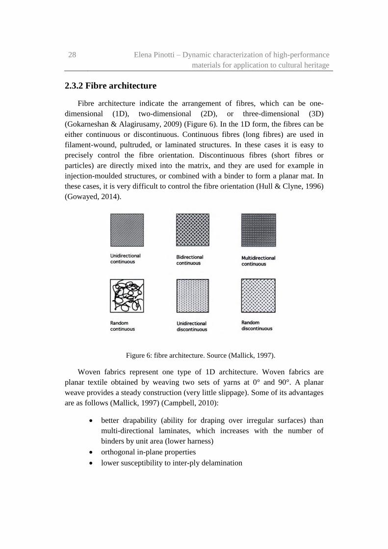
28 Elena Pinotti – Dynamic characterization of high-performance
materials for application to cultural heritage
2.3.2 Fibre architecture
Fibre architecture indicate the arrangement of fibres, which can be one-
dimensional (1D), two-dimensional (2D), or three-dimensional (3D)
(Gokarneshan & Alagirusamy, 2009) (Figure 6). In the 1D form, the fibres can be
either continuous or discontinuous. Continuous fibres (long fibres) are used in
filament-wound, pultruded, or laminated structures. In these cases it is easy to
precisely control the fibre orientation. Discontinuous fibres (short fibres or
particles) are directly mixed into the matrix, and they are used for example in
injection-moulded structures, or combined with a binder to form a planar mat. In
these cases, it is very difficult to control the fibre orientation (Hull & Clyne, 1996)
(Gowayed, 2014).
Figure 6: fibre architecture. Source (Mallick, 1997).
Woven fabrics represent one type of 1D architecture. Woven fabrics are
planar textile obtained by weaving two sets of yarns at 0° and 90°. A planar
weave provides a steady construction (very little slippage). Some of its advantages
are as follows (Mallick, 1997) (Campbell, 2010):
better drapability (ability for draping over irregular surfaces) than
multi-directional laminates, which increases with the number of
binders by unit area (lower harness)
orthogonal in-plane properties
lower susceptibility to inter-ply delamination

High performance materials 29
larger design envelope (hybrid textiles, different fibre volume fraction
in warp and weft directions, fabric type).
Disadvantages are the following:
lower stiffness and strength (due to crimp) than multi-directional
laminates
higher processing costs than unidirectional laminates.
Two and three-dimensional architectures are produced by means of textile
processes such as interlacing, intertwining, and interloping continuous fibres in
textile machines. The textile is produced realised in mesh form with well-defined
cell dimensions, which can be protected by a bituminous coat. It provides a good
geometric stability, and works as a protective layer against a damaging agents
(Gowayed, 2014).
Two-dimensional and three-dimensional products are knitted fabrics, braded
fabrics, random mats, 3D woven fabrics, and non crimp-fabrics (Campbell, 2010)
(Hollaway, 1993).
In detail:
knitted fabrics are planar textile performs obtained by interloping one
set of yarns (drawing loops of one yarn in the previous one, for
example). Straight warp and/or filling yarns can be added to increase
stiffness.
Braided fabrics are textile pre-forms obtained by interlacing yarns in
the bias direction. They are similar to rotated woven fabrics. Braded
fabrics combine high torsional stiffness with large deformability in
tension (Figure 7).
Random mats are materials manufactured from a set of disordered
fibres made by bonds of different nature such as simple entanglement,
local thermal fusion or chemical binders. They are cheaper than their
textile counterparts and have a lower strength and stiffness but higher
deformability (Figure 8).

30 Elena Pinotti – Dynamic characterization of high-performance
materials for application to cultural heritage
Figure 7: braided fabrics. Source (Nivitex.Fibreglass.and.Resins, 2017) and
(Composites, 2014).
Figure 8: disordered glass fibres and random mat. Source (CNR-DT 200/2004,
2004).
3D woven fabrics are manufactured to improve the strength and the
stiffness of textile pre-forms in the direction perpendicular to the
fabric.
Non crimp-fabrics are multidirectional laminates made up of
unidirectional plies with different fibre orientation that are assembled
and stitched together. In-plane mechanical properties are enhanced by
the absence of crimp. Inter-ply delamination is inhibited by the 3D
stitching.
Long textile fibres in composite materials of continuous length and usually 5-
25μm in diameter are relatively stiff and strong. Their role is to absorb the tensile
forces, mainly those parallel to their direction. Long textile fibre are characterise
by high tensile strength, high length/diameter ratio, and by high ratio of strength
to weight. Their mechanical behaviour is strictly related to some design
parameters such as fibre angle, mesh size, wrap direction, etc.
High performance materials 31
Textile processes provide a good control over the fibre orientation, as well as
fibre placement, and can be used to produce a variety of complex shapes or forms
in a relatively short time. Two-dimensional architecture is used in laminated
structures. A three-dimensional arrangement of continuous fibres is used when
interlaminar failure or delamination becomes a problem with laminated structures
that are made by stacking several laminae on top of one another. Laminated
structures contain no fibres in the thickness direction and often fail by separation
of laminae. Three-dimensional architecture can also be used to build composites
with equal properties in the x, y, and z directions.
The fibre placement into a composite lamina can be unidirectional,
bidirectional, multidirectional, or random. In the case of unidirectional placement
of continuous fibres, the fibres are most efficient when the load in the composite
is applied long the fibre direction (longitudinal direction). The strength and
modulus of a unidirectional lamina are the highest in the direction of fibres and
are much lower in other directions, particularly in the transverse direction (normal
to the fibre). The matrix controls the properties perpendicular to the fibres.
A multidirectional laminates are built by stacking unidirectional lamina with
different orientations. This placement is useful to reduce the variation of
properties in different directions. Instead, when the fibres are randomly oriented,
equal properties are obtained in all directions in the lamina plane. Consequently,
the result of a randomly oriented arrangement of fibres is a quasi-isotropic lamina.
The lamina properties will be much lower respect to the fibre direction properties
of a unidirectional lamina.
2.4 High performance materials: matrix
The matrix is the continuous phase in a composite material, and it plays
several important uses as follows (Holloway, 2003) (Campbell, 2010) (CNR-DT
200/2004, 2004):
prevents the reinforcement from moving
makes possible the transfer of stress between fibres (when composite
is under load)
protects the reinforcements from harsh environment, damage during
handling, and during the service life of the composite.
32 Elena Pinotti – Dynamic characterization of high-performance
materials for application to cultural heritage
The matrix should disperse the fibres and separate them in order to avoid any
catastrophic propagation of crack leading to failure of the composite, and finally
to be chemically and thermally compatible with fibres over a long period.
The matrix plays only a minor role in the longitudinal tensile properties of a
unidirectional continuous fibre composite while it is important in the transverse
direction. The matrix selection influences some properties of a unidirectional fibre
composite: the transverse tensile modulus and strength, longitudinal and
transverse compressive properties and, shear modulus and strength. Moreover, it
is important to highlight that for evaluating the mechanical properties of a
composite material, the matrix has a great effect on its processing characteristics
(Niroumand, 2009).
Matrix materials can be metallic, ceramic or polymeric. Polymeric materials
are most widely used to produce composites as they are easy to infiltrate in the
fibre perform, and are cheap when compared to other materials. Polymeric
materials can be thermosets (resins) or thermoplastics.
Thermosets are polymers with branched chains. They are formed in situ by a
chemical reaction (curing) between two polymers (resin-hardener or resin-
catalyst), leading to three-dimensional network in which covalent bonds link
different polymeric chains. Once cured, they do not become liquid again if heated,
even if their mechanical properties decrease significantly over the glass transition
temperature (Tg). The molecular structure over Tg changes from a rigid to
flexible network. This change is reversible. Thermoset polymers are low viscosity
liquids at room temperature. They have high stiffness and strength, and good
resistance to chemical attacks. Their main limitations are their brittleness and
limited high-temperature capabilities (especially under hot/wet conditions)
(Hollaway, 2010).
The most widespread thermoset polymers are:
Polyester resins
Vinylester resins
Epoxy resins
Phenolic resins
Bismaleimides resins (BMI)
Polymides resins.

High performance materials 33
Polyester resins are the most widely used matrices because of their low cost,
good process ability, and environmental resistance. Particularly popular in marine
industry are used in all applications that do not require extreme properties. Most
polyester resins are viscous liquids consisting of a solution of a polyester in
styrene. The addition of styrene (up to 50%) reduces the viscosity and enables
resin curing by cross-linking of the polyester molecular chains.
The most common matrix used for FRP is an organic resin-based matrix. For
structural engineering applications, polyester, vinylester, and epoxy are the widely
used organic matrices. Epoxy matrix is widely used mainly because of its
excellent adhesion to the fibres (due to its low viscosity), and due to the low
amount of shrinkage during the curing process. It is important to notice that epoxy
matrices have high-level of hardness, high-resistance to humidity and fatigue. It is
possible to see that, after the curing period, a typical epoxy matrix has higher
strength and stiffness properties than a polyester and vinylester matrix.
Thermoplastic polymers can have an amorphous or semi-crystalline structure.
They alternate crystalline regions with amorphous ones in which the chains are
approximate random coils. Thermoplastic polymers usually possess higher
ductility and toughness when compared to thermoset polymers below glass
transition temperature. Both properties increase very rapidly above Tg while the
strength decreases. After the glass transition temperature, the amorphous chains
change from glassy to a rubbery phase. Over melting temperature (Tm), the
viscosity gradually decreases without any distinct phase change, and
thermoplastic polymers become viscous liquids that can be easily infiltrated into
fibre performs. They can go through melting/freezing cycles repeatedly and can
be re-melted and remoulded.
The most widely used thermoplastic polymers are (Das & Nizam, 2014):
Polyolefins (PE, PP)
Polyamides (Nylon)
Polystirene
Polyphenylene Sulphide (PPS)
Polyetherethererketone (PEEK)
2.5 Why choose a high performance material
Composites materials, especially FRP composites, offer many advantages
compared to traditional materials for engineering applications (Karbhari & Zhao,

34 Elena Pinotti – Dynamic characterization of high-performance
materials for application to cultural heritage
2000). The main advantage is that they are light as well as strong. Another
significant advantage is that, by choosing an appropriate mix of matrix and
reinforcement material, a new material can be made. Thus composite materials
can precisely meet the requirements of a particular application and thus provide
design flexibility. They can also be moulded into complex shapes.
Composite materials are perfect substitutes for steel, aluminium, titanium and
other metals and are typically preferred because of their following properties
(Niroumand, 2009) (Das & Nizam, 2014) (CNR-DT 200/2004, 2004):
High-strength: FRP composites are very effective in enhancing strength.
They can be designed to provide a specific range of mechanical properties like
tensile, flexural, impact and compressive strengths.
However, there are different kind of fibres commercially available, which
different properties. For example, the aramid fibres have relatively low
compressive strength compared to carbon fibre.
Lightweight: FRP composites have a higher specific strength compared to
most materials used in similar applications. They can show more strength per
weight than most metal alloys.
High-strength to weight ratio: the strength of a material is the force per unit
area at failure per unit density. Any material that is strong and light has a higher
strength/weight ratio. Materials such as aluminium, titanium, magnesium, carbon
and glass fibre, and high-strength steel alloys all have good strength to weight
ratios.
Rigidity: rigidity or stiffness of a material is measured in terms of Young’s
Modulus, and represents the deflection of a material under stress. Carbon fibre
reinforced plastic is over 4 times stiffer than glass reinforced plastic (Figure 9).
Tensile strength: tensile strength or ultimate strength is the maximum stress
that a material can withstand while being stretched. High performance fibre
materials used in FRP are characterized by high tensile strength. However, brittle
materials such as carbon fibre does not always fail at the same stress level because
of internal flaws. Tensile strength of aramid fibres is slightly less than E-glass
fibre (Hollaway & Head, 2001).
Fatigue Resistance: reduction in stiffness with large number of stress cycles
is called fatigue which can lead to failure (unless the temperature is high).

High performance materials 35
Test have shown that failure is unlikely to be a problem when cyclic stresses
acts in the direction of fibres. Carbon FRP (CFRP) is superior to glass FRP
(GFRP) in fatigue and static strength and stiffness. But when CFRP fails, it will
not show any significant exterior signs and thus the failure will be catastrophic.
The orientation of individual fibres and the fibre layer have a significant
influence on the fatigue resistance. Different types of forces results in different
failure modes.
Figure 9: stress-strain curve of the main high-performance materials. Source (CNR-
DT 200/2004, 2004).
Impact and explosive loading: the behaviour of FRP systems when
subjected to impact or explosive loading is not yet completely understood.
However, it is seen that aramid FRP (AFRP) are more resistant to impact than the
CFRP.
Mechanical properties such as tensile strength, ultimate strain, and Elastic
modulus of FRP systems degrade under aggressive conditions such as alkaline
environment, moisture, extreme temperatures, thermal cycles, freeze and thaw
cycles, and ultraviolet radiations (UV) (Karbhari, 2007).
Effects of alkaline environment: the water contained in the pores of concrete
(or masonry) could cause deterioration of the resin and/or the interface between
36 Elena Pinotti – Dynamic characterization of high-performance
materials for application to cultural heritage
FRP and the support. The damage caused by exposure to alkaline environment is
typically more dangerous when compared to moisture exposure. The resins have
to be completely cured before being exposed to an alkaline environment.
Effects of moisture: the main effects of moisture absorption are plasticization
and reduction of glass transition temperature, strength and stiffness. The moisture
absorption depends on the resin type, composition and quality of the laminate,
thickness, curing conditions, resin-fibre interface, and finally the working
conditions.
Effects of temperatures variation and thermal cycles: the viscous response
of the resin and the composite depends on the temperature. With increase in
temperature the modulus of elasticity of the resin decreases. The performance of
FRP materials significantly decreases when the temperature is above Tg. Thermal
cycles do not have harmful effects on FRP composites. However they can cause
micro-fractures in systems in which resins of high modulus of elasticity is used.
In civil infrastructure applications, undesired performance may be avoided by
choosing a system in which the Tg is always higher than the maximum operating
temperature of the structure or component that is strengthened.
Effects of freeze and thaw cycles: exposure to freeze and thaw cycles does
not have an impact on FRP performance, but reduces the performance of the resin
and the fibre-resin interface. Polymer based resin systems can be improved, by
providing higher strength and stiffness for temperatures lower than 0 °C. The
effects of the decay induced in these cases, could be amplified by the presence of
moisture.
Effects of ultraviolet radiation (UV): UV rays rarely deteriorate the
mechanical performance of a systems strengthened with FRP. The most harmful
effect related to UV exposure is the penetration of moisture and other aggressive
agents through the damaged surface. Systems reinforced with FRP, could be
protected from such damages by adding fillers to the resin or by providing
appropriate coatings. AFRP will degrade particularly if exposed to sunlight and in
high UV environment. Thus it is necessary to apply protective coatings to avoid
the material degradation. Similarly epoxy resin is sensitive to UV ray and thus
needs to be protected while carbon fibres will not deteriorate easily. This problem
could involve other matrices.

High performance materials 37
The great sensitivity of Kevlar fibres to UV rays is a topic discussed in
Chapter 6 of this work.
Mechanical properties such as tensile strength, ultimate strain, and elasticity
modulus of systems strengthened with FRP, can also degrade due to creep,
relaxation, and fatigue.
Effects due to creep and relaxation: both creep and relaxation depends in
the properties of resins and fibres. Thermosetting resins are less viscous than
thermoplastic resins. This phenomena is evident when the load is applied
transverse to the fibres or when the composite has a low volume ratio of fibres,
because the presence of fibres decrease the resin creep. Creep phenomena can be
reduced ensuring low serviceability stresses. FRP systems made of carbon, aramid
(e.g. Kevlar), and glass are the least, moderately, and most prone to creep rupture,
respectively (Scott, et al., 1995).
Fatigue effects: the performance of FRP systems under fatigue conditions
depends on the matrix composition and, on the fibre type. In the case of
unidirectional composites, the fibres usually have some defects. This can delay
the formation of cracks. They are also prevented by the action of adjacent fibres.
Other properties of composite materials which are useful for structural
applications are the following:
Corrosion Resistance: FRP composites do not rust or corrode. If properly
designed, the FRP composite components can have long service life and minimum
maintenance when compared to traditional building materials. AFRP is not
sensitive to organic solvents or oil, but are sensitive to strong acids, bases, and
certain oxidizers. Exposure to these chemical substances could cause degradation
of the fibres (Sen, 2003).
Durability: FRP composite technology is “new” compared with materials
that it often replaces, such as concrete, masonry, steel or wood. Hence, many
composite components have not yet attained their full life span. There are also
some structures like FRP composite boats, tanks and certain other products that
are in use for more than 50 years (CompositeBuild.com, 2014) (Karbhari, et al.,
2003).

38 Elena Pinotti – Dynamic characterization of high-performance
materials for application to cultural heritage
Design Flexibility: FRP composites can be fabricated into any kind of
complex shape and configuration which can be large or small and can be used for
structural, decorative or their combination. Composites materials do not bind the
designers for any way, from prototype to production, based on the needs. Due to
the design and fabrication flexibility of composites materials, single composite
parts could replace complex assembly units of multiple parts that are produced
with traditional materials such as wood, masonry, steel or aluminium. This
property is very useful for applications on cultural heritage structures.
Dimensional Stability: FRP composite materials maintain their form and
functionality with severe mechanical and environmental stresses.
Good resistance to abrasion and cutting: AFRP is often used for protection
against cutting. Aramid materials are used worldwide for making armour and
bullet proof materials, gloves, etc. which protect against sharp materials in
construction industry (Bin Kabir & Ferdous, 2012).
Strengthening limitation in case of fire: composite materials are very
sensitive to high-temperatures that can happen during a fire. When the
temperature exceeds Tg of the resin (or the Tm in semi-crystalline materials),
strength and stiffness of the FRP system are considerably reduced. While, in case
of FRP used as external reinforcement for concrete or masonry structures, the
exposure to high-temperature results in higher degradation of the bond between
the composite system and the support (Katz, et al., 1999).
Composite parts can also be fabricated using appropriate polymer binder and
filler technology for providing better performances for high-temperature
applications. Using suitable manufacturing process and precursor materials,
suitable carbon fibre composites can be designed to be used as protective clothing
for firefighting (Keller, et al., 2006). As carbon fibres are chemically inert, they
can also be used where the fire causes the release of corrosive agents. But these
materials are costly. The resulting product is more efficient, but the raw materials
are often expensive (Benichou, et al., 2010).
Low Thermal Conductivity: FRP composites are naturally poor conductors.
But, thermally or electrically conductive materials can be incorporated into the
composite part if high thermal or electrical conductivity is required. Thermal
conductivity is a measure of how easily heat flows through a material.
High performance materials 39
Carbon fibres have high thermal conductivity in some forms. Since there are
many variations on the theme of carbon fibre, is not possible to identify exactly
the thermal conductivity of the material. Some varieties of carbon fibres could be
specifically designed for high or low thermal conductivity.
Low coefficient of thermal expansion: This is a quantitative measure of
expansion and contraction of a material with rise and fall in temperature.
Low coefficient of thermal expansion makes CFRP suitable for applications
where small movements can be critical such as for telescope and optical
machinery.
Electrical conductivity: This is a critical property which has both merits and
demerits. Carbon fibre conductivity can facilitate galvanic corrosion in fittings. A
careful installation of the device may reduce the problem related to electrical
conductivity.
Moreover, CFRP dust can accumulate and cause sparks or short circuits in
electrical appliances and equipment.
High Dielectric Strength: FRP composites have excellent electrical
insulating properties, making them an obvious choice for components in current
carrying applications.
Vandalism: FRP composite materials are particularly sensitive to cuts and
incisions produced by cutting tools. Hence, for protection of critical structures
which may be subjected to vandalism adequate strengthening can be provided.
2.6 Commonly used fibres for structural applications
The most common type of fibres used for structural applications are the glass,
carbon and aramid fibres. FRP are most attractive because they are cost-effective
for their improved durability, the life-cycle maintenance costs are reduced, and
they are easier for transporting and improving on-site productivity (CNR-DT
200/2004, 2004) (Christensen, et al., 1996) (Das & Nizam, 2014).
2.6.1 Glass fibres
Transforming glass into fibres is an ancient art. From the ancient times, these
fibres were used to reinforce clay vessels and statues. Glass fibres are among the
most versatile industrial materials known today (Wallenberger, et al., 2001).
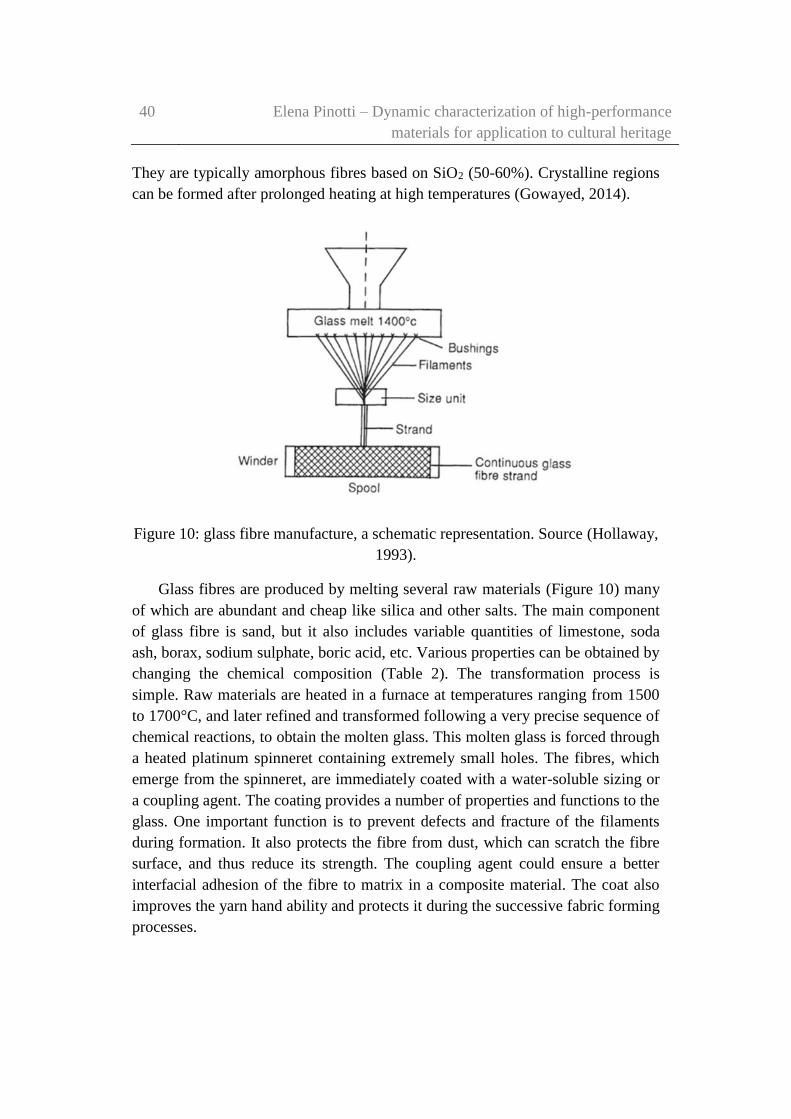
40 Elena Pinotti – Dynamic characterization of high-performance
materials for application to cultural heritage
They are typically amorphous fibres based on SiO2 (50-60%). Crystalline regions
can be formed after prolonged heating at high temperatures (Gowayed, 2014).
Figure 10: glass fibre manufacture, a schematic representation. Source (Hollaway,
1993).
Glass fibres are produced by melting several raw materials (Figure 10) many
of which are abundant and cheap like silica and other salts. The main component
of glass fibre is sand, but it also includes variable quantities of limestone, soda
ash, borax, sodium sulphate, boric acid, etc. Various properties can be obtained by
changing the chemical composition (Table 2). The transformation process is
simple. Raw materials are heated in a furnace at temperatures ranging from 1500
to 1700°C, and later refined and transformed following a very precise sequence of
chemical reactions, to obtain the molten glass. This molten glass is forced through
a heated platinum spinneret containing extremely small holes. The fibres, which
emerge from the spinneret, are immediately coated with a water-soluble sizing or
a coupling agent. The coating provides a number of properties and functions to the
glass. One important function is to prevent defects and fracture of the filaments
during formation. It also protects the fibre from dust, which can scratch the fibre
surface, and thus reduce its strength. The coupling agent could ensure a better
interfacial adhesion of the fibre to matrix in a composite material. The coat also
improves the yarn hand ability and protects it during the successive fabric forming
processes.
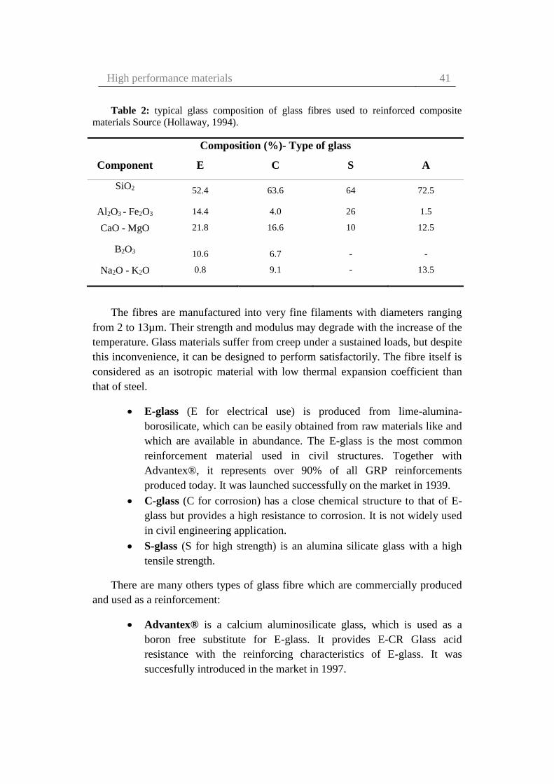
High performance materials 41
Table 2: typical glass composition of glass fibres used to reinforced composite
materials Source (Hollaway, 1994).
Composition (%)- Type of glass
Component E C S A
SiO2 52.4 63.6 64 72.5
Al2O3 - Fe2O3 14.4 4.0 26 1.5
CaO - MgO 21.8 16.6 10 12.5
B2O3 10.6 6.7 - -
Na2O - K2O 0.8 9.1 - 13.5
The fibres are manufactured into very fine filaments with diameters ranging
from 2 to 13µm. Their strength and modulus may degrade with the increase of the
temperature. Glass materials suffer from creep under a sustained loads, but despite
this inconvenience, it can be designed to perform satisfactorily. The fibre itself is
considered as an isotropic material with low thermal expansion coefficient than
that of steel.
E-glass (E for electrical use) is produced from lime-alumina-
borosilicate, which can be easily obtained from raw materials like and
which are available in abundance. The E-glass is the most common
reinforcement material used in civil structures. Together with
Advantex®, it represents over 90% of all GRP reinforcements
produced today. It was launched successfully on the market in 1939.
C-glass (C for corrosion) has a close chemical structure to that of E-
glass but provides a high resistance to corrosion. It is not widely used
in civil engineering application.
S-glass (S for high strength) is an alumina silicate glass with a high
tensile strength.
There are many others types of glass fibre which are commercially produced
and used as a reinforcement:
Advantex® is a calcium aluminosilicate glass, which is used as a
boron free substitute for E-glass. It provides E-CR Glass acid
resistance with the reinforcing characteristics of E-glass. It was
succesfully introduced in the market in 1997.

42 Elena Pinotti – Dynamic characterization of high-performance
materials for application to cultural heritage
AR-Glass (Alkali resistant glass) is composed of alkali zirconium
silicates. It was developed for use in concrete. It is mainly used for
GRC (Glass Reinforced Cement) roofing, and sheeting panels.
D-glass (Borosilicate glass) is characterized by a low dielectric
constant. It is used for special applications requiring permeability to
electromagnetic waves.
E-CR Glass (Calcium aluminosilicate glass) is produced with a high
alkali content. It is used where high acid corrosion resistivity is needed
in addition to strength and electrical resistivity. It is commercially
available since 1980.
R-glass (Calcium aluminosilicate glass) is characterised by higher
strength and temperature resistance when compared to E-CR Glass or
Advantex®.
Glass fibres typically used to reinforce composite materials are divided into
three main classes and is shown in Table 3 (Kinsella, et al., 2001).
The basic structure of glass fibre is composed of tetrahedral structural unit of
silica (SiO4) (Figure 11). The silica atom forms a tetrahedral shape with four
oxygen atoms.
Table 3: Mechanical properties of some glass fibres. Source (Kinsella, et al.,
2001).
Tensile
Modulus
Tensile
strength
Poisson’s
ratio Density
Strain to
failure
[GPa] [GPa] [g/cm3] [%]
E - Glass 72 3.45 0.22 2.55 1.8-3.2
C - Glass 69 3.3 - 2.49 -
S - Glass 87 3.5 0.23 2.5 4
The presence of calcium (Ca), sodium (Na), and potassium (K) breaks the
silica network, reducing the stiffness and strength of the fibre. This improve the
formability of the melt to form the fibres (Gowayed, 2014).
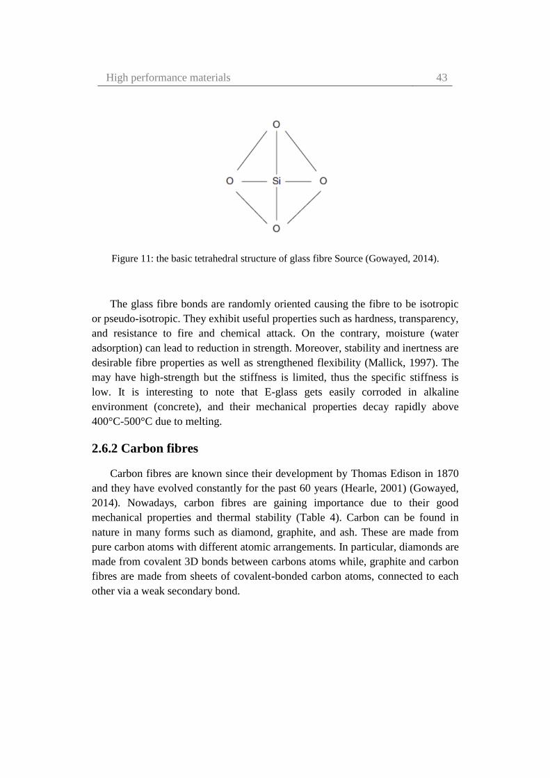
High performance materials 43
Figure 11: the basic tetrahedral structure of glass fibre Source (Gowayed, 2014).
The glass fibre bonds are randomly oriented causing the fibre to be isotropic
or pseudo-isotropic. They exhibit useful properties such as hardness, transparency,
and resistance to fire and chemical attack. On the contrary, moisture (water
adsorption) can lead to reduction in strength. Moreover, stability and inertness are
desirable fibre properties as well as strengthened flexibility (Mallick, 1997). The
may have high-strength but the stiffness is limited, thus the specific stiffness is
low. It is interesting to note that E-glass gets easily corroded in alkaline
environment (concrete), and their mechanical properties decay rapidly above
400°C-500°C due to melting.
2.6.2 Carbon fibres
Carbon fibres are known since their development by Thomas Edison in 1870
and they have evolved constantly for the past 60 years (Hearle, 2001) (Gowayed,
2014). Nowadays, carbon fibres are gaining importance due to their good
mechanical properties and thermal stability (Table 4). Carbon can be found in
nature in many forms such as diamond, graphite, and ash. These are made from
pure carbon atoms with different atomic arrangements. In particular, diamonds are
made from covalent 3D bonds between carbons atoms while, graphite and carbon
fibres are made from sheets of covalent-bonded carbon atoms, connected to each
other via a weak secondary bond.

44 Elena Pinotti – Dynamic characterization of high-performance
materials for application to cultural heritage
Table 4: mechanical properties of some carbon fibres. Source (Hearle, 2001).
Precursor
type
Product
name
Young’s
modulus
Tensile
strength
Strain to
failure
[GPa] [GPa] [%]
PAN T300 230 3.53 1.5
T1000 294 7.06 2.0
M55J 540 3.92 0.7
IM7 276 5.30 1.8
Pitch KCF200 42 0.85 2.1
Thornel P25 140 1.40 1.0
Thornel P75 500 2.00 0.4
Thornel P120 820 2.20 0.2
Carbon fibres can be manufactured by controlled pyrolysis and cyclization of
certain organic fibre precursors. It can be made from three types of polymer
precursors: polyacrylonitrile (PAN) fibre, rayon fibre, and precursor mesophase
pitch (MPP). The first is a synthetic fibre while, the third is produced from the
destructive distillation of coal. It is interesting to note that rayon was one of the
first precursors used to make carbon fibres. But during this conversion only 25%
of the fibre mass is maintained and thus carbon fibres manufactured from Rayon
precursors are very expensive (Hollaway, 1993) (Chand, 2000).
Another precursor named Polyacrylontrile (PAN) fibre, is more economical
with a conversion yield of around 50–55%. Moreover, carbon fibres made from a
PAN precursor generally have higher strength when compared to fibres made
from other precursors (Niroumand, 2009). This is due to the lack of surface
defects, which act as stress concentrators, thereby reducing tensile strength.
Another commonly used precursor is the Pitch precursor, which is a product of
petroleum refining. But because of the irregular surfaces of the fibre, their tensile
and compressive strengths are reduced (Hearle, 2001). Nowadays, carbon fibres
are made from both a PAN and a Pitch precursor, while rayon precursors are used
in less than 1% of the carbon fibres production (MIL-HDBK-17-5, 2002)
(Gowayed, 2014).

High performance materials 45
There are several processes for converting a PAN precursor into a carbon
fibre. The precursor-to-carbon-fibre conversion process consists of a sequence of
procedures (show in Figure 12):
Stabilization
carbonization
graphitization
surface treatment
application of sizing and spooling.
Figure 12: Manufacturing process of carbon fibre. Source (Hollaway, 1993).
Stabilization is performed at temperatures < 400°C in various atmospheres to
reach a dimensional stability. This phase is called the infusible step. During this
step, the fibre is held under tension to improve molecular orientation, which
increases fibre modulus and strength. Carbonization is carried out at temperatures
from 800 to 1200°C in an inert atmosphere. The fibre is held under tension also
during this process. In this step, polymer backbones are converted at higher
temperature into ribbons of continuous carbon hexagonal rings. During the
heating period, majority of elements other than carbon are removed and carbon
crystallites are preferably orientated along the fibre length. Graphitization is an
additional process and is performed at temperatures higher than 2000°C in an inert
environment. In this process, the level of impurities decrease, the size of the
carbon crystallites and the orientation of the fibre crystallites improves. Finally,
the fibre passes through the surface treatment chamber to incentivise fibre
adhesion. The crystalline size, crystal orientation, fibre porosity and impurity are
major factors influencing the final physical properties of the filament. During the
surface treatment process, various materials can be applied to the surface of
46 Elena Pinotti – Dynamic characterization of high-performance
materials for application to cultural heritage
carbonized/graphitized fibre. These materials will control the interaction between
the fibres and the matrix in composite materials. The coating is applied to fibre
yarns to improve their handling characteristics in further textile forming
operations. At the end, the fibre is spooled on a carrier tube to form a stable
package.
Carbon fibre filaments are made typically with a diameter ranging from 5 to 8
µm, and are combined into tows containing 5000 and 12000 filaments. The tows
can be twisted into yarns and woven into fabrics. Hybrid fabrics, are also
commercially available which contain either glass and carbon fibres (or aramid
and carbon fibres).
Carbon fibres are characterized by low thermal expansion coefficients with
respect to both glass and aramid fibres. Carbon fibre is an anisotropic material. Its
transverse modulus are lower by an order of magnitude when compared to its
longitudinal modulus. Carbon fibre material has very high fatigue and creep
resistance. Its tensile strength decreases with increasing modulus, and thus its
strain at rupture will also be much lower. As, this material is brittle, it should be
carefully used in joints and connections which are places of high-stress
concentration.
The modulus of elasticity of carbon fibres rises exponentially throughout the
temperature range during heat treatment, as shown in Figure 13.
This is due to the increase in the crystallinity of the fibre which leads to a
decrease in the amorphous characters. On the contrary, tensile strength increases
in value to a maximum at about 1600°C and then falls to a constant value with
further increase in value. Three distinct types of carbon fibres have been identified
from the heat treatment temperatures. They can be classified as:
Type 1: the stiffest carbon fibre, and thus requires the highest heat
treatment temperature.
Type 2: the strongest carbon fibre, and thus has been carbonised at the
temperature that gives the greatest tensile strength.
Type 3: the cheapest carbon fibre. The stiffness is lower than the
previous types but has good strength. This type requires the lowest
heat treatment temperature.

High performance materials 47
Figure 13: effect of heat treatment temperature compared to tensile strength and modulus
of elasticity. Source (Campbell, 2010).
Carbon fibres are currently used for aerospace and space applications. They are
also being considered for use in the construction sector. Its cost is comparable to
glass fibre. Carbon fibres may be used together with a polymer or a cement
matrix.
2.6.3 Aramid fibres
Aramid fibres are synthetic organic fibres in the aromatic polyamide family,
which have a high-degree of crystallinity. They are distinguished from other
commercial man-made synthetic fibres by their organic chemical composition of
fully aromatic polyamides (aramids). The molecular chains are aligned and made
rigid by means of aromatic rings linked by hydrogen bridges (Gowayed, 2014).
This combination explains their very high strength. Their chemical structure is
indicated in Figure 14.
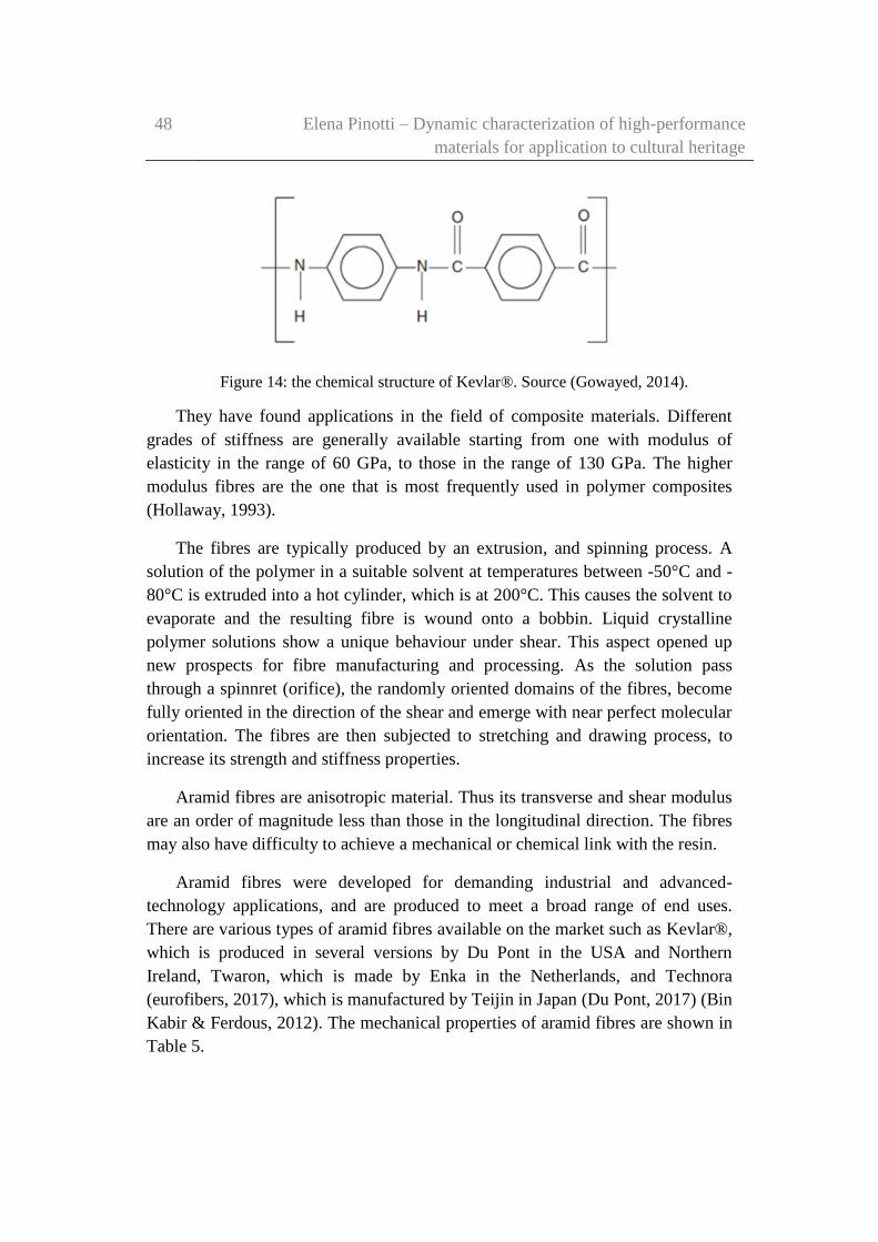
48 Elena Pinotti – Dynamic characterization of high-performance
materials for application to cultural heritage
Figure 14: the chemical structure of Kevlar®. Source (Gowayed, 2014).
They have found applications in the field of composite materials. Different
grades of stiffness are generally available starting from one with modulus of
elasticity in the range of 60 GPa, to those in the range of 130 GPa. The higher
modulus fibres are the one that is most frequently used in polymer composites
(Hollaway, 1993).
The fibres are typically produced by an extrusion, and spinning process. A
solution of the polymer in a suitable solvent at temperatures between -50°C and -
80°C is extruded into a hot cylinder, which is at 200°C. This causes the solvent to
evaporate and the resulting fibre is wound onto a bobbin. Liquid crystalline
polymer solutions show a unique behaviour under shear. This aspect opened up
new prospects for fibre manufacturing and processing. As the solution pass
through a spinnret (orifice), the randomly oriented domains of the fibres, become
fully oriented in the direction of the shear and emerge with near perfect molecular
orientation. The fibres are then subjected to stretching and drawing process, to
increase its strength and stiffness properties.
Aramid fibres are anisotropic material. Thus its transverse and shear modulus
are an order of magnitude less than those in the longitudinal direction. The fibres
may also have difficulty to achieve a mechanical or chemical link with the resin.
Aramid fibres were developed for demanding industrial and advanced-
technology applications, and are produced to meet a broad range of end uses.
There are various types of aramid fibres available on the market such as Kevlar®,
which is produced in several versions by Du Pont in the USA and Northern
Ireland, Twaron, which is made by Enka in the Netherlands, and Technora
(eurofibers, 2017), which is manufactured by Teijin in Japan (Du Pont, 2017) (Bin
Kabir & Ferdous, 2012). The mechanical properties of aramid fibres are shown in
Table 5.

High performance materials 49
Table 5: mechanical properties of some carbon fibres. Source (Gowayed, 2014).
KEVLAR®29 KEVLAR®49
Tensile modulus [GPa] 70.5 112.4
Poisson’s ratio - 0.36
Strength [GPa] 2.92 3
Strain to failure [%] 3.6 2.4
Density [g/cm3] 1.44 1.44
Thermal conductivity [W/m°K] 0.04 0.04
Coefficient of thermal expansion [x10-6/°K] -4 -4.9
In Table 6 an overview on the main mechanical properties of glass, carbon,
and aramid fibres is shown.
Table 6: typical mechanical properties for glass, aramid, and carbon fibres. Source
(Hollaway, 1993).
Material Fibre Elastic
modulus
Tensile
strength
Ultimate
strain
Density Max
temperature
[GPa] [MPa] [%] [g/cm2] [°C]
Glass E 72.4 2400 3.5 2.55 250
A 72.4 3030 3.5 2.50 250
S-2 88.0 4600 5.7 2.47 250
Aramid 49 125 2760 2.4 1.44 180
29 83 2750 4.0 1.44 180
Teijin Technora 70 3000 4.4 1.39 -
Carbon XAS HS 235 3800 1.64 1.79 600
Grafil HS 235 3450 1.64 1.79 600
IM-S 290 3100 1.64 1.76 600
HM-S6K 370 2750 1.64 1.86 600
Toray T-300 230 3530 1.5 1.77 600
M-46-J 450 4100 2.4 1.82 600

50 Elena Pinotti – Dynamic characterization of high-performance
materials for application to cultural heritage
2.7 Brief history of polymers and composites used in
construction industry
Bakelite was the first synthetic polymer and was first made in 1909. This
material takes its name from its inventor Leo Baekeland who was an American
chemist. From a chemical perspective Bakelite is a phenol formaldehyde resin
produced when phenol (carbolic acid) and the gas formaldehyde are combined in
the presence of a catalyst. If the reaction is allowed to proceed to completion, a
dark brown substance of little use is produced. Baekeland discovered that, if the
reaction is controlled by closing it before completion a material can be created
which could flow and hence could poured into moulds. If these were then heated
and when appropriate pressure is applied a heavy solid plastic material is formed.
This material is used nowadays in specific engineering applications. From this
innovative invention, it is now possible to adapt polymers and to create new ones
that can be designed for specific use (Holloway, 2003).
The history of the use of polymers and composites in the construction
industry began during the Second World War, when rapid progress was made
with the manufacture of the first radomes to house electronic radar equipment.
Many aircraft components in this period, were also made using GFRP (Holloway,
2003).
It is possible to divide the history of composite materials into four different
generation (Rawal, 2001) (Srivastava & Hoda, 2016).
2.7.1 First generation (1930s-1940s)
The first generation was dedicated on Glass Fibre Reinforced Composites.
While solid-state scientists focused on the relation between structure and
properties, industrial researchers were more concerned on the relations between
functions and properties.
In 1932, Owens in the USA started the production of glass fibres. In 1935,
they merged with Corning to form Owens-Corning Fibres with the sole purpose of
starting a mass production of these fibres (OwensCorning, 1999). In 1939, in
Europe Balzaretti Modigliani (Italy) obtained the rights for the Owens’ patent, and
transferred them to Saint-Gobain. At the same time, chemical companies were
conducting research on new polymers. Phenolic, urea, and aniline-formaldehyde

High performance materials 51
resins were developed in the early 1930s, together with the unsaturated polyester
resins patented in 1936 which then dominated the field of composites. In 1938, P.
Castan (in Switzerland) received the first patent for epoxy resins, and soon
authorised the patent to Ciba.
The mix of polymers with various additives (for example with chargers,
fillers, and plasticity agents) were already a tradition in chemical industries.
The increasing importance of these innovative materials (polymers) in
industry was evident with the establishment of the Society of the Plastics Industry
in 1937 (Council®, 2012-2017), followed by the Society of Plastics Engineers in
1941 (Schulman, 2017). The creation of these scientific societies, showed an
increasing interest on a topic that connects people from different universities and
companies to exchange information about the latest discoveries (Figure 15).
Figure 15: Schematic diagram showing the relative importance of ceramics,
composites, polymers and metals, in mechanical and civil engineering as a function of
time (The time scale is nonlinear). Source: (Ashby, 1987).
In 1940s, technicians and engineers had to find a best solution to add fibres to
the system. The problem was that the fibres should be distributed throughout the
matrix and should not be clustered together. The initial trials consisted in applying
a high-pressure to the early resins and to allow them to cure. But, this resulted in

52 Elena Pinotti – Dynamic characterization of high-performance
materials for application to cultural heritage
some problems. The high-pressure easily damaged the glass fibres. To solve this
problem, in 1940, Pittsburgh Plate Glass developed low-pressure allyl polyester
resins, and in 1942, Marco Chemical Company in Linden (New Jersey), was hired
to investigate other similar low-pressure curing resins. In the same year, the first
fiberglass laminates made from PPG CR-38 and CR-39 resins were produced
(Rosato, 1982).
The earliest applications of GFRP products were in the marine industry
(Selvaraju & Ilaiyave, 2011). In the early 1940s, GFRP boats were manufactured
to replace traditional wooden and metal boats. GFRP boats which were very light,
were not subject to rotting or rusting, as their predecessors, and they were easy to
maintain. It is interesting to know that, in 1944 the Allied forces arrived at
Normandy with ships made of GFRP components. In 1942, fiberglass-melamine
or asbestos-melamine composite boards were used in the U.S. Navy for replacing
all the electrical terminal boards on their ships thus improving their electrical
insulation properties. Nowadays, fiberglass continues to be used in major parts of
boats and ships.
In 1943, at the Wright-Patterson Air Force Base, projects were launched for
building structural aircraft components using composite materials. This resulted in
the first plane with a GFRP fuselage that was flown on the base a year later. In the
same year, another significant advancement was the development of tooling
processes for GFRP components by Republic Aviation Corporation. The
capability to cut and model special parts to sizes established in design phase,
allowed to reduce wastage and added greater flexibility to the manufacturing of
complex components. In addition, pre-impregnated glass fibre sheets in a partially
cured resin, made the production of the components easier. This was done by
placing the fibres on a plastic film in a predetermined position. Resin was then
added which was then pressed and finally partially cured. It was thus possible to
produce flexible sheets of a precursor material. By pressure and heat, these sheets
could be then cut into the desired size or shape, which are then superimposed, and
then consolidated into a single piece.
Glass Fibre Reinforced Plastics dominate the market, and nowadays, comprise
about 90% of the composite market (Palucka & Bensaude-Vincent, 2002).

High performance materials 53
2.7.2 Second generation (1950s-1960s)
In the 1950s, GFRP technology spread rapidly. In this year in France, a new
Saint-Gobain plant was opened in Chambery for the production of glass fibres.
From 1957, they were known for producing composite helicopter blades for the
Alouette II.
During this period demands for new type of fibres started to come from
military space programs. This prompted the research of new high-modulus fibres.
The combination of the world geopolitical situation and materials research created
the need for having a general notion about composites materials.
In the 1960s, laboratory developments along with major world events to
prompted the use of new stronger forms of reinforcement fibres. Graphite
(carbon) fibres were produced using rayon as the starting compound. Texaco
announced Boron fibres of high stiffness and strength that they had developed.
Carbon and Boron fibres were developed almost at the same time. But during the
1960’s, carbon fibres were widely accepted due to its superior processing
capabilities and its lower cost (Rawal, 2001).
In 1961, in Japan, A. Shindo developed high-strength graphite fibres by
replacing previously used rayon precursors with using polyacrylonitrile.
(Dresselhaus, et al., 1988). Graphite fibres are just now used in polymer matrices.
The use of graphite as reinforcement with metal matrices were initially not
possible, because of the reactivity of carbon with aluminium and magnesium. It
was thus necessary to invent air-stable coatings for carbon fibres which prevent
the reaction between carbon and the metal in order to make graphite-aluminium
and graphite-magnesium composites a reality.
Eventhough the strength of boron fibres were higher than that of carbon
fibres, they found applications only in military applications where there high cost
was not an issue. Boron had to be laid down on a tungsten wire that was used as a
substrate. This resulted in these fibres to be expensive. This also resulted in
filaments which could not be folded in with a small radius. Boron-epoxy rudders
were installed on F-4 jet made by General Dynamics, for the first time in 1969.
Boron also reacts with metal matrix above 600°C. Hence, coatings have to be
provided before boron-reinforced MMCs become viable (Rawal, 2001).
In 1971, DuPont commercially introduced Kevlar, a fibre based on an aramid
compound (belong to the nylon family of polymers), which was developed by

54 Elena Pinotti – Dynamic characterization of high-performance
materials for application to cultural heritage
Stephanie Kwolek in 1964 (Kabir & Ferdous, 2012). The key structural features
of aramid materials are its aromatic rings (benzene rings) linked by amide groups.
Stephanie Kwolek began working on petroleum-based condensation polymers,
and tried to develop stiffer and stronger fibres.
Aramid fibres can be used for the manufacture of bulletproof vests and
helmets for solders. By applying a slight variation to the amide group positions
between the aromatic rings, results in Nomex which is a fire-resistant fibre that is
blended with Kevlar to produce protective equipment and tools for firefighters.
The general notion of “composites materials”, with the use of a variety of
fibres and matrices, emerged first in the 1960s. A composite material is a
combination of two or more heterogeneous phases, irrespective of their nature and
origin. Their design led scientists to focus on the interface between the phases as
the mechanical properties of heterogeneous structures depend on the quality of
interfaces between the components. For this reason it was necessary to develop
additive substances that support fibre and matrix chemical bonds. In this way,
composite materials lead to a new direction on high-resistance materials research
in which chemists also plays an important role (Palucka & Bensaude-Vincent,
2002).
2.7.3 Third generation (1970s-1980s)
During the 1960s, developments in space and aircraft technologies had lead to
extensive research on composites. But, during the 1970s with the decrease in the
requirements from space and military sectors, new applications were found in
sports and automobile markets (Miracle & Donaldson, 2001).
Since 1970s, carbon fibres were used extensively, for replacing the wooden
tennis rackets (graphite) and the steel shafts of the golf clubs.
Aerospace engineers began to design re-usable spacecraft such as the Soviet
MIR space station, the Skylab, and the Space Shuttle, (Dark III, 2008). All these
structures were subjected to extreme and repeated temperature changes. This
requires optimization of the metal-matrix composites (MMCs), which was
investigated with the start of space challenges. These MMCs have the properties
of high-strength and high-temperature resistance combined with a low coefficient
of thermal expansion (CTE). This was necessary to ensure that the material will
not undergo excessive expansion and contraction during the normal thermal
cycles. In the mid-1970s, new fibres such as silicon carbide (SiC) were developed.

High performance materials 55
Moreover, coatings for carbon and boron fibres nowadays made them available as
possible additives for metallic matrices (Miracle & Donaldson, 2001).
A wide variety of MMCs have been employed in spacecraft applications
during the mid-1990s. For example, carbon-reinforced copper was used in the
combustion chamber of rockets; SiC-reinforced copper was used for
manufacturing rocket nozzles; Al2O3-reinforced aluminium was used in the
production of fuselages and SiC-reinforced aluminium was employed for wings
and blades. However, the cost of producing MMCs were very high and this
limited their use in other sectors. MMCs were also used for making lightweight
and high strength bicycle frames for some mountain bikes (Miracle & Donaldson,
2001).
For the production of ceramic matrix composites (CMCs) was necessary to
develop high-temperature reinforcing fibres, such as silicon carbide. This was
essential because the fibres with low melting point will be easily destroyed by the
high processing temperatures required for ceramic sintering. The development of
Nicalon™ SiC fibres, by Yajima in 1976 was thus an important milestone
(Yajima, et al., 1976).
Alumina is the ceramic typically used for artificial hip prostheses. By adding
fibres of silicon carbide to alumina matrices, the toughness of the implant can be
increased by as much as 50% SiC-reinforced alumina is also used in long-lasting
cutting tools, wood and metal.
Graphite fibres in a carbon matrix gave life to another important class of
CMCs: the carbon-carbon composites characterised by an excellent heat
resistance and toughness. These properties allowed them to be used as brakes on
aircraft.
At the end, the innovation costs were reasonable as these plastic materials
have opened new avenues for research. Plastic materials can always be moulded
irrespective of fibres. Respect to metals, they can be shaped in the process of
hardening the resin. Metals manufacturing and shaping the material are two
successive operations, whereas in the case of composites they unite to form a
single process (Palucka & Bensaude-Vincent, 2002).
2.7.4 Fourth generation (1990s)
The last generation started during the 1990s, when both industrial and
academic researchers began to extend the composite model from a macroscopic

56 Elena Pinotti – Dynamic characterization of high-performance
materials for application to cultural heritage
level to the molecular level. This resulted in two types of materials:
hybrid materials
Nanocomposites (towards the nanoscale)
Hybrid materials contains a mix of organic and inorganic components at the
molecular scale. Historically the study of bio-mineralization has focused the
attention of material scientists on the possibilities of such hybrid structures. A
new design strategy was thus born and is known as biomimetism (Rawal, 2001).
Mollusk shells, bones, wood, and many other materials are made by living
organisms associated with inorganic and organic components. Biological
macromolecules form an intimate mix or composite of proteins and mineral
phases at all level of composition, starting from the nanoscale up to the
macroscopic scale. For instance, nacre is a kind of sandwich material made of
layers of calcium carbonate crystal with alternate organic layers of proteins. In
bones, collagen protein fibres form the matrix phase, which is reinforced with
small, rod-like crystals of hydroxyapatite about 5x5x5 nm in size. Hydroxyapatite
is an inorganic, calcium phosphate-based crystal with the formula
Ca10(HPO4)6(OH)2. This is a naturally available model of a reinforcing phase of
small dimensions when compared to the matrix. MMCs and CMCs frequently
mimic this design, with small particles of ceramic SiC used as a reinforcement in
aluminium, or small particles of zirconia in alumina.
In the design of hybrid materials, the main objective is to mimic nature’s
process i.e., to get a spontaneous association of molecules into stable structures.
Molecular self-assembly is a common standard process in biological systems. In
order to perform such molecular self-assembly materials scientists have to
overcome thermodynamic issues associated with the combination of molecules
(Zhang, 2003). They rely on all sorts of non-covalent interactions - such as
hydrogen bonds, or van der Waals interactions to link molecular surfaces into
aggregates. In nature proteins are used as templates to manufacture stable
structures while material scientists rely on inorganic porous matrices to insert
organic molecules or enzymes.
Remarkably, hybridization techniques are not limited to polymers alone, but
can be extended to cements and materials used for electronics or medical uses.
Hybridization intensifies the need for multidisciplinary cooperation: molecular
biologists, chemists, chemical engineers, mechanical engineers, electronic
High performance materials 57
engineers and physicists have to collaborate. Thus, hybrid materials constitute a
composite field of research requiring the transfer of knowledge across various
disciplines. For instance, they use the skills in intercalation processes of a by the
solid-state chemist as well as the synthetic skills of the polymer chemist, their
experience in the design of composites and multiphase systems using polymer
blends, copolymers, and liquid crystal polymers. Scientists from various
specialties have to learn the techniques of other disciplines instead of defending
their own areas.
Nanocomposites are on a very small scale. Since micro-synthesis was
successfully used for making computer components, materials scientists have
aimed to go beyond the microscale and to build up materials atom by atom (that is
at the nanoscale which is less than 100 nanometres) in order to make complex
materials that can function as devices or micro machines (Hou & Jiang, 2009).
Again, biological systems provided the inspiration. Lot of money and effort has
been spent on nanocomposites. However, one major problem lies in the
impossible extrapolation from the micro to the nanoscale. At the latter, quantum
effects become the norm (Palucka & Bensaude-Vincent, 2002).
2.8 Composites for engineering applications
Advanced composites have obtained significant use both in North America
and Europe where the applications were mainly focused on space industry, on
structures or components in extreme corrosive environments, on structures which
are difficult to access for an inspection, and in advanced structures such as for
radar transparency (in addition to conventional structures).
A number of studies in the past (i.e. (Salama, 1984) and (Burgoyne, 1998))
have investigated the possibility of reducing the weight by using composites in
different parts of offshore structures and bridge stays. It is expected that in bridges
composite materials will make significant progress in the coming years. In
particular, composite materials can be used for walkways, gratings, handrails and
cable trays (mainly pultrusion), pipework and vessels for all aqueous systems
(mainly filament wound), and panels for separating operating areas and for use in
accommodation modules (sandwich and other fiat laminates).
In the late 1970s, the construction of prototype footbridges in North America
and Europe has started. The first known GFRP highway bridge was built in 1981
at Ginzi (Bulgaria), by using the hand lay-up technique. The main reason for the
development of this highway bridge was to provide a lightweight military bridge,

58 Elena Pinotti – Dynamic characterization of high-performance
materials for application to cultural heritage
which could be easily moved. In the same year, the concept of a “Bridge
Enclosure” won a prize in the Civil Engineering Innovative Competition
(Hollaway, 1993). In October 1982, the Miyun Bridge in Beijing, China (another
prototype GFRP bridge structure), was completed (Karbhari & Zhao, 2000).
The use of FRP Eliminates the corrosion problems in metals which are caused
by harsh environment. Nowadays, many universities and research institutes across
the world are investigating the use of advanced composites for bridge construction
and repair. Many reinforced concrete bridges have suffered from chronic
corrosion due to de-icing salts. This problem is particularly felt in USA. To
counter the problem over 200000 tonnes of epoxy-coated steel rebars have been
used in bridge decks since 1987, but these have degraded (Holloway, 2003) (Li, et
al., 2002). GFRP rebars surpass the strength and fatigue properties of steel bars.
These rebars can be manufactured by the pultrusion process and investigations are
going on to see if they can be used as a replacement material for steel (Russo &
Silvestri, 2008). Other features of these kind of rebars are its low weight (although
it is not generally a problem for the reinforced concrete) and economy (i.e., the
cost of GFRP rebars is about the same as for epoxy-coated steel rebars). In
addition, as GFRP possesses excellent electrical insulation properties, it would be
ideal for use at airports to help solve radar interference with electrical or magnetic
fields.
Considerable research on the use of fibre reinforced polymer strands called
Polystal to post-tension concrete beams has been undertaken in recent decades.
This technique has been used to construct footbridges in Germany, for example.
The first known example was a small-prestressed concrete footbridge built in
Dusseldorf, Germany. In 1986, a continuous two-span highway bridge structure
(Die Bruck Ulenbergstrasse) was erected in Dusseldorf. The slab was post-
tensioned with 59 Polystal prestressing tendons, each made up from 19 GFRP
rods with a nominal diameter of 7.5m (Hollaway, 1993). Another footbridge was
constructed at Marien Flede in Berlin. In this case, external Polystal tendons were
used as prestressing cables.
Aramid fibres, and AFRP, have been used for prestressing, bracing, and in
particular for the anchoring of oil drilling platforms (Burgoyne, 1987) (Dolan,
1990). In bridge engineering CFRP was used for cables in case of cable-stayed
and suspension bridges. More recently, CFRP materials were used as prestressing
tendons. An 80 m long prestressed bridge, with a partial reinforcement of CFRP

High performance materials 59
tendons was constructed in Ludwigshafen in 1991 (Ryngier & Zdanowicz, 2015).
A large number of composites and polymers are also used in geotechnical
applications such as for:
soil anchoring;
ground anchors;
soil nailing;
friction anchoring;
reinforced soil;
soil reinforcement techniques;
reinforced soil rafts;
embankment slope reinforcement.
After an extensive literature research it is possible to note that, for what
concerns the applications of composite materials in construction field, the first
applications were on concrete structures, with particular attention on concrete
bridges. This because bridges have a strategic importance.
Only in a recent years (with respect to applications on concrete structures),
researches on different kind of application were conducted. Particularly
interesting for this dissertation are the applications on masonry structure, with a
great attention for historical masonry buildings.
60 Elena Pinotti – Dynamic characterization of high-performance
materials for application to cultural heritage
Chapter 3
Using high performance materials
for strengthening interventions: a
literature review
The aim of this chapter is to review the strengthening techniques and systems
used for masonry structures, and experiences learned from previous works.
During the last few decades, many testing campaigns on traditional and modern
materials have been performed.
In the second part of this chapter, a series of real case studies are presented, in
order to show the effectiveness of modern strengthening technique. The aim is
also to highlight strengths and limitations, and to find possible gaps on their
application in structural engineering, in particular on historical masonry
structures.
3.1 Background
Architectural heritage mainly consists of masonry structures, which are
typically spread out over regions characterised by high seismic vulnerability
(Aiello & Conte, 2009). Consequently, historical constructions (such as
monuments, historic buildings, bridges, etc.) require ad hoc interventions, for
mitigating any possible damage under earthquakes. The improvement of the

Using high performance materials for strengthening interventions: a
literature review
61
safety level of masonry buildings, in particular if they are historical masonry
construction, is a complex task. Knowledge related to the complexity of the
geometry, the variability in the material properties of different components used,
and the different building techniques employed during the construction, is
essential to design an efficient retrofitting strategy. But, sometimes data pertaining
to the building’s history, the structural modifications carried out in the past,
possible damages suffered, and their related problems may not be always
available. In some structures there may be strict restrictions regarding inspection
which will not allow to obtain the required information. Even though the non-
destructive tests cannot give a complete overview of the material and structural
properties, the high costs involved in carrying such tests will again make the
evaluation a complex task (Betti & Vignoli, 2008) (Lourenço, 2005) (Mallardo, et
al., 2008) (Boothby, 2003).
The importance of structural interventions for repairing and strengthening
architectural heritage is gaining demand. The guidelines for the regulation of
strengthening interventions have already been stated in Chapter 1. One of the
important requirement specified in the guidelines is that the intervention should
not have an adverse effect on the character of the monument. The intervention
must be reversible, especially when the technique applied was not been already
consolidated over the years (Triantafillou & Fardis, 1997).
A wide variety of techniques can be considered for strengthening and
repairing of masonry structures (Triantafillou & Fardis, 1997) (Triantafillou,
1998). Many ancient structures might have suffered from the accumulated effects
of inadequate construction techniques and materials, overload, ground settlement,
temperature variation (seasonal variation), impact and explosive loading (Buchan
& Chen, 2007), traffic vibration, natural events like earthquake or wind, etc. In
addition to these factors, change in usage of these structures and more stringent
seismic design requirements might result in many of these ancient structures to
become unsafe and thus need adequate retrofitting.
Traditional as well as modern techniques can be employed for retrofitting.
The traditional techniques use the materials and building processes which were
originally employed in the construction process. Conversely, the modern
techniques provide more efficient solutions by employing innovative materials
and technologies (Modena, et al., 2011).

62 Elena Pinotti – Dynamic characterization of high-performance
materials for application to cultural heritage
Traditional interventions consist fundamentally in positioning alongside of an
existing building of new elements (made with steel or reinforced concrete) that
replace/reduce the loads acting on the original structure. This can be implemented
by inserting elements that are more rigid and resistant. This also produce an
increase in the loads and may also result in a change in the behaviour of the
original structure. However, use of light materials like FRP which are light does
not add any significant increase in vertical load but at the same time can provide
significant increase in lateral stiffness (Briccoli Bati & Rovero, 2009) (Sivaraja, et
al., 2013).
Initially, high performance materials were used for strengthening reinforced
concrete structures. However, these are now analytically and experimentally
studied for masonry structures in the last few years. There are numerous studies
on this topic which focus on strengthening of vaults, which have an important role
in many ancient buildings (see section 3.5.3).
High performance materials have numerous advantages in building
construction such as (Kendall, 2007) (Sivaraja, et al., 2013) (Sen, 2003):
they can be fabricated offsite,
mobilization costs are lower and repairs can be made faster,
the modular construction reduces the mass,
higher durability,
ability to produce complex shapes,
higher thermal insulation and lack of cold bridging,
the low weight allows a faster and simple installation,
it is also less dangerous with respect to traditional confining
techniques.
3.2 Strengthening actions
The effects of an intervention can be classifies as follows:
Confinement: prevents deformation. The confinement techniques can
be applied to single elements, by reducing the lateral strain and thus
improving the mechanical properties of masonry (local confining). It
can also be provided to the structure as a whole, limiting the
deformations at floor level for example, for reaching a monolithically
Using high performance materials for strengthening interventions: a
literature review
63
seismic behaviour, and thus avoiding the out-of-plane failure
mechanism (Global confining).
Reinforcement: incorporating a resisting element, with better
mechanical properties and by properly connecting it to the base
structure results in an overall increase in strength and stiffness.
Enlargement: widening the resisting section by adding new material.
The material employed generally has similar mechanical properties as
the original structure. The improvement is due to a better stress
distribution over a larger resisting area.
Material substitution consists of removing and replacing the
damaged parts of a structure. The materials employed during the
reconstruction (to be effective) have to be similar to the original ones
or possess better mechanical properties.
Structural substitution consists in creating new load bearing
structure with new (modern) materials, without the dismantling the
original structure. This technique is used to maintain the external
features of an existing building with insufficient capacity.
Tying consists in linking together different elements or different parts
of a single element. In global tying, steel bars are the most diffuse
devices. In alternative, a wider variety of technologies was to be found
in local tying.
Propping: the structure is maintained by providing additional support
elements. It can be applied both for damaged and intact structures
which has to be strengthened. Propping provided can be lateral
(strutting) or can be vertical.
Anchoring: it is done to fix an element (or a part of a structure) to a
rigid element/structure. The most diffuse form is anchoring to rock
and soil. This action is employed to improve the stability of a structure
and to avoid its collapse in case of critical events like earthquake.
Prestressing/Precompression: this changes the stress field in a
structure (or in an element) by applying adequate external loads.
Isolation: vibrations and seismic forces are absorbed by means of
external devices, which are usually placed between the foundation and
the structure.
Soil stabilization: this is focussed on soil underneath the structure and
is aimed to improve its bearing capacity.

64 Elena Pinotti – Dynamic characterization of high-performance
materials for application to cultural heritage
Improvement: consists of a general improvement of the resisting
sections characteristics and is not due to any of the methods.
3.3 Repairing and strengthening techniques
It is possible to repair and/or strengthen masonry structures with an extensive
variety of practical applications that are continuously evolving. The most
representative and widely used methods are listed below.
3.3.1 Injection
This method aims to improve the characteristics of the resisting section. This
technique is usually applied for strengthening or repairing walls with voids inside
or has incoherence of the filling material, and also in cases where there are visible
cracks (Corradi, et al., 2002).
This technique consists in injecting mortar or a fluid resin through holes that
was previously drilled in the outer surface of the wall. The aim is to fill existing
cavities and internal voids, and seal possible cracks. Injection increases the
continuity of the masonry and hence its mechanical properties. This technique is
normally used in stone-masonry structures.
Examples of practical cases: bell-tower of Monza (Italy) (Modena, et al.,
2002).
3.3.2 Local reconstruction named “cuci-scuci”
Material substitution technique consists in removing and replacing of
damaged parts of a structure. The materials used in the reconstruction may be
similar to the original ones, or possess better mechanical properties. It is one of
the first techniques applied to restoration. Figure 16 shows systematically the
procedure of doing this.

Using high performance materials for strengthening interventions: a
literature review
65
Figure 16: step in “cuci-scuci” strengthening intervention.
Figure 17: example of “cuci-scuci” intervention. Source (Modena, et al., 2011).
This technique is usually applied on walls with severe but localised cracks or
highly deteriorated parts (Figure 17).
The main objective of this method is to preserve the mechanical efficiency
and recuperate the continuity in a masonry structure.
66 Elena Pinotti – Dynamic characterization of high-performance
materials for application to cultural heritage
3.3.3 External or internal reinforcement
This strengthening effect is obtained using a reinforcement. This technique
could be applied by the use of high performance materials (i.e. FRP, steel, etc.) on
the external or internal sides of the wall, locally (i.e. strips), or to the whole
surface of the structure (i.e. grid reinforcement). The connection with masonry is
obtained with the use of epoxy resins or mortar. An effective use of this technique
requires a certain regularity in the masonry surface. In arches and vaults, the
reinforcement could be applied between the extrados and an additional masonry
layer.
This technique is usually applied both on old and new masonry structures that
require protection against earthquakes or, in general, higher mechanical
properties. It is commonly used in arches and vaults suffering from cracks
associated to intense compressive stress. The aim of this strengthening
intervention is obtain an increase of ductility and a more resistant structure, by
adding a material that can resist tension.
3.3.4 Stitching and local tying
The strengthening effect is obtained using ties. This technique consists of
binding together different elements or different parts of a single element. Steel
bars are widely used for global tying.
Stitching is usually applied on masonry elements which require higher
cohesion and mechanical characteristics without a visible modification, or on
parts of an element or of a structure with poor connection, which has the risk of
partial failure. Tying is one of the best techniques for protecting the arches. It
consists into the integration of the ties between springers. It reduces the lateral
thrust to the piers.
The aim is the increment of the mechanical properties, ductility of the
element, and the development of a micro-continuity in the structure. The
consequence is the improvement of monolithic behaviour, and strength.
3.3.5 Repointing and reinforced repointing
This technique consists in a partial removal and substitution of deteriorated
joint mortar with new mortar with better mechanical properties and durability.
Reinforced repointing is suitable for masonry walls with regular horizontal joints

Using high performance materials for strengthening interventions: a
literature review
67
and consists in laying reinforcement bars in the mortar matrix. It is usually applied
in combination with other interventions. In Figure 18 step-by-step for performing
this method is illustrated.
Figure 18: repointing technique, phases of intervention: placing of the rebars (a) and
of the anchors (b); view of a joints after repointing (before the injection of the pins’
holes) (c); final view (d). Source (Valluzzi, et al., 2005).
The main objective of this method is to increase the compressive and shear
strength in small thickness masonry and are more effective for the reduction of
deformation. Reinforced repointing has also a confining effect on the walls, and
helps in transmitting loads from brick to steel.
3.3.6 Tie bars
This technique is based on tying. Steel bars were anchored with plates or
other devices to the structure. They work in tension. They have different practical
applications and are used to provide a monolithic action of different elements.
This technique is usually applied on masonry structures with poor interconnection
between intersecting walls, arches or vaults.

68 Elena Pinotti – Dynamic characterization of high-performance
materials for application to cultural heritage
The aim of this technique is to improve the overall structural behaviour by
ensuring seismic cooperation between structural elements (Branco & Guerreiro,
2011).
Examples of practical cases: bell-tower of S. Giustina (Padova, Italy)
(Figure 19).
Figure 19: the interventions on S. Giustina (PD, Italy) bell-tower: injections (a),
partial rebuilding (‘cuci-scuci) (b), insertion of bar (c). Source (Modena & Valluzzi,
2008).
3.3.7 Structural and element substitution
In this method, a new structure is created to substitute the old one which is
kept just to provide the required aesthetics. The element substitution, instead,
consists in the overall substitution of the structural element under examination.
The materials and technologies used can be similar to the original part or can be a
new material with enhanced characteristics.
Structural substitution is usually applied for masonry structures and for
elements which appears to be in good condition, but are not able to resist any
loads. Element substitution is usually applied for elements which are damaged or
are not capable to take loads.
The aim of this kind of interventions is to recover the functionality of a
structure by maintaining its historical and cultural value, but modifying an
erroneous design or its seismic response.
Examples of practical cases: "Mole Antonelliana" (Torino, Italy), and
Tarazona Cathedral, Spain are relevant application examples of this technique
(Roca, et al., 2008).

Using high performance materials for strengthening interventions: a
literature review
69
3.3.8 Dismantling and remounting
Dismantling and remounting is a technique based in which an element is
dismantled, repaired and then substituted back to the structure. This is adopted if
the component cannot be replaced with another material.
As in the previous method, here the aim is to recover the functionality of the
structure while maintaining its historical and cultural values.
3.3.9 Continuous and discrete confinement (jacketing)
The jacketing technique is performed by preventing deformation. This
technique can be applied to single elements (local form), for counteracting the
lateral strain and thus improving its mechanical properties. This technique can be
extended to the whole structure, (global confining), for limiting deformations at
floor level to provide a monolithic seismic response, and avoid any out-of-plane
failure mechanisms as an example (Triantafillou & Fardis, 1997).
This technique can improve the behaviour of elements which are subjected to
large compressive force, excessive lateral deformations and for structures which
are formed by weakly connected parts. Piers carrying large compressive force,
multi-leaf masonry walls which are not connected between the different layers are
typical examples of such cases.
The aim is to obtain a continuous confinement, thus improving the masonry
strength and providing a monolithic behaviour for weakly connected elements. In
the case of discrete confinement, a local confinement is provided where needed.
This can help for example in enhancing the compressive strength of piers.
Jacketing with steel-reinforced shotcrete or cast-in-situ concrete is one of the
most commonly used techniques since the nineties (Triantafillou, 1998) for
aseismic strengthening of masonry buildings. This technique is effective in
increasing the strength, stiffness, and ductility of unreinforced masonry buildings.
But, it also have a number of disadvantages: the (usually) heavy concrete jackets
add considerable mass to the structure thereby modifying the dynamic
characteristics of the structure, (which can increase seismic forces). The thickness
of these jackets may affect the aesthetics (as in the case of historic masonry
building facades) and/or reduce the free space of the structure. It is also labour
intensive, resulting in major obstruction of occupancy in the areas near the
masonry walls to be strengthened.

70 Elena Pinotti – Dynamic characterization of high-performance
materials for application to cultural heritage
3.3.10 Reinforced concrete and masonry edge-beams
The strengthening actions that are important in reinforced concrete and
masonry edge-beams are confinement and tying. This techniques is implemented
by casting a ring of reinforced concrete beam in the thickness of the existing
masonry wall at floor level. The connection between floor beams and existing
walls are critical in this case. This tying effect can also be produced by providing
a reinforced masonry edge-beam ring.
Thus, the aim of this method is to provide a stiffer monolithic seismic
response of the whole structure by avoiding out-of-plane mechanisms thereby
using its available strength more efficiently.
3.3.11 Enlargement
This method is based on enlarging the resisting section by adding new
materials. Usually the mechanical properties of the new material will be similar to
that of the original section. The enhanced load carrying capability is thus due to
the stress being carried/redistributed over a larger area.
Enlargement technique is usually applied for masonry elements which are in
good conditions but are subjected to high stress fields.
3.3.12 Buttressing, suspension and strutting
Buttressing, suspension and strutting are different methods of propping a part
of the structure using additional elements. This technique can be applied to
damaged or intact structures, which require higher strength or stiffness (Figures
20-21).
Buttressing technique use massive elements made of concrete or masonry to
prop a structure on a side. Buttresses resists to lateral forces and deformations
with their weight. Strutting technique instead, employ elements designed to resist
to compressive loads, to support the structure. Struts can work in both vertical and
inclined directions.
The aim of buttressing technique is to carry horizontal forces and thus
prevents failure mechanisms related to lateral deformations. In suspension
technique, the aims are stabilize and discharge the original structure. This is

Using high performance materials for strengthening interventions: a
literature review
71
accomplished by providing lateral struts to increase the lateral stiffness. Vertical
struts are also used if there is excessive vertical loads.
Primarily these methods are applied for structures having low resistance to
lateral forces or motion (arches or vaults). It can also be applied for structures
requiring supports or are in the risk of collapse.
Figure 20: propping intervention of lateral wall of church of Onna (AQ). Source
(Modena, et al., 2011).
Figure 21: shoring of facade with cables and wooden frames (Chiesa di S. Marco,
L’Aquila). Source (Modena, et al., 2011).

72 Elena Pinotti – Dynamic characterization of high-performance
materials for application to cultural heritage
3.3.13 Frictional contact, post-tension, and pre-compression
Frictional contact technique provides compressive stresses perpendicular to
the contact surfaces of the confining elements. The main usually applications of
frictional contact are on structures that present loose parts or elements.
Applying pre-compression changes the stress field in the structure and can be
used for preventing the formation of tension cracks or for closing previously
formed cracks. With respect to other methods, external post-tensioning with steel
ties combines efficiency, simplicity and reversibility. This method can also use
the frictional force generated across different members to provide a better
connection. However, post-tensioning with steel ties presents several practical
difficulties in protecting the strands against corrosion and other detrimental
effects. Sometimes, they are difficult to handle at the site because of their
considerable weight.
To overcome durability problems, designers have to select pre-stressing
elements with large diameters, affecting the aesthetics of the building. As an
alternative to the steel ties, FRP materials can be used. They offer excellent
physical and mechanical properties and are characterized by their lightweight and
resistance to corrosion. This type of elements can be applied to historical
structures in a reversible manner, in the form of external tendons. It can be chosen
in such a way as to resemble the external surface of the structure thereby
maintaining the aesthetics of the structure (Triantafillou & Fardis, 1997).
Examples of practical cases: the Rotunda and the San Andreas domes in
Thessaloniki, Greece. The Martinego rampart of the Old Castle in Corfu, Greece.
Torre di Pisa. The domes of St. Ignatius of Loyola in Spain and the St. Charles
Basilica in Rome. The external walls of the Santa Maria degli Angeli, Basilica in
Assisi (Cavalagli & Gusella, 2015) (Triantafillou & Fardis, 1997).
3.3.14 Anchoring
Anchoring technique consists in fastening an element or a part of a structure,
to a stronger solid part. The most widespread form is anchoring to rock and soil.
An important application of this method is to improve the stability of load
bearing structures. It can also control excessive deformations which can lead to
collapse during a seismic event.

Using high performance materials for strengthening interventions: a
literature review
73
3.3.15 Direct intervention on foundations
The foundations can be strengthened by widening/enlarging, connecting the
different blocks, repairing and reinforcing the original foundation with the
technologies discussed above.
The final aim is to improve the load distribution and to have better mechanical
properties for the foundation material.
The usual applications are on damaged or poorly dimensioned foundations, or
on foundations, which are poorly connected to the structure and where the load
distribution is not proper.
3.3.16 Interventions on soil beneath foundation
Interventions on soil beneath foundation are focussed improving the bearing
capacity.
It is possible to choose different techniques such as:
Micro-piling: concrete piles grouted into steel hollow tubes can be drilled
below the existing foundation to a soil layer with better characteristics.
Jet-grouting: this technique is similar to micro piling. The concrete is
directly grouted with high pressure in a borehole drilled in the soil, for
improving the mechanical characteristics of the soil underneath.
Wooden-pile driving: the piles are driven into the soil for compacting and
consolidating the soil underneath.
This method is usually applied on foundations located on poorly consolidated
soil to avoid any possible settlement of the structure. The aim is thus to transfer
load to soil layers, which now possess better mechanical characteristics.
3.3.17 Seismic isolation
Isolation technique consists in absorbing the seismic forces and vibrations
using external devices usually placed between the foundation, and the
superstructure. There are different materials used for isolation and a few are as
follows:
elastomeric materials (steel plates in an elastomeric matrix)
elastomeric materials reinforced with a lead core
74 Elena Pinotti – Dynamic characterization of high-performance
materials for application to cultural heritage
combination of elastomeric materials and frictional plates of steel
bronze
frictional plates of very low frictional coefficient coupled with
neoprene rubber or steel springs
assemblies of spiral springs coupled with viscous dampers
frictional plates with very low frictional coefficient coupled with
different types of dissipative tools (piezoelectric, electrostrictive and
magnetostrictive materials, memory shape alloys, viscous,
electrorheological and magnetorheological fluids).
The aim of this technique to absorb the seismic vibration and prevent the
superstructure from damaging. The usual applications of seismic isolation
technique are on buildings of primary importance, which should be functional
even after earthquakes such as hospitals (Branco & Guerreiro, 2011).
3.4 Repairing and strengthening systems
When a repair technique is proposed, it is necessary to study it more deeply
from both analytical and experimental perspective. It is not only important to
know about the best method for application, its effectiveness is also a critical
parameter. When the structure under investigation is an ancient masonry structure,
then, no general strengthening method exists, due to the lack of similar raw
materials and construction techniques. Before the retrofitting, necessary
investigations and laboratory tests should always be carried out. In general, the
following procedure is followed (Corradi, et al., 2015):
accurate geometrical survey of the structure’s morphology
characterization of the constituent materials (brick and mortar in case
of masonry structures)
survey of the physical and mechanical decay
crack pattern survey.
As discussed in Section 3.3, it is possible to choose different strengthening
systems, which are characterized by a different matrix type, fibre properties, and
application techniques.
A first classification could be carried out between:
Externally Bonded Reinforcement (EBR)

Using high performance materials for strengthening interventions: a
literature review
75
Near surface mounted reinforcement (NSM)
Mechanically Fastened (MF)
3.4.1 Externally bonded reinforcement
In this kind of reinforcement system, different types of composites such as
unidirectional or bidirectional fibre sheets, textiles, laminates, etc. are used.
Unidirectional FRP sheets are widely used for practical applications. It was the
first commercially available externally bonded reinforcement material in for
structural applications (Capozucca & Ricci, 2016).
The first step to be performed prior to the application of this strengthening
technique is the surface preparations. This phase is extremely important as the
adhesion of the fabric with the structure is dependent on this step. The masonry
surface should be should be properly cleaned, any imperfections should be
eliminated and chemical contamination if any should be removed. Now, the
surface can be filled with a high-strength putty (usually epoxy resin based), in
order to make it as plane as possible. It is essential that, when FRP is applied on
masonry surface, it must be completely dry and clean. Once the composite is
fixed, non-destructive tests can be performed to evaluate the quality of work and
to check the effectiveness of the applied. The choice of the matrix (mortar) for the
reinforcement is very difficult because it is necessary to ensure an adequate
durability. The matrix should be compatible with the existing masonry in terms of
its chemical, physical, and mechanical properties.
In case of the application of EBR technique to existing masonry structures, it
is better to use an inorganic matrix as an alternative to organic matrices due to the
following reasons (Corradi, et al., 2015):
it allows a higher degree of perspiration through the reinforcement
material;
it can be applied on wet masonry substrate;
it neither require specialised skills nor any special equipment.
it does not produce toxic gases;
it protects the reinforcement (fibres) due to its high fire resistance and
thus guarantees good performance in case of fire;
it is easy to handle and can be applied to curved surfaces. This
characteristic makes it especially useful in arched structures (vaults,

76 Elena Pinotti – Dynamic characterization of high-performance
materials for application to cultural heritage
domes etc.). It can also be applied on masonry structures with irregular
surfaces.
3.4.2 Near surface mounted reinforcement
This technique consists in placing FRP rebars or laminates into grooves,
which are previously cut in the tension region of the element that need to be
reinforced. This method is relatively simple and greatly improve the bond of the
mounted FRP reinforcements, thus utilising the material more effectively. This
method could be a valid alternative to EBR with FRP sheets or laminates
(Corradi, et al., 2015) (Konthesingha, et al., 2013).
The application of NSM-FRP elements on existing masonry structures can
enhance the shear and flexural strength of deficient structural elements. NSM
method does not require any surface preparation work. It also can be installed in a
shorter time compared to traditional FRP sheets placement. This advantage has
made this method quite attractive to designers (Konthesingha, et al., 2013).
3.4.3 Mechanically fastened FRP-system
The mechanically fastened FRP-system (MF-FRP system) consists of pre-
cured FRP laminates with enhanced longitudinal bearing strength. They are
attached to substrates by means of mechanical steel anchors.
A crucial point to emphasise is that, only information on the behaviour of
MF-FRP systems on concrete elements are currently available. Connections is
nowadays limited to results obtained from applications of the MF-FRP system on
concrete elements (Ascione, et al., 2009) (Figures 22-23).
Figure 22: a) splitting failure for EB-FRP laminates; b) laminates used for MF-FRP
systems. Source (Ascione, et al., 2009).

Using high performance materials for strengthening interventions: a
literature review
77
Figure 23: fasteners used for MF-FRP systems. Source (Ascione, et al., 2009).
Another classification of FRP systems suitable for external strengthening of
structures can be as follows:
Pre-cured systems are directly bonded to the structural member to be
strengthened. They are manufactured in various shapes through
pultrusion or lamination processes.
Wet lay-up systems are impregnated to the support with resin in situ.
Fibres can be placed in one or more directions, as FRP sheets or
fabrics (Sciolti, et al., 2010) (Figure 24).
Prepreg systems are pre-impregnated at the manufacturing plant with
partially polymerized resin. They may be bonded to the member to be
strengthened with (or without) the use of additional resins. They can
also be produced with unidirectional or multidirectional fibre sheets or
fabrics.
Figure 24: wet lay up system. Source (CNR-DT 200/2004, 2004).
3.5 Interventions on masonry buildings using FRP
The use of composite materials, especially carbon fibres in construction
industry have been developed in Italy since the middle of 90’s. In a time span of
just a decade, their application has incredibly spread, in particular their use for
retrofitting of historical buildings (Credali, 2009). Moreover, traditional
confinement techniques can be too invasive, in particular when it is necessary to

78 Elena Pinotti – Dynamic characterization of high-performance
materials for application to cultural heritage
safeguard the historical value of architectural heritage. In such cases, properties
like reversibility, compatibility and sustainability can be crucial points in
choosing appropriate strengthening technique (D’Ambra, et al., 2009).
Among the past applications of these interventions, the renovation of the
Corte Benedettina in Legnaro (Italy) using this technology is significant as this
was the first such application on a large scale in an historical building. There was
a widespread use of these techniques in the construction sector in the past years.
An important contribution which helped the use of composite materials came
from universities and specialised labs’ research groups. These studies allowed for
the examination of different issues related to the application of these techniques
and provided their solution in a simple and effective way (Tumialan, et al., 2003).
The document of CNR DT200/2004 (CNR-DT 200/2004, 2004), is the result
of an exceptional collaboration between universities and specialised companies
and represents a summary of work completed till then. It gives the guidelines for
the application of composite materials in the construction sector, and promotes the
use such technologies.
3.5.1 Improvement of Connections to Activate Box Behaviour
One of the most important aspects to take into consideration for strengthening
existing masonry buildings is the lack of good connections between structural
elements. It is necessary to improve the connections between horizontal and
vertical elements, to enable the structure to activate a good global behaviour
(Modena, et al., 2011) (Tomaževiˇc & Weiss, 1994) (Tomaževic & Lutman,
1996).
This could be achieved by using traditional techniques like inserting ties,
providing confining rings, and adding tie beams at the top. The tie beams should
be preferably made of reinforced masonry or steel. It is better to avoid reinforced
concrete beams in cases where the walls are not sufficient to bear the additional
loads in uniform way, such as in case of multi-leaf masonry type. The connection
between horizontal and vertical members are important to provide an efficient
distribution of lateral loads. In any case, an effective connection is fundamental to
counteract the walls’ overturning. In case of wooden floors, fasteners anchored on
to the exterior side of walls ensures proper connection. On the contrary, is better
to avoid the insertion of tie beams in the masonry thickness at intermediate floor,
due to their damaging effects on perimeter walls. In addition, they cause a non-
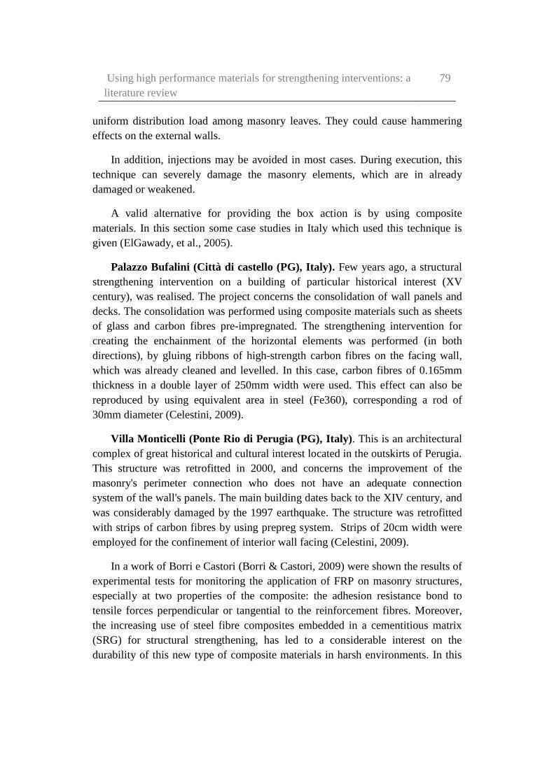
Using high performance materials for strengthening interventions: a
literature review
79
uniform distribution load among masonry leaves. They could cause hammering
effects on the external walls.
In addition, injections may be avoided in most cases. During execution, this
technique can severely damage the masonry elements, which are in already
damaged or weakened.
A valid alternative for providing the box action is by using composite
materials. In this section some case studies in Italy which used this technique is
given (ElGawady, et al., 2005).
Palazzo Bufalini (Città di castello (PG), Italy). Few years ago, a structural
strengthening intervention on a building of particular historical interest (XV
century), was realised. The project concerns the consolidation of wall panels and
decks. The consolidation was performed using composite materials such as sheets
of glass and carbon fibres pre-impregnated. The strengthening intervention for
creating the enchainment of the horizontal elements was performed (in both
directions), by gluing ribbons of high-strength carbon fibres on the facing wall,
which was already cleaned and levelled. In this case, carbon fibres of 0.165mm
thickness in a double layer of 250mm width were used. This effect can also be
reproduced by using equivalent area in steel (Fe360), corresponding a rod of
30mm diameter (Celestini, 2009).
Villa Monticelli (Ponte Rio di Perugia (PG), Italy). This is an architectural
complex of great historical and cultural interest located in the outskirts of Perugia.
This structure was retrofitted in 2000, and concerns the improvement of the
masonry's perimeter connection who does not have an adequate connection
system of the wall's panels. The main building dates back to the XIV century, and
was considerably damaged by the 1997 earthquake. The structure was retrofitted
with strips of carbon fibres by using prepreg system. Strips of 20cm width were
employed for the confinement of interior wall facing (Celestini, 2009).
In a work of Borri e Castori (Borri & Castori, 2009) were shown the results of
experimental tests for monitoring the application of FRP on masonry structures,
especially at two properties of the composite: the adhesion resistance bond to
tensile forces perpendicular or tangential to the reinforcement fibres. Moreover,
the increasing use of steel fibre composites embedded in a cementitious matrix
(SRG) for structural strengthening, has led to a considerable interest on the
durability of this new type of composite materials in harsh environments. In this
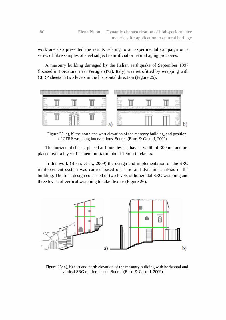
80 Elena Pinotti – Dynamic characterization of high-performance
materials for application to cultural heritage
work are also presented the results relating to an experimental campaign on a
series of fibre samples of steel subject to artificial or natural aging processes.
A masonry building damaged by the Italian earthquake of September 1997
(located in Forcatura, near Perugia (PG), Italy) was retrofitted by wrapping with
CFRP sheets in two levels in the horizontal direction (Figure 25).
Figure 25: a), b) the north and west elevation of the masonry building, and position
of CFRP wrapping interventions. Source (Borri & Castori, 2009).
The horizontal sheets, placed at floors levels, have a width of 300mm and are
placed over a layer of cement mortar of about 10mm thickness.
In this work (Borri, et al., 2009) the design and implementation of the SRG
reinforcement system was carried based on static and dynamic analysis of the
building. The final design consisted of two levels of horizontal SRG wrapping and
three levels of vertical wrapping to take flexure (Figure 26).
Figure 26: a), b) east and north elevation of the masonry building with horizontal and
vertical SRG reinforcement. Source (Borri & Castori, 2009).
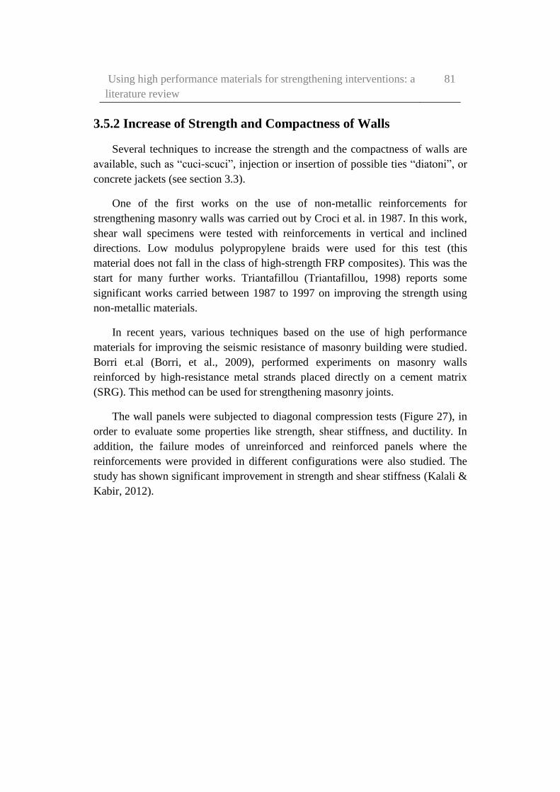
Using high performance materials for strengthening interventions: a
literature review
81
3.5.2 Increase of Strength and Compactness of Walls
Several techniques to increase the strength and the compactness of walls are
available, such as “cuci-scuci”, injection or insertion of possible ties “diatoni”, or
concrete jackets (see section 3.3).
One of the first works on the use of non-metallic reinforcements for
strengthening masonry walls was carried out by Croci et al. in 1987. In this work,
shear wall specimens were tested with reinforcements in vertical and inclined
directions. Low modulus polypropylene braids were used for this test (this
material does not fall in the class of high-strength FRP composites). This was the
start for many further works. Triantafillou (Triantafillou, 1998) reports some
significant works carried between 1987 to 1997 on improving the strength using
non-metallic materials.
In recent years, various techniques based on the use of high performance
materials for improving the seismic resistance of masonry building were studied.
Borri et.al (Borri, et al., 2009), performed experiments on masonry walls
reinforced by high-resistance metal strands placed directly on a cement matrix
(SRG). This method can be used for strengthening masonry joints.
The wall panels were subjected to diagonal compression tests (Figure 27), in
order to evaluate some properties like strength, shear stiffness, and ductility. In
addition, the failure modes of unreinforced and reinforced panels where the
reinforcements were provided in different configurations were also studied. The
study has shown significant improvement in strength and shear stiffness (Kalali &
Kabir, 2012).

82 Elena Pinotti – Dynamic characterization of high-performance
materials for application to cultural heritage
Figure 27: diagonal compression tests. Source (Borri, et al., 2009).
Among the different uses of CFRP materials, it is of considerable interest the
wrapping of wall panels subjected to compression load. Calderoni et al.
(Calderoni, et al., 2009) have conducted experiments on 21 pillars of tuff masonry
with pozzolanic mortar. This is the historical and contemporary masonry style in
Naples between the middle of the XV century and XX century. The influence of
radius of curvature of rounding of the edges, the type of fabric, and the number of
the reinforcing layers were studied (Aiello, et al., 2007). The aim of this kind of
works is to provide a further contribution to the experimental data currently
available, and investigate, in particular, the effectiveness of the reinforcement.
The experimental results show that the wrapping made with FRP significantly
changes the mechanical behaviour of the masonry, resulting in both an increase in
resistance and a change in the failure mechanism from brittle to ductile (an
extremely ductile behaviour). The change in resistance is highly dependent on the
extension of the wrapped section of the pillar. The effectiveness of the
reinforcement was smaller with increase in the cross sectional dimensions of the
structure. Furthermore, it was found that the increase in resistance is also strongly
influenced by the texture of the masonry. There is an increment of benefit when
the masonry is poor.
In the case of Chiesa di S. Maria, o Collegiata Pazzaglia (Montone (PG),
Italy), the aim of the intervention was to confine the apse and to contain the

Using high performance materials for strengthening interventions: a
literature review
83
pressures arising from the static situation. The structure was retrofitted by
applying a CFRP double wrap at two levels. It was applied on the outside of the
wall, along the whole perimeter of the apse. (Celestini, 2009).
Regarding the Ex convento SS. Trinità (Macchia dei Frati, Orvieto (TN),
Italy), the structural reinforcement intervention was applied for both the floors
and the dividing walls. The outside walls, with poor connection system, have been
joined solid by using a single layer of 30cm steel fibre strips (SRP). The
strengthening intervention was carried out below the roof level. (Celestini, 2009).
Corte Benedettina di Legnaro ((PD), Italy), is one of the first examples of
structural strengthening and restoration of historic buildings in Italy. The
strengthening system was realised by means of a kerb. This is a widespread
strengthening solution. The project involved the creation of two kerbs (made by
CFRP), placed on the roof. (Figure 28a). The kerbs were obtained laminating the
two side of the wall (internal and external facade), and connecting the two
reinforcement laminates, placed at ± 45 ° (Figure 28b) (Credali, 2009).
Figure 28: a) kerbs realised with carbon fibres placed up to the roof and the ceiling,
and b) horizontal and vertical kerbs placed on internal and external walls. Source
(Credali, 2009).
Another example of the application of FRP on masonry structure is on Villa
Bertani (Reggio Emilia (RE), Italy). The structure had suffered significant
damage from the earthquake in 1996. Internal and external CFRP curb (Figure
29), (placed on the floor of the roof level) have been replaced with concrete's curb
84 Elena Pinotti – Dynamic characterization of high-performance
materials for application to cultural heritage
in the frame of an earlier project. During the strengthening works, after the
installation of the first hoops, the building underwent a series of seismic shocks
caused by the earthquake in 2000. However, there was no further damage
reported despite the unhealthy condition of masonry at that time (Credali, 2009).
In the case of Grand Hotel di Alassio (Savona (SV), Italy), significant
retrofitting works were adopted. The masonry external façade showed significant.
In this case, hoops and bracing with carbon fibre strips were applied externally
and internally (Figure 30). The brick's drilling operation for the connectors
application was performed, in well-defined points, before the mortar injection. In
this way, a lattice structure on the two sides of the façade was obtained (Credali,
2009).
In Chiesa di S. Maria in Sovana (Sovana, Grosseto (GR), Italy), the
external hoops of the building (realised with tuff blocks) has forced the tuff
milling, for a thickness of about 10cm, in the areas in which the carbon
reinforcements had to be applied. The recovery of the part of the milled tuff has
been realised with elements of the same material, so that the reinforcement,
embedded in the wall, did not cause aesthetic problems (Credali, 2009).
Figure 29: horizontal and vertical CFRP kerbs on internal and external walls. Source
(Credali, 2009).

Using high performance materials for strengthening interventions: a
literature review
85
Figure 30: restoration intervention realised on the masonry external façade. Source
(Credali, 2009).
Another significant retrofitiing work was carried in a Library in the Basilica
of S. Antonio da Padova (Italy) (Figure 31). Here hybrid reinforced carbon-
aramid fibre systems were employed, because of better energy dissipation
capabilities. In addition, the reinforcing sheets were applied on both sides of the
masonry, and were connected by means of ARDFIX connectors, forming a
reticular structure (Credali, 2009).
Figure 31: strengthening intervention with hybrid reinforced carbon-aramid fibres
systems. Source (Credali, 2009).
In the past decade, there have been many studies involving the use of
advanced composite material for reinforcing masonry walls. Performance tests on
concrete masonry reinforced with a fiberglass/polyester-styrene composite and on
solid clay masonry reinforced with a fiberglass/epoxy material shown how these

86 Elena Pinotti – Dynamic characterization of high-performance
materials for application to cultural heritage
FRP systems may be effective in strengthening masonry walls both in case of in-
plane and in out-of-plane bending (Christensen, et al., 1996).
In another study (Papanicolaou, et al., 2011) , externally bonded grids were
used for increasing the load-carrying and deformation capability of unreinforced
masonry (URM) walls subjected to cyclic loads which induced in-plane flexure
combined with axial force, out-of-plane flexure, and in-plane shear with axial
force. The experimental study was performed on two groups of medium-scale,
single-wythe walls consisting of perforated fired clay bricks, or solid stone blocks.
The parameters considered were the number of reinforcement layers (one or two
layers, placed on internal/external sides), the type of mesh (open mesh structures
comprising carbon, glass or basalt fibres and polypropylene or polyester), the
matrix (mortars with different chemical compositions or epoxy resin) and, the
compressive stress applied to specimens subjected to in-plane loading. This study
have shown that the use of externally bonded grids is a promising alternative to
traditional techniques for upgrading existing masonry structures.
3.5.3 Strengthening of arches and vaults
Arches and vaults in historic buildings represent one of the most important
parts that are damaged during earthquakes. Strengthening methods can be applied
using the traditional techniques of tie-rods that compensate the thrust applied on
bearing walls. Adding buttresses or reinforced transverse vertical diaphragms are
also effective. Jacketing the extrados using concrete (with or without
reinforcement), must be avoided (Modena, et al., 2011).
Composite materials, such as FRP (Valluzzi, et al., 2001) or SRP/SRG, is
well suited for the recovery of structures. FRPs have high potential for such
specific applications, in comparison with heavier materials such as steel and
concrete, for the reinforcement of transverse diaphragms (Credali, 2009).
In bibliography experimental and numerical studies conducted on the
behaviour of vaults and arches strengthened at the extrados or intrados with FRP
strips or laminated, are available. Masonry vaults strengthened by different FRPs
(mainly glass or carbon) have been tested. All the results have shown
enhancement in strength and ductility of the strengthened vaults, the influence in
the ultimate strength of the width of the strips, and of the bond between the
laminate and the masonry (Valluzzi, et al., 2001).

Using high performance materials for strengthening interventions: a
literature review
87
Numerical investigations (FEM analysis) are also referred to the interfacial
behaviour of masonry-FRP (Briccoli Bati & Rovero, 2008) (Borri, et al., 2009)
(Basilio, et al., 2004), because the delamination is the reason of a brittle and
premature failure at the interface. The delamination can affect the effectiveness of
the strengthening strategies adopted. In order to properly consider the local
behaviour in the numerical modelling of the vaults, the bond performance analysis
has been also extended to curved substrate (Shrive, 2006) (Aiello & Conte, 2009)
(Aiello & Sciolti, 2009).
Some researches have conducted numerical investigations on semi-circular
vaults to study the influence of CFRP reinforcement to extrados (Aiello & Conte,
2009) (Borri, et al., 2009).
The results show that the effectiveness of FRP reinforcement increase in the
diameter of vault. The effectiveness was found seems to increase only when the
thickness is limited. This work highlights the worthlessness (for this point of
view) of the FRP reinforcement for vaults with an important thickness.
Basilio et al. (Basilio, et al., 2004) worked on semi-circular unstrengthen and
reinforced masonry arches. They were numerically modelled to evaluate the
effectiveness of different CFRP strengthening proposed. The results obtained in
the two cases (with or without reinforcement) are compared. At the end, the paper
presents results and conclusions regarding the optimal strengthening of masonry
arches.
Mahini et al. performed nonlinear finite element analysis on a historical
building located in Yazd, Iran to study its response and failure mechanisms when
subjected to lateral loads. The influence of CFRP sheets on the seismic
performance of vault was also investigated (also include the results from the
analysis) (Mahini, et al., 2007).
Briccoli et al. (Briccoli Bati & Rovero, 2009), conducted experiments on
models of masonry arches reinforced by CFRP strips. Here, CFRP strips of
different width was bonded to the intrados. The aim of the study was to evaluate
the impact of different reinforcement configurations on the strength of masonry
arches. It was found that the kinematic ductility decreases with increase in the
width of strip in the strip width, highlighting the stiffening action produced by
increasing of the reinforcement (Caratelli, et al., 2009) (Briccoli Bati & Rovero,
2008) (Foraboschi, 2004).
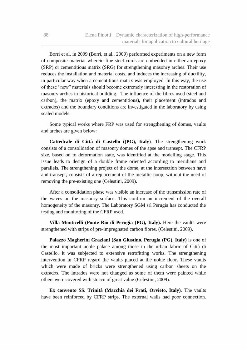
88 Elena Pinotti – Dynamic characterization of high-performance
materials for application to cultural heritage
Borri et al. in 2009 (Borri, et al., 2009) performed experiments on a new form
of composite material wherein fine steel cords are embedded in either an epoxy
(SRP) or cementitious matrix (SRG) for strengthening masonry arches. Their use
reduces the installation and material costs, and induces the increasing of ductility,
in particular way when a cementitious matrix was employed. In this way, the use
of these “new” materials should become extremely interesting in the restoration of
masonry arches in historical building. The influence of the fibres used (steel and
carbon), the matrix (epoxy and cementitious), their placement (intrados and
extrados) and the boundary conditions are investigated in the laboratory by using
scaled models.
Some typical works where FRP was used for strengthening of domes, vaults
and arches are given below:
Cattedrale di Città di Castello ((PG), Italy). The strengthening work
consists of a consolidation of masonry domes of the apse and transept. The CFRP
size, based on to deformation state, was identified at the modelling stage. This
issue leads to design of a double frame oriented according to meridians and
parallels. The strengthening project of the dome, at the intersection between nave
and transept, consists of a replacement of the metallic hoop, without the need of
removing the pre-existing one (Celestini, 2009).
After a consolidation phase was visible an increase of the transmission rate of
the waves on the masonry surface. This confirm an increment of the overall
homogeneity of the masonry. The Laboratory SGM srl Perugia has conducted the
testing and monitoring of the CFRP used.
Villa Monticelli (Ponte Rio di Perugia (PG), Italy). Here the vaults were
strengthened with strips of pre-impregnated carbon fibres. (Celestini, 2009).
Palazzo Magherini Graziani (San Giustino, Perugia (PG), Italy) is one of
the most important noble palace among those in the urban fabric of Città di
Castello. It was subjected to extensive retrofitting works. The strengthening
intervention in CFRP regard the vaults placed at the noble floor. These vaults
which were made of bricks were strengthened using carbon sheets on the
extrados. The intrados were not changed as some of them were painted while
others were covered with stucco of great value (Celestini, 2009).
Ex convento SS. Trinità (Macchia dei Frati, Orvieto, Italy). The vaults
have been reinforced by CFRP strips. The external walls had poor connection.

Using high performance materials for strengthening interventions: a
literature review
89
The improvement of monolithic behaviour has been made using steel fibre strips
(SRP) (Celestini, 2009).
Palazzo Reale (Milano, Italy). The masonry vaults of this structure was
strengthened using GFRP sheets on the extrados and by placing aramid bars on
the lateral masonry walls for anchoring the extremities of the GFRP sheets
(Celestini, 2009).
Basilica di S. Francesco (Assisi, Italy). The Italian earthquake of 1997 called
for an urgent strengthening of the tympanum and of the vaults to prevent their
collapse, for preventing the global collapse (Figure 32). The inner surface of the
vaults were covered with frescoes, thus making any strengthening method on this
surface impossible. Consequently, it was impossible to recover the deformations
and to re-establish an adequate curvature and autonomous bearing capacity. Many
studies, researches and mathematical models were performed to choose an
efficient solution. Finally, it was decided to provide small ribs on the extrados.
Figure 33 shows the strengthened structure (Croci, 2000).
Figure 32: cracks and deformation in the vaults with relative displacement till 30cm.
Source (Croci, 2000).
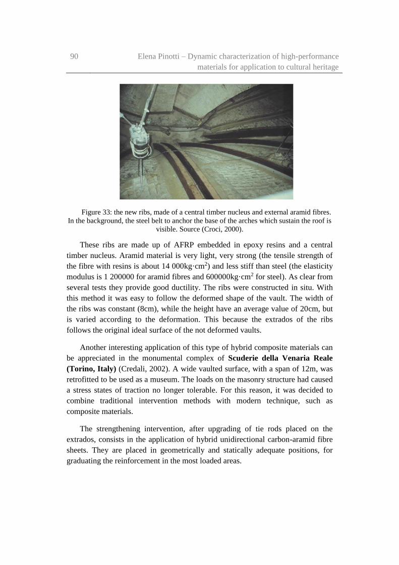
90 Elena Pinotti – Dynamic characterization of high-performance
materials for application to cultural heritage
Figure 33: the new ribs, made of a central timber nucleus and external aramid fibres.
In the background, the steel belt to anchor the base of the arches which sustain the roof is
visible. Source (Croci, 2000).
These ribs are made up of AFRP embedded in epoxy resins and a central
timber nucleus. Aramid material is very light, very strong (the tensile strength of
the fibre with resins is about 14 000kg·cm2) and less stiff than steel (the elasticity
modulus is 1 200000 for aramid fibres and 600000kg·cm2 for steel). As clear from
several tests they provide good ductility. The ribs were constructed in situ. With
this method it was easy to follow the deformed shape of the vault. The width of
the ribs was constant (8cm), while the height have an average value of 20cm, but
is varied according to the deformation. This because the extrados of the ribs
follows the original ideal surface of the not deformed vaults.
Another interesting application of this type of hybrid composite materials can
be appreciated in the monumental complex of Scuderie della Venaria Reale
(Torino, Italy) (Credali, 2002). A wide vaulted surface, with a span of 12m, was
retrofitted to be used as a museum. The loads on the masonry structure had caused
a stress states of traction no longer tolerable. For this reason, it was decided to
combine traditional intervention methods with modern technique, such as
composite materials.
The strengthening intervention, after upgrading of tie rods placed on the
extrados, consists in the application of hybrid unidirectional carbon-aramid fibre
sheets. They are placed in geometrically and statically adequate positions, for
graduating the reinforcement in the most loaded areas.
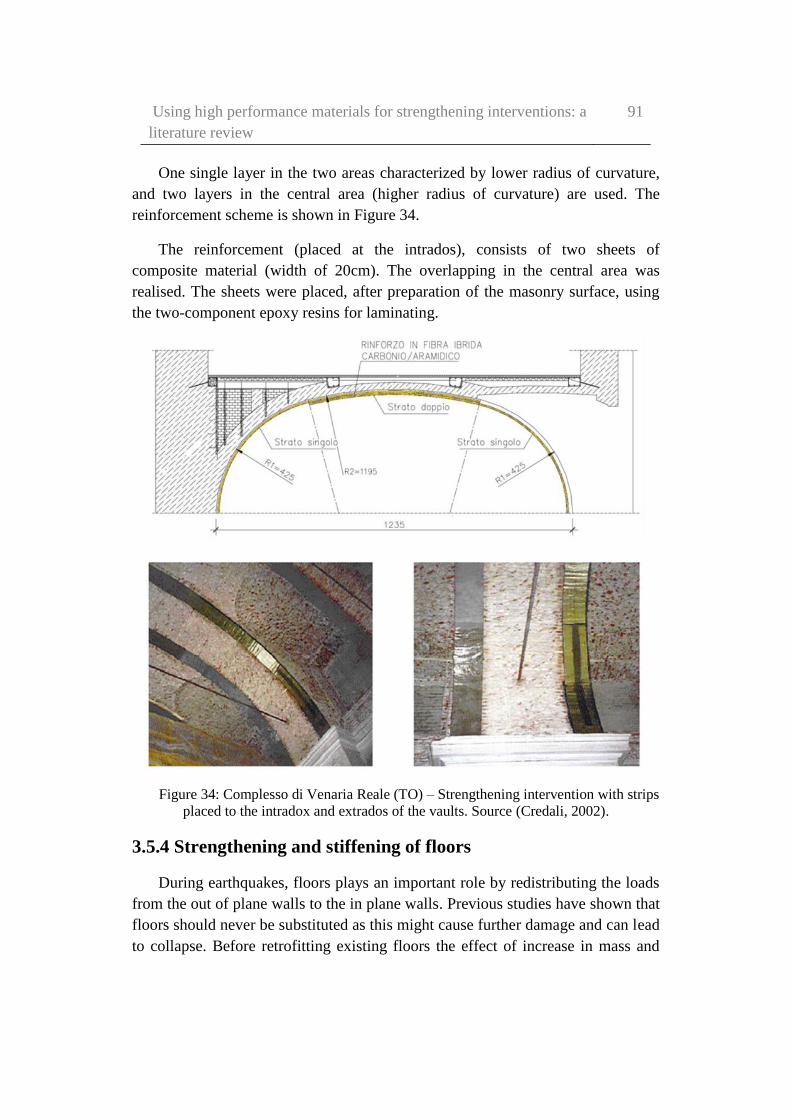
Using high performance materials for strengthening interventions: a
literature review
91
One single layer in the two areas characterized by lower radius of curvature,
and two layers in the central area (higher radius of curvature) are used. The
reinforcement scheme is shown in Figure 34.
The reinforcement (placed at the intrados), consists of two sheets of
composite material (width of 20cm). The overlapping in the central area was
realised. The sheets were placed, after preparation of the masonry surface, using
the two-component epoxy resins for laminating.
Figure 34: Complesso di Venaria Reale (TO) – Strengthening intervention with strips
placed to the intradox and extrados of the vaults. Source (Credali, 2002).
3.5.4 Strengthening and stiffening of floors
During earthquakes, floors plays an important role by redistributing the loads
from the out of plane walls to the in plane walls. Previous studies have shown that
floors should never be substituted as this might cause further damage and can lead
to collapse. Before retrofitting existing floors the effect of increase in mass and

92 Elena Pinotti – Dynamic characterization of high-performance
materials for application to cultural heritage
stiffness due to the strengthening strategies should be studied. Also, connections
between floors and the surrounding walls have to be ensured for redistribution of
loads (Parisi & Piazza, 2002) (Modena, et al., 2011).
A simple way to strengthen old wooden floors is by adding another layer of
wooden planks. But, this method will not help in redistributing the lateral loads.
Double planking is another popular method wherein planks are arranged in
orthogonal or at an angle and is connected using tongue and groove joints or using
nails or screws.
Metallic belts, FRP strips and metallic tie beam bracing can also be used to
stiffen the floor and the wall-floor connection (Corradi, et al., 2006). FRP strips
can be arranged in a crossed pattern underneath the wooden floors. A layer of
reinforced concrete can also be used, but must be studied carefully as this
procedure causes an increase in dead load.
3.5.5 Confinement of masonry columns
Wrapping the columns by FRP sheets or laminates is one of the modern
technique for strengthening columns. They were introduced in the last decade as
an effective alternative for wood and steel ties (Corradi, et al., 2007) (Sivaraja, et
al., 2013).
Since ancient times, different kind of methods were used to reinforce
compressed elements (Alecci, et al., 2009). Different materials were used for this.
Traditionally, masonry columns were confined by using reinforced concrete (or
steel) jacketing (D’Ambra, et al., 2009), or iron bands are used, still hot or with
special devices for example, for producing a self-stress state into the compressed
elements. These system were effective in preventing the brittle failure due to
compressive loads, seismic forces and creep effects. These materials were then
replaced by FRP.
There are many benefits of using FRP to confine concrete or masonry
elements. Using FRP will not result in an increase in the area of the members thus
maintaing the functionality of the structure. FRP is also light, so it does not add
any extra dead load. FRP can also be applied very easily thus saving significant
time. Numerous researches were performed on this topic for studying the benefits
of FRP interventions on both in plane and out-of-plane behaviour of masonry
walls (ElGawady, et al., 2005) (Marcari, et al., 2007).

Using high performance materials for strengthening interventions: a
literature review
93
In both Villa Reale in Monza (Milano, Italy) (ResinProget, 2012) and Real
Albergo dei Poveri a Napoli (Italy) (Olympus, 2016) masonry walls were
confined (Figure 35). In the first case columns were strengthened with structural
plaster and a series of hoops of aramid fabric. While in the second case, aramid
fabric was applied by using connectors to improve the confinement efficiency.
Figure 35: strengthening intervention with AFRP in Villa Reale in Monza (sx), and
Real Albergo dei Poveri a Napoli (dx). Source (Olympus, 2016) and (ResinProget, 2012).
A review of state of the art literatures shows that only few studies were
carried regarding the application of FRP to increase the axial strength and
deformation capacity of masonry columns (D’Ambra, et al., 2009) (Aiello, et al.,
2007) (Corradi, et al., 2007). These studies have shown that as the traditional
methods add a significant amount of dead load to the structure which lead to an
increase in earthquake loads, they are not suitable for seismic strengthening. The
increase in dead load can also result in an unsafe foundation and consequently
lead to strengthening foundations also.
As FRP has poor resistance to cutting, FRP confinemet in colums with sharp
corners (polygonal sections) have shown premature breakage of fibres (Borri &
Corradi, 2009). However, this problem can be solved by using curved steel
sections at these edges. Another viable alternative is to use new material such as
SRG (Steel Reinforced grouts) and SRP (Steel Reinforced Polymers). It was also
found that using cement mortars to connect metal fabric to masonry colums
resulted in some issues related to the flexural stiffness of metallic fibres which
does not allow (for columns with reduced cross-sections) to mobilise the tensile
strength of metal fibres when the columns are compressed.
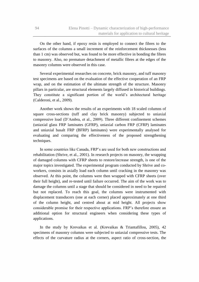
94 Elena Pinotti – Dynamic characterization of high-performance
materials for application to cultural heritage
On the other hand, if epoxy resin is employed to connect the fibres to the
surfaces of the columns a small increment of the reinforcement thicknesses (less
than 1 cm) was observed but, was found to be more effective in bonding the fibres
to masonry. Also, no premature detachment of metallic fibres at the edges of the
masonry columns were observed in this case.
Several experimental researches on concrete, brick masonry, and tuff masonry
test specimens are based on the evaluation of the effective cooperation of an FRP
wrap, and on the estimation of the ultimate strength of the structure. Masonry
pillars in particular, are structural elements largely diffused in historical buildings.
They constitute a significant portion of the world’s architectural heritage
(Calderoni, et al., 2009).
Another work shows the results of an experiments with 18 scaled columns of
square cross-sections (tuff and clay brick masonry) subjected to uniaxial
compressive load (D’Ambra, et al., 2009). Three different confinement schemes
(uniaxial glass FRP laminates (GFRP), uniaxial carbon FRP (CFRP) laminates
and uniaxial basalt FRP (BFRP) laminates) were experimentally analysed for
evaluating and comparing the effectiveness of the proposed strengthening
techniques.
In some countries like Canada, FRP’s are used for both new constructions and
rehabilitation (Shrive, et al., 2001). In research projects on masonry, the wrapping
of damaged columns with CFRP sheets to restore/increase strength, is one of the
major topics investigated. The experimental program conducted by Shrive and co-
workers, consists in axially load each column until cracking in the masonry was
observed. At this point, the columns were then wrapped with CFRP sheets (over
their full height), and re-tested until failure occurred. The aim of the work was to
damage the columns until a stage that should be considered in need to be repaired
but not replaced. To reach this goal, the columns were instrumented with
displacement transducers (one at each corner) placed approximately at one third
of the column height, and centred about at mid height. All projects show
considerable promise for their respective applications. FRP’s therefore ensure an
additional option for structural engineers when considering these types of
applications.
In the study by Krevaikas et al. (Krevaikas & Triantafillou, 2005), 42
specimens of masonry columns were subjected to uniaxial compressive tests. The
effects of the curvature radius at the corners, aspect ratio of cross-section, the
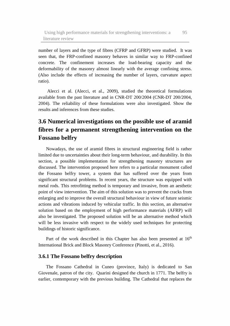
Using high performance materials for strengthening interventions: a
literature review
95
number of layers and the type of fibres (CFRP and GFRP) were studied. It was
seen that, the FRP-confined masonry behaves in similar way to FRP-confined
concrete. The confinement increases the load-bearing capacity and the
deformability of the masonry almost linearly with the average confining stress.
(Also include the effects of increasing the number of layers, curvature aspect
ratio).
Alecci et al. (Alecci, et al., 2009), studied the theoretical formulations
available from the past literature and in CNR-DT 200/2004 (CNR-DT 200/2004,
2004). The reliability of these formulations were also investigated. Show the
results and inferences from these studies.
3.6 Numerical investigations on the possible use of aramid
fibres for a permanent strengthening intervention on the
Fossano belfry
Nowadays, the use of aramid fibres in structural engineering field is rather
limited due to uncertainties about their long-term behaviour, and durability. In this
section, a possible implementation for strengthening masonry structures are
discussed. The intervention proposed here refers to a particular monument called
the Fossano belfry tower, a system that has suffered over the years from
significant structural problems. In recent years, the structure was equipped with
metal rods. This retrofitting method is temporary and invasive, from an aesthetic
point of view intervention. The aim of this solution was to prevent the cracks from
enlarging and to improve the overall structural behaviour in view of future seismic
actions and vibrations induced by vehicular traffic. In this section, an alternative
solution based on the employment of high performance materials (AFRP) will
also be investigated. The proposed solution will be an alternative method which
will be less invasive with respect to the widely used techniques for protecting
buildings of historic significance.
Part of the work described in this Chapter has also been presented at 16th
International Brick and Block Masonry Conference (Pinotti, et al., 2016).
3.6.1 The Fossano belfry description
The Fossano Cathedral in Cuneo (province, Italy) is dedicated to San
Giovenale, patron of the city. Quarini designed the church in 1771. The belfry is
earlier, contemporary with the previous building. The Cathedral that replaces the
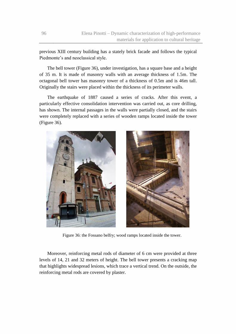
96 Elena Pinotti – Dynamic characterization of high-performance
materials for application to cultural heritage
previous XIII century building has a stately brick facade and follows the typical
Piedmonte’s and neoclassical style.
The bell tower (Figure 36), under investigation, has a square base and a height
of 35 m. It is made of masonry walls with an average thickness of 1.5m. The
octagonal bell tower has masonry tower of a thickness of 0.5m and is 46m tall.
Originally the stairs were placed within the thickness of its perimeter walls.
The earthquake of 1887 caused a series of cracks. After this event, a
particularly effective consolidation intervention was carried out, as core drilling,
has shown. The internal passages in the walls were partially closed, and the stairs
were completely replaced with a series of wooden ramps located inside the tower
(Figure 36).
Figure 36: the Fossano belfry; wood ramps located inside the tower.
Moreover, reinforcing metal rods of diameter of 6 cm were provided at three
levels of 14, 21 and 32 meters of height. The bell tower presents a cracking map
that highlights widespread lesions, which trace a vertical trend. On the outside, the
reinforcing metal rods are covered by plaster.

Using high performance materials for strengthening interventions: a
literature review
97
From a preliminary surface inspection, the masonry walls of the belfry seems
to be in a good condition. But, the core drillings have shown a non-homogenous
masonry, located within the outer layers of the perimeter walls.
After the experimental campaign, the results confirmed serious concerns
about the stability of the monument. The last safety operation works were
performed subsequent to further opening of vertical cracks which were visible
inside the monument in 2012. The retrofitting operation included steel tie-rods
placed both inside and outside the bell tower in eleven levels from the ground.
(Figure 37). Moreover, a vertical steel structure was also added, which puts in
tension the internal cerclage by means of diagonal elements.
Figure 37: the belfry of the Fossano Cathedral with the strengthening intervention.
A complete and detailed survey to estimate the cracks carried out in recent
years, together with core drilling, and a structural identification of the structures
was performed. This allowed for calibrating a FE model.
3.6.2 Finite Element (FE) model calibration
A FE model of the bell tower was created using the material properties
collected from experimental tests, in addition to the original documentation
(Figure 38). The belfry was the subject of previous studies (Ceravolo, et al.,
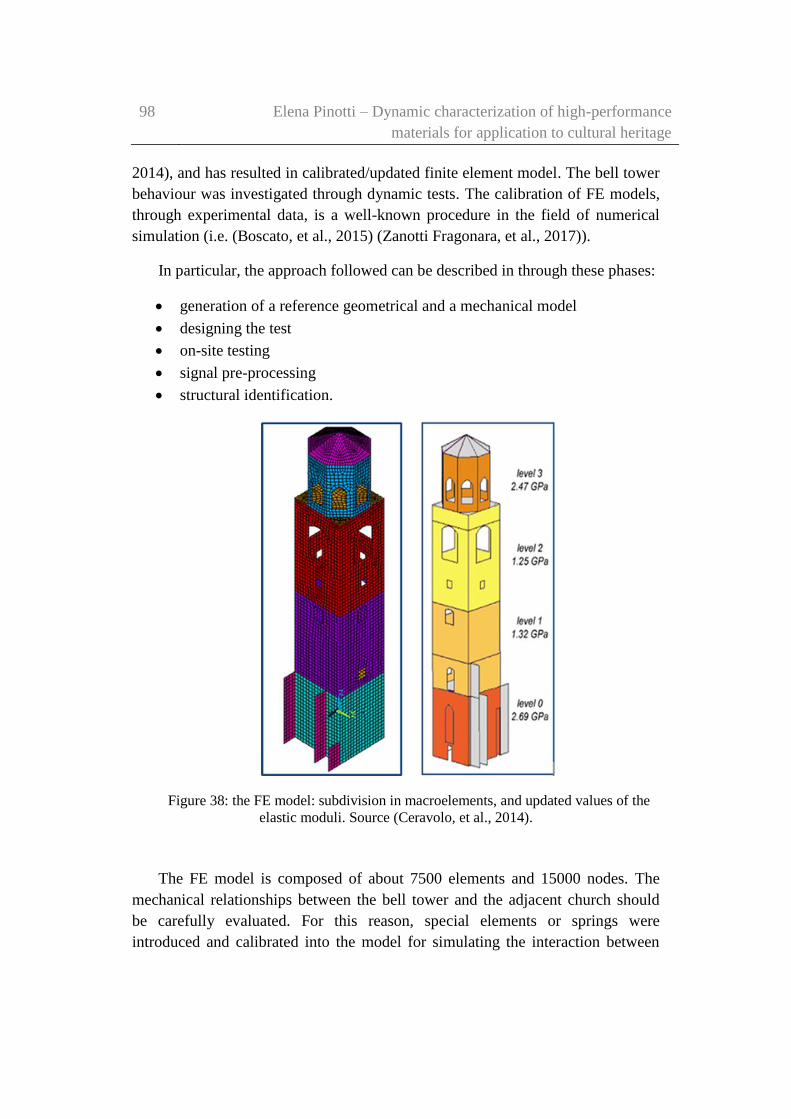
98 Elena Pinotti – Dynamic characterization of high-performance
materials for application to cultural heritage
2014), and has resulted in calibrated/updated finite element model. The bell tower
behaviour was investigated through dynamic tests. The calibration of FE models,
through experimental data, is a well-known procedure in the field of numerical
simulation (i.e. (Boscato, et al., 2015) (Zanotti Fragonara, et al., 2017)).
In particular, the approach followed can be described in through these phases:
generation of a reference geometrical and a mechanical model
designing the test
on-site testing
signal pre-processing
structural identification.
Figure 38: the FE model: subdivision in macroelements, and updated values of the
elastic moduli. Source (Ceravolo, et al., 2014).
The FE model is composed of about 7500 elements and 15000 nodes. The
mechanical relationships between the bell tower and the adjacent church should
be carefully evaluated. For this reason, special elements or springs were
introduced and calibrated into the model for simulating the interaction between
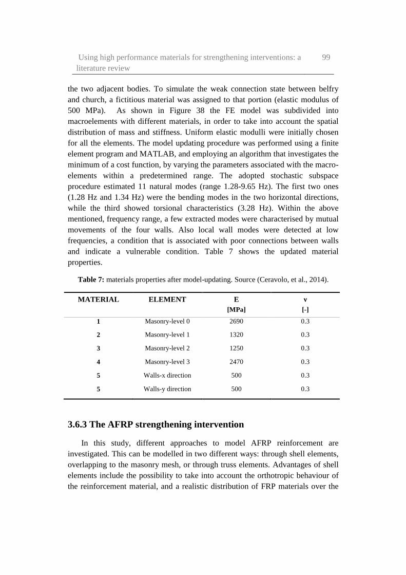
Using high performance materials for strengthening interventions: a
literature review
99
the two adjacent bodies. To simulate the weak connection state between belfry
and church, a fictitious material was assigned to that portion (elastic modulus of
500 MPa). As shown in Figure 38 the FE model was subdivided into
macroelements with different materials, in order to take into account the spatial
distribution of mass and stiffness. Uniform elastic modulli were initially chosen
for all the elements. The model updating procedure was performed using a finite
element program and MATLAB, and employing an algorithm that investigates the
minimum of a cost function, by varying the parameters associated with the macro-
elements within a predetermined range. The adopted stochastic subspace
procedure estimated 11 natural modes (range 1.28-9.65 Hz). The first two ones
(1.28 Hz and 1.34 Hz) were the bending modes in the two horizontal directions,
while the third showed torsional characteristics (3.28 Hz). Within the above
mentioned, frequency range, a few extracted modes were characterised by mutual
movements of the four walls. Also local wall modes were detected at low
frequencies, a condition that is associated with poor connections between walls
and indicate a vulnerable condition. Table 7 shows the updated material
properties.
Table 7: materials properties after model-updating. Source (Ceravolo, et al., 2014).
MATERIAL ELEMENT E ν
[MPa] [-]
1 Masonry-level 0 2690 0.3
2 Masonry-level 1 1320 0.3
3 Masonry-level 2 1250 0.3
4 Masonry-level 3 2470 0.3
5 Walls-x direction 500 0.3
5 Walls-y direction 500 0.3
3.6.3 The AFRP strengthening intervention
In this study, different approaches to model AFRP reinforcement are
investigated. This can be modelled in two different ways: through shell elements,
overlapping to the masonry mesh, or through truss elements. Advantages of shell
elements include the possibility to take into account the orthotropic behaviour of
the reinforcement material, and a realistic distribution of FRP materials over the
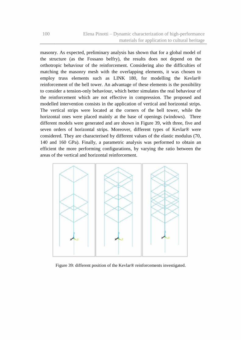
100 Elena Pinotti – Dynamic characterization of high-performance
materials for application to cultural heritage
masonry. As expected, preliminary analysis has shown that for a global model of
the structure (as the Fossano belfry), the results does not depend on the
orthotropic behaviour of the reinforcement. Considering also the difficulties of
matching the masonry mesh with the overlapping elements, it was chosen to
employ truss elements such as LINK 180, for modelling the Kevlar®
reinforcement of the bell tower. An advantage of these elements is the possibility
to consider a tension-only behaviour, which better simulates the real behaviour of
the reinforcement which are not effective in compression. The proposed and
modelled intervention consists in the application of vertical and horizontal strips.
The vertical strips were located at the corners of the bell tower, while the
horizontal ones were placed mainly at the base of openings (windows). Three
different models were generated and are shown in Figure 39, with three, five and
seven orders of horizontal strips. Moreover, different types of Kevlar® were
considered. They are characterised by different values of the elastic modulus (70,
140 and 160 GPa). Finally, a parametric analysis was performed to obtain an
efficient the more performing configurations, by varying the ratio between the
areas of the vertical and horizontal reinforcement.
Figure 39: different position of the Kevlar® reinforcements investigated.

Using high performance materials for strengthening interventions: a
literature review
101
3.6.4 Analysis and results
Pushover analyses were carried out in both the horizontal directions by
varying the following parameters of the reinforcement:
elastic modulus
number and arrangement of the fabrics
size.
For modelling masonry an orthotropic material was adopted, together with a
maximum stress failure criterion. It is characterised by different values of strength
in tension, compression and shear. In addition, a brittle behaviour in tension was
simulated, considering higher values of the stiffness reduction factor. Instead, a
linear elastic behaviour was assumed for the reinforcement material with tension-
only capability (no stiffness in compression) for the truss elements. The pushover
curves of the reinforced structure with AFRP (elastic modulus of 70 GPa) are
shown in Figure 40.
Figure 40: pushover curves, in x direction (Kevlar® 29 with E = 70GPa).
The results compare three different positions of the reinforcement strips, with
the belfry in its original condition (without reinforcement). Figure 41 shows the
results with AFRP reinforcement having an elastic modulus of 160GPa.

102 Elena Pinotti – Dynamic characterization of high-performance
materials for application to cultural heritage
An increase in ductility is attained for all reinforcement types and
configurations investigated. The ultimate displacement of the original structure
(without reinforcement) was about 12 cm while in case of reinforced bell tower it
was 20 to 30 cm (an increment of about 70 to 150%).
Figure 41: pushover curves, in x direction (Kevlar® 49 with E = 160 GPa).
The best performance in terms of ultimate displacement is obtained for the
model with reinforcement arranged in seven layers with the stiffest AFRP.
Interesting improvements in terms of strength are not observed, because the
ultimate horizontal force was more or less same for the unreinforced belfry and
for the different configurations of reinforcement. In these analyses, the same area
was provided for both horizontal and vertical reinforcement stripes.
Another parametric study was performed by varying the ratio between the
areas of the vertical and horizontal reinforcement. Figures 43-44 shows the results
for maximum displacement with the ratio between the areas of the strips. Three
different values for the vertical and horizontal reinforcement, (considering the
same ratio between the two), were also analysed and the results are shown.
Generally, a good performance in terms of ultimate displacement was
obtained for similar values of the area of vertical and horizontal reinforcement
strips. It corresponds to a ratio of 0.8÷1.2. The maximum values for the ultimate
displacements are obtained with horizontal and vertical reinforcement of 1000
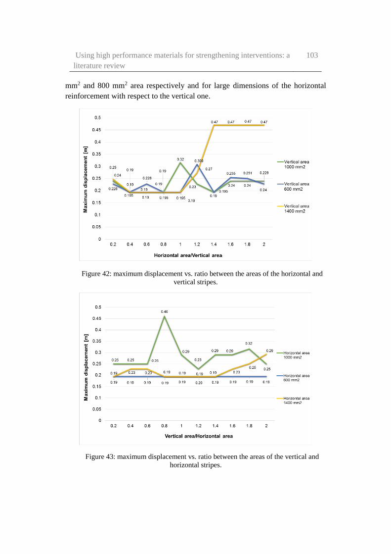
Using high performance materials for strengthening interventions: a
literature review
103
mm2 and 800 mm2 area respectively and for large dimensions of the horizontal
reinforcement with respect to the vertical one.
Figure 42: maximum displacement vs. ratio between the areas of the horizontal and
vertical stripes.
Figure 43: maximum displacement vs. ratio between the areas of the vertical and
horizontal stripes.
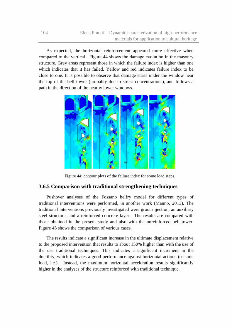
104 Elena Pinotti – Dynamic characterization of high-performance
materials for application to cultural heritage
As expected, the horizontal reinforcement appeared more effective when
compared to the vertical. Figure 44 shows the damage evolution in the masonry
structure. Grey areas represent those in which the failure index is higher than one
which indicates that it has failed. Yellow and red indicates failure index to be
close to one. It is possible to observe that damage starts under the window near
the top of the bell tower (probably due to stress concentrations), and follows a
path in the direction of the nearby lower windows.
Figure 44: contour plots of the failure index for some load steps.
3.6.5 Comparison with traditional strengthening techniques
Pushover analyses of the Fossano belfry model for different types of
traditional interventions were performed, in another work (Manno, 2013). The
traditional interventions previously investigated were grout injection, an auxiliary
steel structure, and a reinforced concrete layer. The results are compared with
those obtained in the present study and also with the unreinforced bell tower.
Figure 45 shows the comparison of various cases.
The results indicate a significant increase in the ultimate displacement relative
to the proposed intervention that results to about 150% higher than with the use of
the use traditional techniques. This indicates a significant increment in the
ductility, which indicates a good performance against horizontal actions (seismic
load, i.e.). Instead, the maximum horizontal acceleration results significantly
higher in the analyses of the structure reinforced with traditional technique.

Using high performance materials for strengthening interventions: a
literature review
105
Figure 45: pushover curves relative to the unreinforced structure, the proposed
intervention and the adoption of traditional techniques.

106 Elena Pinotti – Dynamic characterization of high-performance
materials for application to cultural heritage
Chapter 4
A prototype-testing machine for
the dynamic characterization of
high performance materials
FRPs are commonly used for structural repair and strengthening interventions,
and exhibit high potential for applications to existing buildings, including heritage
constructions. For years, uncertainties connected with the long-term behaviour
and durability of FRPs materials have often made the designers reluctant to use
them in structural engineering applications.
In this Chapter, an innovative and alternative method for measuring the
damping, and the nonlinear behaviour of high-strength fibre materials is
described. In particular, Kevlar® 29 (para aramid), silicon carbide (SiC) and
carbon fibres were tested. The method used is based on resonant response
characterization of a spring-mass system excited by a sine-wave forcing term. It is
applied as a vertical force to the suspended mass. The damping is obtained from
the measured resonance quality factor Q, and the non-linearity index is obtained
through the evaluation of the “backbone curve”. To evaluate low damping values,
special attention has been taken for ensure that the energy dispersions are much
smaller with comparison to the energy dispersions due to the material damping of
the tested sample.

A prototype-testing machine for the dynamic characterization of
high performance materials
107
The non-linearity index is obtained from the resonance profile variations as a
function of the forcing term amplitude. This index could be used for damage
detection, or Structural Health Monitoring applications.
Part of the work described in this Chapter has also been published in
Experimental Mechanics (Ceravolo, et al., 2017).
4.1 Introduction
High performance fibre materials have recently received growing attention
because they are versatile materials, and can be used in different ways and for
different applications (see previous chapters). More applications regard force
transmission (e.g. fibres in composites materials), signal transmission (El Abdi, et
al., 2008), and protection and coating (e.g. textile tissue), and much more. In any
cases, fibres are always subject during use to deformation and vibrations. This
occurs both if they are embedded in a matrix or not. Therefore, is very important
to study the dynamic behaviour of the fibres with particular attention to their
damping characteristics. They influence the dynamic response, and consequently
their efficiency (Nciri, et al., 2017) (Pambaguian & Mervel, 1996) (Grouvea, et
al., 2008).
The research field of high-strength low damping fibres is of the utter interest
for structural engineering, with high potential for significant advancements in the
some specific areas, including the seismic protection and monitoring of cultural
heritage. Structural engineers are typically interested to obtaining information
about the mechanical damping in high-strength fibres in order to evaluate some
features such as:
energy absorption capability
clarify the effects of weaving on their behaviour
to evaluate the use non-destructive tests for evaluating their
characteristics (including the damping and the non-linear behaviour),
also for damage assessment purposes.
In this work, the tests were conducted by using a multifilament tow of parallel
fibres. Several techniques for testing the damping behaviour of composite
materials are described in earlier studies, and can be found after investigation of
the available literature (Ochola, et al., 2004). Instead, research on free-standing
fibres are less common. For this reason, is not easy to find data in the open
108 Elena Pinotti – Dynamic characterization of high-performance
materials for application to cultural heritage
literature on dynamic characteristics of free-standing fibres. These data, could be
very useful for the evaluation of the ageing, damage, or also for the dynamic
behaviour of composite materials. It is frequent that standard equipment used for
the evaluation of the mechanical and dynamical properties are unsuitable for the
investigation of thin fibres and yarns.
A universal testing machine for an accurate dynamic characterization of thin
fibres (with diameter in the order of 10 µm) and/or a small yarn does not exist
(Więcek, 2014). Different is in for composite materials (Botelho, et al., 2006)
(Cerny, et al., 2000) (El-Mahdy & Gadelrab, 2000) (Nagasankar, et al., 2014)
(Berthelot & Sefrani, 2004). The main difficulties are related to the sample’
geometry constrains, with particular attention to its handling and clamping. This
research work suggests a possible approach to the problem.
Experimental methods currently used, and potentially applicable for the
evaluation of the dynamic moduli and damping of composite materials, include:
the free vibration technique (impulse technique),
the rotating-beam deflection,
the forced vibration response,
the resonance technique,
the continuous wave or pulse propagation technique (Botelho, et al.,
2006), (Wei & Kukureka, 2000) (Černý, et al., 2000).
A popular and simple test is the impulse technique. It can be used to
measuring natural frequencies and loss factors, for example (Nagasankar, et al.,
2014). The input is provided through an instrumented impact hammer, and the
response is usually captured by an accelerometer or visualised by means of a
high-speed camera (Valtorta, et al., 2005) (Rice, et al., 2014), and read by means
of an acquisition card (Berthelot & Sefrani, 2004). Different authors such as
Suarez et al. (Suarez, et al., 1984), Suarez and Gibson (Suarez & Gibson, 1984)
and Crane and Gillespie (Crane & Gillespie, 1991) propose as first the impulse
technique for the characterisation of composites materials, but these studies have
not been subsequently applied to fibres. The requirement of high sensitivity of the
vibration amplitude sensor is a great obstacle that arises due to geometrical
reasons towards the application of the impulse technique to high stiffness fibres.
In another work, Di Carlo and Williams (Di Carlo & Williams, 1980) tested the
damping properties of boron and SiC fibres with a free-decay technique. They
employed a capacitive sensor in which the fibre was part of the capacitor. Despite
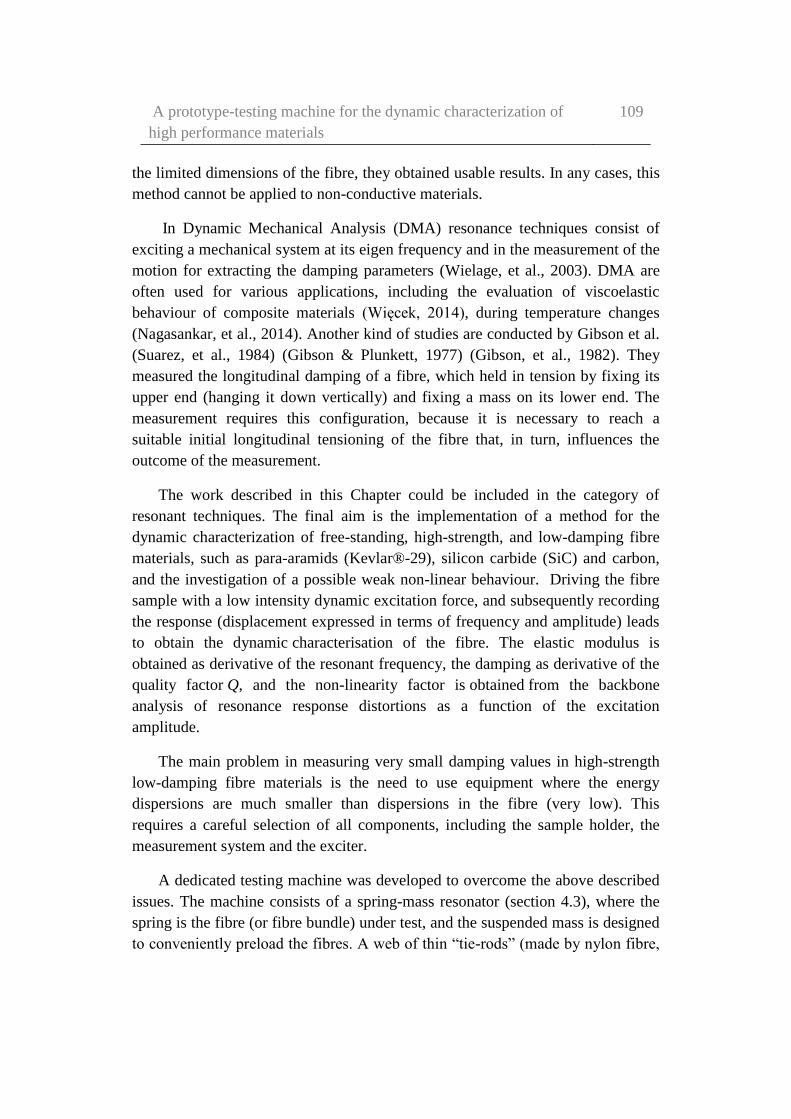
A prototype-testing machine for the dynamic characterization of
high performance materials
109
the limited dimensions of the fibre, they obtained usable results. In any cases, this
method cannot be applied to non-conductive materials.
In Dynamic Mechanical Analysis (DMA) resonance techniques consist of
exciting a mechanical system at its eigen frequency and in the measurement of the
motion for extracting the damping parameters (Wielage, et al., 2003). DMA are
often used for various applications, including the evaluation of viscoelastic
behaviour of composite materials (Więcek, 2014), during temperature changes
(Nagasankar, et al., 2014). Another kind of studies are conducted by Gibson et al.
(Suarez, et al., 1984) (Gibson & Plunkett, 1977) (Gibson, et al., 1982). They
measured the longitudinal damping of a fibre, which held in tension by fixing its
upper end (hanging it down vertically) and fixing a mass on its lower end. The
measurement requires this configuration, because it is necessary to reach a
suitable initial longitudinal tensioning of the fibre that, in turn, influences the
outcome of the measurement.
The work described in this Chapter could be included in the category of
resonant techniques. The final aim is the implementation of a method for the
dynamic characterization of free-standing, high-strength, and low-damping fibre
materials, such as para-aramids (Kevlar®-29), silicon carbide (SiC) and carbon,
and the investigation of a possible weak non-linear behaviour. Driving the fibre
sample with a low intensity dynamic excitation force, and subsequently recording
the response (displacement expressed in terms of frequency and amplitude) leads
to obtain the dynamic characterisation of the fibre. The elastic modulus is
obtained as derivative of the resonant frequency, the damping as derivative of the
quality factor Q, and the non-linearity factor is obtained from the backbone
analysis of resonance response distortions as a function of the excitation
amplitude.
The main problem in measuring very small damping values in high-strength
low-damping fibre materials is the need to use equipment where the energy
dispersions are much smaller than dispersions in the fibre (very low). This
requires a careful selection of all components, including the sample holder, the
measurement system and the exciter.
A dedicated testing machine was developed to overcome the above described
issues. The machine consists of a spring-mass resonator (section 4.3), where the
spring is the fibre (or fibre bundle) under test, and the suspended mass is designed
to conveniently preload the fibres. A web of thin “tie-rods” (made by nylon fibre,

110 Elena Pinotti – Dynamic characterization of high-performance
materials for application to cultural heritage
section 4.4) constrains the mass to the single vertical degree of freedom, in order
to keep low dissipation. A high sensitivity non-contact optical position detector
was adopted for the same low dissipation reason, to measure the vertical
displacements. Measurements are taken at resonance frequency, as the system is
excited by a low dissipation home-made non-contact voice-coil transducer.
In this Chapter, the prototype-testing machine is described, the principle of
operation of the testing apparatus, and the design parameters are after discussed.
4.2 Prototype-testing machine description
The prototype-testing machine, object of this work, was developed in
cooperation with the Metrology Laboratory of the Department of Electronics and
Telecommunications of Politecnico di Torino. In Figure 46 are shown the real
prototype, and a schematic model. It consists of a portal with an upper beam, a
half meter long piece of 40x40 mm square section aluminium, resting on two
cylindrical aluminium columns tall 0.95 m. From the centre of the upper beam,
the fibre specimen is hanging, holding the mass attached at the bottom. The mass
disposes only of a vertical degree of freedom as five of the six degrees of
freedom are constrained by means of a containment structure realised by fibre tie-
rods. All components of the prototype are assembled by using a cyano-acrilic
super-glue. It makes easy to changing configurations, allows a quick positioning,
and the necessary assembly stiffness.
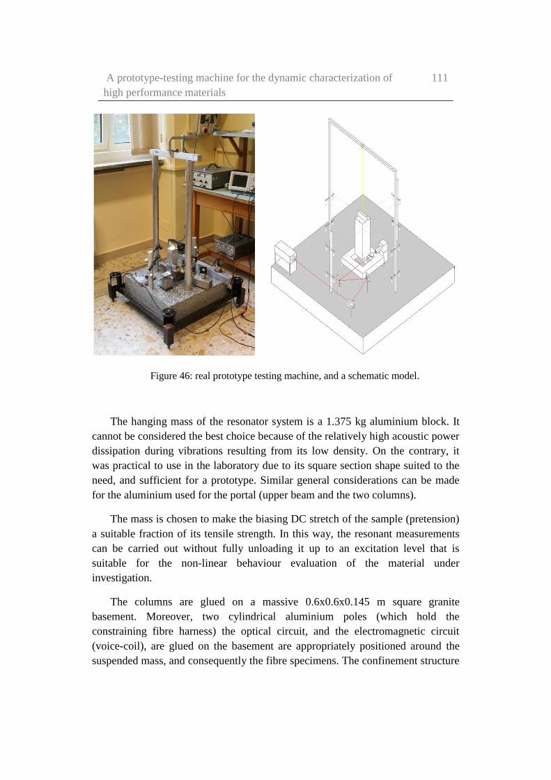
A prototype-testing machine for the dynamic characterization of
high performance materials
111
Figure 46: real prototype testing machine, and a schematic model.
The hanging mass of the resonator system is a 1.375 kg aluminium block. It
cannot be considered the best choice because of the relatively high acoustic power
dissipation during vibrations resulting from its low density. On the contrary, it
was practical to use in the laboratory due to its square section shape suited to the
need, and sufficient for a prototype. Similar general considerations can be made
for the aluminium used for the portal (upper beam and the two columns).
The mass is chosen to make the biasing DC stretch of the sample (pretension)
a suitable fraction of its tensile strength. In this way, the resonant measurements
can be carried out without fully unloading it up to an excitation level that is
suitable for the non-linear behaviour evaluation of the material under
investigation.
The columns are glued on a massive 0.6x0.6x0.145 m square granite
basement. Moreover, two cylindrical aluminium poles (which hold the
constraining fibre harness) the optical circuit, and the electromagnetic circuit
(voice-coil), are glued on the basement are appropriately positioned around the
suspended mass, and consequently the fibre specimens. The confinement structure
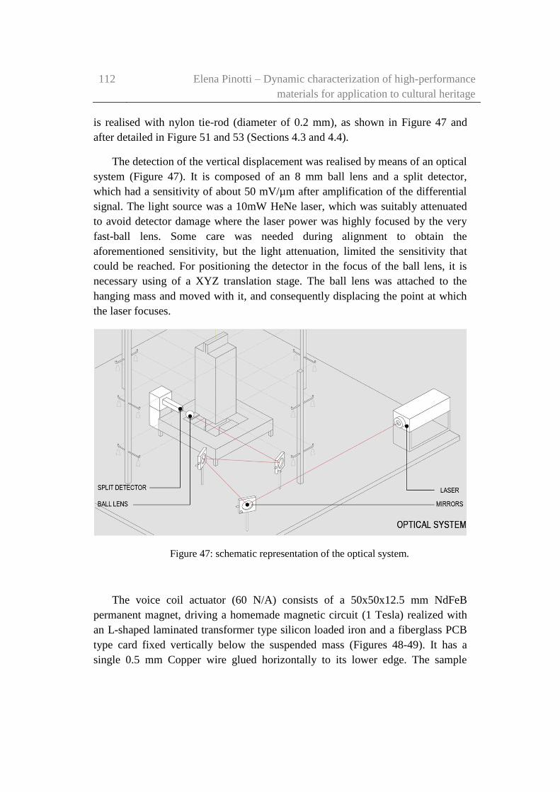
112 Elena Pinotti – Dynamic characterization of high-performance
materials for application to cultural heritage
is realised with nylon tie-rod (diameter of 0.2 mm), as shown in Figure 47 and
after detailed in Figure 51 and 53 (Sections 4.3 and 4.4).
The detection of the vertical displacement was realised by means of an optical
system (Figure 47). It is composed of an 8 mm ball lens and a split detector,
which had a sensitivity of about 50 mV/µm after amplification of the differential
signal. The light source was a 10mW HeNe laser, which was suitably attenuated
to avoid detector damage where the laser power was highly focused by the very
fast-ball lens. Some care was needed during alignment to obtain the
aforementioned sensitivity, but the light attenuation, limited the sensitivity that
could be reached. For positioning the detector in the focus of the ball lens, it is
necessary using of a XYZ translation stage. The ball lens was attached to the
hanging mass and moved with it, and consequently displacing the point at which
the laser focuses.
Figure 47: schematic representation of the optical system.
The voice coil actuator (60 N/A) consists of a 50x50x12.5 mm NdFeB
permanent magnet, driving a homemade magnetic circuit (1 Tesla) realized with
an L-shaped laminated transformer type silicon loaded iron and a fiberglass PCB
type card fixed vertically below the suspended mass (Figures 48-49). It has a
single 0.5 mm Copper wire glued horizontally to its lower edge. The sample

A prototype-testing machine for the dynamic characterization of
high performance materials
113
length was adapted for positioning the conductor in the middle of the 8 mm air
gap of the magnetic circuit to position the wire in the centre of the magnet.
Figure 48: schematic representation of the electromagnetic system.
Figure 49: the homemade magnetic circuit.
The observed electronic noise was under 1 mV (20 nm) without averaging,
which is well below the environmental mechanical/seismic noise that instead
varied significantly throughout the day on the non-damped table. It is in all cases

114 Elena Pinotti – Dynamic characterization of high-performance
materials for application to cultural heritage
being the most important noise source. Averaging helped to reduce its effects, and
was adopted in adequate amounts when taking measurements.
The prototype-testing machine realised may be used for free-decay and forced
tests. In the free-decay tests, the ring-down of vertical oscillations is observed by
the detector, and digitally recorded after A/D conversion. In the forced tests, sine
wave excitation is provided through the voice coil by a function generator. The
amplitude and phase of the induced vertical oscillation sine wave are measured
with an oscilloscope or an AC digital voltmeter. The sine wave source, a function
generator, (AGILENT 3320 A, 50 Ω output) reaches, at 1µHz, 1 µHz resolution in
the range of interest. Given the 50 Ohm output resistance of the generator, the
short circuit output current of 200 mA peak-to-peak delivered at the maximum
peak-to-peak amplitude of 10 V is within the specified linear range. Nevertheless,
a check on distortion was run for safety before deciding to load directly the
generator with the low resistance voice coil.
4.3 The resonant spring-mass approach
During the tests for the evaluation of the mechanical properties of fibres or
yarn via a spring-mass approach (both static and dynamic tests), all single fibres
of the sample are subjected to the same tension at all times. The preload imposed
selecting a suspended mass it is very important, because may be used for the
selection of the operating point on the stress-strain curve. In addition, the
suspended mass guarantees that the fibres in the bundle never unload during an
oscillation cycle. In case of weak nonlinearities, the damping values obtained
from a single unwoven bundle are expected to be representative of the single fibre
behaviour. Highly accurate information of the relevant material properties can be
obtained directly from such measurements. No deconvolution is necessary and the
experimental conditions are well defined.
The resonance frequency is the parameter used for the suspension stiffness,
and consequently the elastic modulus E of the material. However, it is possible
only if both the number and the diameter of the fibres are known. To evaluate the
resonant frequency with high accuracy is necessary introducing an appropriate
containment structure, for reducing the system disturbances. In this work, the
movement of the mass was reduced to a single vertical degree of freedom by
means of a confinement structure (realised by means of a web of fibre called “tie-
rods”) that minimizing their contributions to both resonance frequency and losses.

A prototype-testing machine for the dynamic characterization of
high performance materials
115
The principles of operation of the confinement structure of the prototype-
testing machine developed are described in detail because they are a fundamental
aspect of the proposed approach. The basic idea is to take advantage of the cosine
law to minimize the stretching imposed on the tie-rods, when a mass oscillates
along the vertical direction. The tie-rods are fixed to the mass horizontally (Figure
50), to constrain lateral displacements, but to allow only the vertical ones.
Figure 50: Schematic arrangement of tie-rods, with attachment errors.
A useful additional stiffness 𝑘𝑡𝑧 is introduced by the application of the n tie-
rods to vertical oscillations. However, the additional stiffness is reduced in such a
scheme, by the strain 𝜀𝑡𝑜 produced in the tie-rods due to pre-tension when they are
horizontal, plus half the square of their inclination angle ϑ. This relation is
expressed by the following equation (1). It can be easily obtained from the
analysis of the schematic representation show in Figure 50
𝑘𝑡𝑧 ≈ 𝑛𝑘𝑡 (1
2𝜃2 + 𝜀𝑡0) (1)
The lateral stiffness to horizontal movements of the mass is given by
𝑛𝑘𝑡 2 ⁄ for each orthogonal direction. Careful alignment, suitable choice of
material and the imposed tension play the key role in the optimisation of the
confinement structure's performance. The lateral stiffness must be high. In this

116 Elena Pinotti – Dynamic characterization of high-performance
materials for application to cultural heritage
way, the pendulum mode frequency is much higher compared to the vertical
spring-mass mode frequency of interest for this work. Instead, the vertical
stiffness contribution from the confinement structure must be low, in order to
minimize the effect on resonance frequency and damping. As discussed below, it
is easier to guarantee this condition for a multifilament bundle than for a single
fibre. For the same reason, measurements on the single fibres should be avoided
in the first phase of development.
The practical realization and the mechanism chosen to fix the tie-rods’ tension
of the confinement structure in the prototype-testing machine is shown in Figure
51. The mechanism is constituted by sixteen 0.13 kg bolts, suspended at each end
of a tie-rod beyond a pulley fixed on a post similar to the Atwood machine. Once
all pulleys are carefully placed on the table at the same height and the tie-rods
glued to the mass only after all components are at rest, the residual long term
creep in the tested fibres can produce meaningful values of the angle θ in equation
(1). It is possible to expect to remain below a couple of milliradians. As a result,
the contribution to the stiffness is unimportant as compared to the effect of strain.
In a similar way, negligible effect on stiffness, and consequently on the resonance
frequency, are expected to be caused by small dynamic variation of θ. This is
valid only if the non-linearity, introduced by the tie-rods, is counterbalanced with
the assessment of the non-linearity of the tested sample.
Figure 51: Significant components in the prototype machine.
It is worth to underline that, during the mass's oscillation, the maximum value
of the dynamic angle θ in equation (1) is evaluated as a ratio between the
oscillation amplitude and the tie-rods’ length. For some fibres, this condition can
require a minimum length for the tie-rods and/or impose limits on the excitation
level when the constraints on the confinement structure disturbance are critical.

A prototype-testing machine for the dynamic characterization of
high performance materials
117
The oscillation amplitude itself should be fixed at a fraction (e.g. 20%) of the
static pretension imposed by the weight of the suspended mass, in order to
guarantee that unloading does not occur. This level could reach approximately the
20% of the fibre strength. This value corresponds to the maximum admissible
strain, of which the amplitude is limited within a few percent. It is typically about
10-3 for high strength fibres, which suggests rms strains below 10-4 for the
oscillation term. The strain variation entails for the suspended mass an rms
amplitude with values ranging from below 10 µm to above 100 µm, for samples
of a few centimetres and a couple of meters, respectively. It depends very much
on the length of the fibre sample under testing. This, in turn, calls for high
sensitivity of the vibration detector that was designed to provide a sensitivity,
which was well below a micrometre. To overcome these issues, and the
requirement for low disturbance, which suggested the use of a non-contact
detector, an optical position sensor was employed. Interferometry was excluded
due to the limited analogue range, which it grants and the quiet mechanical
environment that it necessitates. A focused light approach was used, as illustrated
in the following, which yields a sensitivity below 10 nm in the sine-wave mode
without narrow-banding.
The methods chosen for non-contact excitation and detection are shown
schematically in Figure 52. A voice coil (also observable in Figure 48) introduces
the vertical forcing tension term. A ball lens glued to the suspended mass focuses
a laser beam onto a split detector that is used for detecting the position. These
elements should be taken into account for the minimization of disturbances that
could be otherwise introduced by both functions.
The resonance frequencies expected are low enough for high-strength low-
damping fibres because of their stiffness. In fact, the resonance angular frequency
𝜔0 may be expressed in the following form (eq. 2)
𝜔0 = √𝑔
𝐿𝜀𝑀=
𝜔𝑝
√𝜀𝑀
(2)
where 𝜔𝑝 is the free pendulum frequency and εM is the fibre strain under the
static pre-tension. It is induced by the weight of the suspended mass.
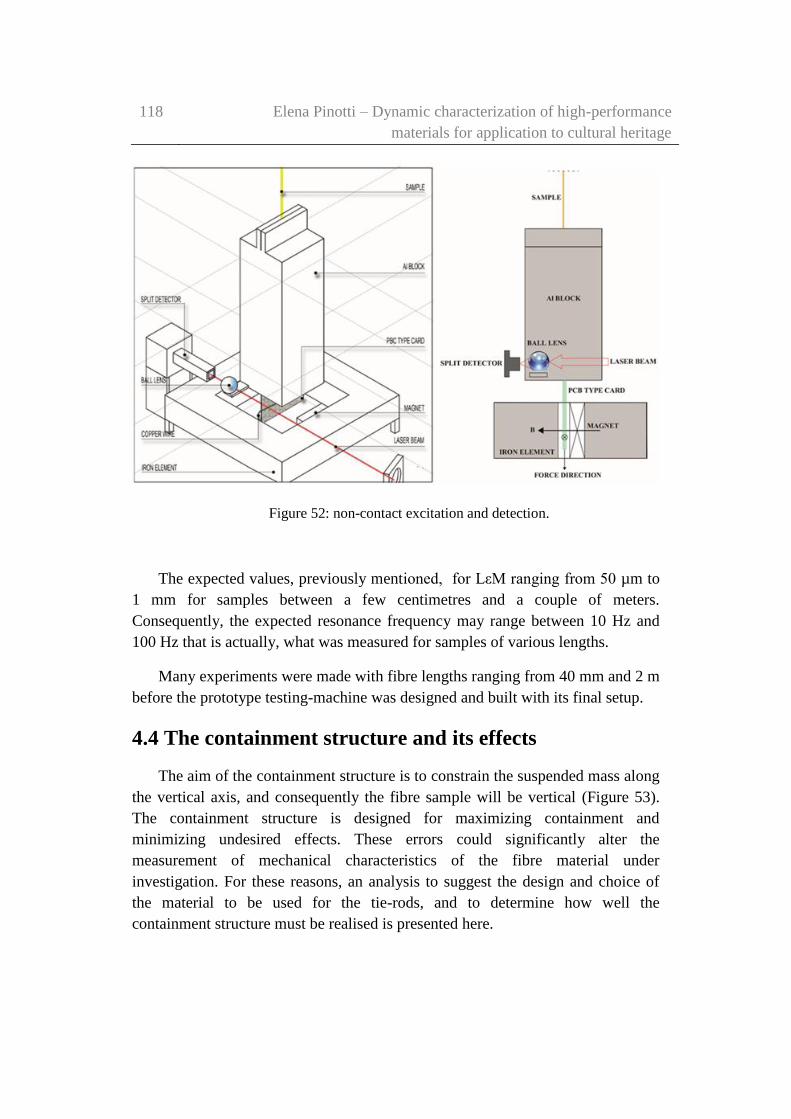
118 Elena Pinotti – Dynamic characterization of high-performance
materials for application to cultural heritage
Figure 52: non-contact excitation and detection.
The expected values, previously mentioned, for LεM ranging from 50 µm to
1 mm for samples between a few centimetres and a couple of meters.
Consequently, the expected resonance frequency may range between 10 Hz and
100 Hz that is actually, what was measured for samples of various lengths.
Many experiments were made with fibre lengths ranging from 40 mm and 2 m
before the prototype testing-machine was designed and built with its final setup.
4.4 The containment structure and its effects
The aim of the containment structure is to constrain the suspended mass along
the vertical axis, and consequently the fibre sample will be vertical (Figure 53).
The containment structure is designed for maximizing containment and
minimizing undesired effects. These errors could significantly alter the
measurement of mechanical characteristics of the fibre material under
investigation. For these reasons, an analysis to suggest the design and choice of
the material to be used for the tie-rods, and to determine how well the
containment structure must be realised is presented here.
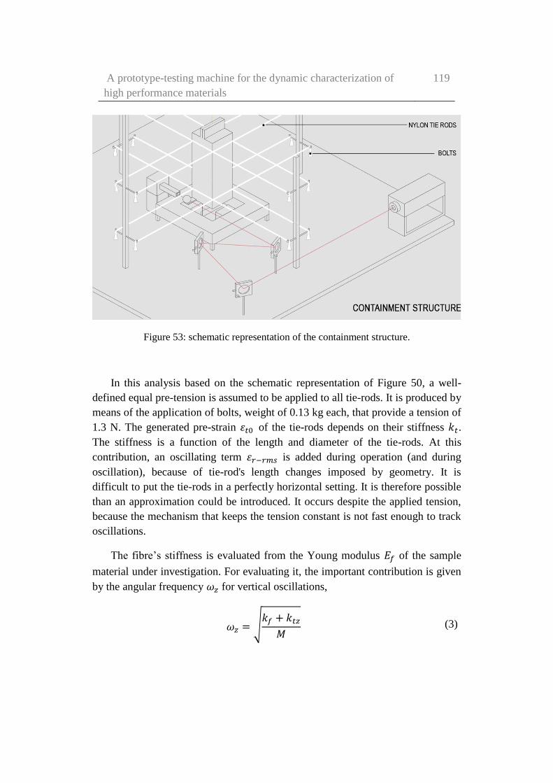
A prototype-testing machine for the dynamic characterization of
high performance materials
119
Figure 53: schematic representation of the containment structure.
In this analysis based on the schematic representation of Figure 50, a well-
defined equal pre-tension is assumed to be applied to all tie-rods. It is produced by
means of the application of bolts, weight of 0.13 kg each, that provide a tension of
1.3 N. The generated pre-strain 𝜀𝑡0 of the tie-rods depends on their stiffness 𝑘𝑡.
The stiffness is a function of the length and diameter of the tie-rods. At this
contribution, an oscillating term 𝜀𝑟−𝑟𝑚𝑠 is added during operation (and during
oscillation), because of tie-rod's length changes imposed by geometry. It is
difficult to put the tie-rods in a perfectly horizontal setting. It is therefore possible
than an approximation could be introduced. It occurs despite the applied tension,
because the mechanism that keeps the tension constant is not fast enough to track
oscillations.
The fibre’s stiffness is evaluated from the Young modulus 𝐸𝑓 of the sample
material under investigation. For evaluating it, the important contribution is given
by the angular frequency 𝜔𝑧 for vertical oscillations,
𝜔𝑧 = √𝑘𝑓 + 𝑘𝑡𝑧
𝑀 (3)

120 Elena Pinotti – Dynamic characterization of high-performance
materials for application to cultural heritage
Its fractional variation induced by the tie-rods containment structure may be
written as
∆𝜔𝑧
𝜔𝑧=
𝑛
2
𝑘𝑡
𝑘𝑓𝜀𝑡0 (4)
when taking into account the tie-rod’s stiffness (eq. (1)) and considering its
contribution to the vertical stiffness, the contribution is mainly given by their pre-
tension. To obtain an accuracy better than 0.1% of the stiffness, it is possible seen
from equation (4) that the elastic modulus of the tie-rods must be 10 times smaller
respect to the sample material, for a pre-strain of 3x10⁻⁴. The tie-rods used in this
prototype-testing machine have roughly the same diameter and one-fourth the
length of the sample under investigation. For this reason, the material chosen for
the tie-rods was Nylon. Its Young modulus is about 6 GPa, respect to 80 GPa that
is expected for the elastic modulus of a para-aramid material, for example. The
tie-rods’ length and diameter were chosen to be 0.17 m and 0.18 mm,
respectively. According to equation (4), it is worth pointing out that, as previously
affirmed, it would be easier to minimise the effects on confinement structure in
the measurement of vertical stiffness testing multifilament fibres than single fibre.
Indeed, the tie-rod's stiffness is proportional to the number of fibres and this
imposes the use of single fibres as tie-rods. Variations in temperature can be
minimised as Nylon thermal expansion coefficient is 7.2·10-5/K; in this case, even
an excursion of 14 K would only produce an increment of 0.1% on the static strain
𝜀𝑡0. The Nylon confinement structure, as explained in equation (4), increases its
resonance frequency by 0.2%. It was deemed acceptable, and temperature
variations are therefore expected to affect the sixth decimal, which is
insignificant.
It is important to pay attention to the non-linear contribution introduced by
equation (1), the oscillating part of θ angle that has to be added to the static angle.
The additional contribution introduces a third order coefficient to the system
stiffness, which does not belong to the sample of fibres under testing.
Consequently, it represents an error contribution into the evaluation of the non-
linearity of the sample. All tested fibres showed a softening non-linearity (a
negative third order coefficient; on the other hand, this dynamic contribution was
positive (hardening non-linearity). This result supports our confidence in the
capability to measure the non-linear behaviour of high-strength fibres.

A prototype-testing machine for the dynamic characterization of
high performance materials
121
4.5 Quality Factor limitations
The quality factor Q is used for the characterization of the resonator and its
losses, as is a common practice in measurements of forced oscillation. The quality
factor is experimentally obtained as the ratio between the resonance frequency ν
and full 3 dB width Δν of the amplitude response to excitation:
Q=ν/Δν (5)
It is usually measured as the frequency difference between the two ± 45°
phase shift points on both side of the resonance frequency. The quality factor is
strictly linked to the damping ratio 𝜁, (it is inversely proportional), and can be
expressed through the following relation
Q=1/2ζ (6)
The quality factor can also be written as
𝑄 = 𝜔𝑛
𝑊
𝑃𝑑= 2𝜋
𝑊
𝑊𝑑
(7)
where Pd is the average dissipated power, W is the energy stored in the
resonator and Wd is the energy lost during each cycle.
Many sources of mechanical energy dissipation contribute to the limitation of
Q in a spring-mass system. The aim of this section is to analyse all sources and
their contributions, in order to evaluate how well the measured quality factor
represents the intrinsic one of the fibre sample. The contributions taken into
consideration in this work are:
the energy dissipation in the tie-rods of the confinement structure (Qt)
the acoustic radiation (Qa),
the dissipation in the equipment producing the forcing term in the
forced oscillation technique (Qe).
The measured quality factor can be evaluated as the combination of Q
limitations. Each limitation can be ascribed to one of these mechanisms,
appearing as the measured value if the represented power losses were the only

122 Elena Pinotti – Dynamic characterization of high-performance
materials for application to cultural heritage
contribution to system dissipation. The limitations taken into consideration and
their combination can be expressed through the following equation
1
𝑄=
1
𝑄𝑓+
1
𝑄𝑡+
1
𝑄𝑎+
1
𝑄𝑒 (8)
The comparison between tie-rods’ contribution and the dissipation in the fibre
samples could be done because both are generated by the same mechanism.
Indeed, during the oscillation of the spring-mass system, the change in strain
varies periodically in both tie-rods and fibres under test. In this way, the energy
stored in the system is converted backward and forward between kinetic energy
stored in the mass and elastic energy stored in the fibres. As a result, a part of the
converted energy is lost into heat process. The lost power is proportional to the
one converted by the damping ratio ζ. In the same way, the energy 𝑊𝑑 is
dissipated in a full cycle. However, the elastic energy stored at any time in a
stretched string can be expressed as
𝑊 =1
2𝐸𝐴𝑙𝜀2 (9)
The ratio between one-cycle dissipation in the 16 tie-rods (𝑊𝑑𝑡) and in the
fibres under test (𝑊𝑑𝑓), may be written as
𝑊𝑑𝑡
𝑊𝑑𝑓= 16
𝜁𝑡
𝜁𝑓
𝐸𝑡
𝐸𝑓
𝐴𝑡
𝐴𝑓
𝑎
𝐿
𝜀𝑡𝑟𝑚𝑠2
𝜀𝑓𝑟𝑚𝑠2 (10)
The actual values of the final setup, namely 𝐸𝑡/𝐸𝑓 ≈ 0.1, 𝐴𝑡/𝐴𝑓 ≈ 1, 𝑎/𝐿 ≈
0.25, and 𝜁𝑡 ≈ 0.02 are separately measured with the same machine. By
introducing these values in equation (10) it appears clear how, due to a dissipation
error in the confinement structure smaller than 0.5%, in the measurement of
Qf (for the extreme case of Qf ≈ 103), the dynamic rms strain ratio between tie-
rods and fibre bundle must be smaller than 0.014. This condition is satisfied if the
tie-rods are perfectly horizontal, as in that case
𝜀𝑡𝑟𝑚𝑠 =1
2𝜀𝑓𝑟𝑚𝑠
2 (𝐿
𝑎)
2
(11)

A prototype-testing machine for the dynamic characterization of
high performance materials
123
It imposes an easy 𝜀𝑓𝑟𝑚𝑠 < 1.4 ∙ 10−3 to reach the desired limit in the error of
the quality factor. On the contrary, it is difficult to achieve such a limit if the tie-
rods are not perfectly horizontal, but inclined by angle 𝜃0. In this second case:
𝜀𝑡𝑟𝑚𝑠
𝜀𝑓𝑟𝑚𝑠= 𝜃0
𝐿
𝑎 (12)
And, consequently, it must be 𝜃0 < 3.5 ∙ 10−3. It means that the maximum
acceptable vertical misalignment is 0.5 mm. To conclude, great attention should
be put into containment structure setup, in order to obtain a configuration where
the dissipation in the tie-rods do not affect excessively Qf measurement.
The next contribution to power loss during oscillation, taken into
consideration, is the acoustic radiation from the upper and lower faces of the
vibrating mass. It is considered as a sound wave propagates away from them.
Since in that case the amplitudes of oscillation and the velocities are very small,
the power of the acoustic radiation may be calculated by the following equation
𝑃𝑑,𝑎 = 2𝜚0𝑐𝑆𝑢𝑟𝑚𝑠2 𝜎𝑟𝑎𝑑 (13)
in which 𝜚0 is the air density, c the speed of sound, S the front surface of the
vibrating body, 𝑢𝑟𝑚𝑠 the rms velocity of the radiating surfaces, and finally 𝜎𝑟𝑎𝑑
the radiation efficiency. It depends on the frequency and on radiator shape and is
considered to be as small as 0.01 for this specific case, mainly because of the low
20 Hz frequency (Allard & Champoux, 1992) (Dahl, et al., 1987) (Larko &
Cotoni, 2007).
In this method, the radiated acoustic power is proportional to the square of
rms displacement, and the same is for the stored energy. It means that the system
Q limitation introduced by this mechanism is independent of the oscillation
amplitude. This limit is about 104 in the experimental testing machine, which
implies an error of -10% if Qf is on the order of 1000. The reduction of S, can be
obtained by using a slimmer and denser mass. This alternative should introduce a
simple improvement. An example could be the use of a longer and lighter
tungsten mass. In this way is possible to reach a reduction by a factor of 10 of the
cross section S, and guarantee also an error below 1% on 𝑄𝑓. About power
dissipation in the excitation circuit, the physical mechanism is Joule heating. In
fact, the vibration induced e.m.f. dissipates power on the output resistance of the

124 Elena Pinotti – Dynamic characterization of high-performance
materials for application to cultural heritage
electrical circuit which drives a current into the actuator voice coil, namely the
negligible conductor resistance and the relevant 50 Ω output resistance R0 of the
signal generator. Such dissipated electrical power can be written as
𝑃𝑑𝑒 =𝐵2𝑙2𝑢𝑟𝑚𝑠
2
𝑅0 (14)
where B is the magnetic induction in the magnet gap and l is the length of the
exposed Copper wire. To evaluate how much this effect influences the measured
quality factor, the power dissipation in the excitation circuit must be compared
with the input power required to maintain oscillation (Pin=Pd). The input power is
given by:
𝑃𝑖𝑛 = 𝐵𝑙𝐼𝑟𝑚𝑠𝑢𝑟𝑚𝑠 (15)
where Irms is the rms current driven into the voice coil, and since
𝑢𝑟𝑚𝑠 = 𝜔𝑛𝑄𝐵𝑙𝐼𝑟𝑚𝑠
𝑘𝑓 (16)
by considering that Pin/Pde = Qe/Q it can be easily seen that
𝑄𝑒 =𝑅0√𝑘𝑀
𝐵2𝑙2 (17)
In the last equation, the term √𝑘𝑀 represents the characteristic mechanical
impedance of the resonator. A simple calculation of this Q limitation yields 𝑄𝑒 ≈
4 ∙ 105 for the prototype-testing machine that means that the error introduced by
this mechanism in the evaluation of Qf is about -0.2% in the case of a fibre with Qf
=1000. Clearly, a dramatic improvement could be readily introduced by adopting
a current source with high output impedance to drive the current into the voice
coil, instead of the signal generator at hand. A simple improvement can be made
by interfacing the signal generator to the voice coil via a suitable driver stage that
could be a series resistor.

A prototype-testing machine for the dynamic characterization of
high performance materials
125
126 Elena Pinotti – Dynamic characterization of high-performance
materials for application to cultural heritage
Chapter 5
Experimental investigation on
high-strength fibres and results
This Chapter presents the experimental investigation and the results obtained
with the prototype testing machine in its final setup configuration. The
experimental investigation consisted in the dynamic characterization of high-
strength fibres, by means of simple non-destructive non-linearity tests (forced
tests). The results could be used in the near future as an alternative to traditional
methods currently used for assessing damage, defects and malfunctions in high-
strength fibres and elements (Mininni, et al., 2016).
During the forced tests, the fibres sample was excited by means of a
sinusoidal low intensity force, and the response, in term of strain as a function of
frequency and input amplitude, was recorded. The results are used to evaluate, the
damping from the quality factor measurement, and finally the non-linearity index
by means of the analysis of the “backbone curve”, function of the resonant
frequency and input amplitude.
The idea is to associate weak non-linearity of the material, as detected in the
dynamic response to forced tests, as an indicator used in safety and lifecycle
assessment. For the high-strength tested materials, the cubic stiffness coefficient 𝜒

Experimental investigation on high-strength fibres and results 127
of an equivalent Duffing oscillator was chosen for representing an indicator of
weak nonlinear behaviour.
Samples of high-strength material, such as carbon, para-aramid (Kevlar® 29),
and silicon carbide (SiC), were tested initially in pristine condition. In a second
phase, Kevlar® 29 samples were subjected to UV rays and tested (Chapter 6).
Part of the work described in this chapter has also been published in
Experimental Mechanics (Ceravolo, et al., 2017).
5.1 Experimental investigation on pristine samples
The dynamic response of a system can be analysed in different ways. Forced
oscillations at resonance tests were carried out on pristine high-strength material,
and in a second phase on damaged Kevlar® 29 fibres (Chapter 6).
To perform dynamic tests, it was necessary to realise a vibrating system, and
the prototype-testing machine was previously described in Chapter 4. The
suspended 1.375 kg aluminium block had the role of the mass in a mass-spring
resonator. Such mass is designed to keep the sample in tension, usually a few
percent of its tensile strength. In this way, the resonant measurements may be
carried out without fully unloading the sample under investigation.

128 Elena Pinotti – Dynamic characterization of high-performance
materials for application to cultural heritage
5.1.1 Samples investigated
As previously mentioned in the introduction, three different materials were
investigated: SiC, Kevlar® 29, and carbon. Their main characteristics are shortly
listed hereinafter in Table 8.
The SiC (Type S) specimen tested (Figure
54), had a length of 0.66 m and consisted
of 500 parallel single fibres with a
diameter of 14 μm each, and
consequently, a cross sectional area of
0.0565 mm2. His colour is black, typical
for ceramic materials. The elastic
modulus of the fibre was about 270 GPa
and the linear density was about 3000
kg/m3.
The Kevlar® 29 samples tested was
provided from S.I.G.I.T. snc company
(S.I.G.I.T., 2015), making high-tech
materials for the glass-industry. It is a
para-aramid material, realised with
filaments of DuPont production with
100% purity. The yarn is yellow, and is
manufactured in the form of continuous
filament (Figure 55). In other words,
various filaments of infinite theoretical
length form it, with a diameters ranging
from 10 μm to 15 μm, positioned one
beside the other until obtaining the desired thread count (2500 dTex, in this case).
For what concerns the Kevlar® 29 specimen tested, it had a length of 0.66 m. It
was a rope consisted of about 2000 single fibres with a diameter of 12 μm each
and the cross-sectional area is of 0.174 mm². The elastic modulus of the sample
was about 80 GPa, whilst the linear density was about 1440 kg/m³.
Figure 55: Kevlar® 29 sample tested.
Figure 54: the SiC (Type S) sample tested.
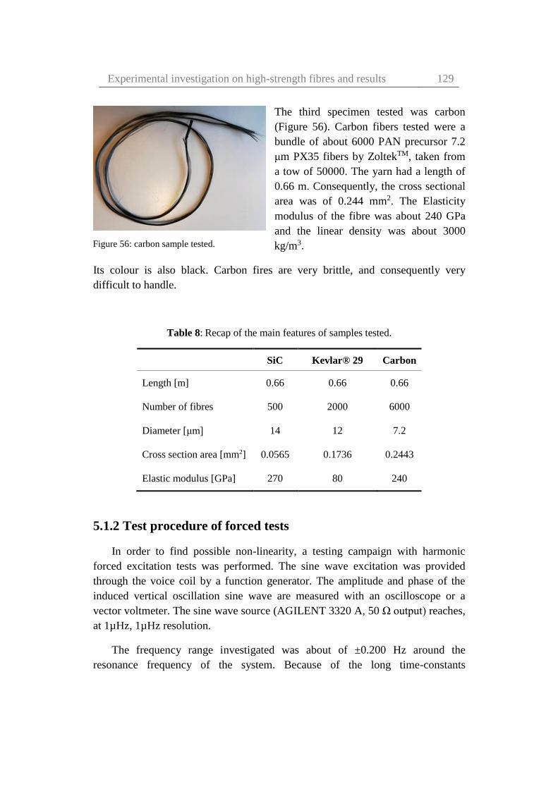
Experimental investigation on high-strength fibres and results 129
The third specimen tested was carbon
(Figure 56). Carbon fibers tested were a
bundle of about 6000 PAN precursor 7.2
μm PX35 fibers by ZoltekTM, taken from
a tow of 50000. The yarn had a length of
0.66 m. Consequently, the cross sectional
area was of 0.244 mm2. The Elasticity
modulus of the fibre was about 240 GPa
and the linear density was about 3000
kg/m3.
Its colour is also black. Carbon fires are very brittle, and consequently very
difficult to handle.
Table 8: Recap of the main features of samples tested.
SiC Kevlar® 29 Carbon
Length [m] 0.66 0.66 0.66
Number of fibres 500 2000 6000
Diameter [μm] 14 12 7.2
Cross section area [mm2] 0.0565 0.1736 0.2443
Elastic modulus [GPa] 270 80 240
5.1.2 Test procedure of forced tests
In order to find possible non-linearity, a testing campaign with harmonic
forced excitation tests was performed. The sine wave excitation was provided
through the voice coil by a function generator. The amplitude and phase of the
induced vertical oscillation sine wave are measured with an oscilloscope or a
vector voltmeter. The sine wave source (AGILENT 3320 A, 50 Ω output) reaches,
at 1µHz, 1µHz resolution.
The frequency range investigated was about of ±0.200 Hz around the
resonance frequency of the system. Because of the long time-constants
Figure 56: carbon sample tested.

130 Elena Pinotti – Dynamic characterization of high-performance
materials for application to cultural heritage
determined by high Q values at low frequencies, the sweep-sine approach was
avoided in favour of measuring the steady-state response with discrete steps of 5
or 10 mHz in relation to material sample under test, while keeping the force
constant. Then the test was repeated with different levels of the driving force,
regulated by adjusting the current driven into the voice coil by the function
generator, in steps of 1 V (or 0.5 V) from 0.5 V to 10 V (from 40 mA to 200 mA)
peak-to-peak, corresponding to a maximum rms force range of about 3.5 mN and
0.35 mN steps.
Once the input voltage interval was defined, changing the frequency of the
driving force (via the function generator) it was possible to record the values of
the output voltage, from which the displacement can be determined by using the
detector sensitivity measured for each curve in DC during photodiode calibration
(the testing machine sensitivity).
In this way it is possible to draw, point by point, the frequency-strain curve,
useful for the subsequent nonlinear characterization.
In Figures 57-62, the results of the strain evaluated from values recorded are
shown for the three different samples of high-strength materials (Section 5.1.1).
Moreover, Tables 9-11 show the input amplitude investigated and the
corresponding strain evaluated at a precise frequency value.
The testing machine sensitivity measured is 150 mV/µm for silicon carbide
sample, 70 mV/µm for pristine Kevlar® 29 sample, and 150 mV/µm, for carbon
sample, respectively.
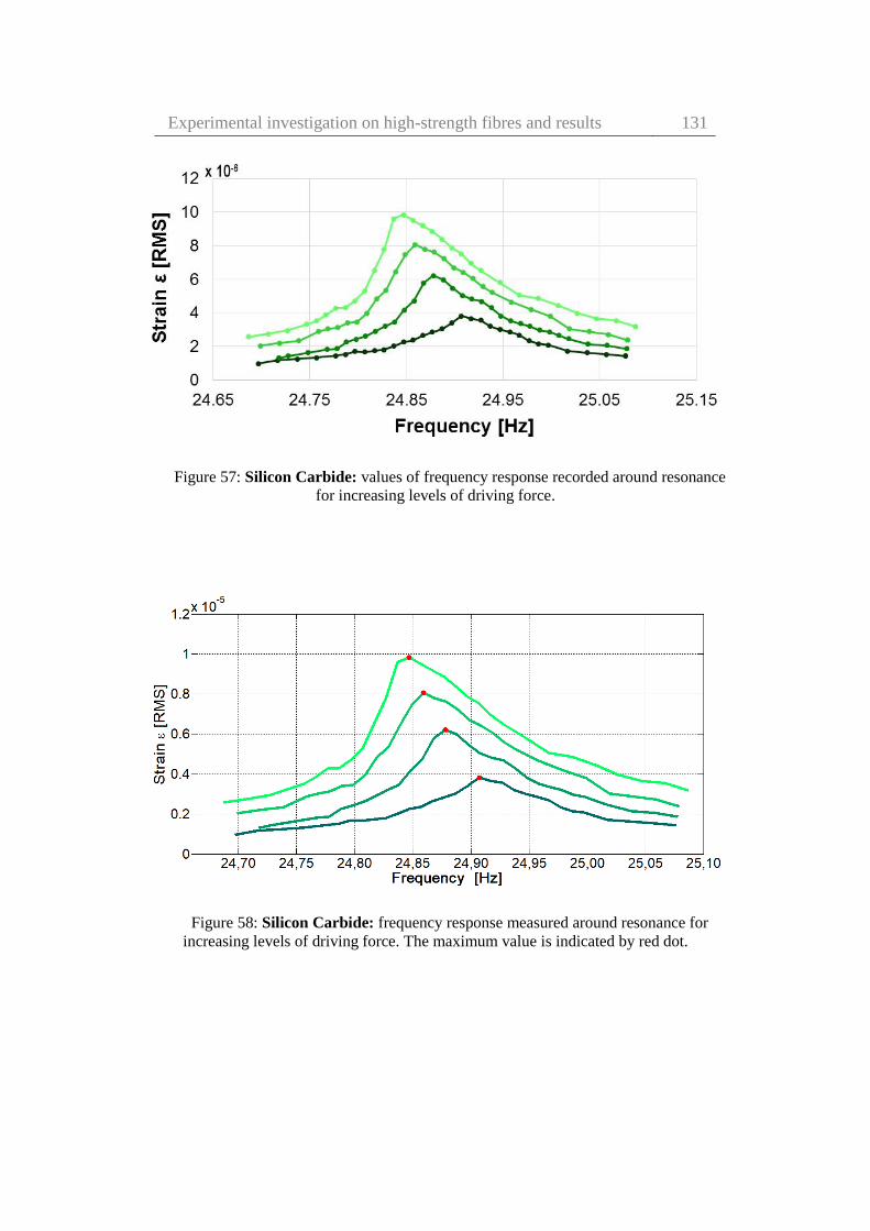
Experimental investigation on high-strength fibres and results 131
Figure 57: Silicon Carbide: values of frequency response recorded around resonance
for increasing levels of driving force.
Figure 58: Silicon Carbide: frequency response measured around resonance for
increasing levels of driving force. The maximum value is indicated by red dot.
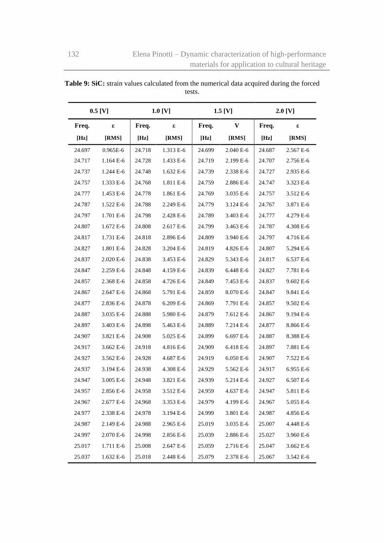
132 Elena Pinotti – Dynamic characterization of high-performance
materials for application to cultural heritage
Table 9: SiC: strain values calculated from the numerical data acquired during the forced
tests.
0.5 [V] 1.0 [V] 1.5 [V] 2.0 [V]
Freq. ε Freq. ε Freq. V Freq. ε
[Hz] [RMS] [Hz] [RMS] [Hz] [RMS] [Hz] [RMS]
24.697 0.965E-6 24.718 1.313 E-6 24.699 2.040 E-6 24.687 2.567 E-6
24.717 1.164 E-6 24.728 1.433 E-6 24.719 2.199 E-6 24.707 2.756 E-6
24.737 1.244 E-6 24.748 1.632 E-6 24.739 2.338 E-6 24.727 2.935 E-6
24.757 1.333 E-6 24.768 1.811 E-6 24.759 2.886 E-6 24.747 3.323 E-6
24.777 1.453 E-6 24.778 1.861 E-6 24.769 3.035 E-6 24.757 3.512 E-6
24.787 1.522 E-6 24.788 2.249 E-6 24.779 3.124 E-6 24.767 3.871 E-6
24.797 1.701 E-6 24.798 2.428 E-6 24.789 3.403 E-6 24.777 4.279 E-6
24.807 1.672 E-6 24.808 2.617 E-6 24.799 3.463 E-6 24.787 4.308 E-6
24.817 1.731 E-6 24.818 2.896 E-6 24.809 3.940 E-6 24.797 4.716 E-6
24.827 1.801 E-6 24.828 3.204 E-6 24.819 4.826 E-6 24.807 5.294 E-6
24.837 2.020 E-6 24.838 3.453 E-6 24.829 5.343 E-6 24.817 6.537 E-6
24.847 2.259 E-6 24.848 4.159 E-6 24.839 6.448 E-6 24.827 7.781 E-6
24.857 2.368 E-6 24.858 4.726 E-6 24.849 7.453 E-6 24.837 9.602 E-6
24.867 2.647 E-6 24.868 5.791 E-6 24.859 8.070 E-6 24.847 9.841 E-6
24.877 2.836 E-6 24.878 6.209 E-6 24.869 7.791 E-6 24.857 9.502 E-6
24.887 3.035 E-6 24.888 5.980 E-6 24.879 7.612 E-6 24.867 9.194 E-6
24.897 3.403 E-6 24.898 5.463 E-6 24.889 7.214 E-6 24.877 8.866 E-6
24.907 3.821 E-6 24.908 5.025 E-6 24.899 6.697 E-6 24.887 8.388 E-6
24.917 3.662 E-6 24.918 4.816 E-6 24.909 6.418 E-6 24.897 7.881 E-6
24.927 3.562 E-6 24.928 4.687 E-6 24.919 6.050 E-6 24.907 7.522 E-6
24.937 3.194 E-6 24.938 4.308 E-6 24.929 5.562 E-6 24.917 6.955 E-6
24.947 3.005 E-6 24.948 3.821 E-6 24.939 5.214 E-6 24.927 6.507 E-6
24.957 2.856 E-6 24.958 3.512 E-6 24.959 4.637 E-6 24.947 5.811 E-6
24.967 2.677 E-6 24.968 3.353 E-6 24.979 4.199 E-6 24.967 5.055 E-6
24.977 2.338 E-6 24.978 3.194 E-6 24.999 3.801 E-6 24.987 4.856 E-6
24.987 2.149 E-6 24.988 2.965 E-6 25.019 3.035 E-6 25.007 4.448 E-6
24.997 2.070 E-6 24.998 2.856 E-6 25.039 2.886 E-6 25.027 3.960 E-6
25.017 1.711 E-6 25.008 2.647 E-6 25.059 2.716 E-6 25.047 3.662 E-6
25.037 1.632 E-6 25.018 2.448 E-6 25.079 2.378 E-6 25.067 3.542 E-6

Experimental investigation on high-strength fibres and results 133
Figure 59: Kevlar® 29: values of frequency response recorded around resonance for
increasing levels of driving force.
Figure 60: Kevlar® 29: frequency response measured around resonance for
increasing levels of driving force. The maximum value is indicated by red dot.
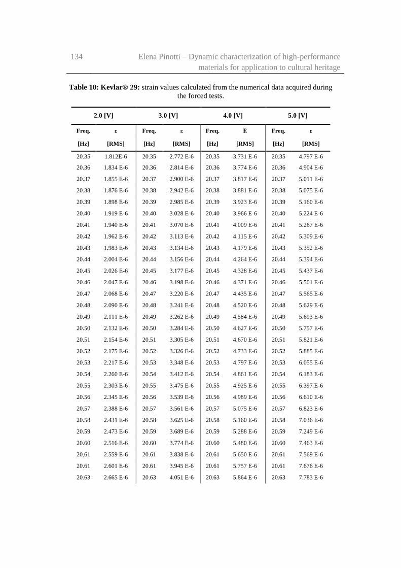
134 Elena Pinotti – Dynamic characterization of high-performance
materials for application to cultural heritage
Table 10: Kevlar® 29: strain values calculated from the numerical data acquired during
the forced tests.
2.0 [V] 3.0 [V] 4.0 [V] 5.0 [V]
Freq. ε Freq. ε Freq. Ε Freq. ε
[Hz] [RMS] [Hz] [RMS] [Hz] [RMS] [Hz] [RMS]
20.35 1.812E-6 20.35 2.772 E-6 20.35 3.731 E-6 20.35 4.797 E-6
20.36 1.834 E-6 20.36 2.814 E-6 20.36 3.774 E-6 20.36 4.904 E-6
20.37 1.855 E-6 20.37 2.900 E-6 20.37 3.817 E-6 20.37 5.011 E-6
20.38 1.876 E-6 20.38 2.942 E-6 20.38 3.881 E-6 20.38 5.075 E-6
20.39 1.898 E-6 20.39 2.985 E-6 20.39 3.923 E-6 20.39 5.160 E-6
20.40 1.919 E-6 20.40 3.028 E-6 20.40 3.966 E-6 20.40 5.224 E-6
20.41 1.940 E-6 20.41 3.070 E-6 20.41 4.009 E-6 20.41 5.267 E-6
20.42 1.962 E-6 20.42 3.113 E-6 20.42 4.115 E-6 20.42 5.309 E-6
20.43 1.983 E-6 20.43 3.134 E-6 20.43 4.179 E-6 20.43 5.352 E-6
20.44 2.004 E-6 20.44 3.156 E-6 20.44 4.264 E-6 20.44 5.394 E-6
20.45 2.026 E-6 20.45 3.177 E-6 20.45 4.328 E-6 20.45 5.437 E-6
20.46 2.047 E-6 20.46 3.198 E-6 20.46 4.371 E-6 20.46 5.501 E-6
20.47 2.068 E-6 20.47 3.220 E-6 20.47 4.435 E-6 20.47 5.565 E-6
20.48 2.090 E-6 20.48 3.241 E-6 20.48 4.520 E-6 20.48 5.629 E-6
20.49 2.111 E-6 20.49 3.262 E-6 20.49 4.584 E-6 20.49 5.693 E-6
20.50 2.132 E-6 20.50 3.284 E-6 20.50 4.627 E-6 20.50 5.757 E-6
20.51 2.154 E-6 20.51 3.305 E-6 20.51 4.670 E-6 20.51 5.821 E-6
20.52 2.175 E-6 20.52 3.326 E-6 20.52 4.733 E-6 20.52 5.885 E-6
20.53 2.217 E-6 20.53 3.348 E-6 20.53 4.797 E-6 20.53 6.055 E-6
20.54 2.260 E-6 20.54 3.412 E-6 20.54 4.861 E-6 20.54 6.183 E-6
20.55 2.303 E-6 20.55 3.475 E-6 20.55 4.925 E-6 20.55 6.397 E-6
20.56 2.345 E-6 20.56 3.539 E-6 20.56 4.989 E-6 20.56 6.610 E-6
20.57 2.388 E-6 20.57 3.561 E-6 20.57 5.075 E-6 20.57 6.823 E-6
20.58 2.431 E-6 20.58 3.625 E-6 20.58 5.160 E-6 20.58 7.036 E-6
20.59 2.473 E-6 20.59 3.689 E-6 20.59 5.288 E-6 20.59 7.249 E-6
20.60 2.516 E-6 20.60 3.774 E-6 20.60 5.480 E-6 20.60 7.463 E-6
20.61 2.559 E-6 20.61 3.838 E-6 20.61 5.650 E-6 20.61 7.569 E-6
20.61 2.601 E-6 20.61 3.945 E-6 20.61 5.757 E-6 20.61 7.676 E-6
20.63 2.665 E-6 20.63 4.051 E-6 20.63 5.864 E-6 20.63 7.783 E-6
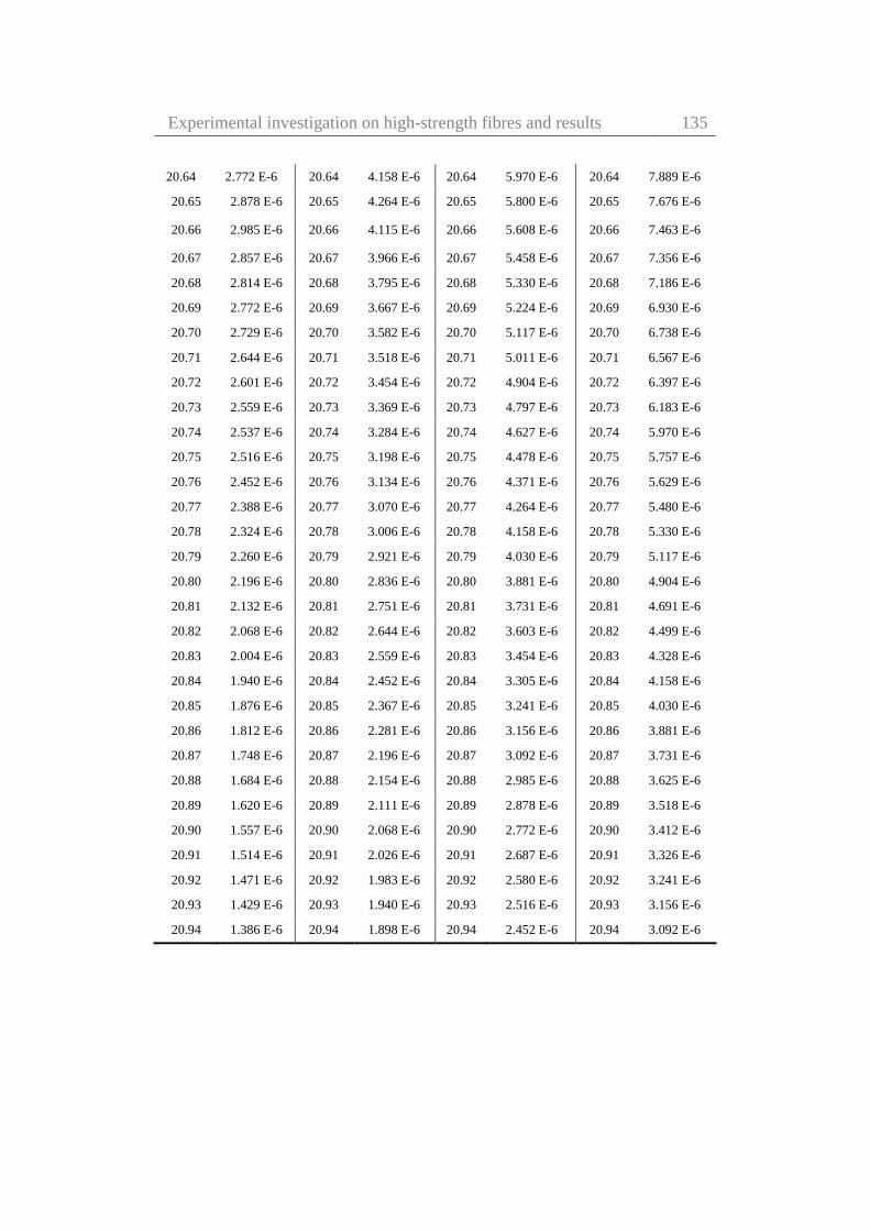
Experimental investigation on high-strength fibres and results 135
20.64 2.772 E-6 20.64 4.158 E-6 20.64 5.970 E-6 20.64 7.889 E-6
20.65 2.878 E-6 20.65 4.264 E-6 20.65 5.800 E-6 20.65 7.676 E-6
20.66 2.985 E-6 20.66 4.115 E-6 20.66 5.608 E-6 20.66 7.463 E-6
20.67 2.857 E-6 20.67 3.966 E-6 20.67 5.458 E-6 20.67 7.356 E-6
20.68 2.814 E-6 20.68 3.795 E-6 20.68 5.330 E-6 20.68 7.186 E-6
20.69 2.772 E-6 20.69 3.667 E-6 20.69 5.224 E-6 20.69 6.930 E-6
20.70 2.729 E-6 20.70 3.582 E-6 20.70 5.117 E-6 20.70 6.738 E-6
20.71 2.644 E-6 20.71 3.518 E-6 20.71 5.011 E-6 20.71 6.567 E-6
20.72 2.601 E-6 20.72 3.454 E-6 20.72 4.904 E-6 20.72 6.397 E-6
20.73 2.559 E-6 20.73 3.369 E-6 20.73 4.797 E-6 20.73 6.183 E-6
20.74 2.537 E-6 20.74 3.284 E-6 20.74 4.627 E-6 20.74 5.970 E-6
20.75 2.516 E-6 20.75 3.198 E-6 20.75 4.478 E-6 20.75 5.757 E-6
20.76 2.452 E-6 20.76 3.134 E-6 20.76 4.371 E-6 20.76 5.629 E-6
20.77 2.388 E-6 20.77 3.070 E-6 20.77 4.264 E-6 20.77 5.480 E-6
20.78 2.324 E-6 20.78 3.006 E-6 20.78 4.158 E-6 20.78 5.330 E-6
20.79 2.260 E-6 20.79 2.921 E-6 20.79 4.030 E-6 20.79 5.117 E-6
20.80 2.196 E-6 20.80 2.836 E-6 20.80 3.881 E-6 20.80 4.904 E-6
20.81 2.132 E-6 20.81 2.751 E-6 20.81 3.731 E-6 20.81 4.691 E-6
20.82 2.068 E-6 20.82 2.644 E-6 20.82 3.603 E-6 20.82 4.499 E-6
20.83 2.004 E-6 20.83 2.559 E-6 20.83 3.454 E-6 20.83 4.328 E-6
20.84 1.940 E-6 20.84 2.452 E-6 20.84 3.305 E-6 20.84 4.158 E-6
20.85 1.876 E-6 20.85 2.367 E-6 20.85 3.241 E-6 20.85 4.030 E-6
20.86 1.812 E-6 20.86 2.281 E-6 20.86 3.156 E-6 20.86 3.881 E-6
20.87 1.748 E-6 20.87 2.196 E-6 20.87 3.092 E-6 20.87 3.731 E-6
20.88 1.684 E-6 20.88 2.154 E-6 20.88 2.985 E-6 20.88 3.625 E-6
20.89 1.620 E-6 20.89 2.111 E-6 20.89 2.878 E-6 20.89 3.518 E-6
20.90 1.557 E-6 20.90 2.068 E-6 20.90 2.772 E-6 20.90 3.412 E-6
20.91 1.514 E-6 20.91 2.026 E-6 20.91 2.687 E-6 20.91 3.326 E-6
20.92 1.471 E-6 20.92 1.983 E-6 20.92 2.580 E-6 20.92 3.241 E-6
20.93 1.429 E-6 20.93 1.940 E-6 20.93 2.516 E-6 20.93 3.156 E-6
20.94 1.386 E-6 20.94 1.898 E-6 20.94 2.452 E-6 20.94 3.092 E-6

136 Elena Pinotti – Dynamic characterization of high-performance
materials for application to cultural heritage
6.0 [V] 7.0 [V] 8.0 [V] 9.0 [V] 10.0 [V]
Freq. ε Freq. ε Freq. ε Freq. ε Freq. ε
[Hz] [RMS] [Hz] [RMS] [Hz] [RMS] [Hz] [RMS] [Hz] [RMS]
20.35 5.76E-6 20.35 6.61E-6 20.35 7.29E-6 20.35 8.21E-6 20.35 9.81E-6
20.36 5.86E-6 20.36 6.72E-6 20.36 7.36E-6 20.36 8.32E-6 20.36 9.92E-6
20.37 5.97E-6 20.37 6.82E-6 20.37 7.42E-6 20.37 8.42E-6 20.37 10.02E-6
20.38 6.08E-6 20.38 6.93E-6 20.38 7.51E-6 20.38 8.53E-6 20.38 10.13E-6
20.39 6.18E-6 20.39 7.02E-6 20.39 7.57E-6 20.39 8.63E-6 20.39 10.24E-6
20.40 6.29E-6 20.40 7.10E-6 20.40 7.72E-6 20.40 8.74E-6 20.40 10.45E-6
20.41 6.35E-6 20.41 7.19E-6 20.41 7.87E-6 20.41 8.91E-6 20.41 10.66E-6
20.42 6.42E-6 20.42 7.27E-6 20.42 7.99E-6 20.42 9.08E-6 20.42 10.87E-6
20.43 6.50E-6 20.43 7.36E-6 20.43 8.14E-6 20.43 9.27E-6 20.43 11.09E-6
20.44 6.57E-6 20.44 7.46E-6 20.44 8.29E-6 20.44 9.45E-6 20.44 11.30E-6
20.45 6.63E-6 20.45 7.57E-6 20.45 8.42E-6 20.45 9.62E-6 20.45 11.51E-6
20.46 6.72E-6 20.46 7.68E-6 20.46 8.64E-6 20.46 9.81E-6 20.46 11.73E-6
20.47 6.78E-6 20.47 7.78E-6 20.47 8.85E-6 20.47 10.19E-6 20.47 12.05E-6
20.48 6.84E-6 20.48 7.89E-6 20.48 9.06E-6 20.48 10.58E-6 20.48 12.37E-6
20.49 6.93E-6 20.49 8.10E-6 20.49 9.38E-6 20.49 10.98E-6 20.49 12.69E-6
20.50 7.08E-6 20.50 8.21E-6 20.50 9.70E-6 20.50 11.26E-6 20.50 13.01E-6
20.51 7.23E-6 20.51 8.32E-6 20.51 9.92E-6 20.51 11.64E-6 20.51 13.43E-6
20.52 7.36E-6 20.52 8.53E-6 20.52 10.19E-6 20.52 12.15E-6 20.52 13.75E-6
20.53 7.57E-6 20.53 8.74E-6 20.53 10.59E-6 20.53 12.63E-6 20.53 14.18E-6
20.54 7.78E-6 20.54 8.96E-6 20.54 11.05E-6 20.54 13.11E-6 20.54 14.61E-6
20.55 7.80E-6 20.55 9.17E-6 20.55 11.34E-6 20.55 13.43E-6 20.55 15.14E-6
20.56 8.32E-6 20.56 9.49E-6 20.56 11.62E-6 20.56 13.73E-6 20.56 15.56E-6
20.57 8.64E-6 20.57 9.81E-6 20.57 11.94E-6 20.57 14.18E-6 20.57 16.21E-6
20.58 8.95E-6 20.58 10.13E-6 20.58 12.26E-6 20.58 14.49E-6 20.58 16.84E-6
20.59 9.17E-6 20.59 10.34E-6 20.59 12.47E-6 20.59 14.71E-6 20.59 17.27E-6
20.60 9.38E-6 20.60 10.66E-6 20.60 12.69E-6 20.60 14.96E-6 20.60 17.69E-6
20.61 9.49E-6 20.61 10.87E-6 20.61 12.90E-6 20.61 15.14E-6 20.61 17.91E-6
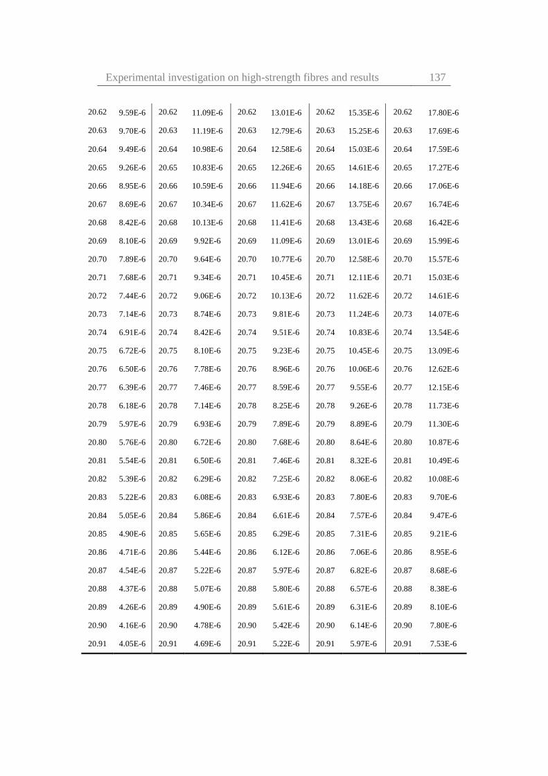
Experimental investigation on high-strength fibres and results 137
20.62 9.59E-6 20.62 11.09E-6 20.62 13.01E-6 20.62 15.35E-6 20.62 17.80E-6
20.63 9.70E-6 20.63 11.19E-6 20.63 12.79E-6 20.63 15.25E-6 20.63 17.69E-6
20.64 9.49E-6 20.64 10.98E-6 20.64 12.58E-6 20.64 15.03E-6 20.64 17.59E-6
20.65 9.26E-6 20.65 10.83E-6 20.65 12.26E-6 20.65 14.61E-6 20.65 17.27E-6
20.66 8.95E-6 20.66 10.59E-6 20.66 11.94E-6 20.66 14.18E-6 20.66 17.06E-6
20.67 8.69E-6 20.67 10.34E-6 20.67 11.62E-6 20.67 13.75E-6 20.67 16.74E-6
20.68 8.42E-6 20.68 10.13E-6 20.68 11.41E-6 20.68 13.43E-6 20.68 16.42E-6
20.69 8.10E-6 20.69 9.92E-6 20.69 11.09E-6 20.69 13.01E-6 20.69 15.99E-6
20.70 7.89E-6 20.70 9.64E-6 20.70 10.77E-6 20.70 12.58E-6 20.70 15.57E-6
20.71 7.68E-6 20.71 9.34E-6 20.71 10.45E-6 20.71 12.11E-6 20.71 15.03E-6
20.72 7.44E-6 20.72 9.06E-6 20.72 10.13E-6 20.72 11.62E-6 20.72 14.61E-6
20.73 7.14E-6 20.73 8.74E-6 20.73 9.81E-6 20.73 11.24E-6 20.73 14.07E-6
20.74 6.91E-6 20.74 8.42E-6 20.74 9.51E-6 20.74 10.83E-6 20.74 13.54E-6
20.75 6.72E-6 20.75 8.10E-6 20.75 9.23E-6 20.75 10.45E-6 20.75 13.09E-6
20.76 6.50E-6 20.76 7.78E-6 20.76 8.96E-6 20.76 10.06E-6 20.76 12.62E-6
20.77 6.39E-6 20.77 7.46E-6 20.77 8.59E-6 20.77 9.55E-6 20.77 12.15E-6
20.78 6.18E-6 20.78 7.14E-6 20.78 8.25E-6 20.78 9.26E-6 20.78 11.73E-6
20.79 5.97E-6 20.79 6.93E-6 20.79 7.89E-6 20.79 8.89E-6 20.79 11.30E-6
20.80 5.76E-6 20.80 6.72E-6 20.80 7.68E-6 20.80 8.64E-6 20.80 10.87E-6
20.81 5.54E-6 20.81 6.50E-6 20.81 7.46E-6 20.81 8.32E-6 20.81 10.49E-6
20.82 5.39E-6 20.82 6.29E-6 20.82 7.25E-6 20.82 8.06E-6 20.82 10.08E-6
20.83 5.22E-6 20.83 6.08E-6 20.83 6.93E-6 20.83 7.80E-6 20.83 9.70E-6
20.84 5.05E-6 20.84 5.86E-6 20.84 6.61E-6 20.84 7.57E-6 20.84 9.47E-6
20.85 4.90E-6 20.85 5.65E-6 20.85 6.29E-6 20.85 7.31E-6 20.85 9.21E-6
20.86 4.71E-6 20.86 5.44E-6 20.86 6.12E-6 20.86 7.06E-6 20.86 8.95E-6
20.87 4.54E-6 20.87 5.22E-6 20.87 5.97E-6 20.87 6.82E-6 20.87 8.68E-6
20.88 4.37E-6 20.88 5.07E-6 20.88 5.80E-6 20.88 6.57E-6 20.88 8.38E-6
20.89 4.26E-6 20.89 4.90E-6 20.89 5.61E-6 20.89 6.31E-6 20.89 8.10E-6
20.90 4.16E-6 20.90 4.78E-6 20.90 5.42E-6 20.90 6.14E-6 20.90 7.80E-6
20.91 4.05E-6 20.91 4.69E-6 20.91 5.22E-6 20.91 5.97E-6 20.91 7.53E-6
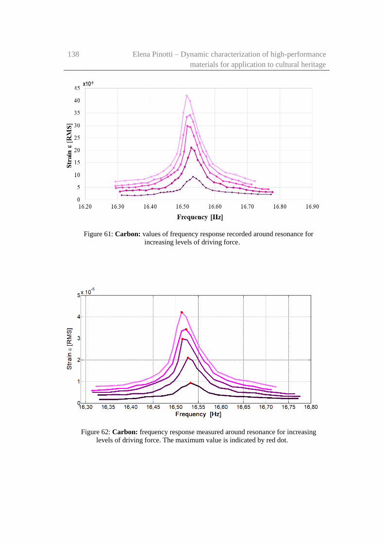
138 Elena Pinotti – Dynamic characterization of high-performance
materials for application to cultural heritage
Figure 61: Carbon: values of frequency response recorded around resonance for
increasing levels of driving force.
Figure 62: Carbon: frequency response measured around resonance for increasing
levels of driving force. The maximum value is indicated by red dot.

Experimental investigation on high-strength fibres and results 139
Table 11: Carbon: strain values calculated from the numerical data acquired during the
forced tests.
1.0 [V] 3.0 [V] 5.0 [V] 7.0 [V] 9.0 [V]
Freq. ε Freq. ε Freq. ε Freq. ε Freq. ε
[Hz] [RMS] [Hz] [RMS] [Hz] [RMS] [Hz] [RMS] [Hz] [RMS]
16.31 1.821E-6 16.31 3.343E-6 16.30 4.776E-6 16.29 5.612E-6 16.29 7.313E-6
16.33 1.731E-6 16.33 3.761E-6 16.32 4.955E-6 16.31 5.821E-6 16.32 7.731E-6
16.35 1.701E-6 16.35 3.791E-6 16.34 4.985E-6 16.33 6.090E-6 16.36 8.119E-6
16.37 1.761E-6 16.37 4.030E-6 16.36 5.045E-6 16.35 6.358E-6 16.38 8.358E-6
16.39 2.060E-6 16.39 3.791E-6 16.38 5.612E-6 16.37 6.776E-6 16.40 9.343E-6
16.41 2.209E-6 16.41 4.478E-6 16.40 5.821E-6 16.39 6.836E-6 16.42 10.179E-6
16.43 2.925E-6 16.43 4.388E-6 16.42 6.507E-6 16.41 8.239E-6 16.44 11.701E-6
16.44 2.955E-6 16.45 4.955E-6 16.44 7.881E-6 16.43 8.657E-6 16.46 14.000E-6
16.45 3.164E-6 16.47 6.627E-6 16.46 9.254E-6 16.45 10.119E-6 16.48 18.567E-6
16.46 3.224E-6 16.48 7.970E-6 16.47 10.149E-6 16.47 12.925E-6 16.49 25.045E-6
16.47 3.403E-6 16.49 8.776E-6 16.48 11.104E-6 16.49 18.328E-6 16.50 35.164E-6
16.48 3.791E-6 16.50 10.478e-6 16.49 12.060E-6 16.50 26.119E-6 16.51 42.119E-6
16.49 4.149E-6 16.51 13.254E-6 16.50 14.269E-6 16.51 33.493E-6 16.52 39.970E-6
16.50 5.642E-6 16.52 16.925E-6 16.51 19.403E-6 16.52 34.239E-6 16.53 34.806E-6
16.51 7.313E-6 16.53 21.045E-6 16.52 29.791E-6 16.53 31.582E-6 16.55 25.731E-6
16.52 8.030E-6 16.54 19.791E-6 16.53 29.284E-6 16.54 27.075E-6 16.57 19.672E-6
16.53 9.343E-6 16.55 16.090E-6 16.54 25.791E-6 16.55 22.955E-6 16.59 14.507E-6
16.54 8507E-6 16.56 14.060E-6 16.55 22.090E-6 16.56 19.433E-6 16.63 11.015E-6
16.55 7.552E-6 16.58 9.164E-6 16.56 18.328E-6 16.57 17.582E-6 16.66 10.179E-6
16.56 6.030E-6 16.60 7.045E-6 16.57 15.075E-6 16.58 14.030E-6 16.69 8.716E-6
16.57 4.836E-6 16.62 6.507E-6 16.59 10.925E-6 16.61 10.657E-6 16.72 7.522E-6
From the experimental results previously reported in Figures 57-62, a weak
nonlinear behaviour of the response was evident. Increasing the input voltage, the
peak of the curves indicates that the resonance frequency tends to shift towards
lower values of frequency.

140 Elena Pinotti – Dynamic characterization of high-performance
materials for application to cultural heritage
Survey on nonlinear system identification in structural dynamics
System identification is a method of estimating the mathematical model of a
system from input and output measurements. System identification methodologies
can employed to a broad range of applications like industrial processes, control
systems, economic data, biology and the life sciences, medicine, social systems
and many more.
The most common approaches in system identification assume a linear
relationship between input and output. Modal identification is the most common
and widely applied approach in structural engineering field. It entails in estimating
the modal parameters of the investigated structure on the bases of vibration data
collected.
Most systems encountered in the real world are nonlinear to some extent, and
in many practical applications nonlinear models are required to achieve an
acceptable prediction accuracy.
One of the most recent and comprehensive classification and review on non-
linear identification methodologies is proposed by Kerschen (Noël & Kerschen,
2017)(Kerschen, et al., 2006) . He suggests to consider the identification of
nonlinear structural models as a three-step process:
detection
characterization
parameter estimation
The focus of his literature review is on the classification of parameter
estimation methods. They may fall into seven categories:
linearization methods
time-domain methods
frequency-domain methods
time-frequency domain methods
modal methods
black-box modelling
numerical modal updating
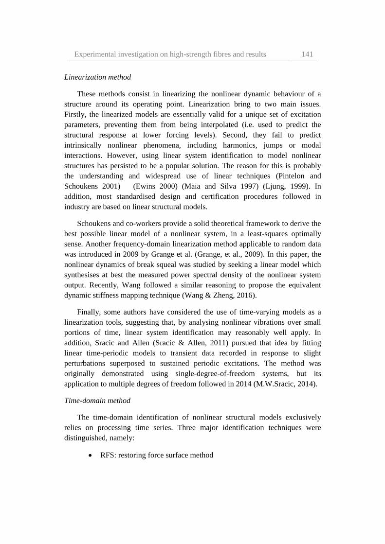
Experimental investigation on high-strength fibres and results 141
Linearization method
These methods consist in linearizing the nonlinear dynamic behaviour of a
structure around its operating point. Linearization bring to two main issues.
Firstly, the linearized models are essentially valid for a unique set of excitation
parameters, preventing them from being interpolated (i.e. used to predict the
structural response at lower forcing levels). Second, they fail to predict
intrinsically nonlinear phenomena, including harmonics, jumps or modal
interactions. However, using linear system identification to model nonlinear
structures has persisted to be a popular solution. The reason for this is probably
the understanding and widespread use of linear techniques (Pintelon and
Schoukens 2001) (Ewins 2000) (Maia and Silva 1997) (Ljung, 1999). In
addition, most standardised design and certification procedures followed in
industry are based on linear structural models.
Schoukens and co-workers provide a solid theoretical framework to derive the
best possible linear model of a nonlinear system, in a least-squares optimally
sense. Another frequency-domain linearization method applicable to random data
was introduced in 2009 by Grange et al. (Grange, et al., 2009). In this paper, the
nonlinear dynamics of break squeal was studied by seeking a linear model which
synthesises at best the measured power spectral density of the nonlinear system
output. Recently, Wang followed a similar reasoning to propose the equivalent
dynamic stiffness mapping technique (Wang & Zheng, 2016).
Finally, some authors have considered the use of time-varying models as a
linearization tools, suggesting that, by analysing nonlinear vibrations over small
portions of time, linear system identification may reasonably well apply. In
addition, Sracic and Allen (Sracic & Allen, 2011) pursued that idea by fitting
linear time-periodic models to transient data recorded in response to slight
perturbations superposed to sustained periodic excitations. The method was
originally demonstrated using single-degree-of-freedom systems, but its
application to multiple degrees of freedom followed in 2014 (M.W.Sracic, 2014).
Time-domain method
The time-domain identification of nonlinear structural models exclusively
relies on processing time series. Three major identification techniques were
distinguished, namely:
RFS: restoring force surface method

142 Elena Pinotti – Dynamic characterization of high-performance
materials for application to cultural heritage
NARMAX: nonlinear autoregressive moving average with exogenous
inputs modelling
TNSI: time-domain nonlinear subspace identification method
In a NARMAX technique, the system is modelled in terms of a nonlinear
functional expansion of lagged input, output and prediction errors. The functional
description of an actual system can be very complex and the explicit form of this
functional is usually unknown. Therefore, the practical modelling of real signal
must be based upon a chosen set of the unknown functions. The input–output
model is a means of describing the dynamics of a system. Furthermore, an
important question regarding the model is how to relate this information in some
straightforward way that will provide an adequate approximation to a wide class
of the systems with a reasonable computational cost. In general terms, it is
admitted that apply the NARMAX framework to large-scale structures is a
difficult to endeavour, as it suffers from a rapid explosion in the number of
parameters, even in the case of systems with reasonable dimension (Chen, et al.,
2007) (Peng, et al., 2011).
The RFS method constitutes one of the earliest identification methodologies
(Masri & Caughey, 2010). It has continued to attract attention during the past
decade. Parameter estimation based on the RFS method is commonly restricted to
systems with a few degrees of freedom. It consists in the direct fitting of
Newton’s second law. However, the method can still be exploited to visualise
qualitatively nonlinear restoring forces in complex structures.
Applications of the RFS method to identification of nonlinear stiffness
mechanisms have been numerous. In a work of Saad et al. (Saad, et al. 2006), the
prediction capabilities of a nonlinear restoring force model of two elastomer
specimens were compared to rheological equations based on traction-compression
and shear test data. Complex damping nonlinearities have equally been addressed
in the technical literature (Worden, et al. 2009) (Ceravolo, Erlicher and Zanotti
Fragonara 2013) (Xu, He and Dyke 2015).
Nonlinear subspace methods, originally proposed in the control literature
(Lacy and Bernstein 2005), were first applied to mechanical systems by
Marchisiello & Garibaldi in 2008 (Marchesiello and Garibaldi 2008). The time-
domain nonlinear subspace identification (TNSI) method represents a major
advance across the field. TNSI is a nonlinear generalisation of the classical time-
domain linear subspace identification algorithms (VanOverschee and DeMoor

Experimental investigation on high-strength fibres and results 143
1996). The implementation of this method builds on robust numerical tools, such
as the QR and singular value decompositions, yielding superior accuracy
compared to competing approaches like the NIFO (Adams & Allemang, 1999)
and the conditioned reverse path (CRP) technique (Richards and Singh 1998),
which will be introduced in in the subsection dedicated to frequency-domain
methods.
Frequency-domain methods
The frequency domain methods use to process a wider type of data than in the
time-domain. They can take the form of Fourier spectra, frequency response and
transmissibility functions, or power spectra densities.
Three methods were surveyed as promising frequency-domain approaches:
NIFO, the nonlinear identification through feedback of the outputs
(Richards & Singh, 1998)
CRP, the conditioned reverse path methods (Richards & Singh, 1998)
Volterra series (Schetzen 1980).
NIFO method is based on a compact formulation referred to as nonlinear
identification through feedback of the outputs. The data associated with the spatial
configuration of the nonlinearities provide additional information that is needed to
simultaneously identify the linear and nonlinear parts of the system. Adams and
Allemang (Adams & Allemang, 1999) introduced the frequency domain nonlinear
identification in the form of a method that decouples the linear and nonlinear
dynamics of a system and estimates the linear and nonlinear components in one
computational step.
CRP method is based on the construction of a hierarch of uncorrelated
response components in the frequency domain. If excitations are applied at
each response location, parameter estimation is completed by solving an
algebraic system for each frequency, by using the reverse path method.
However, when the number of excitations is smaller than the number of
response locations and non-linearities are far from the locations of the
excitations, the reverse path method cannot be directly applied (Garibaldi
2003).
Another traditional way of addressing system identification in the frequency
domain is the use of functional series, and in particular of the Volterra series

144 Elena Pinotti – Dynamic characterization of high-performance
materials for application to cultural heritage
(Schetzen, 1980). In short the output can be considered a nonlinear convolution
of the input where nonlinear behaviours are captured by high order kernels
(Friston, et al., 2000). The common limit of Volterra identification of high-
dimensional systems is the very high number of parameters to be estimated.
Volterra series have also constituted the basis of the new concept of nonlinear
output frequency response functions developed during the last 10 years or so by
Billings and co-workers (Lang & Billings, 2005) (Peng, et al., 2007). This method
found application in linear (Peng, et al., 2007) and nonlinear (Peng, et al., 2008)
system identification.
Time-frequency methods
Because nonlinear oscillations are intrinsically frequency-energy dependent,
time–frequency transformations generally offer useful insight into the dynamics
of nonlinear systems. Well-established methods, such as the wavelet and Hilbert
transforms, have continued to be used during the last 10 years as nonlinear system
identification tools, and, particularly, in the identification of backbone curves,
(Heller, et al., 2009) (Demarie, et al., 2010). In addition, two new techniques for
the decomposition of multicomponent signals emerged during this period:
EMD, the empirical mode decomposition (Norden Huang, et al., 1998)
HVD, Hilbert vibration decomposition (Feldman, 2006) (Feldman,
2007).
TFIE, time-frequency instantaneous estimator (Spina, et al., 1996)
(Ceravolo, et al., 2013).
The idea of EMD is to decompose the original signal into a sum of elemental
components, the intrinsic mode functions (IMFs). The extraction process, termed
sifting process, relies on a spline approximation of the lower and upper envelopes
of the signal based on its extrema (Kerschen, et al., 2008).
HVD method is a distinct approach to the decomposition of a vibration signal
into a series of mono-component signals. HVD is based on the assumptions that
the original signal is formed of a superposition of quasi-harmonic functions, and
that the envelopes of each vibration component differ.
The HVD method was applied for the identification of nonlinear systems with
two degrees of freedom (Feldman, 2007), but has not yet been applied to larger-
scale structures. It found different applications in structural dynamics

Experimental investigation on high-strength fibres and results 145
(Gendelman, et al., 2008) and the analysis of linear (Bertha & Golinval, 2014) and
nonlinear (Feldman, 2014) time-varying systems.
The EMD and HVD methods have limitations and have to be used with great
attention (Braun & Feldman, 2011) (Huang, et al., 2012). Despite everything, they
represent important additions to the nonlinear structural dynamist’s toolbox.
TFIE is a method recently proposed able to cope with non-linear and hysteretic
systems where the parameter identification can be carried out minimising a
residual signal in the time-frequency domain using any time-frequency transform.
This allows to the estimation of instantaneous optimal estimator of the model.
Modal methods
Modal features (natural frequencies, damping ratios and mode shapes), form
the basis of classical linear design strategies in engineering dynamics. They
provide an effective and intuitive way to study the structural behaviour around
resonances, which is one of the main limiting factors as for integrity and
certification (Ewins, 2006). On the contrary, nonlinear modal identification is a
quite recent research field, as confirmed by the very few related methods surveyed
in 2006 (Kerschen, et al., 2006). Nowadays it is a very active area of investigation
that has showed important progress during the last decade. These progresses have
been accompanied by the emergence of efficient algorithms, to carry out
theoretical nonlinear modal analysis (Renson, et al., 2016).
The popularity of modal analysis stems from its great generality. Modal
parameters can describe the behaviour of a system for any input type and any
range of the input.
A couple of example of nonlinear modal method are
CONCERTO method
NLRDM method
The COde for Nonlinear identifiCation from mEasured Response To
vibratiOn (CONCERTO), proposed by Carrella et al. (Carrella & Ewins, 2011)
identifies an isolated nonlinear resonance based on stepped-sine data. Since
CONCERTO relies on a single-harmonic assumption, it adopts a linearized view
of nonlinear modal identification, and yields equivalent natural frequencies and
damping ratios which vary with the amplitude of motion.

146 Elena Pinotti – Dynamic characterization of high-performance
materials for application to cultural heritage
Unlike CONCERTO, the nonlinear resonant decay method (NLRDM) can
perform multiple-mode identification by introducing nonlinear coupling terms in
an otherwise linear modal-space model of the tested structure. This method was
recognised as one of the most promising nonlinear modal identification
approaches in the early 2000s (Kerschen, et al., 2006). If no further developments
of the theoretical foundations of NLRDM were brought during the last 10 years,
the method was successfully validated using structures of increasing complexity,
namely a two-degree-of-freedom system with free play (Yang, et al., 2006), a
single- bay panel structure (Platten, et al., 2009), a wing with two stores
connected by means of nonlinear pylons (Platten, et al., 2009), a geometrically
nonlinear joined-wing structure, and a complete transport aircraft (Fuellekrug &
Goege, 2012).
Black-box method
The aforementioned nonlinear system identification methodologies are
essentially based on the selection of a model structure based on available prior
knowledge, and processing data to estimate its parameters. Accessing prior
knowledge, can however be very difficult in many cases owing to the highly
individualistic nature of real nonlinearities. This makes very difficult the
specification of an accurate, physically‐motivated model in terms of macroscopic
nonlinear stiffness and damping lumped elements. The nonlinear black-box
situation is much more difficult. The main reason is that nothing is excluded, and
a very rich spectrum of possible model descriptions must be handled.
Recently, a new black-box model structure based on a state-space
representation of measured data was proposed (Paduart, et al., 2010). It builds on
nonlinear model terms constructed as a multivariate polynomial combination of
the state and input variables. This approach proved successful in the identification
of very diverse nonlinear systems, including a magnetorheological damper
(Paduart, et al., 2010), a wet-clutch device (Widanage, et al., 2011), and a Li-Ion
battery (Relan, et al., 2015). However, as usual in black-box identification, it
suffers from a combinatorial increase in the number of parameters because of the
multivariate nature of the representation.
Model updating method
Techniques to detect damage in civil structures using vibrational data have
been under development for about two decades, and are currently a topic of
widespread interest in the international community (Wu & Abe, 2003).

Experimental investigation on high-strength fibres and results 147
Numerical models have to be compared with experimental data and subsequently
updated to improve their reliability.
Nonlinear modal updating method should be used for different applications.
Evaluating degradation in the capacity of a structure requires construction of an
updated nonlinear finite element (FE) model. In each structures, it is necessary to
distinguish between the various types of damage to have a true understanding of
the condition of the structure, and this may only be possible through proper
updating of a nonlinear FE model. Each model updating technique has its
assumptions and applicable range. Over the lifetime of a structure, it is possible
that these assumptions may not hold at all times. It is possible to apply a linear o
nonlinear model updating as required.
Figure 63: flowchart of the general numerical procedure. Source (Song, et al., 2013).
As shown in Figure 63, the entire procedure consists of three stages. In the
first stage (i.e., nonlinear FE modelling and analysis), both reference and
analytical models were built using the same material parameters (no damage), and
then the damage was imposed to the reference model by enforcing a damaging
loading condition. Then, the modal information of both models was fed into the
objective function block, which was the beginning of the second stage. In the
second stage (i.e., FE model updating), the discrepancies between the damaged
reference model and the analytical model were compared in the scores of the
objective function values. The analytical model was updated using a chosen

148 Elena Pinotti – Dynamic characterization of high-performance
materials for application to cultural heritage
optimization program with iterative evaluations of the objective function value.
The final stage (i.e., nonlinear FE analysis restart) was designed to check the
efficacy of the updated model. By applying a new damaging input (a load case
resulting in damage of the structure) to both the damaged reference model and the
updated analytical model, the obtained responses were compared (Song, et al.,
2013).
Dynamic parameter estimation
Given the simplicity of the case and the materials under investigation, the
non-linearity was considered enclosed in a cubic nonlinear coefficient. This
solution seems to well apply to the described case.
To try to quantify this non-linearity, the following expression, which take into
account it, was applied. The following expression defines the dynamics of a
system excited by a harmonic force and characterized by a cubic non-linearity
(Kalmar-Nagy & Balachandran, 2011):
�̈� + 2𝜀𝜁�̇� + 𝜔𝑛2𝑢 + 𝜀𝜒𝑢3 = 𝐹 cos(Ω𝑡) (18)
where 𝜁 is the damping, 𝜒 represents the coefficient of cubic non-linearity, 𝜔𝑛
is the natural angular frequency of the linear system, and Ω is the excitation
frequency.
Equation (18) describes, the motion of a damped nonlinear oscillator having a
more complicated behaviour compared to the simple harmonic motion. In
physical terms, the equation (18) models a mass-spring system, whose spring
stiffness does not exactly follow the Hooke's law. Our interest is on the cubic
stiffness coefficient 𝜒 (cubic non-linearity index), which controls the nonlinear
part of the restoring force.
Respect to the linear behaviour, the amplitude of the response into the
nonlinear one can varying depending on the material investigated. If χ is negative,
the material shows a softening behaviour, if is equal to zero represents a linear
behaviour, and finally if is positive the material shows a hardening behaviour. In
the following Figure 64 are shown an explanation of the response curves to
varying the cubic stiffness coefficient γ, which was called χ in this dissertation.

Experimental investigation on high-strength fibres and results 149
Figure 64: amplitude-response curves for a varying strength of nonlinearities γ.
Source (Kalmar-Nagy & Balachandran, 2011).
5.1.3 Nonlinear identification of the backbone curve
In order to define the dynamics of a system characterized by cubic non-
linearity excited by a harmonic force, the following expression found in the open
literature, which represents the Duffing oscillator equation was exploited:
𝑚�̈� + 𝑐�̇� + 𝑘𝑥 + 𝜒𝑥3 = 𝐹 (19)
where F is the external sinusoidal forcing term, m the mass of the system, c
the linear viscous damping term, and χ the cubic stiffness coefficient, respectively.
In order to identify the nonlinear material behaviour, the Krylov-Bogoliubov
method was used to determine the variation of the first nonlinear resonance
frequency of a Duffing oscillator of equation 19. It was characterized by a
nonlinear force-displacement relationship (Kalmar-Nagy & Balachandran, 2011)
(Nayfeh & Mook, 1995).
The distortion in frequency f was quantified as:
𝑓 = 𝑓𝑛 [1 +3
8
𝜒
𝑘𝑎2] (20)

150 Elena Pinotti – Dynamic characterization of high-performance
materials for application to cultural heritage
where a is the amplitude of the response, 𝑘 is the linear stiffness, 𝑓𝑛 is the
natural frequency and 𝜒 is the cubic stiffness coefficient.
Equation 20 was used to identify the so-called backbone curve of the
nonlinear response, as a red line in Figures 65-67 highlights it. The red dots
indicate the maximum amplitude values, corresponding to the resonance
frequency at different amplitudes of the external excitating force. The amplitude
response of a nonlinear system is generally multivalued, as opposed to a linear
system. The results presented below show a softening behavior (negative value of
cubic stiffness parameter, because the response curve deviates toward lower
frequencies).
This approach confirmed the high sensitivity of this new prototype-testing
machine for the dynamic characterization of high-strength materials, with regard
to low levels of non-linearity. Indeed, the nonlinear effects in the measurements
were provided only by very small intrinsic nonlinear levels in the materials.
Figure 65: Silicon Carbide: frequency response measured around resonance for
increasing levels of driving force. The red dots highlight the maximum of the response
curve and the dashed red line is the estimated backbone response curve.

Experimental investigation on high-strength fibres and results 151
Figure 66: Kevlar® 29: frequency response measured around resonance for increasing
levels of driving force. The red dots highlight the maximum of the response curve and the
dashed red line is the estimated backbone response curve.
Figure 67: Carbon: frequency response measured around resonance for increasing levels
of driving force. The red dots highlight the maximum of the response curve and the
dashed red line is the estimated backbone response curve.

152 Elena Pinotti – Dynamic characterization of high-performance
materials for application to cultural heritage
The cubic stiffness coefficient obtained in these cases are equal to 𝜒 =
−2.21 ∙ 1012 𝑁 𝑚3⁄ for silicon carbide sample, −4.03 ∙ 1011 𝑁 𝑚3⁄ for Kevlar®
29 sample in pristine condition, and −2.08 ∙ 1010 𝑁 𝑚3⁄ for carbon sample.
5.1.4 Dissipation properties and quality factor: experimental
evaluation
In physics and engineering the quality factor (Q) is a dimensionless parameter
that describes how under-damped an oscillator or resonator is, and characterizes a
resonator's bandwidth relative to its centre frequency. Higher Q indicates a lower
rate of energy loss relative to the stored energy of the resonator. Resonators with
high quality factors have low damping so that they ring or vibrate longer.
In the context of resonators, there are two common definitions for Q, which
are not necessarily equivalent. They become approximately equivalent as Q
becomes larger, meaning the resonator becomes less damped. One of these
definitions is the frequency-to-bandwidth ratio of the resonator:
𝑄 =𝑓𝑟
Δ𝑓=
𝜔𝑟
Δ𝜔 (21)
where 𝑓𝑟 is the resonant frequency, ∆𝑓 is the resonance width or full width at
half maximum (the bandwidth over which the power of vibration is greater than
half the power at the resonant frequency), 𝜔𝑟 = 2𝜋𝑓𝑟 is the angular resonant
frequency, and finally Δ𝜔 is the angular half-power bandwidth.
The other common definition for the quality factor is the ratio of the energy
stored in the oscillating resonator to the energy dissipated per cycle by damping
processes:
𝑄 = 2𝜋𝐸𝑛𝑒𝑟𝑔𝑦 𝑠𝑡𝑜𝑟𝑒𝑑
𝐸𝑛𝑒𝑟𝑔𝑦 𝑑𝑖𝑠𝑠𝑖𝑝𝑎𝑡𝑒𝑑 𝑝𝑒𝑟 𝑐𝑦𝑐𝑙𝑒= 2𝜋𝑓𝑟
𝐸𝑛𝑒𝑟𝑔𝑦 𝑠𝑡𝑜𝑟𝑒𝑑
𝑃𝑜𝑤𝑒𝑟 𝑙𝑜𝑠𝑠 (22)
where in electrical systems, the stored energy is the sum of energies stored in
lossless inductors and capacitors, while the lost energy is the sum of the energies
dissipated in resistors per cycle. In mechanical systems, the stored energy is the
maximum possible stored energy, or the total energy (the sum of the potential and
kinetic energies at some point in time, for example). The lost energy is the work
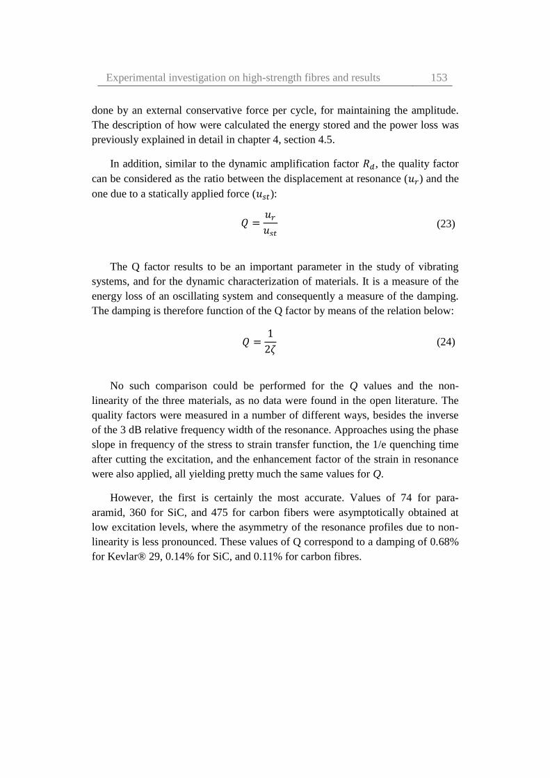
Experimental investigation on high-strength fibres and results 153
done by an external conservative force per cycle, for maintaining the amplitude.
The description of how were calculated the energy stored and the power loss was
previously explained in detail in chapter 4, section 4.5.
In addition, similar to the dynamic amplification factor 𝑅𝑑, the quality factor
can be considered as the ratio between the displacement at resonance (𝑢𝑟) and the
one due to a statically applied force (𝑢𝑠𝑡):
𝑄 =𝑢𝑟
𝑢𝑠𝑡 (23)
The Q factor results to be an important parameter in the study of vibrating
systems, and for the dynamic characterization of materials. It is a measure of the
energy loss of an oscillating system and consequently a measure of the damping.
The damping is therefore function of the Q factor by means of the relation below:
𝑄 =1
2𝜁 (24)
No such comparison could be performed for the Q values and the non-
linearity of the three materials, as no data were found in the open literature. The
quality factors were measured in a number of different ways, besides the inverse
of the 3 dB relative frequency width of the resonance. Approaches using the phase
slope in frequency of the stress to strain transfer function, the 1/e quenching time
after cutting the excitation, and the enhancement factor of the strain in resonance
were also applied, all yielding pretty much the same values for Q.
However, the first is certainly the most accurate. Values of 74 for para-
aramid, 360 for SiC, and 475 for carbon fibers were asymptotically obtained at
low excitation levels, where the asymmetry of the resonance profiles due to non-
linearity is less pronounced. These values of Q correspond to a damping of 0.68%
for Kevlar® 29, 0.14% for SiC, and 0.11% for carbon fibres.
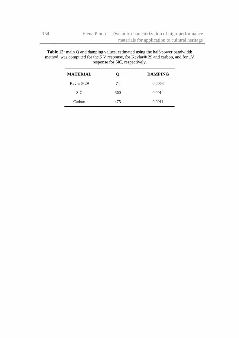
154 Elena Pinotti – Dynamic characterization of high-performance
materials for application to cultural heritage
Table 12: main Q and damping values, estimated using the half-power bandwidth
method, was computed for the 5 V response, for Kevlar® 29 and carbon, and for 1V
response for SiC, respectively.
MATERIAL Q DAMPING
Kevlar® 29 74 0.0068
SiC 360 0.0014
Carbon 475 0.0011

Experimental investigation on high-strength fibres and results 155
156 Elena Pinotti – Dynamic characterization of high-performance
materials for application to cultural heritage
Chapter 6
Experimental investigation and
results on damaged Kevlar® 29
samples
In Chapter 5 the experimental investigation and the results performed on three
different high-strength materials were presented. The experimental investigation
consisted into the dynamic characterization of high-strength fibres, by means of
simple non-destructive non-linearity tests. Subsequently, three para-aramid
samples of Kevlar® 29 were subjected to UV rays to different time, and tested.
In this chapter the results of this second experimental campaign were
presented. The demonstrated sensitivity to UV rays of these kind of high-strength
materials, in terms of decreased stiffness and potential relaxation, may be a
discriminating factor when choosing the type of material to be employed for the
confinement interventions on concrete or masonry columns, or vaults in historic
buildings.
The idea has been to use the demonstrated existence of weak nonlinearities
(through a non-linearity index) (Chapter 5), which may be detected in the forced
dynamic response of the specimen, as indicators for safety and lifecycle
assessment of high-performance fibres. The results could be applied, as a possible
alternative, in Structural Health Monitoring (SHM) or damage detection

Experimental investigation and results on damaged Kevlar® 29
samples
157
application. Particularly interesting is the application to monitoring existing high-
strength materials reinforcements. These reinforcements are applied to buildings
of particular historical and artistic interest, which more than others are in need of
monitoring and protection.
Part of the work described in this Chapter has also been published in
Composite Structures (Ceravolo, et al., 2018)
6.1 Effects of UV exposure on high-strength materials:
background
High-strength materials are currently employed as a reinforcing material for
buildings. In this situation, they are permanently subjected to external factors
(environmental factors), which had the ability to degrade these materials
depending on the exposure to different elements, and the exposure time to these
elements over the life of the system. The material should be chosen, and designed
based on these considerations, in order to maximise the benefits of this
reinforcement technique (Granata & Parvin, 2001). In the specific area of
structural engineering and retrofitting, problems arising from the structural
performance of polymeric materials after long-term exposure to the agents render
the end-users still cautious when and where to apply them (Oliveira & Creus,
2004).
Systems using high-strength materials can be suitable for every need taken
advantage of the possibility to have different FRP configurations, material
properties, and installations. To ensure that high-strength materials will be used
effectively and widely in a common practice, the engineers should evaluate all
aspects of the project, including the structures location. In particular, when high-
strength materials used in reinforcement technique, were externally bonded to
structures they are exposed to ultraviolet (UV) rays, and consequently to UV
degradation. UV rays have the ability to degrade the resin matrix, in which the
fibres were embedded, and can even degrade the fibres themselves after sufficient
exposure.
The UV rays are one part in the solar spectrum, and their wavelengths
contained in the sunlight are measured from 200 nm to 400 nm. UV rays are
dangerous for any polymer, on which the corrosion process caused by the oxygen
in the atom state would be accelerated because of the presence of the UV ray,
resulting in a weight loss and deterioration (HuangGu, 2005).

158 Elena Pinotti – Dynamic characterization of high-performance
materials for application to cultural heritage
In other works, available into open literature (Silva, 2007) (Silva & Biscaia,
2008) (Wang, et al., 2012) (Cai, et al., 2014) (Micelli & Nanni, 2004), the strength
of the filaments before and after the UV exposure was tested, in order to evaluate
the strength decrement function of the time exposition.
The author in a work (HuangGu, 2005) asserts that short time exposure to the
UV ray does not damage the Kevlar® fibres. However, prolonged exposure to the
UV ray will cause strength decrease. The main bonds into the Kevlar® fibre are
C–O and N–H, and the corresponding wavelengths of their bond energy are 340
and 306 nm, respectively. Consequently, the required wavelength to break the N–
H bond is 306 nm. After the UV exposure, micro cracks on the fibre surface
appear. Aging studies on Kevlar® were also conducted by Arrieta et al. (Arrieta,
et al., 2011).
Another work (Said, et al., 2006) reports the changes into mechanical
behaviour in the cases of pre and post-exposure to UV rays of four commercial
high-strength fibres (Zylon® HM, Vectran® T-97, Kevlar® 49, Spectra® 1000).
The experimental campaign was conducted by using a weatherometer with a
Xenon lamp, emitting UV rays at 340 nm at an irradiance of 1.1 W/m2 (Figure
68). The results indicate that exposing high-strength fibres in continuous yarn
form to UV could cause serious loss strength of the fibres, with the exception of
Spectra® fibres.
Figure 68: weatherometer with a Xenon lamp, emitting UV rays at 340 nm at an
irradiance of 1.1 W/m2 used in an experimental tests. Source (Said, et al., 2006).

Experimental investigation and results on damaged Kevlar® 29
samples
159
Previous studies have reported results on UV degradation of thick ropes. The
objective of this research was to study high-strength fibres in single continuous
yarn form, and to quantify their strength loss with UV exposure. This work further
explains that Kevlar® is self-screening. Its light stability depends on the thickness
of the exposed item. Very thin Kevlar® 49 fabric, if directly exposed to very high
intensity sunlight for an extended period, will lose about half its tensile strength
within few days. In thicker element, such as a half-inch diameter rope, the outer
layer protects the majority of the rope and strength loss is minimised (Said, et al.,
2006).
The aim of the work presented in this Chapter is to identify, assess and
quantify the changes in the fibre material response when exposed to UV light on
the basis of several parameters taken into consideration such as the resonant
frequency of the spring-mass system, the Q-factor, and a non-linearity index.
These results could be used as damage indicators for safety and lifecycle
assessment of high-strength materials.
6.2 Experimental investigation on damaged Kevlar® 29
samples
After that the tests on undamaged para-aramid sample of Kevlar® 29 were
carried out (Chapter 5), it was decided to damage it. The effect that the damage
could have on the behaviour of the fibres will then be evaluated by repeating the
forced tests and comparing the results obtained with those already reported for the
undamaged sample.
The type of procedure chosen to cause the damage is a prolonged exposure to
UV rays. UV rays attack many of the natural and synthetic polymers. This
problem is known as UV degradation, and is more common in products constantly
exposed to sunlight. In particular, a continuous and prolonged exposure results to
be more harmful than an intermittent one, because the dangerousness of the attack
depends on the extent and the degree of exposure. The polymers that possess UV-
absorption groups, such as aromatic rings (aramid and para-aramid), can be
sensitive to the effect of ultraviolet radiation, and often should be protected from
the deleterious effects that could have the sunlight. The damage caused by UV
effects on this type of materials, which are visible after a long time exposure, can
be evaluated by means of accelerated exposure testing.
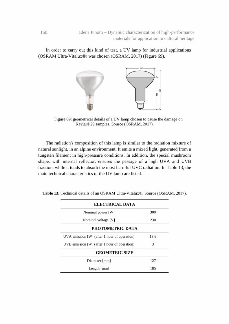
160 Elena Pinotti – Dynamic characterization of high-performance
materials for application to cultural heritage
In order to carry out this kind of test, a UV lamp for industrial applications
(OSRAM Ultra-Vitalux®) was chosen (OSRAM, 2017) (Figure 69).
Figure 69: geometrical details of a UV lamp chosen to cause the damage on
Kevlar®29 samples. Source (OSRAM, 2017).
The radiation's composition of this lamp is similar to the radiation mixture of
natural sunlight, in an alpine environment. It emits a mixed light, generated from a
tungsten filament in high-pressure conditions. In addition, the special mushroom
shape, with internal reflector, ensures the passage of a high UVA and UVB
fraction, while it tends to absorb the most harmful UVC radiation. In Table 13, the
main technical characteristics of the UV lamp are listed.
Table 13: Technical details of an OSRAM Ultra-Vitalux®. Source (OSRAM, 2017).
ELECTRICAL DATA
Nominal power [W] 300
Nominal voltage [V] 230
PHOTOMETRIC DATA
UVA emission [W] (after 1 hour of operation) 13.6
UVB emission [W] (after 1 hour of operation) 3
GEOMETRIC SIZE
Diameter [mm] 127
Length [mm] 185

Experimental investigation and results on damaged Kevlar® 29
samples
161
Figure 70, shows also the relative spectral power distribution provided by the
datasheet.
Figure 70: power spectra distribution of Ultra-Vitalux® lightbulb subdivided for the
different components of the electromagnetic spectrum. Source (OSRAM, 2017).
It can be noted that the ultraviolet radiation is the portion of the
electromagnetic spectrum, in which the wavelength ranges from 100 to 400 nm. It
corresponds to the part immediately lower than the human eye visible light, and
just over to X-rays.
The UV radiation is further divided into three different wavelength bands:
UVA, wavelength ranges from 315 to 400 nm
UVB, wavelength ranges from 280 to 315 nm
UVC, wavelength ranges from 100 to 280 nm
The graph in Figure 70 clearly shows as the greater peaks are in
correspondence of the spectrum's portion that identifies the UVA radiation, or
however for wavelengths not particularly high.

162 Elena Pinotti – Dynamic characterization of high-performance
materials for application to cultural heritage
If compared to the solar spectrum, the emission spectrum of the UV lamps is
constituted by discrete lines, which taking a greater entity for some critical values
of wavelength. The material exhibits a high absorption of radiation in these
points. This fact explains the particular effectiveness of this kind of lamps in the
various industrial processes in which it is used.
The peaks related to the UV lamp's spectrum that exceed the trend of the solar
spectrum, are those relating to UVA and UVB fractions. These radiations are
those most harmful for the material under investigation in this work.
Consequently, is easy to see the effectiveness of the chosen lamp in order to
damage the samples under investigation. Since most of the UVA emission is in
that bright line, its power content can be taken to be roughly equal to the UVA
total flux specification of 13.6 W given in Table 13, which is then used here to
figure out the total radiation dose per hour of exposure.
At this point, the chosen lamp for damaging the sample was mounted on a
support, specially realised with recycled materials. The experiment was conducted
into the Metrology Laboratory of the Department of Electronics of the Politecnico
di Torino (Figure 71).
A sheet metal cylinder (∅13 cm) was used to focus the most part of the light
toward the fibre sample. It is necessary to ensure the presence of an open space
below the cylinder to ensure a natural air recirculation during the test.
Figure 71: the experimental setup used to focus the light flux onto fibre samples.
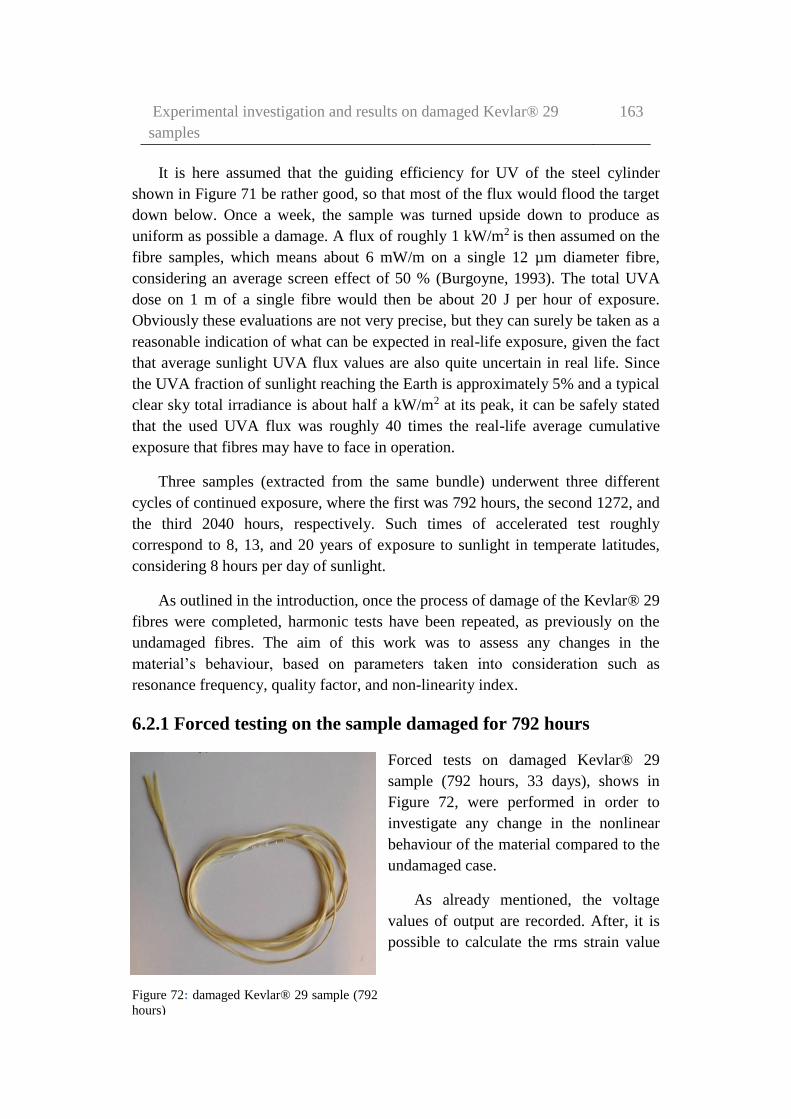
Experimental investigation and results on damaged Kevlar® 29
samples
163
It is here assumed that the guiding efficiency for UV of the steel cylinder
shown in Figure 71 be rather good, so that most of the flux would flood the target
down below. Once a week, the sample was turned upside down to produce as
uniform as possible a damage. A flux of roughly 1 kW/m2 is then assumed on the
fibre samples, which means about 6 mW/m on a single 12 µm diameter fibre,
considering an average screen effect of 50 % (Burgoyne, 1993). The total UVA
dose on 1 m of a single fibre would then be about 20 J per hour of exposure.
Obviously these evaluations are not very precise, but they can surely be taken as a
reasonable indication of what can be expected in real-life exposure, given the fact
that average sunlight UVA flux values are also quite uncertain in real life. Since
the UVA fraction of sunlight reaching the Earth is approximately 5% and a typical
clear sky total irradiance is about half a kW/m2 at its peak, it can be safely stated
that the used UVA flux was roughly 40 times the real-life average cumulative
exposure that fibres may have to face in operation.
Three samples (extracted from the same bundle) underwent three different
cycles of continued exposure, where the first was 792 hours, the second 1272, and
the third 2040 hours, respectively. Such times of accelerated test roughly
correspond to 8, 13, and 20 years of exposure to sunlight in temperate latitudes,
considering 8 hours per day of sunlight.
As outlined in the introduction, once the process of damage of the Kevlar® 29
fibres were completed, harmonic tests have been repeated, as previously on the
undamaged fibres. The aim of this work was to assess any changes in the
material’s behaviour, based on parameters taken into consideration such as
resonance frequency, quality factor, and non-linearity index.
6.2.1 Forced testing on the sample damaged for 792 hours
Forced tests on damaged Kevlar® 29
sample (792 hours, 33 days), shows in
Figure 72, were performed in order to
investigate any change in the nonlinear
behaviour of the material compared to the
undamaged case.
As already mentioned, the voltage
values of output are recorded. After, it is
possible to calculate the rms strain value
Figure 72: damaged Kevlar® 29 sample (792
hours)

164 Elena Pinotti – Dynamic characterization of high-performance
materials for application to cultural heritage
by using a conversion factor evaluated during the calibration of the photodiode
(measurement sensitivity S=70 mV/µ, in this case).
The frequency interval taken into consideration has an amplitude of 0.590 Hz,
roughly centred on the resonance frequency of the system. Moreover, the step
increment of the excitation frequency is always equal to 0.010 Hz.
In the following Table 14 are reported the strain values calculated from the
numerical data acquired during the forced tests.
Table 14: strain values calculated from the numerical data acquired during the
forced tests.
2.0 [V] 3.0 [V] 4.0 [V] 5.0 [V]
Freq. ε Freq. ε Freq. ε Freq. ε
[Hz] [RMS] [Hz] [RMS] [Hz] [RMS] [Hz] [RMS]
20.42 1.399E-6 20.42 2.425E-6 20.42 3.172E-6 20.42 4.104E-6
20.43 1.437E-6 20.43 2.519E-6 20.43 3.265E-6 20.43 4.160E-6
20.44 1.493E-6 20.44 2.612E-6 20.44 3.358E-6 20.44 4.216E-6
20.45 1.586E-6 20.45 2.668E-6 20.45 3.451E-6 20.45 4.291E-6
20.46 1.679E-6 20.46 2.705E-6 20.46 3.545E-6 20.46 4.384E-6
20.47 1.772E-6 20.47 2.761E-6 20.47 3.638E-6 20.47 4.478E-6
20.48 1.866E-6 20.48 2.799E-6 20.48 3.731E-6 20.48 4.571E-6
20.49 1.959E-6 20.49 2.892E-6 20.49 3.862E-6 20.49 4.664E-6
20.50 2.052E-6 20.50 2.985E-6 20.50 3.993E-6 20.50 4.757E-6
20.51 2.108E-6 20.51 3.041E-6 20.51 4.104E-6 20.51 4.851E-6
20.52 2.164E-6 20.52 3.078E-6 20.52 4.198E-6 20.52 5.000E-6
20.53 2.239E-6 20.53 3.172E-6 20.53 4.291E-6 20.53 5.149E-6
20.54 2.295E-6 20.54 3.265E-6 20.54 4.384E-6 20.54 5.317E-6
20.55 2.351E-6 20.55 3.358E-6 20.55 4.534E-6 20.55 5.504E-6
20.56 2.425E-6 20.56 3.489E-6 20.56 4.683E-6 20.56 5.690E-6
20.57 2.481E-6 20.57 3.619E-6 20.57 4.851E-6 20.57 5.877E-6
20.58 2.537E-6 20.58 3.731E-6 20.58 5.037E-6 20.58 6.101E-6
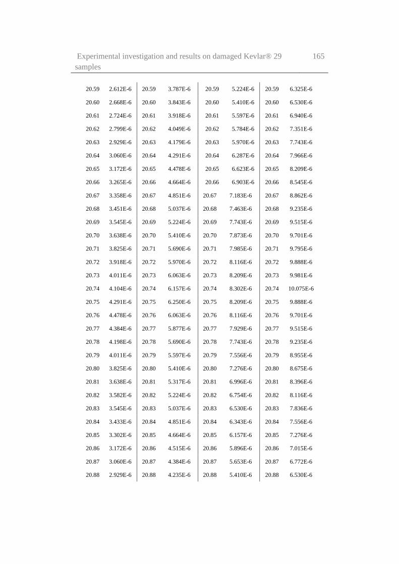
Experimental investigation and results on damaged Kevlar® 29
samples
165
20.59 2.612E-6 20.59 3.787E-6 20.59 5.224E-6 20.59 6.325E-6
20.60 2.668E-6 20.60 3.843E-6 20.60 5.410E-6 20.60 6.530E-6
20.61 2.724E-6 20.61 3.918E-6 20.61 5.597E-6 20.61 6.940E-6
20.62 2.799E-6 20.62 4.049E-6 20.62 5.784E-6 20.62 7.351E-6
20.63 2.929E-6 20.63 4.179E-6 20.63 5.970E-6 20.63 7.743E-6
20.64 3.060E-6 20.64 4.291E-6 20.64 6.287E-6 20.64 7.966E-6
20.65 3.172E-6 20.65 4.478E-6 20.65 6.623E-6 20.65 8.209E-6
20.66 3.265E-6 20.66 4.664E-6 20.66 6.903E-6 20.66 8.545E-6
20.67 3.358E-6 20.67 4.851E-6 20.67 7.183E-6 20.67 8.862E-6
20.68 3.451E-6 20.68 5.037E-6 20.68 7.463E-6 20.68 9.235E-6
20.69 3.545E-6 20.69 5.224E-6 20.69 7.743E-6 20.69 9.515E-6
20.70 3.638E-6 20.70 5.410E-6 20.70 7.873E-6 20.70 9.701E-6
20.71 3.825E-6 20.71 5.690E-6 20.71 7.985E-6 20.71 9.795E-6
20.72 3.918E-6 20.72 5.970E-6 20.72 8.116E-6 20.72 9.888E-6
20.73 4.011E-6 20.73 6.063E-6 20.73 8.209E-6 20.73 9.981E-6
20.74 4.104E-6 20.74 6.157E-6 20.74 8.302E-6 20.74 10.075E-6
20.75 4.291E-6 20.75 6.250E-6 20.75 8.209E-6 20.75 9.888E-6
20.76 4.478E-6 20.76 6.063E-6 20.76 8.116E-6 20.76 9.701E-6
20.77 4.384E-6 20.77 5.877E-6 20.77 7.929E-6 20.77 9.515E-6
20.78 4.198E-6 20.78 5.690E-6 20.78 7.743E-6 20.78 9.235E-6
20.79 4.011E-6 20.79 5.597E-6 20.79 7.556E-6 20.79 8.955E-6
20.80 3.825E-6 20.80 5.410E-6 20.80 7.276E-6 20.80 8.675E-6
20.81 3.638E-6 20.81 5.317E-6 20.81 6.996E-6 20.81 8.396E-6
20.82 3.582E-6 20.82 5.224E-6 20.82 6.754E-6 20.82 8.116E-6
20.83 3.545E-6 20.83 5.037E-6 20.83 6.530E-6 20.83 7.836E-6
20.84 3.433E-6 20.84 4.851E-6 20.84 6.343E-6 20.84 7.556E-6
20.85 3.302E-6 20.85 4.664E-6 20.85 6.157E-6 20.85 7.276E-6
20.86 3.172E-6 20.86 4.515E-6 20.86 5.896E-6 20.86 7.015E-6
20.87 3.060E-6 20.87 4.384E-6 20.87 5.653E-6 20.87 6.772E-6
20.88 2.929E-6 20.88 4.235E-6 20.88 5.410E-6 20.88 6.530E-6

166 Elena Pinotti – Dynamic characterization of high-performance
materials for application to cultural heritage
20.89 2.799E-6 20.89 4.104E-6 20.89 5.224E-6 20.89 6.269E-6
20.90 2.817E-6 20.90 3.862E-6 20.90 5.037E-6 20.90 6.026E-6
20.91 2.668E-6 20.91 3.638E-6 20.91 4.851E-6 20.91 5.784E-6
20.92 2.519E-6 20.92 3.507E-6 20.92 4.664E-6 20.92 5.597E-6
20.93 2.425E-6 20.93 3.377E-6 20.93 4.478E-6 20.93 5.410E-6
20.94 2.332E-6 20.94 3.265E-6 20.94 4.291E-6 20.94 5.224E-6
20.95 2.239E-6 20.95 3.097E-6 20.95 4.160E-6 20.95 5.075E-6
20.96 2.164E-6 20.96 2.948E-6 20.96 4.049E-6 20.96 4.907E-6
20.97 2.108E-6 20.97 2.799E-6 20.97 3.918E-6 20.97 4.757E-6
20.98 2.052E-6 20.98 2.649E-6 20.98 3.769E-6 20.98 4.590E-6
20.99 1.940E-6 20.99 2.537E-6 20.99 3.619E-6 20.99 4.422E-6
21.00 1.810E-6 21.00 2.425E-6 21.00 3.489E-6 21.00 4.272E-6
21.01 1.679E-6 21.01 2.332E-6 21.01 3.358E-6 21.01 4.104E-6
6.0 [V] 7.0 [V] 8.0 [V] 9.0 [V] 10.0 [V]
Freq. ε Freq. ε Freq. Ε Freq. ε Freq. ε
[Hz] [RMS
]
[Hz] [RMS] [Hz] [RMS
]
[Hz] [RMS] [Hz] [RMS]
20.42 5.13E-6 20.42 6.06E-6 20.42 7.28E-6 20.42 8.39E-6 20.42 9.33E-6
20.43 5.22E-6 20.43 6.16E-6 20.43 7.43E-6 20.43 8.55E-6 20.43 9.61E-6
20.44 5.32E-6 20.44 6.25E-6 20.44 7.58E-6 20.44 8.69E-6 20.44 9.89E-6
20.45 5.41E-6 20.45 6.39E-6 20.45 7.74E-6 20.45 8.86E-6 20.45 1.17E-6
20.46 5.50E-6 20.46 6.55E-6 20.46 7.84E-6 20.46 8.99E-6 20.46 10.45E-6
20.47 5.63E-6 20.47 6.72E-6 20.47 7.93E-6 20.47 9.12E-6 20.47 10.67E-6
20.48 5.78E-6 20.48 6.85E-6 20.48 8.02E-6 20.48 9.24E-6 20.48 10.91E-6
20.49 5.88E-6 20.49 6.98E-6 20.49 8.25E-6 20.49 9.52E-6 20.49 11.04E-6
20.50 5.97E-6 20.50 7.09E-6 20.50 8.49E-6 20.50 9.79E-6 20.50 11.28E-6
20.51 6.06E-6 20.51 7.24E-6 20.51 8.68E-6 20.51 10.08E-6 20.51 11.53E-6
20.52 6.21E-6 20.52 7.39E-6 20.52 8.92E-6 20.52 10.39E-6 20.52 11.75E-6
20.53 6.53E-6 20.53 7.56E-6 20.53 9.16E-6 20.53 10.71E-6 20.53 12.13E-6
20.54 6.72E-6 20.54 7.79E-6 20.54 9.42E-6 20.54 11.01E-6 20.54 12.41E-6
20.55 6.96E-6 20.55 8.04E-6 20.55 9.89E-6 20.55 11.44E-6 20.55 12.69E-6
20.56 7.11E-6 20.56 8.30E-6 20.56 10.35E-6 20.56 11.88E-6 20.56 13.15E-6
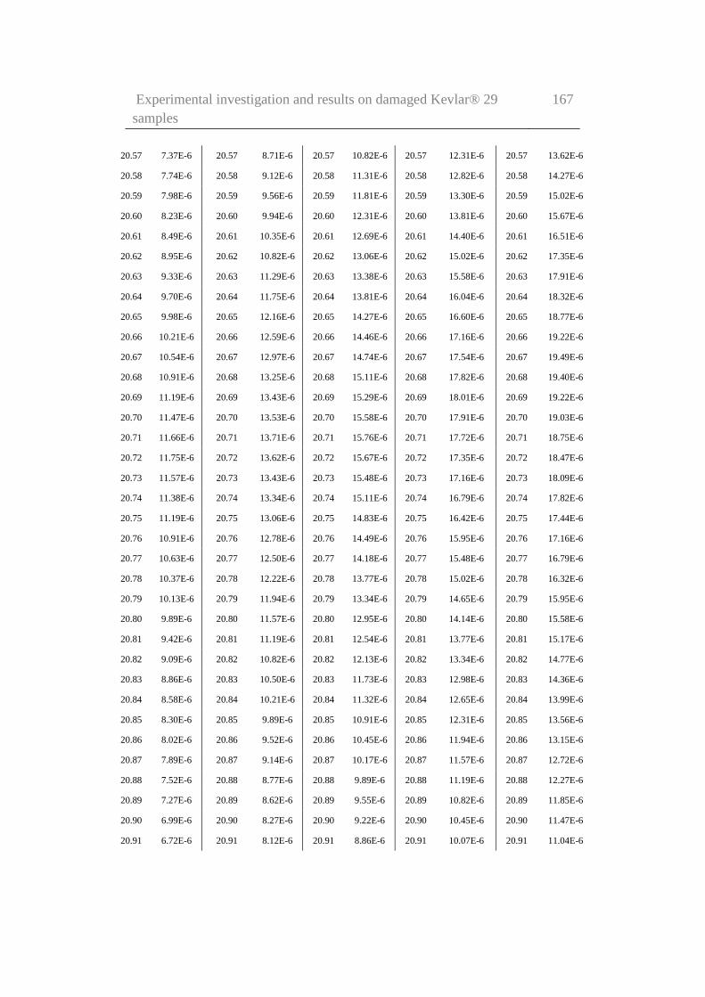
Experimental investigation and results on damaged Kevlar® 29
samples
167
20.57 7.37E-6 20.57 8.71E-6 20.57 10.82E-6 20.57 12.31E-6 20.57 13.62E-6
20.58 7.74E-6 20.58 9.12E-6 20.58 11.31E-6 20.58 12.82E-6 20.58 14.27E-6
20.59 7.98E-6 20.59 9.56E-6 20.59 11.81E-6 20.59 13.30E-6 20.59 15.02E-6
20.60 8.23E-6 20.60 9.94E-6 20.60 12.31E-6 20.60 13.81E-6 20.60 15.67E-6
20.61 8.49E-6 20.61 10.35E-6 20.61 12.69E-6 20.61 14.40E-6 20.61 16.51E-6
20.62 8.95E-6 20.62 10.82E-6 20.62 13.06E-6 20.62 15.02E-6 20.62 17.35E-6
20.63 9.33E-6 20.63 11.29E-6 20.63 13.38E-6 20.63 15.58E-6 20.63 17.91E-6
20.64 9.70E-6 20.64 11.75E-6 20.64 13.81E-6 20.64 16.04E-6 20.64 18.32E-6
20.65 9.98E-6 20.65 12.16E-6 20.65 14.27E-6 20.65 16.60E-6 20.65 18.77E-6
20.66 10.21E-6 20.66 12.59E-6 20.66 14.46E-6 20.66 17.16E-6 20.66 19.22E-6
20.67 10.54E-6 20.67 12.97E-6 20.67 14.74E-6 20.67 17.54E-6 20.67 19.49E-6
20.68 10.91E-6 20.68 13.25E-6 20.68 15.11E-6 20.68 17.82E-6 20.68 19.40E-6
20.69 11.19E-6 20.69 13.43E-6 20.69 15.29E-6 20.69 18.01E-6 20.69 19.22E-6
20.70 11.47E-6 20.70 13.53E-6 20.70 15.58E-6 20.70 17.91E-6 20.70 19.03E-6
20.71 11.66E-6 20.71 13.71E-6 20.71 15.76E-6 20.71 17.72E-6 20.71 18.75E-6
20.72 11.75E-6 20.72 13.62E-6 20.72 15.67E-6 20.72 17.35E-6 20.72 18.47E-6
20.73 11.57E-6 20.73 13.43E-6 20.73 15.48E-6 20.73 17.16E-6 20.73 18.09E-6
20.74 11.38E-6 20.74 13.34E-6 20.74 15.11E-6 20.74 16.79E-6 20.74 17.82E-6
20.75 11.19E-6 20.75 13.06E-6 20.75 14.83E-6 20.75 16.42E-6 20.75 17.44E-6
20.76 10.91E-6 20.76 12.78E-6 20.76 14.49E-6 20.76 15.95E-6 20.76 17.16E-6
20.77 10.63E-6 20.77 12.50E-6 20.77 14.18E-6 20.77 15.48E-6 20.77 16.79E-6
20.78 10.37E-6 20.78 12.22E-6 20.78 13.77E-6 20.78 15.02E-6 20.78 16.32E-6
20.79 10.13E-6 20.79 11.94E-6 20.79 13.34E-6 20.79 14.65E-6 20.79 15.95E-6
20.80 9.89E-6 20.80 11.57E-6 20.80 12.95E-6 20.80 14.14E-6 20.80 15.58E-6
20.81 9.42E-6 20.81 11.19E-6 20.81 12.54E-6 20.81 13.77E-6 20.81 15.17E-6
20.82 9.09E-6 20.82 10.82E-6 20.82 12.13E-6 20.82 13.34E-6 20.82 14.77E-6
20.83 8.86E-6 20.83 10.50E-6 20.83 11.73E-6 20.83 12.98E-6 20.83 14.36E-6
20.84 8.58E-6 20.84 10.21E-6 20.84 11.32E-6 20.84 12.65E-6 20.84 13.99E-6
20.85 8.30E-6 20.85 9.89E-6 20.85 10.91E-6 20.85 12.31E-6 20.85 13.56E-6
20.86 8.02E-6 20.86 9.52E-6 20.86 10.45E-6 20.86 11.94E-6 20.86 13.15E-6
20.87 7.89E-6 20.87 9.14E-6 20.87 10.17E-6 20.87 11.57E-6 20.87 12.72E-6
20.88 7.52E-6 20.88 8.77E-6 20.88 9.89E-6 20.88 11.19E-6 20.88 12.27E-6
20.89 7.27E-6 20.89 8.62E-6 20.89 9.55E-6 20.89 10.82E-6 20.89 11.85E-6
20.90 6.99E-6 20.90 8.27E-6 20.90 9.22E-6 20.90 10.45E-6 20.90 11.47E-6
20.91 6.72E-6 20.91 8.12E-6 20.91 8.86E-6 20.91 10.07E-6 20.91 11.04E-6
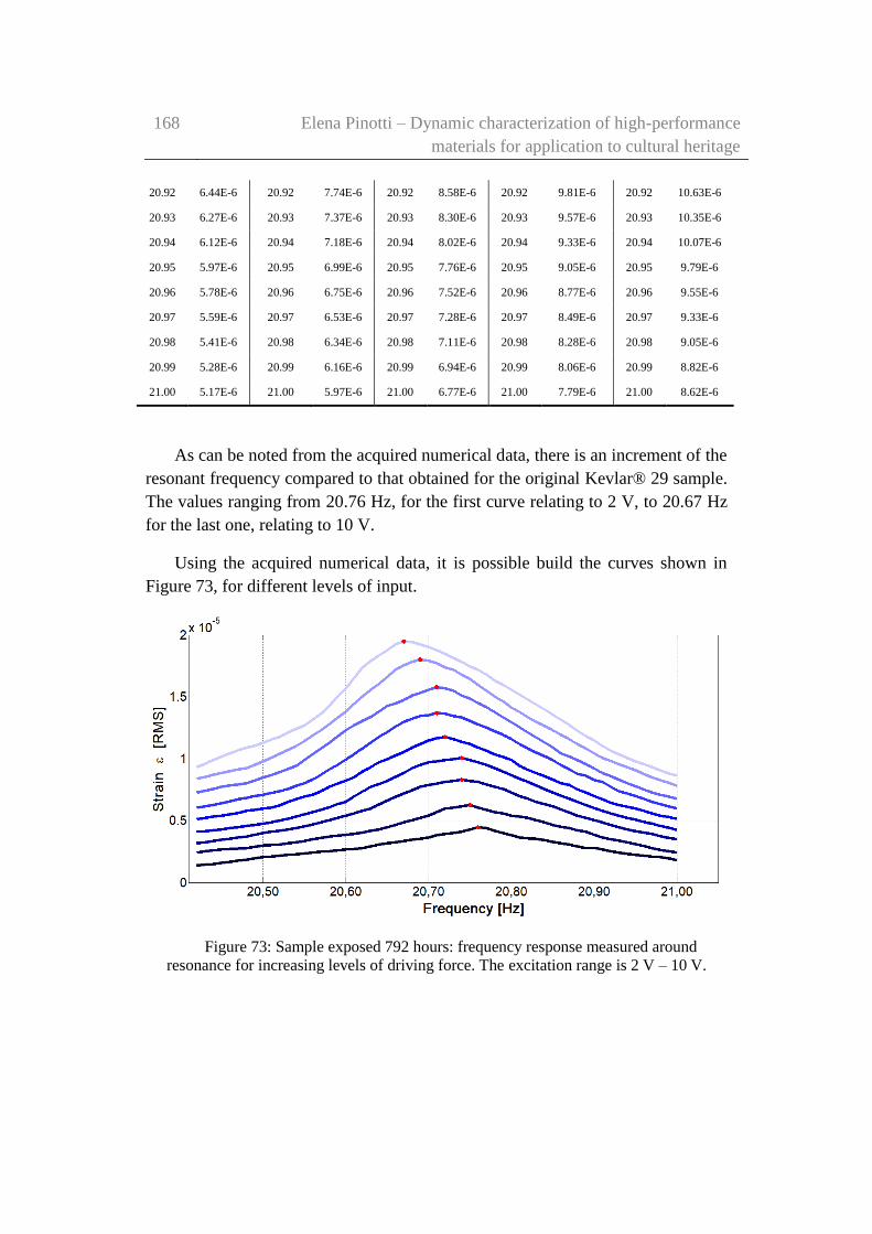
168 Elena Pinotti – Dynamic characterization of high-performance
materials for application to cultural heritage
20.92 6.44E-6 20.92 7.74E-6 20.92 8.58E-6 20.92 9.81E-6 20.92 10.63E-6
20.93 6.27E-6 20.93 7.37E-6 20.93 8.30E-6 20.93 9.57E-6 20.93 10.35E-6
20.94 6.12E-6 20.94 7.18E-6 20.94 8.02E-6 20.94 9.33E-6 20.94 10.07E-6
20.95 5.97E-6 20.95 6.99E-6 20.95 7.76E-6 20.95 9.05E-6 20.95 9.79E-6
20.96 5.78E-6 20.96 6.75E-6 20.96 7.52E-6 20.96 8.77E-6 20.96 9.55E-6
20.97 5.59E-6 20.97 6.53E-6 20.97 7.28E-6 20.97 8.49E-6 20.97 9.33E-6
20.98 5.41E-6 20.98 6.34E-6 20.98 7.11E-6 20.98 8.28E-6 20.98 9.05E-6
20.99 5.28E-6 20.99 6.16E-6 20.99 6.94E-6 20.99 8.06E-6 20.99 8.82E-6
21.00 5.17E-6 21.00 5.97E-6 21.00 6.77E-6 21.00 7.79E-6 21.00 8.62E-6
As can be noted from the acquired numerical data, there is an increment of the
resonant frequency compared to that obtained for the original Kevlar® 29 sample.
The values ranging from 20.76 Hz, for the first curve relating to 2 V, to 20.67 Hz
for the last one, relating to 10 V.
Using the acquired numerical data, it is possible build the curves shown in
Figure 73, for different levels of input.
Figure 73: Sample exposed 792 hours: frequency response measured around
resonance for increasing levels of driving force. The excitation range is 2 V – 10 V.

Experimental investigation and results on damaged Kevlar® 29
samples
169
According to the graph shown in Figure 73, also in this case there is a
nonlinear behaviour of the response. It is clear because increasing the voltage
input, the peak of the curves indicates that the resonance frequency tends to shift
towards values of the frequency lower.
For quantifying this non-linearity, was again used a backbone curve, which
represent the best approximation of the trend points, corresponding to the various
peaks of the curves.
By referring to the numerical data acquired for this sample, in Figure 74 is
shown the backbone curve obtained. In this way is possible to quantify the
nonlinear behaviour of the material under investigation.
Figure 74: sample exposed 792 hours: frequency response measured around
resonance for increasing levels of driving force. The excitation range is 2 V – 10 V. The
red dots highlight the maximum of the response curve and the dashed red line is the
estimated backbone response curve.
The cubic stiffness coefficient obtained in this case is equal to 𝜒 = −5.028 ∙
1011 𝑁 𝑚3⁄ .
Finally, the value of the ζ damping of the system was calculated applying the
half-power bandwidth method, and was computed for the 5 V response and was
estimated at 0.58% (Q= 86).

170 Elena Pinotti – Dynamic characterization of high-performance
materials for application to cultural heritage
6.2.2 Forced testing on the sample damaged for 1272 hours
The second sample investigated is a
Kevlar® 29 material exposed for 53 days
(1272 hours) to UV rays (Figure 75). A
set of forced tests was performed, and in
this case, the measurement's sensitivity
evaluated is equal to 90 mV/µ.
The frequencies range taken into
account during the tests has an amplitude
of 0.600 Hz, centred roughly on the
resonance frequency of the system.
Moreover, the increment step of the
frequency was chosen equal to 0.010 Hz.
In the following Table 15 are reported the strain values calculated from the
numerical data acquired during the forced tests.
Table 15: strain values calculated from the numerical data acquired during the forced
tests.
2.0 [V] 3.0 [V] 4.0 [V] 5.0 [V]
Freq. ε Freq. ε Freq. ε Freq. ε
[Hz] [RMS] [Hz] [RMS] [Hz] [RMS] [Hz] [RMS]
19.53 1.57E-6 19.53 2.24E-6 19.53 2.98E-6 19.53 3.81E-6
19.54 1.62E-6 19.54 2.32E-6 19.54 3.07E-6 19.54 3.93E-6
19.55 1.69E-6 19.55 2.41E-6 19.55 3.15E-6 19.55 4.03E-6
19.56 1.74E-6 19.56 2.49E-6 19.56 3.23E-6 19.56 4.15E-6
19.57 1.79E-6 19.57 2.57E-6 19.57 3.35E-6 19.57 4.26E-6
19.58 1.84E-6 19.58 2.65E-6 19.58 3.47E-6 19.58 4.36E-6
19.59 1.91E-6 19.59 2.74E-6 19.59 3.56E-6 19.59 4.48E-6
19.60 1.96E-6 19.60 2.79E-6 19.60 3.65E-6 19.60 4.64E-6
19.61 2.02E-6 19.61 2.84E-6 19.61 3.73E-6 19.61 4.81E-6
19.62 2.07E-6 19.62 2.90E-6 19.62 3.81E-6 19.62 4.96E-6
19.63 2.12E-6 19.63 2.98E-6 19.63 3.95E-6 19.63 5.17E-6
Figure 75: damaged Kevlar® 29 sample
(1272 hours)
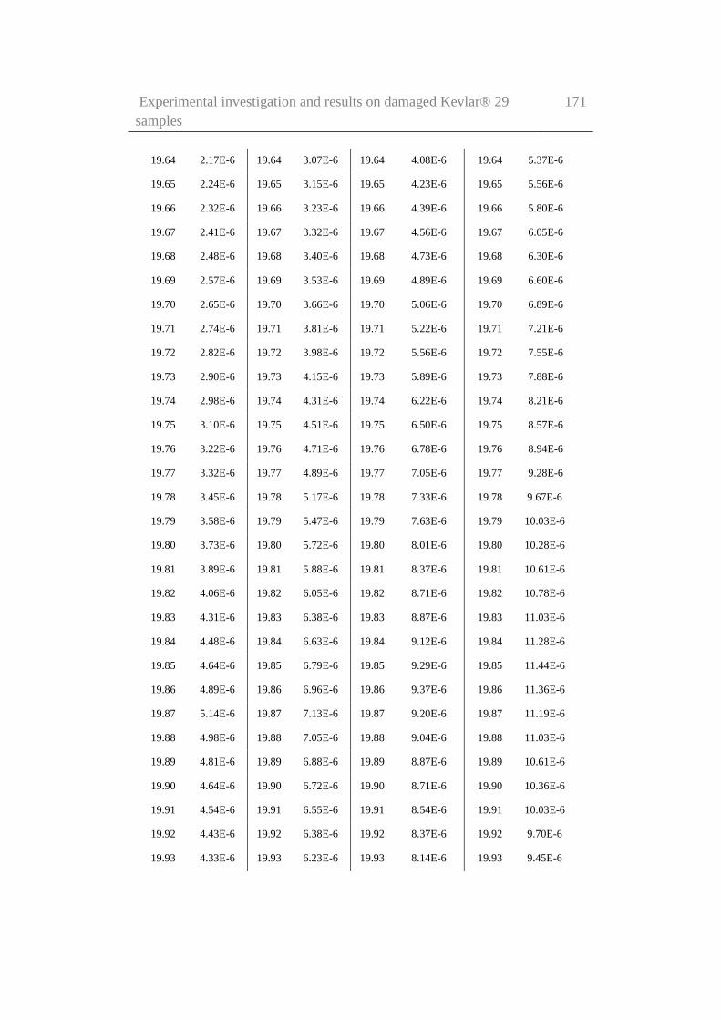
Experimental investigation and results on damaged Kevlar® 29
samples
171
19.64 2.17E-6 19.64 3.07E-6 19.64 4.08E-6 19.64 5.37E-6
19.65 2.24E-6 19.65 3.15E-6 19.65 4.23E-6 19.65 5.56E-6
19.66 2.32E-6 19.66 3.23E-6 19.66 4.39E-6 19.66 5.80E-6
19.67 2.41E-6 19.67 3.32E-6 19.67 4.56E-6 19.67 6.05E-6
19.68 2.48E-6 19.68 3.40E-6 19.68 4.73E-6 19.68 6.30E-6
19.69 2.57E-6 19.69 3.53E-6 19.69 4.89E-6 19.69 6.60E-6
19.70 2.65E-6 19.70 3.66E-6 19.70 5.06E-6 19.70 6.89E-6
19.71 2.74E-6 19.71 3.81E-6 19.71 5.22E-6 19.71 7.21E-6
19.72 2.82E-6 19.72 3.98E-6 19.72 5.56E-6 19.72 7.55E-6
19.73 2.90E-6 19.73 4.15E-6 19.73 5.89E-6 19.73 7.88E-6
19.74 2.98E-6 19.74 4.31E-6 19.74 6.22E-6 19.74 8.21E-6
19.75 3.10E-6 19.75 4.51E-6 19.75 6.50E-6 19.75 8.57E-6
19.76 3.22E-6 19.76 4.71E-6 19.76 6.78E-6 19.76 8.94E-6
19.77 3.32E-6 19.77 4.89E-6 19.77 7.05E-6 19.77 9.28E-6
19.78 3.45E-6 19.78 5.17E-6 19.78 7.33E-6 19.78 9.67E-6
19.79 3.58E-6 19.79 5.47E-6 19.79 7.63E-6 19.79 10.03E-6
19.80 3.73E-6 19.80 5.72E-6 19.80 8.01E-6 19.80 10.28E-6
19.81 3.89E-6 19.81 5.88E-6 19.81 8.37E-6 19.81 10.61E-6
19.82 4.06E-6 19.82 6.05E-6 19.82 8.71E-6 19.82 10.78E-6
19.83 4.31E-6 19.83 6.38E-6 19.83 8.87E-6 19.83 11.03E-6
19.84 4.48E-6 19.84 6.63E-6 19.84 9.12E-6 19.84 11.28E-6
19.85 4.64E-6 19.85 6.79E-6 19.85 9.29E-6 19.85 11.44E-6
19.86 4.89E-6 19.86 6.96E-6 19.86 9.37E-6 19.86 11.36E-6
19.87 5.14E-6 19.87 7.13E-6 19.87 9.20E-6 19.87 11.19E-6
19.88 4.98E-6 19.88 7.05E-6 19.88 9.04E-6 19.88 11.03E-6
19.89 4.81E-6 19.89 6.88E-6 19.89 8.87E-6 19.89 10.61E-6
19.90 4.64E-6 19.90 6.72E-6 19.90 8.71E-6 19.90 10.36E-6
19.91 4.54E-6 19.91 6.55E-6 19.91 8.54E-6 19.91 10.03E-6
19.92 4.43E-6 19.92 6.38E-6 19.92 8.37E-6 19.92 9.70E-6
19.93 4.33E-6 19.93 6.23E-6 19.93 8.14E-6 19.93 9.45E-6
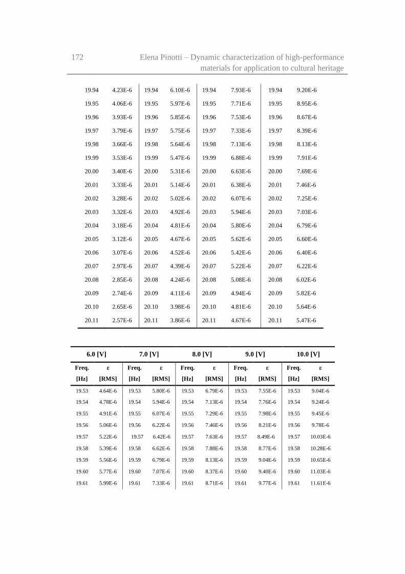
172 Elena Pinotti – Dynamic characterization of high-performance
materials for application to cultural heritage
19.94 4.23E-6 19.94 6.10E-6 19.94 7.93E-6 19.94 9.20E-6
19.95 4.06E-6 19.95 5.97E-6 19.95 7.71E-6 19.95 8.95E-6
19.96 3.93E-6 19.96 5.85E-6 19.96 7.53E-6 19.96 8.67E-6
19.97 3.79E-6 19.97 5.75E-6 19.97 7.33E-6 19.97 8.39E-6
19.98 3.66E-6 19.98 5.64E-6 19.98 7.13E-6 19.98 8.13E-6
19.99 3.53E-6 19.99 5.47E-6 19.99 6.88E-6 19.99 7.91E-6
20.00 3.40E-6 20.00 5.31E-6 20.00 6.63E-6 20.00 7.69E-6
20.01 3.33E-6 20.01 5.14E-6 20.01 6.38E-6 20.01 7.46E-6
20.02 3.28E-6 20.02 5.02E-6 20.02 6.07E-6 20.02 7.25E-6
20.03 3.32E-6 20.03 4.92E-6 20.03 5.94E-6 20.03 7.03E-6
20.04 3.18E-6 20.04 4.81E-6 20.04 5.80E-6 20.04 6.79E-6
20.05 3.12E-6 20.05 4.67E-6 20.05 5.62E-6 20.05 6.60E-6
20.06 3.07E-6 20.06 4.52E-6 20.06 5.42E-6 20.06 6.40E-6
20.07 2.97E-6 20.07 4.39E-6 20.07 5.22E-6 20.07 6.22E-6
20.08 2.85E-6 20.08 4.24E-6 20.08 5.08E-6 20.08 6.02E-6
20.09 2.74E-6 20.09 4.11E-6 20.09 4.94E-6 20.09 5.82E-6
20.10 2.65E-6 20.10 3.98E-6 20.10 4.81E-6 20.10 5.64E-6
20.11 2.57E-6 20.11 3.86E-6 20.11 4.67E-6 20.11 5.47E-6
6.0 [V] 7.0 [V] 8.0 [V] 9.0 [V] 10.0 [V]
Freq. ε Freq. ε Freq. ε Freq. ε Freq. ε
[Hz] [RMS] [Hz] [RMS] [Hz] [RMS] [Hz] [RMS] [Hz] [RMS]
19.53 4.64E-6 19.53 5.80E-6 19.53 6.79E-6 19.53 7.55E-6 19.53 9.04E-6
19.54 4.78E-6 19.54 5.94E-6 19.54 7.13E-6 19.54 7.76E-6 19.54 9.24E-6
19.55 4.91E-6 19.55 6.07E-6 19.55 7.29E-6 19.55 7.98E-6 19.55 9.45E-6
19.56 5.06E-6 19.56 6.22E-6 19.56 7.46E-6 19.56 8.21E-6 19.56 9.78E-6
19.57 5.22E-6 19.57 6.42E-6 19.57 7.63E-6 19.57 8.49E-6 19.57 10.03E-6
19.58 5.39E-6 19.58 6.62E-6 19.58 7.88E-6 19.58 8.77E-6 19.58 10.28E-6
19.59 5.56E-6 19.59 6.79E-6 19.59 8.13E-6 19.59 9.04E-6 19.59 10.65E-6
19.60 5.77E-6 19.60 7.07E-6 19.60 8.37E-6 19.60 9.40E-6 19.60 11.03E-6
19.61 5.99E-6 19.61 7.33E-6 19.61 8.71E-6 19.61 9.77E-6 19.61 11.61E-6

Experimental investigation and results on damaged Kevlar® 29
samples
173
19.62 6.22E-6 19.62 7.63E-6 19.62 9.04E-6 19.62 10.19E-6 19.62 12.27E-6
19.63 6.47E-6 19.63 7.85E-6 19.63 9.37E-6 19.63 10.65E-6 19.63 12.69E-6
19.64 6.72E-6 19.64 8.19E-6 19.64 9.75E-6 19.64 11.09E-6 19.64 13.18E-6
19.65 6.97E-6 19.65 8.46E-6 19.65 10.13E-6 19.65 11.61E-6 19.65 13.59E-6
19.66 7.25E-6 19.66 8.79E-6 19.66 10.53E-6 19.66 12.24E-6 19.66 14.09E-6
19.67 7.53E-6 19.67 9.12E-6 19.67 11.08E-6 19.67 12.87E-6 19.67 14.84E-6
19.68 7.79E-6 19.68 9.45E-6 19.68 11.57E-6 19.68 13.52E-6 19.68 15.59E-6
19.69 8.16E-6 19.69 9.83E-6 19.69 12.11E-6 19.69 14.09E-6 19.69 16.58E-6
19.70 8.52E-6 19.70 10.23E-6 19.70 12.65E-6 19.70 14.68E-6 19.70 17.76E-6
19.71 8.87E-6 19.71 10.61E-6 19.71 13.20E-6 19.71 15.53E-6 19.71 18.24E-6
19.72 9.34E-6 19.72 11.14E-6 19.72 13.85E-6 19.72 15.84E-6 19.72 18.91E-6
19.73 9.80E-6 19.73 11.68E-6 19.73 14.43E-6 19.73 16.50E-6 19.73 19.24E-6
19.74 10.28E-6 19.74 12.19E-6 19.74 14.93E-6 19.74 17.16E-6 19.74 19.57E-6
19.75 10.69E-6 19.75 12.77E-6 19.75 15.42E-6 19.75 17.75E-6 19.75 19.90E-6
19.76 11.03E-6 19.76 13.35E-6 19.76 15.92E-6 19.76 18.08E-6 19.76 20.23E-6
19.77 11.53E-6 19.77 13.76E-6 19.77 16.34E-6 19.77 18.41E-6 19.77 20.56E-6
19.78 11.86E-6 19.78 14.09E-6 19.78 16.67E-6 19.78 18.66E-6 19.78 20.89E-6
19.79 12.11E-6 19.79 14.34E-6 19.79 16.92E-6 19.79 18.99E-6 19.79 20.81E-6
19.80 12.36E-6 19.80 14.68E-6 19.80 17.16E-6 19.80 18.74E-6 19.80 20.48E-6
19.81 12.52E-6 19.81 14.84E-6 19.81 16.99E-6 19.81 18.49E-6 19.81 20.15E-6
19.82 12.85E-6 19.82 15.01E-6 19.82 16.78E-6 19.82 18.24E-6 19.82 19.98E-6
19.83 13.10E-6 19.83 14.76E-6 19.83 16.58E-6 19.83 17.91E-6 19.83 19.49E-6
19.84 12.94E-6 19.84 14.51E-6 19.84 16.42E-6 19.84 17.66E-6 19.84 19.15E-6
19.85 12.77E-6 19.85 14.26E-6 19.85 16.09E-6 19.85 17.25E-6 19.85 18.77E-6
19.86 12.60E-6 19.86 14.01E-6 19.86 15.75E-6 19.86 16.83E-6 19.86 18.41E-6
19.87 12.35E-6 19.87 13.76E-6 19.87 15.42E-6 19.87 16.42E-6 19.87 18.01E-6
19.88 12.06E-6 19.88 13.52E-6 19.88 15.09E-6 19.88 16.02E-6 19.88 17.63E-6
19.89 11.76E-6 19.89 13.15E-6 19.89 14.76E-6 19.89 15.64E-6 19.89 17.25E-6
19.90 11.44E-6 19.90 12.79E-6 19.90 14.43E-6 19.90 15.26E-6 19.90 16.79E-6
19.91 11.16E-6 19.91 12.44E-6 19.91 14.09E-6 19.91 14.84E-6 19.91 16.37E-6
19.92 10.88E-6 19.92 12.16E-6 19.92 13.69E-6 19.92 14.43E-6 19.92 15.92E-6
19.93 10.61E-6 19.93 11.87E-6 19.93 13.32E-6 19.93 14.01E-6 19.93 15.51E-6
19.94 10.32E-6 19.94 11.61E-6 19.94 12.94E-6 19.94 13.77E-6 19.94 15.21E-6
19.95 10.02E-6 19.95 11.28E-6 19.95 12.70E-6 19.95 13.52E-6 19.95 14.68E-6
19.96 9.70E-6 19.96 10.95E-6 19.96 12.32E-6 19.96 13.27E-6 19.96 14.26E-6

174 Elena Pinotti – Dynamic characterization of high-performance
materials for application to cultural heritage
19.97 9.42E-6 19.97 10.61E-6 19.97 12.02E-6 19.97 12.97E-6 19.97 13.85E-6
19.98 9.14E-6 19.98 10.33E-6 19.98 11.74E-6 19.98 12.67E-6 19.98 13.43E-6
19.99 8.87E-6 19.99 10.05E-6 19.99 11.41E-6 19.99 12.35E-6 19.99 13.10E-6
20.00 8.66E-6 20.00 9.78E-6 20.00 11.11E-6 20.00 12.07E-6 20.00 12.77E-6
20.01 8.44E-6 20.01 9.54E-6 20.01 10.85E-6 20.01 11.79E-6 20.01 12.44E-6
20.02 8.21E-6 20.02 9.29E-6 20.02 10.56E-6 20.02 11.53E-6 20.02 12.07E-6
20.03 7.99E-6 20.03 9.04E-6 20.03 10.28E-6 20.03 11.24E-6 20.03 11.74E-6
20.04 7.78E-6 20.04 8.76E-6 20.04 9.98E-6 20.04 10.96E-6 20.04 11.36E-6
20.05 7.55E-6 20.05 8.47E-6 20.05 9.67E-6 20.05 10.69E-6 20.05 11.11E-6
20.06 7.25E-6 20.06 8.21E-6 20.06 9.37E-6 20.06 10.45E-6 20.06 10.86E-6
20.07 6.95E-6 20.07 8.01E-6 20.07 9.12E-6 20.07 10.19E-6 20.07 10.69E-6
20.08 6.79E-6 20.08 7.81E-6 20.08 8.87E-6 20.08 9.95E-6 20.08 10.36E-6
20.09 6.55E-6 20.09 7.63E-6 20.09 8.62E-6 20.09 9.70E-6 20.09 10.12E-6
20.10 6.47E-6 20.10 7.49E-6 20.10 8.43E-6 20.10 9.45E-6 20.10 9.87E-6
20.11 6.39E-6 20.11 7.36E-6 20.11 8.23E-6 20.11 9.20E-6 20.11 9.67E-6
Using the acquired numerical data, it is possible build the curves shown in Figure
76, for different levels of input.
Figure 76: sample exposed 1272 hours: frequency response measured around
resonance for increasing levels of driving force. The excitation range is 2 V – 10 V.

Experimental investigation and results on damaged Kevlar® 29
samples
175
As can be noted from the acquired numerical data, there is an increment of the
resonant frequency compared to that obtained for the first level of damaging of
the Kevlar® 29 sample. The values ranges from 19.87 Hz, for the first curve
relating to 2 V, to 19.78 Hz for the last one, relating to 10 V.
By referring to the numerical data acquired for this second sample, in Figure
77 is shown the backbone curve obtained. In this way is also possible to quantify
the nonlinear behaviour of the material under investigation.
Figure 77: sample exposed 1272 hours: frequency response measured around
resonance for increasing levels of driving force. The excitation range is 2 V – 10 V. The
red dots highlight the maximum of the response curve and the dashed red line is the
estimated backbone response curve.
The cubic stiffness coefficient obtained in this case is equal to 𝜒 = −5.567 ∙
1011 𝑁 𝑚3⁄ .
Finally, the value of the ζ damping of the system was calculated applying the
half-power bandwidth method, and was computed for the 5 V response, and was
estimated at 0.66% (Q= 76).

176 Elena Pinotti – Dynamic characterization of high-performance
materials for application to cultural heritage
6.2.3 Forced testing on the sample damaged for 2040 hours
The third sample investigated is a
para-aramid material exposed for 85 days
(2040 hours) to UV rays (Figure 78). A
set of forced tests was performed, and in
this case, the measurement's sensitivity
evaluated is equal to 100 mV/µ.
The frequency range taken into
account during the tests has an amplitude
of 0.66 Hz, centred roughly on the
resonance frequency of the system.
Moreover, the increment step of the
frequency was chosen equal to 0.010 Hz.
In the following Table 16 are reported the strain values calculated from the
numerical data acquired during the forced tests.
Table 16: strain values calculated from the numerical data acquired during the forced
tests.
2.0 [V] 3.0 [V] 4.0 [V] 5.0 [V]
Freq. ε Freq. ε Freq. ε Freq. ε
[Hz] [RMS] [Hz] [RMS] [Hz] [RMS] [Hz] [RMS]
19.61 0.52E-6 19.61 1.34E-6 19.61 2.09E-6 19.61 3.13E-6
19.62 0.59E-6 19.62 1.42E-6 19.62 2.24E-6 19.62 3.28E-6
19.63 0.67E-6 19.63 1.49E-6 19.63 2.39E-6 19.63 3.43E-6
19.64 0.75E-6 19.64 1.57E-6 19.64 2.54E-6 19.64 3.58E-6
19.65 0.82E-6 19.65 1.64E-6 19.65 2.69E-6 19.65 3.73E-6
19.66 0.89E-6 19.66 1.72E-6 19.66 2.84E-6 19.66 3.88E-6
19.67 0.97E-6 19.67 1.87E-6 19.67 2.99E-6 19.67 4.03E-6
19.68 1.05E-6 19.68 2.02E-6 19.68 3.13E-6 19.68 4.18E-6
Figure 78: damaged Kevlar® 29 sample
(2040 hours)

Experimental investigation and results on damaged Kevlar® 29
samples
177
19.69 1.12E-6 19.69 2.16E-6 19.69 3.28E-6 19.69 4.33E-6
19.70 1.19E-6 19.70 2.24E-6 19.70 3.43E-6 19.70 4.48E-6
19.71 1.27E-6 19.71 2.39E-6 19.71 3.58E-6 19.71 4.63E-6
19.72 1.34E-6 19.72 2.46E-6 19.72 3.73E-6 19.72 4.78E-6
19.73 1.42E-6 19.73 2.61E-6 19.73 3.88E-6 19.73 4.93E-6
19.74 1.57E-6 19.74 2.76E-6 19.74 4.03E-6 19.74 5.08E-6
19.75 1.72E-6 19.75 2.84E-6 19.75 4.21E-6 19.75 5.22E-6
19.76 1.87E-6 19.76 2.91E-6 19.76 4.36E-6 19.76 5.37E-6
19.77 2.02E-6 19.77 2.98E-6 19.77 4.51E-6 19.77 5.67E-6
19.78 2.16E-6 19.78 3.13E-6 19.78 4.66E-6 19.78 5.97E-6
19.79 2.31E-6 19.79 3.21E-6 19.79 4.81E-6 19.79 6.27E-6
19.80 2.43E-6 19.80 3.36E-6 19.80 4.95E-6 19.80 6.57E-6
19.81 2.51E-6 19.81 3.51E-6 19.81 5.18E-6 19.81 6.87E-6
19.82 2.57E-6 19.82 3.66E-6 19.82 5.40E-6 19.82 7.16E-6
19.83 2.64E-6 19.83 3.81E-6 19.83 5.66E-6 19.83 7.46E-6
19.84 2.73E-6 19.84 4.03E6 19.84 5.89E-6 19.84 7.76E-6
19.85 2.81E-6 19.85 4.25E-6 19.85 6.12E-6 19.85 8.21E-6
19.86 2.97E-6 19.86 4.48E-6 19.86 6.37E-6 19.86 8.51E-6
19.87 3.13E-6 19.87 4.70E-6 19.87 6.79E-6 19.87 8.81E-6
19.88 3.21E-6 19.88 4.93E-6 19.88 7.16E-6 19.88 9.10E-6
19.89 3.28E-6 19.89 5.15E-6 19.89 7.34E-6 19.89 9.40E-6
19.90 3.52E-6 19.90 5.37E-6 19.90 7.69E-6 19.90 9.70E-6
19.91 3.76E-6 19.91 5.59E-6 19.91 7.98E-6 19.91 10.00E-6
19.92 3.93E-6 19.92 5.82E-6 19.92 8.36E-6 19.92 10.31E-6
19.93 4.10E-6 19.93 6.04E-6 19.93 8.66E-6 19.93 10.64E-6
19.94 4.22E-6 19.94 6.27E-6 19.94 8.84E-6 19.94 10.94E-6
19.95 4.36E-6 19.95 6.49E-6 19.95 9.03E-6 19.95 11.19E-6
19.96 4.46E-6 19.96 6.64E-6 19.96 9.13E-6 19.96 11.31E-6
19.97 4.55E-6 19.97 6.910E-6 19.97 9.224E-6 19.97 11.48E-6
19.98 4.70E-6 19.98 7.060E-6 19.98 9.403E-6 19.98 11.40E-6

178 Elena Pinotti – Dynamic characterization of high-performance
materials for application to cultural heritage
19.99 4.85E-6 19.99 7.164E-6 19.99 9.522E-6 19.99 11.37E-6
20.00 4.93E-6 20.00 7.343E-6 20.00 9.478E-6 20.00 11.21E-6
20.01 5.08E-6 20.01 7.299E-6 20.01 9.299E-6 20.01 11.05E-6
20.02 5.03E-6 20.02 7.194E-6 20.02 9.104E-6 20.02 10.84E-6
20.03 4.97E-6 20.03 7.090E-6 20.03 9.030E-6 20.03 10.63E-6
20.04 4.85E-6 20.04 6.940E-6 20.04 8.881E-6 20.04 10.46E-6
20.05 4.70E-6 20.05 6.866E-6 20.05 8.627E-6 20.05 10.29E-6
20.06 4.59E-6 20.06 6.612E-6 20.06 8.418E-6 20.06 10.08E-6
20.07 4.55E-6 20.07 6.493E-6 20.07 8.179E-6 20.07 9.77E-6
20.08 4.43E-6 20.08 6.343E-6 20.08 8.000E-6 20.08 9.48E-6
20.09 4.33E-6 20.09 6.194E-6 20.09 7.731E-6 20.09 9.18E-6
20.10 4.21E-6 20.10 6.045E-6 20.10 7.463E-6 20.10 8.88E-6
20.11 4.07E-6 20.11 5.896E-6 20.11 7.179E-6 20.11 8.58E-6
20.12 3.95E-6 20.12 5.672E-6 20.12 6.910E-6 20.12 8.28E-6
20.13 3.85E-6 20.13 5.522E-6 20.13 6.642E-6 20.13 7.98E-6
20.14 3.69E-6 20.14 5.224E-6 20.14 6.463E-6 20.14 7.76E-6
20.15 3.52E-6 20.15 5.075E-6 20.15 6.269E-6 20.15 7.46E-6
20.16 3.36E-6 20.16 4.925E-6 20.16 6.045E-6 20.16 7.16E-6
20.17 3.19E-6 20.17 4.627E-6 20.17 5.821E-6 20.17 6.87E-6
20.18 3.06E-6 20.18 4.328E-6 20.18 5.597E-6 20.18 6.72E-6
20.19 2.93E-6 20.19 4.104E-6 20.19 5.224E-6 20.19 6.42E-6
20.20 2.76E-6 20.20 3.881E-6 20.20 5.000E-6 20.20 6.12E-6
20.21 2.61E-6 20.21 3.582E-6 20.21 4.776E-6 20.21 5.97E-6
20.22 2.46E-6 20.22 3.433E-6 20.22 4.552E-6 20.22 5.67E-6
20.23 2.31E-6 20.23 3.284E-6 20.23 4.328E-6 20.23 5.37E-6
20.24 2.16E-6 20.24 3.134E-6 20.24 4.104E-6 20.24 5.08E-6
20.25 2.02E-6 20.25 2.985E-6 20.25 3.881E-6 20.25 4.77E-6
20.26 1.87E-6 20.26 2.836E-6 20.26 3.657E-6 20.26 4.48E-6
20.27 1.716E-6 20.27 2.687E-6 20.27 3.433E-6 20.27 4.179E-6

Experimental investigation and results on damaged Kevlar® 29
samples
179
6.0 [V] 7.0 [V] 8.0 [V] 9.0 [V] 10.0 [V]
Freq. ε Freq. ε Freq. Ε Freq. ε Freq. ε
[Hz] [RMS] [Hz] [RMS] [Hz] [RMS] [Hz] [RMS] [Hz] [RMS]
19.61 4.33E-6 19.61 4.93E-6 19.61 5.79E-6 19.61 6.81E-6 19.61 8.28E-6
19.62 4.45E-6 19.62 5.08E-6 19.62 5.97E-6 19.62 6.98E-6 19.62 8.51E-6
19.63 4.58E-6 19.63 5.22E-6 19.63 6.15E-6 19.63 7.16E-6 19.63 8.73E-6
19.64 4.70E-6 19.64 5.37E-6 19.64 6.34E-6 19.64 7.39E-6 19.64 9.03E-6
19.65 4.81E-6 19.65 5.52E-6 19.65 6.54E-6 19.65 7.59E-6 19.65 9.37E-6
19.66 4.89E-6 19.66 5.67E-6 19.66 6.73E-6 19.66 7.85E-6 19.66 9.73E-6
19.67 4.98E-6 19.67 5.82E-6 19.67 6.93E-6 19.67 8.13E-6 19.67 10.12E-6
19.68 5.15E-6 19.68 5.97E-6 19.68 7.12E-6 19.68 8.43E-6 19.68 10.51E-6
19.69 5.31E-6 19.69 6.12E-6 19.69 7.31E-6 19.69 8.70E-6 19.69 10.87E-6
19.70 5.49E-6 19.70 6.27E-6 19.70 7.54E-6 19.70 9.02E-6 19.70 11.34E-6
19.71 5.66E-6 19.71 6.57E-6 19.71 7.85E-6 19.71 9.37E-6 19.71 11.82E-6
19.72 5.82E-6 19.72 6.87E-6 19.72 8.18E-6 19.72 9.67E-6 19.72 12.31E-6
19.73 6.04E-6 19.73 7.16E-6 19.73 8.43E-6 19.73 10.15E-6 19.73 12.76E-6
19.74 6.27E-6 19.74 7.31E-6 19.74 8.88E-6 19.74 10.58E-6 19.74 13.22E-6
19.75 6.49E-6 19.75 7.61E-6 19.75 9.29E-6 19.75 11.16E-6 19.75 14.06E-6
19.76 6.72E-6 19.76 7.91E-6 19.76 9.70E-6 19.76 11.72E-6 19.76 14.89E-6
19.77 6.97E-6 19.77 8.21E-6 19.77 10.15E-6 19.77 12.29E-6 19.77 15.52E-6
19.78 7.22E-6 19.78 8.66E-6 19.78 10.59E-6 19.78 12.89E-6 19.78 16.34E-6
19.79 7.54E-6 19.79 9.10E-6 19.79 11.10E-6 19.79 13.54E-6 19.79 16.97E-6
19.80 7.73E-6 19.80 9.40E-6 19.80 11.61E-6 19.80 14.15E-6 19.80 17.69E-6
19.81 8.15E-6 19.81 9.85E-6 19.81 12.16E-6 19.81 14.84E-6 19.81 18.40E-6
19.82 8.48E-6 19.82 10.29E-6 19.82 12.69E-6 19.82 15.66E-6 19.82 19.15E-6
19.83 8.88E-6 19.83 10.75E-6 19.83 13.33E-6 19.83 16.21E-6 19.83 19.63E-6
19.84 9.28E-6 19.84 11.19E-6 19.84 14.06E-6 19.84 16.94E-6 19.84 20.12E-6
19.85 9.78E-6 19.85 11.64E-6 19.85 14.55E-6 19.85 17.34E-6 19.85 20.39E-6
19.86 10.36E-6 19.86 12.09E-6 19.86 15.15E-6 19.86 17.88E-6 19.86 20.52E-6
19.87 10.75E-6 19.87 12.66E-6 19.87 15.57E-6 19.87 18.16E-6 19.87 20.72E-6
19.88 11.18E-6 19.88 13.22E-6 19.88 15.81E-6 19.88 18.33E-6 19.88 20.58E-6
19.89 11.64E-6 19.89 13.73E-6 19.89 16.05E-6 19.89 18.42E-6 19.89 20.52E-6
19.90 12.09E-6 19.90 14.18E-6 19.90 16.42E-6 19.90 18.28E-6 19.90 20.34E-6
19.91 12.34E-6 19.91 14.59E-6 19.91 16.64E-6 19.91 18.21E-6 19.91 20.07E-6
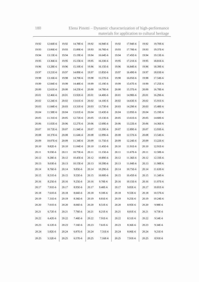
180 Elena Pinotti – Dynamic characterization of high-performance
materials for application to cultural heritage
19.92 12.66E-6 19.92 14.78E-6 19.92 16.94E-6 19.92 17.94E-6 19.92 19.70E-6
19.93 13.06E-6 19.93 15.00E-6 19.93 16.76E-6 19.93 17.70E-6 19.93 19.37E-6
19.94 13.13E-6 19.94 15.19E-6 19.94 16.64E-6 19.94 17.45E-6 19.94 19.13E-6
19.95 13.36E-6 19.95 15.15E-6 19.95 16.33E-6 19.95 17.21E-6 19.95 18.81E-6
19.96 13.28E-6 19.96 15.10E-6 19.96 16.15E-6 19.96 16.84E-6 19.96 18.39E-6
19.97 13.21E-6 19.97 14.89E-6 19.97 15.85E-6 19.97 16.49E-6 19.97 18.03E-6
19.98 13.16E-6 19.98 14.70E-6 19.98 15.57E-6 19.98 16.05E-6 19.98 17.54E-6
19.99 12.84E-6 19.99 14.48E-6 19.99 15.19E-6 19.99 15.67E-6 19.99 17.25E-6
20.00 12.61E-6 20.00 14.25E-6 20.00 14.78E-6 20.00 15.37E-6 20.00 16.78E-6
20.01 12.46E-6 20.01 13.92E-6 20.01 14.40E-6 20.01 14.98E-6 20.01 16.29E-6
20.02 12.24E-6 20.02 13.61E-6 20.02 14.10E-6 20.02 14.63E-6 20.02 15.91E-6
20.03 11.84E-6 20.03 13.31E-6 20.03 13.73E-6 20.03 14.29E-6 20.03 15.48E-6
20.04 11.58E-6 20.04 13.01E-6 20.04 13.43E-6 20.04 13.95E-6 20.04 15.19E-6
20.05 11.31E-6 20.05 12.72E-6 20.05 13.13E-6 20.05 13.61E-6 20.05 14.68E-6
20.06 11.02E-6 20.06 12.27E-6 20.06 12.69E-6 20.06 13.22E-6 20.06 14.36E-6
20.07 10.72E-6 20.07 11.94E-6 20.07 13.39E-6 20.07 12.89E-6 20.07 13.93E-6
20.08 10.37E-6 20.08 11.64E-6 20.08 12.09E-6 20.08 12.57E-6 20.08 13.54E-6
20.09 10.07E-6 20.09 11.34E-6 20.09 11.75E-6 20.09 12.24E-6 20.09 13.22E-6
20.10 9.82E-6 20.10 11.04E-6 20.10 11.45E-6 20.10 11.91E-6 20.10 12.91E-6
20.11 9.55E-6 20.11 10.75E-6 20.11 11.15E-6 20.11 11.67E-6 20.11 12.58E-6
20.12 9.28E-6 20.12 10.45E-6 20.12 10.89E-6 20.12 11.36E-6 20.12 12.33E-6
20.13 9.03E-6 20.13 10.15E-6 20.13 10.59E-6 20.13 11.04E-6 20.13 11.98E-6
20.14 8.76E-6 20.14 9.85E-6 20.14 10.29E-6 20.14 10.75E-6 20.14 11.63E-6
20.15 8.51E-6 20.15 9.55E-6 20.15 10.00E-6 20.15 10.45E-6 20.15 11.34E-6
20.16 8.25E-6 20.16 9.25E-6 20.16 9.70E-6 20.16 10.15E-6 20.16 11.07E-6
20.17 7.91E-6 20.17 8.95E-6 20.17 9.40E-6 20.17 9.85E-6 20.17 10.81E-6
20.18 7.61E-6 20.18 8.66E-6 20.18 9.10E-6 20.18 9.55E-6 20.18 10.57E-6
20.19 7.31E-6 20.19 8.36E-6 20.19 8.81E-6 20.19 9.25E-6 20.19 10.24E-6
20.20 7.01E-6 20.20 8.06E-6 20.20 8.51E-6 20.20 8.95E-6 20.20 9.98E-6
20.21 6.72E-6 20.21 7.76E-6 20.21 8.21E-6 20.21 8.81E-6 20.21 9.73E-6
20.22 6.42E-6 20.22 7.46E-6 20.22 7.91E-6 20.22 8.51E-6 20.22 9.54E-6
20.23 6.12E-6 20.23 7.16E-6 20.23 7.61E-6 20.23 8.36E-6 20.23 9.34E-6
20.24 5.82E-6 20.24 6.87E-6 20.24 7.31E-6 20.24 8.06E-6 20.24 9.21E-6
20.25 5.52E-6 20.25 6.57E-6 20.25 7.16E-6 20.25 7.91E-6 20.25 8.91E-6
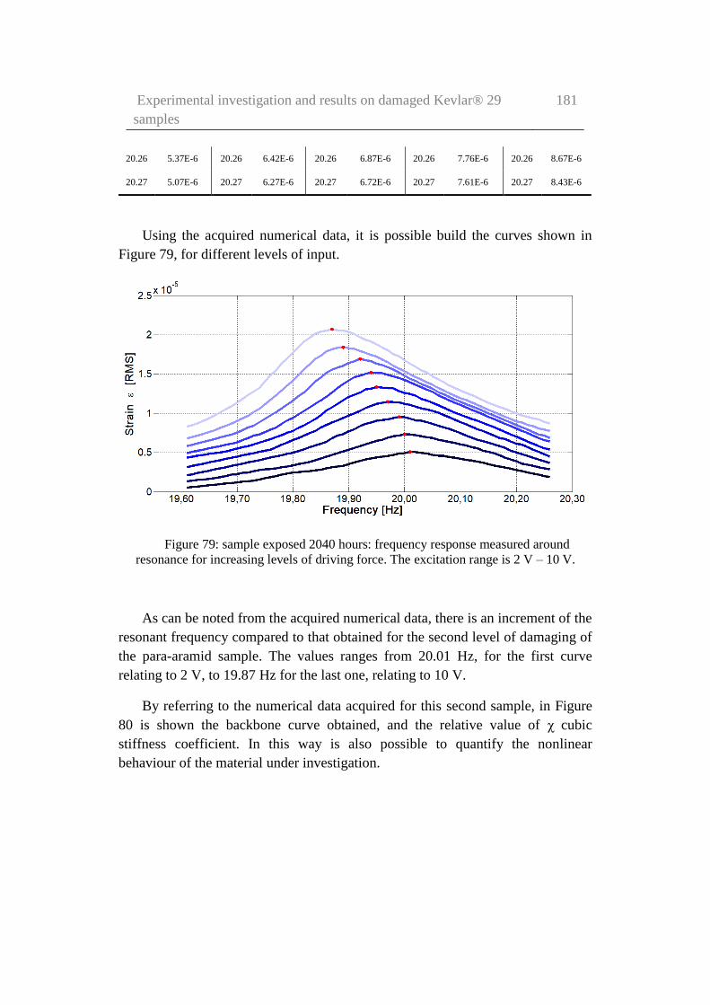
Experimental investigation and results on damaged Kevlar® 29
samples
181
20.26 5.37E-6 20.26 6.42E-6 20.26 6.87E-6 20.26 7.76E-6 20.26 8.67E-6
20.27 5.07E-6 20.27 6.27E-6 20.27 6.72E-6 20.27 7.61E-6 20.27 8.43E-6
Using the acquired numerical data, it is possible build the curves shown in
Figure 79, for different levels of input.
Figure 79: sample exposed 2040 hours: frequency response measured around
resonance for increasing levels of driving force. The excitation range is 2 V – 10 V.
As can be noted from the acquired numerical data, there is an increment of the
resonant frequency compared to that obtained for the second level of damaging of
the para-aramid sample. The values ranges from 20.01 Hz, for the first curve
relating to 2 V, to 19.87 Hz for the last one, relating to 10 V.
By referring to the numerical data acquired for this second sample, in Figure
80 is shown the backbone curve obtained, and the relative value of χ cubic
stiffness coefficient. In this way is also possible to quantify the nonlinear
behaviour of the material under investigation.

182 Elena Pinotti – Dynamic characterization of high-performance
materials for application to cultural heritage
Figure 80: sample exposed 2040 hours: frequency response measured around
resonance for increasing levels of driving force. The excitation range is 2 V – 10 V. The
red dots highlight the maximum of the response curve and the dashed red line is the
estimated backbone response curve.
The cubic stiffness coefficient obtained in this case is equal to 𝜒 = −7.221 ∙
1011 𝑁 𝑚3⁄ .
Finally, the value of the ζ damping of the system was calculated applying the
half-power bandwidth method, and was computed for the 5 V response and was
estimated at 0.69% (Q= 73).
Alternatevely, the resonant frequency distortion can be quantified by the
nonlinear backbone curve connecting peak amplitudes ap of the various resonance
curves at different excitation levels. The frequency f(ap) at which the peak occurs
can be approximated using perturbation analysis (Worden & Tomlinson, 2001) as
𝑓(𝑎𝑝) = 𝑓0√1 +3
4
𝑘3
𝑘𝑎𝑝
2
(25)
where f0 is the frequency of the underlying resonance frequency.

Experimental investigation and results on damaged Kevlar® 29
samples
183
In order to identify a material-specific device-independent parameter, the
backbone curves represented here in terms of the deformation strain ε, with a
dimensionless coefficient:
𝑋 =3
4𝐿2𝑘3𝑘
(26)
where k3 in the cubic stiffness coefficient, k the linear stiffness term, and L the
sample length.
The non-linearity index rewritten in this way is dimensionless and suitable to
characterize material non-linearity. Its rms value, indicated just as ε, will be used
for consistency. Equation 25 is then rewritten as
𝑓(𝑎𝑝) = 𝑓0(1 + 𝑋𝜀2)
(27)
The common engineering unit µε will be adopted, usually indicated as
“micro-strain” (1 µε =1 µm/m). Equation 27 was used to identify X from the
backbone curve.
The coefficient X of Equation 27 was estimated for each sample by fitting the
theoretical parabolic shape of the backbone curve onto the family of resonance
curves. The dots mark the peaks of response curves and the dashed red line is the
best estimated backbone curve. The coefficient X was obtained by peak
frequencies and peak strains of various pairs of curves in Equation 28, and
combining results in an uncertainty weighted average.
𝑓1 − 𝑓2
𝑓2= 𝑋(𝜀1
2 − 𝜀22) (28)
In Equation 28, indexes 1 and 2 identify parameters of the two curves of the
pair used in the calculation. Absolute uncertainty was evaluated for X to be less
than 1∙10-6 for all families of curves by computing the standards deviation of such
values and dividing it by the square root of the used number of pairs. This means
for the most damaged sample a relative uncertainty of roughly 5%, aligned to
what evaluated for the other quantities. However, in this case, it turns out to be
more than adequate to support clear evidence of the effects of UV exposure
because X was increased in the process by almost a factor of four.

184 Elena Pinotti – Dynamic characterization of high-performance
materials for application to cultural heritage
The best values obtained for the coefficient X are -5.6∙10-6, -1.08∙10-5, -
1.41∙10-5, and -1.81∙10-5 per square micro strain respectively for 0, 792, 1272, and
2040 hours of exposure to UV radiation.
The progressive increase in non-linearity is represented in Figure 81, where a
linear increase of the coefficient X versus exposure time can be clearly observed.
Figure 81: variations of measured nonlinear coefficient X with respect to UV
exposure time.
The slope of the non-linearity coefficient change versus exposition to UVA
radiation time in hours can be evaluated from this plot to be about -6.1∙10-9/h at
the used irradiation level of 1 kW/m2. This is equivalent to about -0.3∙10-9/J of
incident UV energy on 1 m of a single 12 µm fibre, according to the dose
evaluation given in section 6.2. Whether the damage per Joule depends on
radiation level remains to be determined. What can be safely stated here is that
unambiguous detection of UV damage can be assessed with this method at the
present level of uncertainty after about 150 h of continuous exposure to 1 kW/m2
UVA radiation, because that is the time that it takes in these conditions for X to
increase more than the uncertainty. This is equivalent to about 2 years of normal
environmental UV exposure at mid latitudes if damage is independent of intensity.
The question whether this is true deserves more experimentation.
How changes in the nonlinear coefficient are physically related with fibre
deterioration, and whether reduced fibre strength can be reliably evaluated by
measurements of non-linearity with the low excitation method illustrate here, are

Experimental investigation and results on damaged Kevlar® 29
samples
185
questions that most certainly deserve further attention, but the possibility of
developing this approach into a field applicable non-destructive method appears
unquestionably attractive.
6.2.4 Comparison of the results obtained
Tests were carried out on different Kevlar® 29 yarn samples extracted from
the same bundle. Yarns consist of roughly 1500 fibres, 12 μm in diameter, judging
from the specified 2500 dTex number provided by the manufacturer, which yields
a total cross-sectional area of 0.174 mm² for the bundle. This value is used to
convert voice coil force into applied stress, for which a maximum rms value of
about 20 kPa is obtained. Four samples were cut to equal length, for a free length
in operation in the test machine of 665 mm. Uncertainty on the latter was
estimated to be about ±1 mm. One of the samples was not exposed to UV and
served as a reference. The other three were exposed to radiation as detailed in this
chapter. The yarn is pale yellow when new, but takes on an increasingly “burnt”
colour after exposure to UV radiation.
The resonance frequency of about 20 Hz of all samples returns a tensile
modulus of 70 GPa by using the mentioned values for length and cross section,
quite in line with typical data which can be found in the literature. Sample-to-
sample variations are below 5% and must be considered meaningless due to lack
of information on actual fibre count and diameter.
The damping coefficient ζ (estimated with the half-power bandwidth method)
appeared to vary for all samples with the excitation level, increasing from below
0.005 (Q above 100) at the 4 kPa rms (2 V), to below 0.006 (Q above 80) at the 20
kPa rms (10 V). However, for low excitation, values obtained with this approach
are quite strongly affected by the judgement on where the zero is positioned in the
curve, and for high-excitation by detector saturation.
Uncertainty must therefore be taken conservatively to be at least of the order
of a few percent, and higher at low excitation. A correction can be applied to
account for detector non-linearity, which seems to suggest smaller dependence of
damping on excitation level than is shown in Figure 82. This is not reported here
as quality factor at the end didn’t turn out to change significantly with UV
exposure and was finally discarded as a useful indicator for UV damage in para-
aramid fibres.

186 Elena Pinotti – Dynamic characterization of high-performance
materials for application to cultural heritage
Figure 82: measured variations of Q-factor versus drive level for different exposure
times to UV.
In Figure 82 variations with excitation level of measured quality factor Q are
shown for all four samples. It can be noticed that the curves show similar
magnitude and behaviour. Because of the uncertainty in the Q factor
determination, the slight decrease in the Q values that might be inferred by these
curves does not appear to be significant.
It may be useful to point out here that the peak tension developed on
resonance in the sample for the maximum excitation stress of 20 kPa rms (10 V),
as obtained by multiplying it by the Q factor, can be inferred to be about 2.2 MPa.
This is less than 3% of the preloading given by the weight of the oscillating mass
at rest (which guarantees the sample is never fully unloaded), and less than 0.1%
of the ultimate strength of the material (which proves the ability of the adopted
approach to monitor damage without overstressing the sample).
In Table 17, are contained the results of the forced tests obtained in terms of
frequency, non-linearity index, and quality factor (for the 5 V response), both for
the case of original Kevlar® sample, that for the three level of damaging.
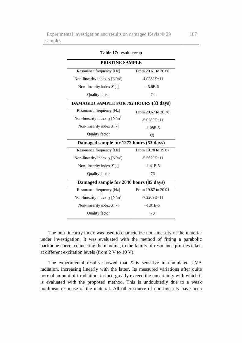
Experimental investigation and results on damaged Kevlar® 29
samples
187
Table 17: results recap
PRISTINE SAMPLE
Resonance frequency [Hz] From 20.61 to 20.66
Non-linearity index χ [N/m3] -4.0282E+11
Non-linearity index X [-] -5.6E-6
Quality factor 74
DAMAGED SAMPLE FOR 792 HOURS (33 days)
Resonance frequency [Hz] From 20.67 to 20.76
Non-linearity index χ [N/m3] -5.0280E+11
Non-linearity index X [-] -1.08E-5
Quality factor 86
Damaged sample for 1272 hours (53 days)
Resonance frequency [Hz] From 19.78 to 19.87
Non-linearity index χ [N/m3] -5.5670E+11
Non-linearity index X [-] -1.41E-5
Quality factor 76
Damaged sample for 2040 hours (85 days)
Resonance frequency [Hz] From 19.87 to 20.01
Non-linearity index χ [N/m3] -7.2209E+11
Non-linearity index X [-] -1.81E-5
Quality factor 73
The non-linearity index was used to characterize non-linearity of the material
under investigation. It was evaluated with the method of fitting a parabolic
backbone curve, connecting the maxima, to the family of resonance profiles taken
at different excitation levels (from 2 V to 10 V).
The experimental results showed that X is sensitive to cumulated UVA
radiation, increasing linearly with the latter. Its measured variations after quite
normal amount of irradiation, in fact, greatly exceed the uncertainty with which it
is evaluated with the proposed method. This is undoubtedly due to a weak
nonlinear response of the material. All other source of non-linearity have been

188 Elena Pinotti – Dynamic characterization of high-performance
materials for application to cultural heritage
duly considered, modelled and quantified as negligible in Chapter 4. Using this
parameter to assess cumulated damage occurred in Kevlar® 29 fibres from
exposure to environmental UVA radiation should therefore be considered
seriously.
The other characteristics considered do not show the same clear and easily
identified sensitivity, and should therefore be discarded as damage detectors.
Specifically, the tensile modulus does not seem to suffer noticeably from UV
irradiation, although the increasing non-linearity suggests a possible decrease in
ultimate strength. How exactly the two may be physically related to radiation
appears to deserve further study at the light of results presented here.
Therefore, this result is confirming our initial hypothesis that this parameter
may be used as a valuable and trustworthy index of damage in case of material
evaluation, for applications in Structural Health Monitoring (SHM) field. With the
uncertainty level demonstrated in this work, a couple of years of deployment in
normal outdoors would already show a measurable increase in non-linearity,
which would imply a decrease in ultimate strength. Clearly, more sensitive
methods might be devised, allowing even earlier warning of UV damage.

Experimental investigation and results on damaged Kevlar® 29
samples
189
190 Elena Pinotti – Dynamic characterization of high-performance
materials for application to cultural heritage
Chapter 7
A new concept for a tie element
with self-diagnosis properties
As stated in the introductive sections, this research was developed in the field
of “Advanced Structural Materials for Applications to Cultural Heritage”. In
particular, this work is focused on high-performance materials for applications
aimed to structural and seismic protection of cultural heritage. For this reason, the
final aim of the whole research was to define a self-diagnosis strategy for high-
strength fibres, yarns and ties in view of efficient, non-invasive, and reversible
interventions on cultural heritage buildings.
The work reported in the previous chapters has demonstrated a link between
the exposure time to UV rays, and the dynamic behaviour of the material. This
connection was evaluated by means of a non-linearity index. Exposure to UV rays
was used to produce a damage because aramid materials, such as Kevlar®, are
particularly sensitive to this factor. The prototype testing machine developed in
this research (see chapter 4) has been conceived in order to be able to detect weak
nonlinear behaviours, being consequently a very sensitive machine.
It was decided to use the distinctive characteristics of the testing machine to
create a control system with self-diagnosis properties for applications to in-place
reinforcement elements, which are in need of continuous (on line) monitoring. A
natural application of this testing strategy could be on ties realised with HPM

A new concept for a tie element with self-diagnosis properties 191
materials, ad those employed for the reinforcement of structural elements of
building with particular historical and artistic relevance.
In this chapter, which constitutes the conclusive part of this work, a new
concept of control system with self-diagnosis properties was described. This may
result in possible applications of our prototype-testing machine to structural and
seismic protection of cultural heritage, i.e. the final aim of this dissertation.
7.1 Structural Health Monitoring
Figure 83: typical Structural Health Monitoring strategy..
According to Worden (Farrar & Worden, 2013), the damage will be defined
as changes to the material and/or geometric properties of a structural or
mechanical system, including changes to the boundary conditions and system
connectivity, which adversely affect current or future performance of that system
(Figure 83).

192 Elena Pinotti – Dynamic characterization of high-performance
materials for application to cultural heritage
Implicit in this definition of damage is a comparison between two different
states of the system (i.e. stiffness, boundary and/or connectivity change).
All materials used in engineering systems have some inherent initial flaws.
Under appropriate loading flaws will grow and coalesce to the point where they
produce component level failure. Further loading may cause additional component
failures that can lead to system-level failure. In some cases this evolution can
occur over relatively long time scales (e.g. corrosion, fatigue crack growth).
Instead, other cases cause this damage evolution to occur over relatively short
time scales (e.g. earthquake loading, impact-related damage).
Must consider the length and time scales associated with damage initiation
and evolution when developing a SHM system. SHM is the process of
implementing a damage detection strategy for different field of application such
as aerospace, civil and mechanical engineering infrastructure. This technique is
very useful for “novel materials”, because the long-term degradation processes are
not well understood.
The SHM process involves the observation of a system over time using
periodically sampled dynamic response measurements from an array of sensors.
The extraction of damage-sensitive features from these measurements. The
statistical analysis of these features is then used to determine the current state of
system health. SHM can make use of non-destructive evaluation techniques.
After extreme events, such as earthquakes or blast loading, SHM is used for
rapid condition screening and aims to provide, in near real time, reliable
information regarding the integrity of the structure (Farrar & Worden, 2013).
7.2 The concept of a tie with self-diagnosis properties
There is a growing body of literature on non-destructive evaluation technique.
The low cost system proposed in this work, could be realised by using the same
components, devices, and principle of operation described in Chapter 4. The
interesting aspect is that the testing machine developed is less invasive, very
versatile (could be adapted to different situation), cheap, and, and removable with
little effort.
The setup may be modified case-by-case, taking into account:
the special needs,
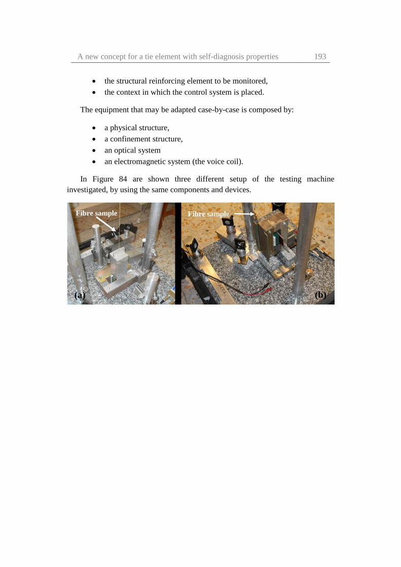
A new concept for a tie element with self-diagnosis properties 193
the structural reinforcing element to be monitored,
the context in which the control system is placed.
The equipment that may be adapted case-by-case is composed by:
a physical structure,
a confinement structure,
an optical system
an electromagnetic system (the voice coil).
In Figure 84 are shown three different setup of the testing machine
investigated, by using the same components and devices.
(a) (b)
Fibre sample Fibre sample

194 Elena Pinotti – Dynamic characterization of high-performance
materials for application to cultural heritage
Figure 84: possible setup configurations investigated: a) vertical sample, and
suspended mass of 1.345 kg, b) horizontal sample, and mass of 0.150 kg, c) vertical
sample, and suspended mass of 45 kg.
In the following Figures 85-87 a possible alternative solution is shown of how
this testing machine could be applied to ties employed for the reinforcement of
masonry arches and vaults, as a system with self-diagnosis properties.
In the setup of the testing machine used in Chapters 5 and 6, the sample
investigated was placed vertically with a suspended mass at one hand, which
guaranteed the tensioned during the tests (Figure 85 a-b). A small ball lens was
glued on a support attached to the suspended mass, through which it was possible
an indirect reading of the sample displacement. In this new setup, the ball lens is
applied to a mass placed in a middle span (Figure 85 c).
(c)
Fibre sample

A new concept for a tie element with self-diagnosis properties 195
Figure 85: different setup investigated with different ball lens position.
The system shown in these figures is nothing more than an example of one
possible application, not in scale. It was built in the Metrology Laboratory of the
Electronic and Telecommunication Department of Politecnico di Torino.
(c)
(b) (a)
(c)

196 Elena Pinotti – Dynamic characterization of high-performance
materials for application to cultural heritage
Figure 86: the concept of control and self-diagnosis system.
In this case, since it is applied to an existing reinforcing element, which is
already tensioned, as in the case of a tie for example, the mass is positioned at
mid-span, and does not apply a stress into the element. In any case, the measured
displacement of the mass allows the study of the dynamic behaviour of the
element under investigation.
Figure 87: the concept of the system for self-diagnosis: demonstrative sketch of a
possible application.
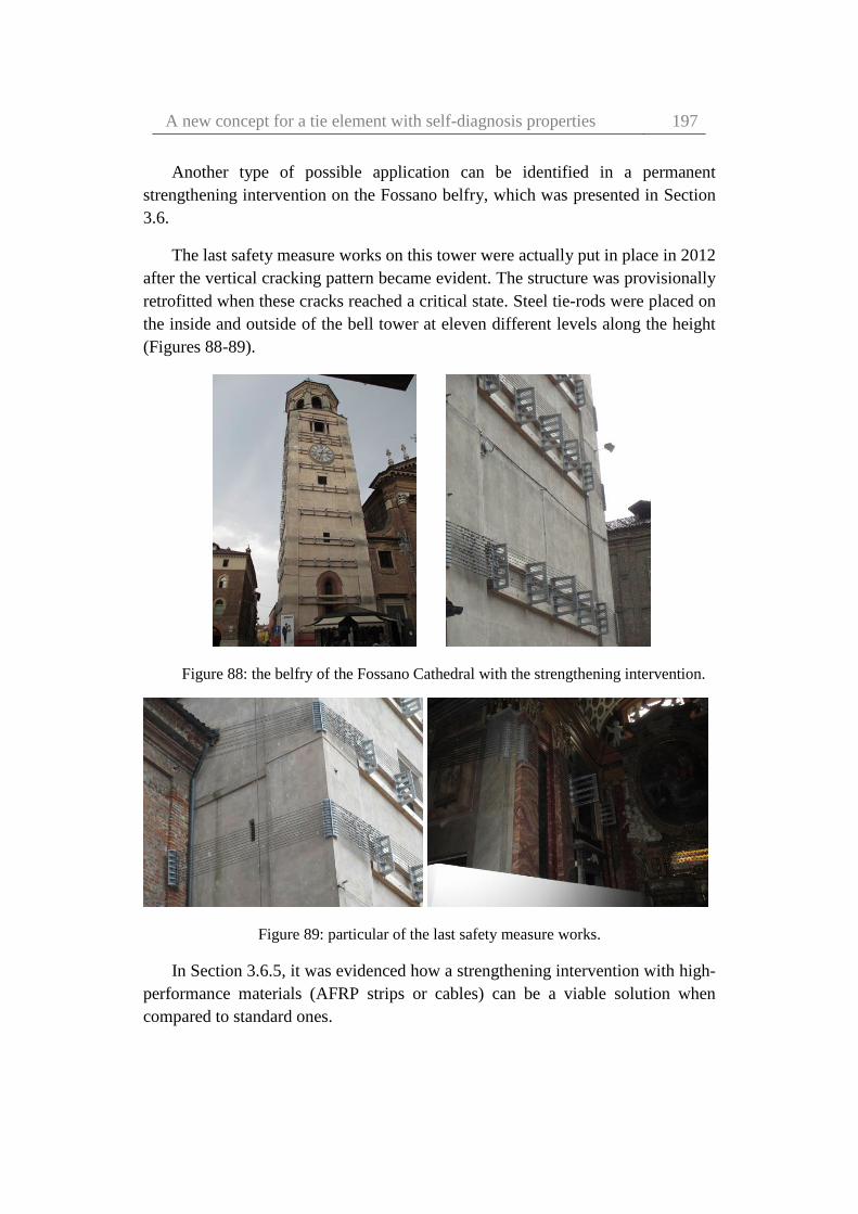
A new concept for a tie element with self-diagnosis properties 197
Another type of possible application can be identified in a permanent
strengthening intervention on the Fossano belfry, which was presented in Section
3.6.
The last safety measure works on this tower were actually put in place in 2012
after the vertical cracking pattern became evident. The structure was provisionally
retrofitted when these cracks reached a critical state. Steel tie-rods were placed on
the inside and outside of the bell tower at eleven different levels along the height
(Figures 88-89).
Figure 88: the belfry of the Fossano Cathedral with the strengthening intervention.
Figure 89: particular of the last safety measure works.
In Section 3.6.5, it was evidenced how a strengthening intervention with high-
performance materials (AFRP strips or cables) can be a viable solution when
compared to standard ones.

198 Elena Pinotti – Dynamic characterization of high-performance
materials for application to cultural heritage
The proposed self-diagnosis system can be incorporated in cables made with
high-performance materials (e.g. Kevlar®), which are placed inside or outside the
belfry (in protected positions). This system can detect changes in the material
properties which affect the dynamic properties of the structure, this representing
an advantegeous choice for provisional and/or reversible interventions. In fact, the
minimally invasive self-diagnosis system presented in this chapter can constantly
monitor the efficacy of the system, e.g. due to the possible relaxation phenomena.
In conclusion, this last chapter strives for emphasize how, with accurate and
well-thought design, it is possible to realise a cheap control system, able to
measure dynamic parameters by using a relatively low-cost equipment. Currently,
the same measurements can be performed only in very controlled environments
and would require very costly equipment. With this new concept, after the
accomplishment of the full engineering process, it will be possible to conceive
self-diagnosis systems and interventions that satisfy all the mentioned principles
of conservation (see Chapter 1), with a view to producing real world applications
to cultural heritage buildings.

A new concept for a tie element with self-diagnosis properties 199

200 Elena Pinotti – Dynamic characterization of high-performance
materials for application to cultural heritage
Conclusions
This dissertation concerns high resistance materials for application to seismic
protection and monitoring of cultural heritage, with a special focus on historical
masonry structures. In particular, the final aim of this research was to define a
self-diagnosis strategy for fibres, yarns and ties in view of efficient, non-invasive,
reversible and cheap intervention on cultural heritage buildings.
The first part of the this work illustrates the principles and realization of a
prototype apparatus for fiber testing, capable of accurately measuring material Q
values up to 103. The presented results were obtained from three different types of
high strength fibers, namely Kevlar® 29, Silicon Carbide and Carbon.
Suggestions are also given for the improvement of the apparatus and for extending
its accuracy. The proposed apparatus could be a critical tool in the study of
mechanical dissipation mechanisms in materials with particularly low levels of
intrinsic dissipation.
As a further step, it was explored the potential of a recently conceived optical
test system for high-sensitivity dynamic measurements, for assessing damage
caused by UV exposure of Kevlar® 29 samples. Various mechanical properties of
the fibres were estimated and compared at different damage levels. The non-
linearity index, identified resorting to the backbone curve, proved to be a more
robust damage indicator with respect to damping.
The experimental findings led to propose a concept in which a prototype acts
as a control system with self-diagnosis properties for fibres, yarns and ties. The
proposed application of the new prototype-testing machine is precisely in the field
of structural and seismic protection of cultural heritage. In addition, the
dissertation emphasized how, with accurate and well-thought design, it is possible
to measure these dynamic parameters using a relatively low-cost equipment,

A new concept for a tie element with self-diagnosis properties 201
compared to typical costs of dynamic testing machines. In the field of cultural
heritage, in particular, the availability of low-cost sensing and actuation devices
will be a key factor for conceiving non-invasive and reversible interventions with
high resistance materials.
Future studies will investigate different definitions for the non-linearity index
to be used for diagnosis purpose.
In addition, the prototype testing machine will be optimised for application to
full-scale heritage structures. Further verifications on HPM are necessary,
especially about their performances when are coupled with masonry and other
traditional materials. Further research will be in turn required to develop and
incorporate a control strategy, so as to exploit the self-diagnosis properties and
transform the concept to reality.

202 Elena Pinotti – Dynamic characterization of high-performance
materials for application to cultural heritage
References
(FIB), F. I. d. B., 2001. Externally bonded FRP reinforcement for RC
structures. Lausanne, Switzerland: Bulletin 14.
ACI Committee 440, 2001. Guide for the design and construction of concrete
reinforced with FRP bars. Farmington Hills, Mich.: American Concrete Institute.
ACI Committee 440, 1996. State of the art report on fiber reinforced plastic
(FRP) reinforcement for concrete structures. Farmington Hills, Mich.: American
Concrete Institute.
Adams, D. & Allemang, R., 1999. A new derivation of the frequency
response function matrix for vibrating non-linear systems. Journal of Sound and
Vibration, 227(5), pp. 1083-1108.
Aiello, M. & Conte, C., 2009. Seismic vulnerability of masonry curved
elements. Venezia, Associazione Italiana Compositi (AICO), pp. 1-8.
Aiello, M., Micelli, F. & Valente, L., 2005. Circular masonry columns
confined with FRP. Lyon, France, Proceedings of the 3rd International
Conference.
Aiello, M., Micelli, F. & Valente, L., 2007. Structural Upgrading of Masonry
Columns by Using Composite Reinforcements. Journal of Composites for
Construction, pp. 650-658.
Aiello, M. & Sciolti, M., 2009. Elementi curvi in muratura rinforzati con
nastri in FRP: analisi dell'aderenza. Venezia, Associazione Italiana Compositi
(AICO), pp. 18-25.
References 203
Aiello, M. & Sciolti, S., 2006. Bond analysis of masonry structures
strengthened with CFRP sheets. Construction and Building Materials, pp. 90–
100.
Alecci, V., Briccoli Bati, S. & G., R., 2009. Confining compressed pillars
with FRP composites. Venezia, Associazione Italiana Compositi (AICO), pp. 26-
33.
Alecci, V., Briccoli Bati, S. & Ranocchiai, G., 2009. Confining compressed
pillars with FRP composites. Venezia, Aocciazione Italiana Compositi (AICO),
pp. 26-33.
Allard, J. & Champoux, Y., 1992. New empirical equations for sound
propagation in rigid frame fibrous materials. The Journal of Acoustical Society of
America, pp. 3346-3353.
Amada, S. et al., 1997. The mechanical structures of bamboos in viewpoint of
functionally gradient and composite materials. Journal of Composite Materials,
pp. 800–819.
Arrieta, C., David, E., Dolez, P. & Vu-Khanh, T., 2011. Hydrolytic and
photochemical aging studies of a Kevlar-PBI blend. Polymer Degradation and
Stability, pp. 1411-1419.
Ascione, L., Feo, L. & Fraternali, F., 2005. Load carrying capacity of 2D
FRP/strengthened masonry structures. Composites Part B, pp. 619–626.
Ascione, L., Napoli, A. & Realfonzo, R., 2009. Strengthening of masonry
with Mechanically Fastened FRP laminates. Venezia, Associazione Italiana
Compositi (AICO), pp. 43-50.
Bakis, C. et al., 2002. Fiber-Reinforced Polymer Composites for
Construction: State-of-the-Art Review. Journal of composites for construction,
pp. 73-83.
Baratta, A. & Corbi, O., 2007. Stress analysis of masonry vaults and static
efficacy of FRP repairs. International Journal of Solids and Structures, pp. 8028–
8056.
Barbieri, A., Borri, A., Corradi, M. & Di Tommaso, A., 2002. Dynamic
Behaviour of Masonry Vaults Repaired with FRP: Experimental Analysis.

204 Elena Pinotti – Dynamic characterization of high-performance
materials for application to cultural heritage
Basilio, I., Oliveira, D. & Lourenço, P., 2004. Optimal FRP strengthening of
masonry arches. Amsterdam, pp. 1-10.
Beckmann, P. & Bowles, R., 2004. Structural aspects of building
conservation. Oxford Elsevier.
Bednarz, L., Jasienko, J., Rutkowski, M. & Nowak, T., 2014. Strengthening
and long-term monitoring of the structure of an historical church presbytery.
Engineering Structures, pp. 62-75.
Benichou, N., Kodur, V., Green, M. & Bisby, L., 2010. Fire Performance of
Fibre-Reinforced Polymer Systems Used for the Repair of Concrete Buildings.
Construction Technology Updates - CNRC, pp. 1-6.
Berg, A., Bank, L., Oliva, M. & Russell, J., 2006. Construction and cost
analysis of an FRP reinforced concrete bridge deck. Construction and Building
Materials, pp. 515–526.
Bertha, M. & Golinval, J., 2014. Identification of a time-varying beam using
Hilbert Vibration Decomposition. Orlando, FL, USA.
Berthelot, J. & Sefrani, Y., 2004. Damping analysis of unidirectional glass
and Kevlar fibre composites. Composites Science and Technology, pp. 1261-1278.
Betti, M. & Vignoli, A., 2008. Modelling and analysis of a Romanesque
church under earthquake loading: Assessment of seismic resistance. Engineering
Structures, pp. 352-367.
Bin Kabir, R. & Ferdous, N., 2012. Kevlar-The Super Tough Fiber.
International Journal of Textile Science, pp. 78-83.
Boothby, T., 2003. Analysis of masonry arches and vaults. Progress in
Structural Engineering and Materials, pp. 246-256.
Borri, A., Casadei, P., Castori, G. & Ebaugh, S., 2007. Research on composite
strengthening of masonry arches. Patras, Greece, Proceedings of the 8th
International Symposium.
Borri, A., Casadei, P., Castori, G. & Hammond, J., 2009. Strengthening of
Brick Masonry Arches with Externally Bonded Steel Reinforced Composites.
Journal of Composites for Construction, pp. 468-475.
References 205
Borri, A. & Castori, G., 2009. Un contributo allo studio della durabilità dei
rinforzi strutturali con materiali compositi. Venezia, Associazione Italiana
Compositi (AICO), pp. 99-107.
Borri, A., Castori, G. & Corradi, M., 2009. Una nuova tecnica di
realizzazione di muratura armata con fibre metalliche. Venezia, Associazione
Italiana Compositi (AICO), pp. 108-115.
Borri, A., Castori, G. & Paci, G., 2009. Indagine numerica sull’efficacia
dell’utilizzo di nastri in materiali compositi fibrorinforzati applicati su volte
cilindriche. Venezia, Associazione Italiana Compositi (AICO), pp. 116-123.
Borri, A. & Corradi, M., 2009. Confinamento di pilastri in muratura tramite
compositi con fibre metalliche. Venezia, Associazione Italiana Compositi (AICO),
pp. 124-131.
Borri, A., Corradi, M. & Vignoli, A., 2002. New materials for strengthening
and seismic upgrading interventions. Prague, Czech Republic.
Boscato, G., Russo, S., Ceravolo, R. & Zanotti Fragonara, L., 2015. Global
Sensitivity-Based Model Updating for Heritage Structures. Computer-Aided Civil
and Infrastructure Engineering, pp. 620-635.
Botelho, E. et al., 2006. Damping behaviour of continuous fibre/metal
composite materials by the free vibration method. Composites: Part B, pp. 255-
263.
Branco, M. & Guerreiro, L., 2011. Seismic rehabilitation of historical
masonry buildings. Engineering Structures, pp. 1626-1634.
Braun, S. & Feldman, M., 2011. Decomposition of non-stationary signals into
varying time scales: Some aspects of the EMD and HVD methods. Mechanical
Systems and Signal Processing, pp. 2608-2630.
Briccoli Bati, S. & Rotunno, T., 2001. Environmental durabilily of the bond
between the CFRP composite materials and masonry structures.. Guimaraes,
Portugal,, Proceedings of the 3rd International Conference, pp. 1039–1046.
Briccoli Bati, S. & Rovero, L., 2000. Consolidation of masonry arches with
carbon-fiber reinforced plastics. Madrid, Spain.
206 Elena Pinotti – Dynamic characterization of high-performance
materials for application to cultural heritage
Briccoli Bati, S. & Rovero, L., 2001. Experimental validation of a proposed
numerical model for the FRP consolidation of masonry arches. Guimaraes,
Portugal, Proc. of the 3rd Int. Conf., pp. 1057–1066.
Briccoli Bati, S. & Rovero, L., 2008. Towards a methodology for estimating
strength and collapse mechanism in masonry arches strengthened with fibre
reinforced polymer applied on external surfaces. Materials and Structures, pp.
1291–1306.
Briccoli Bati, S. & Rovero, L., 2009. Experimental analysis on scale models
of CFRP reinforced arches. Venezia, Associazione Italiana Compositi (AICO),
pp. 140-145.
Buchan, P. & Chen, J., 2007. Blast resistance of FRP composites and polymer
strengthened concrete and masonry structures– A state-of-the-art review.
Composites: Part B, pp. 509-522.
Bunton, D., 2002. Generic moves in PhD thesis introductions.. In: Academic
discourse. London: Pearson Education Limited, pp. 57-75.
Burgoyne, C., 1987. Structural use of parafil ropes. Construction & Buildings
materials, pp. 3-13.
Burgoyne, C., 1993. Parafil ropes for prestressing applications. Fibre-
Reinforced-Plastic Concr. Struct. Prop. Appl., pp. 333–351.
Burgoyne, C., 1998. Advanced composites - the challenge to bridge designers.
Calgary, Alberta, Canada, Canadian Society for Civil Engineering, pp. 1-14.
Burgoyne, C. & Balafas, I., 2007. Why is FRP not a financial success?.
Patras, Greece, pp. 7-18.
Burgoyne, C. J., 1991. Parafil ropes - from development to application.
Cambridge.
Burley, E. & Rigden, S. R., 1997. The use of life cycle costing in assessing
alternative bridge design. London, Municipal Engr., pp. 22-27.
Cai, G., Li, D., Fang, D. & Yu, W., 2014. A new apparatus to measure the
effect of temperature and light on the bending fatigue properties of Kevlar 49 and
PBO fibers. Polymer Testing, pp. 143-148.

References 207
Calderoni, B., Cordasco, E., Lenza, P. & Pacella, G., 2009. Indagine
sperimentale su elementi compressi in muratura di tufo rinforzati con fibre di
carbonio. Venezia, Associazione Italiana Composito (AICO), pp. 153-160.
Campbell, F., 2010. Structural Composite Materials. Materials Park, OHIO:
ASM International.
Capozucca, R. & Ricci, V., 2016. Bond of GFRP strips on modern and
historic brickwork masonry. Composite Structures, pp. 540-555.
Caprili, S., Mangini, F. & Salvatore, W., 2015. Evaluation of structural safety
and seismic vulnerability of historic studies and applications. WIT Press, pp. 369-
380.
Caratelli, A., Ianniruberto, U. & Rinaldi, Z., 2009. Experimental behaviour of
masonry frames strengthened with composite sheets. Venezia, Associazione
Italiana Compositi (AICO), pp. 161-168.
Cardoso, R., Lopes, M. & Bento, R., 2005. Seismic evaluation of old masonry
buildings. Part I: Method description and application to a case-study. Engineering
Structures, pp. 2024–2035.
Carrella, A. & Ewins, D., 2011. Identifying and quantifying structural
nonlinearities in engineering applications from measured frequency response
functions. Mechanical Systems and Signal Processing, 25(3), pp. 1011-1027.
Casareto, M., Oliveri, A., Romelli, A. & Lagomarsino, S., 2003. Bond
behavior of FRP laminates adhered to masonry. Milano, Italy, Proceedings of the
International Conference.
Cavalagli, N. & Gusella, V., 2015. Dome of the Basilica of Santa Maria Degli
Angeli in Assisi: Static and Dynamic Assessment. International Journal of
Architectural Heritage, pp. 157-175.
Cecchi, A., Milani, G. & Tralli, A., 2004. In-plane loaded CFRP reinforced
masonry walls: mechanical characteristics by homogenisation procedures.
Composites Science and Technology, pp. 2097–2112.
Celestini, G., 2009. Evoluzione della tecnologia dei rinforzi strutturali con
materiali composite nel consolidamento e recupero del patrimonio monumentale
e di edifici esistenti attraverso l’analisi di esperienzeumbre. Ipotesi di sviluppo.
Venezia, Associazione Italiana Compositi (AICO), pp. 177-183.

208 Elena Pinotti – Dynamic characterization of high-performance
materials for application to cultural heritage
Celestini, G., 2009. Innovation on Advanced Composite Materials for
Strengthening and Protection of Historical Masonry Structures. Venezia,
Associazione Italiana Compositi (AICO), pp. 184-191.
Ceravolo, R. et al., 2012. Reconciling geometry and dynamics: model for oval
domes. Firenze
Ceravolo, R. et al., 2017. A New Testing Machine for the Dynamic
Characterization of High Strength Low Damping Fiber Materials. Experimental
Mechanics, pp. 65–74.
Ceravolo, R. et al., 2018. Measurement of weak non-linear response of
Kevlar® fibre damaged by UV exposure. Composite Structures, pp. 807-813.
Ceravolo, R., Erlicher, S. & Zanotti Fragonara, L., 2013. Comparison of
restoring force models for the identification of structures with hysteresis and
degradation. Journal of Sound and Vibration, pp. 6982-6999.
Ceravolo, R. et al., 2014. Vibration-based monitoring and diagnosis of
cultural heritage: a methodological discussion in three examples.. International
Journal of Architectural Heritage , pp. 274-303.
Černý, M., Glogar, P. & Manocha, L., 2000. Resonant frequency study of
tensile and shear elasticity moduli of carbon fibre reinforced composites (CFRC).
Carbon, pp. 2139-2149.
Chand, S., 2000. Review Carbon fibers for composites. Journal of Materials
Science, pp. 1303 – 1313.
Charter of Venice., 1964. Decision and Resolution. Venezia, pp. 25–31.
Chen, Q., Worden, K., Peng, P. & Leung, A., 2007. Genetic algorithm with an
improved fitness function for (N)ARX modelling. Mechanical Systems and Signal
Processing, pp. 994-1007.
Chopra, A., 1995. Dynamics of structures. Englewood Cliffs, New Jersey:
Prentice Hall.
Chou, T., Kelly, A. & Okura, A., 1985. Fibre-reinforced metal matrix
composites. Composites.
References 209
Christensen, B., Gilstrap, J. & Dolan, C., 1996. Composites Materials
Reinforcement of Exixsting Masonry Walls. Journal of Architectural
Engineering, pp. 63-70.
Circolare n°564., 1997. Istruzioni generali per la redazione dei progetti di
restauro nei beni architettonici di valore storico-artistico in zona sismica.
CNR-DT 200/2004, 2004. Istruzioni per la Progettazione, l’Esecuzione ed il
Controllo di Interventi di Consolidamento Statico mediante l’utilizzo di
Compositi Fibrorinforzati. pp. 1-172.
Codice dei Beni Culturali e del Paesaggio, 2004. Governo Italiano. Gazzetta
Ufficiale, 45. Governo Italiano.
Codispoti, R. et al., 2015. Mechanical performance of natural fiber-reinforced
composites for the strengthening of masonry. Composites Part B, pp. 74-83.
CompositeBuild.com, 2014. CompositeBuild.com. [Online]
Available at: http://compositebuild.com/inform/why-use-composites/
Composites, R., 2014. Revolution Composites. [Online]
Available at: http://www.revolutioncomposites.com/
Consiglio superiore dei lavori pubblici, 2011. Linee Guida per la valutazione
e riduzione del rischio sismico del patrimonio culturale - allineamento alle nuove
Norme tecniche per le costruzioni.
Corradi, M., Borri, A., Osofero, A. & Castori, G., 2015. Strengthening of
Historic Masonry Structures with Composite Materials. In: Handbook of Research
on Seismic Assessment and Rehabilitation of Historic Structures. Hershey (PA),
USA: IGI Global, pp. 257-292.
Corradi, M., Borri, A. & Vignoli, A., 2002. Strengthening techniques tested
on masonry structures struck by the Umbria-Marche earthquake of 1997–1998..
Construction and Building Materials, pp. 229-239.
Corradi, M., Grazini, A. & Borri, A., 2007. Confinement of brick masonry
columns with CFRP materials. Composites Science and Technology, p. 1772–
1783.
Corradi, M., Speranzini, E., Borri, A. & Vignoli, A., 2006. In-plane shear
reinforcement of wood beam floors with FRP. Composites: Part B, pp. 310-319.

210 Elena Pinotti – Dynamic characterization of high-performance
materials for application to cultural heritage
Corradi, S. et al., 2009. Composite Boat Hulls with Bamboo Natural Fibres.
International Journal Materials and Product Technology, pp. 73-89.
Council®, A. C., 2012-2017. Operation Clean Sweep®. [Online]
Available at: https://opcleansweep.org/Overview/About-SPI.html
Crane, R. & Gillespie, J., 1991. Characterization of the vibration damping loss
factor of glass and graphite fiber composites. Composite Science Technology, pp.
355-375.
Credali, L., 2002. Recupero strutturale di opere murarie nel Complesso della
Basilica di S. Antonio–Padova e nel Complesso di Venaria Reale–Torino,
mediante rinforzi ibridi: fibra di carbonio–fibra aramidica. Ferrara, Associazione
Italiana Compositi (AICO), pp. 1-11.
Credali, L., 2009. L’impiego delle tecnologie FRP nel recupero strutturale di
Edifici Storici. Venezia, Associazione Italiana Compositi (AICO), pp. 208-223.
Croci, G., 2000. General methodology for the structural restoration of historic
buildings: the cases of the Tower of Pisa and the Basilica of Assisi. Journal of
Cultural Heritage, pp. 7-18.
Croci, G., Ayala, D., Asdia, P. & Palombini, F., 1987. Analysis on shear walls
reinforced with fibres. Tokyo, Japan.
D’Ambra, C. et al., 2009. Confinement of tuff and brick masonry columns
with FRP laminates. Venezia, Associazione Italiana Compositi (AICO), pp. 232-
241.
Dahl, M., Rice, E. & Groesbeck, E., 1987. Effects of fiber motion on the
acoustic behaviour of an anisotropic, flexible fibrous material. Indianapolis,
Indiana.
Dark III, T., 2008. Reclaiming the Future: Space Advocacy and the idea of
progress. In: The Societal Impact of Spaceflight. Washington, DC: National
Aeronautics and Space Administration, pp. 555-572.
Das, S. & Nizam, E., 2014. Applications of Fibber Reinforced Polymer
Composites (FRP) in Civil Engineering. International Journal of Advanced
Structures and Geotechnical Engineering, pp. 299-309.

References 211
De Lorenzis, L., Dimitri, R. & La Tegola, A., 2007. Reduction of the lateral
thrust of masonry arches and vaults with FRP composites. Construction and
Building Materials, pp. 1415–1430.
De Lorenzis, L., Galati, N. & Ombres, L., 2004. In-plane shear strengthening
of natural masonry walls with NSM CFRP strips and FRCM overlay. Padova,
Italy, Proceedings of 4th International Sem., pp. 843–855.
De Lorenzis, L., Tinazzi, A. & Nanni, A., 2000. Near Surface Mounted FRP
Rods for Masonry Strengthening: Bond and Flexural Testing. Venezia, Italy, proc.
of the 2nd Nat. Symp.
Dell’Isola, A. J. & Kirk, S. J., 1981. Life cycle costing for design
professionals. New York: McGraw-Hill.
Demarie, G., Ceravolo, R., Sabia, D. & Argoul, P., 2010. Experimental
identification of beams with localized nonlinearities. Journal of Vibration and
Control.
Di Carlo, J. & Williams, W., 1980. Dynamic modulus and damping of boron,
silicon carbide and alumina fibers. Florida.
Dizhur, D., Griffith, M. & Ingham, J., 2014. Out-of-plane strengthening of
unreinforced masonry walls using near surface mounted fibre reinforced polymer
strips. Engineering Structures, pp. 330-343.
Dolan, C., 1990. Developments in Non-Metallic Prestressing Tendons.
Precast/Prestressed concrete institute, pp. 80-88.
Dresselhaus, M. et al., 1988. Graphite Fibers and Filaments. Berlino:
Springer-Verlag.
Du Pont, c., 2017. Du Pont. [Online]
Available at: http://www.dupont.com/products-and-services/fabrics-fibers-
nonwovens/fibers/articles/kevlar-properties.html
Duflou, J., Deng, Y., Van Acker, K. & Dewulf, W., 2012. Do fiber-reinforced
polymer composites provide environmentally benign alternatives? A life-cycle-
assessment-based study. MRS Bulletin, pp. 374-382.
Ehlen, M., 1997. Life-Cycle Costs of new construction materials. Journal of
Infrastructure systems, pp. 129-133.

212 Elena Pinotti – Dynamic characterization of high-performance
materials for application to cultural heritage
Ehlen, M., 1999. Life-Cycle Costs of fiber-reinforced-polymer bridge decks.
Journal of Materials in Civil Engineering, pp. 224-230.
Ehsani M.R., S. H. A.-S. A., 1997. Shear behavior of URM retrofitted with
FRP overlays.. Journal of Composites for Construction ASCE, pp. 17-25.
El Abdi, R. et al., 2008. New method for strength improvement of silica
optical fibres. Optics and Lasers in Engineering, pp. 222-229.
El-Dakhakhni, W., Hamid, A., Hakam, Z. & Elgaaly, M., 2006. Hazard
mitigation and strengthening of unreinforced masonry walls using composites.
Composite Structures, pp. 458–477.
ElGawady, M., Lestuzzi, P. & Badoux, M., 2005. In-Plane Seismic Response
of URM Walls Upgraded with FRP. Journal of Composites for Construction, pp.
524-535.
El-Mahdy, T. & Gadelrab, R., 2000. Free vibration of unidirectional fiber
reinforcement composite rotor. Journal of Sound and Vibration, pp. 195-202.
eurofibers, 2017. eurofibers, smart fiber solutions. [Online]
Available at: http://eurofibers.com/technora/
Ewins, D., 2000. Modal Testing: Theory, Practice and Application. Baldock,
UK: Research Studies Press.
Ewins, D., 2006. A future for experimental structural dynamics. Leuven,
Belgium.
Farrar, C. & Worden, K., 2013. Structural Health Monitoring- A machine
learning perspective. John Wiley & Sons, Ltd.
Feilden, B., 2003. Conservation of historic buildings. Architectural Press.
Feldman, M., 2006. Time-varying vibration decomposition and analysis based
on the Hilbert transform. Journal of Sound and Vibration, pp. 518-530.
Feldman, M., 2007. Considering high harmonics for identification of non-
linear systems by Hilbert transform. Mechanical Systems and Signal Processing,
pp. 943-958.
Feldman, M., 2007. Identification of weakly nonlinearities in multiple
coupled oscillators. Journal of Sound and Vibration, pp. 357-370.

References 213
Feldman, M., 2014. Hilbert transform methods for nonparametric
identification of nonlinear time varying vibration systems. Mechanical Systems
and Signal Processing, pp. 66-77.
Foraboschi, P., 2001. Strength Assessment of Masonry Arch Retrofitted
Using Composite Reinforcements. Masonry International, pp. 17-25.
Foraboschi, P., 2004. Strengthening of Masonry Arches with Fiber-
Reinforced Polymer Strips. Journal of Composites for Construction, pp. 191-202.
Forsyth, M. et al., 2007. Structures & construction in historic building
conservation. Blackwell Publishing Ltd.
Foster, P., Gergely, J., Young, D. & McGinley, M., 2005. Strengthening
masonry buildings with FRP composites. Edinburgh, UK., Proceedings of
International Conference.
Friston, K., Mechelli, A., Turner, R. & Price, C., 2000. Nonlinear Responses
in fMRI: The Balloon Model, Volterra Kernels, and Other Hemodynamics.
NeuroImage, pp. 466–477.
Fuellekrug, U. & Goege, D., 2012. Identification of weak non-linearities
within complex aerospace structures. Aerospace Science and Technology, 23(1),
pp. 53-62.
Garibaldi, L., 2003. Application of the conditioned reverse path method.
Mechanical Systems and Signal Processing, pp. 227–235.
Garmendia, L., San-José, J., García, D. & Larrinaga, P., 2011. Rehabilitation
of masonry arches with compatible advanced composite material. Construction
and Building Materials, pp. 4374–4385.
Gendelman, O., Starosvetsky, Y. & Feldman, M., 2008. Attractors of
harmonically forced linear oscillator with attached nonlinear energy sink I:
Description of response regimes. Nonlinear Dynamics, pp. 31-46.
Gibson, R. & Plunkett, R., 1977. A forced vibration technique for
measurement of material damping. Experimental Mechanics, pp. 297-302.
Gibson, R., Yau, A. & Riegner, D., 1982. An improved forced-vibration
technique for measurements of material damping. Experimental techniques, pp.
10-14.
214 Elena Pinotti – Dynamic characterization of high-performance
materials for application to cultural heritage
Gilstrap, J. & Dolan, C., 1998. Out-of-plane bending of FRP-reinforced
masonry walls.. Composites Science and Technology, pp. 1277–1284.
Giuffrè, A., 1993. Sicurezza e conservazione dei centri storici: il caso di
Ortigia. Bari, Italy: Laterza.
Gokarneshan, N. & Alagirusamy, R., 2009. Weaving of 3D fabrics: A critical
appreciation of the developments. Textile Progress, pp. 1-58.
Gowayed, Y., 2014. High performance fibers and fabrics for civil engineering
applications. In: High Performance Textiles and Their Applications. Cambridge,
UK: Woodhead Publishing Limited in association with The Textile Institute
Woodhead Publishing is an imprint of Elsevier, pp. 351-354.
Granata, P. & Parvin, A., 2001. An experimental study on Kevlar
strengthening of beam–column connections. Composite Structures, pp. 163-171.
Grande, E., Imbimbo, M. & Sacco, E., 2008. FRP-strengthening of masonry
structures: Effect of debonding phenomenon.. London, UK, Taylor and Francis,
pp. 1017-1023.
Grange, P., Clair, D., Baillet, L. & Fogli, M., 2009. Brake squeal analysis by
coupling spectral linearization and modal identification methods. Mechanical
Systems and Signal Processing, pp. 2575–2589.
Grouvea, W. et al., 2008. Delamination detection with fibre Bragg gratings
based on dynamic behaviour. Composites Science and Technology, pp. 2418–
2424.
Hamid, A., El-Dakhakhni, W., Hakam, Z. & Elgaaly, M., 2005. Behavior of
Composite Unreinforced Masonry – Fiber-Reinforced Polymer Wall Assemblages
Under In-Plane Loading. ASCE Journal of Composites for Construction, pp. 73–
83.
Hamid, A., Mohmond, A. & El Magal, S., 1994. Strengthening and Repair of
Un-reinforced Masonry Structures: State-of-the-art. London, Elsevier Applied
Science, pp. 485-497.
Hamilton III, H. & Dolan, C., 2001. Flexural capacity of glass FRP
strengthened concrete masonry walls. Journal of Composites for Construction, pp.
170-178.
References 215
Hamoush, S. et al., 2001. Out-of-plane Strengthening of Masonry Walls with
Reinforced Composites. ASCE J. of Composites for Construction, pp. 139–145.
Haroun, M., Mosallam, A. & Allam, K., 2003. Cyclic In-Plane Shear of
Concrete Masonry Walls Strengthened by FRP Laminates. Journal of Engineering
Mechanics, pp. 562–573.
Hastak, M. & Halpin, D., 2000. Assessment of life-cycle benefit-cost of
composite in construction. Journal of Composites for Construction, pp. 103-111.
Hearle, J., 2001. High-Performance Fibres. Boca Raton: Woodhead
Publishing Limited.
Heller, L., Foltête, E. & Piranda, J., 2009. Experimental identification of
nonlinear dynamic properties of built-up structures. Journal of Sound and
Vibration, pp. 183-196.
Hollaway, L., 1993. Polymer Composites for Civil and Structural
Engineering. New Delhi: Springer.
Hollaway, L., 1994. Handbook of polymer composites for engineers.
Cambridge, England: Woohead Publishing Limited.
Hollaway, L., 2010. A review of the present and future utilisation of FRP
composites in the civil infrastructure with reference to their important in-service
properties. Construction and Building Materials, pp. 2419–2445.
Hollaway, L. & Head, P., 2001. Advanced polymer composites and polymers
in the civil infrastructure. Oxford: Elsevier.
Holloway, L., 2003. The evolution of and the way forward for advanced
polymer composites in the civil infrastructure. Construction and Building
Materials, pp. 365-378.
Hou, X. & Jiang, L., 2009. Learning from Nature: Building Bio-Inspired
Smart Nanochannels. American Chemical Society Nano Publications, pp. 3339–
3342.
HuangGu, 2005. Ultraviolet treatment on high performance filaments.
Materials and Design, pp. 47–51.

216 Elena Pinotti – Dynamic characterization of high-performance
materials for application to cultural heritage
Huang, Y., Yan, C. & Xu, Q., 2012. On the difference between empirical
modede composition and Hilbert vibration decomposition for earthquake motion
records. Lisbon,Portugal.
Hull, D. & Clyne, T., 1996. An introduction to composite materials.
Cambridge, UK: Cambridge University Press.
ICOMOS, 2003. Principles for the analysis, conservation and structural
restoration of architectural heritage, ICOMOS, Guidelines.
Ilg, P., Hoehne, C. & Guenther, E., 2016. High-performance materials in
infrastructure: a review of applied life cycle costing and its drivers e the case of
fiber-reinforced composites. Journal of Cleaner Production, pp. 926-945.
Janssen, J., 1991. Mechanical properties of bamboo. Amsterdam: Kluwer
Academic.
Jones, R., 1998. Mechanics Of Composite Materials. USA: Taylor & Francis.
Jungwirth, D. & Windisch, A., 1995. Tendons made of non-metallic
materials, requirements and economic application. Ghent, Belgium, pp. 35-40.
Kabir, R. & Ferdous, N., 2012. Kevlar-The Super Tough Fiber. International
Journal of Textile Science, pp. 78-83.
Kalali, A. & Kabir, M., 2012. Experimental response of double-wythe
masonry panels strengthened with glass fiber reinforced polymers subjected to
diagonal compression tests. Engineering Structures, pp. 24-37.
Kalmar-Nagy, T. & Balachandran, B., 2011. Forced harmonic vibration of a
Duffing oscillator with linear viscous damping. In: The Duffing equation:
nonlinear oscillators and their behaviour. John Wiley & Sons..
Karbhari, V., 2007. Durability of composites for civil structural applications.
Cambridge (UK): Woodhead Publishing in Materials.
Karbhari, V. et al., 2003. Durability gap analysis for fiber-reinforced polymer
composites in civil infrastructure. Journal of Composites for Construction, pp.
238–247.
References 217
Karbhari, V. & Zhao, L., 2000. Use of composites for 21st century civil
infrastructure. Computer methods in applied mechanics and engineering, pp. 433-
454.
Katz, A., Berman, N. & Bank, L., 1999. Effect of high temperature on bond
strength of FRP rebars. Journal of Composites for Construction, pp. 73-81.
Keller, T., Tracy, C. & Huge, E., 2006. Fire endurance of loaded and liquid-
cooled GFRP slabs for construction. Composites: Part A, p. 1055–1067.
Kendall, D., 2007. Building the future with FRP composites. Reinforced
Plastics, pp. 26-33.
Kerschen, G. & Golinval, J., 2004. A model updating strategy of non-linear
vibrating structures. International Journal for numerical methods in engineering,
pp. 2147–2164 .
Kerschen, G. et al., 2008. Toward a fundamental understanding of the
Hilbert–Huang transform in nonlinear dynamics. Journal of Vibration and
Control.
Kerschen, G., Worden, K., Vakakis, A. & Golinval, J., 2006. Past, present and
future of nonlinear system identification in structural dynamics. Mechanical
Systems and Signal Processing, pp. 505-592.
Kinsella, M. et al., 2001. Mechanical properties of polymeric composites
reinforced with high strength glass. Long Beach Convention Center, Long Beach
California.
Kiss, R., Kollàr, L., Jai, J. & Krawinkler, H., 2002. Masonry Strengthened
with FRP Subjected to Combined Bending and Compression, Part II: Test Results
and Model Predictions. Journal of Composite Materials, pp. 1049–1063.
Kong, J. & Frangopol, D., 2003. Life-Cycle Reliability-Based Maintenance
Cost Optimization of Deteriorating Structures with Emphasis on Bridges. Journal
of Structural Engineering, pp. 818-828.
Konthesingha, K. et al., 2013. Static cyclic in-plane shear response of
damaged masonry walls retrofitted with NSM FRP strips – An experimental
evaluation. Engineering Structures, pp. 126-136.
218 Elena Pinotti – Dynamic characterization of high-performance
materials for application to cultural heritage
Krevaikas, T. & Triantafillou, T., 2005. Masonry Confinement with Fiber-
Reinforced Polymers. Journal of Composites for Construction, pp. 128-135.
Kuzik, M. E. A. R. C. J., 2003. Cyclic Flexure Tests of Masonry Walls
Reinforced with Glass Fiber Reinforced Polymer Sheets. ASCE Journal of
Composites for Construction, pp. 20–30.
Kwan, B. S., 2009. Reading in preparation for writing a PhD thesis: Case
studies of experiences. Journal of English for Academic Purposes, pp. pages 180-
191.
Lacy, S. & Bernstein, D., 2005. Subspace identification for non-linear
systems with measured-input non-linearities. International Journal of Control, pp.
906-926.
Lagomarsino, S. et al., 2010. PERPETUATE Project: the proposal of a
performance-based approach to earthquake protection of cultural heritage.
Lang, Z. & Billings, S., 2005. Energy transfer properties of non-linear
systems in the frequency domain. International Journal of Control, pp. 345-362.
Larko, J. & Cotoni, V., 2007. Vibroacustic response of the NASA ACTS
spacecraft antenna to launch acoustic excitation.. Cairns, Australia.
Li, G. et al., 2002. Stiffness Degradation of FRP Strengthened RC Beams
Subjected to Hygrothermal and Aging Attacks. Journal of Composite Materials,
pp. 795-812.
Lin, Z., Kanda, T. & Li, V., 1999. On interface property characterization and
performance of fiber-reinforced cementitius composites. Concrete Science and
Engineering, pp. 173-174.
Li, T., Galati, N. & Nanni, A., 2004. Research on FRP strengthening of URM
walls with opening.. Venezia, Italy, Proceedings of the International Symposium.
Li, V., 2003. On Engineered Cementitious Composites (ECC). Journal of
Advanced Concrete Technology , pp. 215-230.
Ljung, L., 1999. SystemIdentification – Theory for the User. Upper Saddle
River, NY, USA: Prentice Hall.

References 219
Ljung, L., 1999. SystemIdentification – Theory fortheUser. Upper Saddle
River, NY, USA: Prentice Hall.
Lourenço, P., 2005. Assessment, diagnosis and strengthening of Outeiro
Church, Portugal. Construction and Building Materials, pp. 634–645.
Lourenço, P. & Poças Martins, J., 2001. Strengthening of the architectural
heritage with composite materials.. Porto, Portugal.
Luciano, R., Marfia, S. & Sacco, E., 2001. Reinforcement of masonry arches
by FRP materials: experimental tests and numerical investigations. Porto,
Portugal.
Luciano, R. & Sacco, E., 1998. Damage of masonry panels reinforced by FRP
sheets. International Journal of Solids and Structures, pp. 1723–1741.
M.W.Sracic, M., 2014. Identifying parameters of multi-degree-of-freedom
nonlinear structural dynamic systems using linear time periodic approximations.
Mechanical Systems and Signal Processing, pp. 325-343.
Mahini, S., Ronagh, H. & Eslami, A., 2007. Seismic rehabilitation of
historical masonry vaults using FRP - a case study. Asia-Pacific Conference on
FRP in Structures (APFIS 2007), S.T. Smith (ed), pp. 565-570.
Maia, N. & Silva, J., 1997. Theoretical and Experimental Modal Analysis.
Baldock, UK: Research Studies Press.
Mallardo, V., Malvezzi, R., Milani, E. & Milani, G., 2008. Seismic
vulnerability of historical masonry buildings: A case study in Ferrara.
Engineering Structures, pp. 2223–2241.
Mallick, P., 1997. Composite Engineering Handbook. Dearborn, Michigan:
CRC Press.
Manno, A., 2013. Seismic retrofitting of bell-towers based on experimentally
verified models (Master thesis). Torino: Politecnico di Torino.
Marcari, G., Manfredi, G., Prota, A. & Pecce, M., 2007. In-plane shear
performance of masonry panels strengthened with FRP. Composites: Part B, pp.
887–901.

220 Elena Pinotti – Dynamic characterization of high-performance
materials for application to cultural heritage
Marchesiello, S. & Garibaldi, L., 2008. A time domain approach for
identifying nonlinear vibrating structures by subspace methods. Mechanical
Systems and Signal Processing, pp. 81-101.
Masri, S. & Caughey, T., 2010. A Nonparametric Identification Technique for
Nonlinear Dynamic Problems. Journal of Applied Mechanics, 46(2), pp. 433-447.
Matthews, F. & Rawlings, R., 1999. Composite materials: engineering and
science. Chapman & Hall.
Micelli, F., De Lorenzis, L. & La Tegola, A., 2004. FRP-confined masonry
columns under axial loads: experimental results and analytical model. Masonry
International, pp. 95–108.
Micelli, F. & La Tegola, A., 2007. Structural strengthening of masonry
columns: A comparison between steel strands and FRP composites. ICE
Construction Materials, pp. 47-55.
Micelli, F. & Nanni, A., 2004. Durability of FRP rods for concrete structures.
Construction and Building Materials, pp. 491-503.
MIL-HDBK-17-5, D. o. D., 2002. Handbook of Composite Materials.
Washington, DC: Department of Defense.
Mininni, M., Gabriele, S., Lopes, H. & Araújo dos Santos, J., 2016. Damage
identification in beams usings peckle shearography and an optimal spatial
sampling. Mechanical Systems and Signal Processing, pp. 47-64.
Ministero dei Beni Culturali ed Ambientali, 1997. Istruzioni generali per la
redazione dei progetti di restauro nei beni architettonici di valore storico-
artistico in zona sismica.
Miracle, D. & Donaldson, S., 2001. Introduction to Composites. In:
Composites. Material Park, Ohio: ASM International, pp. 1-16.
Mishalani, R. & Madanat, S., 2002. Computation of Infrastructure Transition
Probabilities Using Stochastic Duration Models. Journal of Infrastructures
Systems , pp. 139-148.
Modena, C., 1995. Joint International Workshop on Evaluation and
Strengthening of Existing Masonry Structures.

References 221
Modena, C. et al., 2010. Emergency Actions and Definitive Intervention
Criteria for the Preservation of Cultural Heritage Constructions subjected to
SeismicActions - Abruzzo 2009. Porto, Portugal.
Modena, C. & Valluzzi, M., 2008. Repair techniques and long-term damage
of massive structures. In: Learning from failure - Long termi behaviour of heavy
masonry structures. Ashurst Lodge, Ashurst, Southampton, UK: WIT Press, pp.
175-201.
Modena, C., Valluzzi, M., Da Porto, F. & Casarin, F., 2011. Structural
Aspects of The Conservation of Historic Masonry Constructions in Seismic
Areas: Remedial Measures and Emergency Actions. International Journal of
Architectural Heritage, pp. 539–558.
Modena, C., Valluzzi, M., Tongini Folli, R. & Binda, L., 2002. Design
choices and intervention techniques for repairing and strengthening of the Monza
cathedral bell-tower. Construction and Building Materials, pp. 385–395.
Mosallam, A., 2007. Out-of-plane flexural behavior of unreinforced red brick
walls strengthened with FRP composites.. Composites: Part B, pp. 559–574.
Nagasankar, P., Balasivananadha, P. & Velmurugan, R., 2014. The effect of
the strand diameter on the damping characteristics of fibre reinforced polymer
matrix composite: theoretical and experimental study. International Journal of
Mechanical Sciences, pp. 279-288.
Nayfeh, A. & Mook, D., 1995. Nonlinear Oscillations. New York: John
Wiley & Sons.
Nciri, M. et al., 2017. Modelling and characterisation of dynamic behaviour
of short-fibre-reinforced composites. Composite Structures, pp. 516-528.
Niroumand, H., 2009. Fibre Reinforced Polymer (FRP) in Civil, Structure &
Geotechnical Engineering. Seoul, s.n., pp. 451-456.
Nishizaki, I., Takeda, N., Ishizuka, Y. & Shimomura, T., 2006. A Case Study
of Life Cycle Cost based on a Real FRP Bridge. Miami, Florida, USA, pp. 99-102.
Nivitex.Fibreglass.and.Resins, 2017. Nivitex Fibreglass and Resins. [Online]
Available at: http://www.nivitex.com/index.html
222 Elena Pinotti – Dynamic characterization of high-performance
materials for application to cultural heritage
Noël, J. & Kerschen, G., 2017. Non linear system identification ins tructural
dynamics: 10more years of progress. Mechanical Systems and Signal Processing,
Issue 83, pp. 2–35.
Norden Huang, N. et al., 1998. The empirical mode decomposition and the
Hilbert spectrum for nonlinear and non-stationary time series analysis.
Nurchi, A. & Valdes, M., 2005. Strengthening of stone masonry columns by
means of cement-based composite wrapping.. Lyon, France., Proceedings of the
3rd International Conference.
Nystrom, H., Watkins, S., Nanni, A. & Murray, S., 2003. Financial Viability
of Fiber-Reinforced Polymer (FRP) Bridges. Journal of Management in
Engineering, pp. 2-8.
Ochola, R., Marcus, K., Nurick, G. & Franz, T., 2004. Mechanical behaviour
of glass and carbon fibre reinforced composites at varying strain rates. Composite
Structures, pp. 455–467.
Oliveira, B. & Creus, G., 2004. An analytical–numerical framework for the
study of ageing in fibre reinforced polymer composites. Composite Structures, pp.
443-457.
Oliveira, D., Basilìo, I. & Lourenço, P., 2006. FRP strengthening of masonry
arches towards an enhanced behaviour. Porto, Portugal.
Oliveira, D., Basilio, I. & Lourenço, P., 2010. Experimental Behavior of FRP
Strengthened Masonry Arches. Journal of Composites for Construction, pp. 312-
322.
Oliveira, D., Basilio, I. & Lourenço, P., 2011. Experimental Bond Behavior of
FRP Sheets Glued on Brick Masonry. Journal of Composites for Construction, pp.
32-41.
Olympus, S., 2016. Olympus, innovative materials for structural
reinforcement and restoration & engineering services. [Online]
Available at: http://www.olympus-frp.com/
OSRAM, 2017. OSRAM. [Online]
Available at: http://www.osram.it/osram_it/
References 223
OwensCorning, 1999. Owens Corning-Innovation for living. [Online]
Available at: http://www.ocvreinforcements.com/
Paduart, J. et al., 2010. Identification of nonlinear systems using Polynomial
Nonlinear State Space models. Automatica, pp. 647-656.
Palucka, T. & Bensaude-Vincent, B., 2002. Composite Overview. [Online]
Available at:
http://authors.library.caltech.edu/5456/1/hrst.mit.edu/hrs/materials/public/composi
tes/Composites_Overview.htm#1st_generation
Pambaguian, L. & Mervel, R., 1996. Fibre strength selection and the
mechanical resistance of fibre-reinforced metal matrix composites. Journal of
Material Science, pp. 5215-5220.
Papanicolaou, C., Triantafillou, T. & Lekka, M., 2011. Externally bonded
grids as strengthening and seismic retrofitting materials of masonry panels,.
Construction and Building Materials, pp. 504-514.
Parisi, M. & Piazza, M., 2002. Seismic behavior and retrofitting of joints in
traditional timber roof structures. Soil Dynamics and Earthquake Engineering, pp.
1183–1191.
Pendhari, S., Kant, T. & Desai, Y., 2008. Application of polymer composites
in civil construction: A general review. Composite Structures, pp. 114-124.
Peng, Z., Lang, Z. & Billings, S., 2007. Linear parameter estimation for multi-
degree-of-freedom nonlinear systems using nonlinear output frequency-response
functions. Mechanical Systems and Signal Processing, pp. 3108-3122.
Peng, Z., Lang, Z. & Billings, S., 2007. Non-linear output frequency response
functions of MDOF systems with multiple non-linear components. International
Journal of Non-Linear Mechanics, pp. 941-958.
Peng, Z., Lang, Z. & Billings, S., 2008. Nonlinear parameter estimation for
multi-degree-of-freedom nonlinear systems using nonlinear output frequency-
response functions. Mechanical Systems and Signal Processing, pp. 1582-1594.
Peng, Z. et al., 2011. Feasibility study of structura ldamage detection using
NARMAX modelling and Nonlinear Output Frequency Response Function based
analysis. Mechanical Systems and Signal Processing, pp. 1045–1061.
224 Elena Pinotti – Dynamic characterization of high-performance
materials for application to cultural heritage
Pickering, K., Aruan Efendy, M. & Le, T., 2016. A review of recent
developments in natural fibre composites and their mechanical performance.
Composites: Part A, pp. 98–112.
Pinotti, E., Casalegno, C., R. & Surace, C., 2016. Aramid fibers for
conservative intervention on masonry structures. Padova, Italy, CRC Press,
Taylor & Francis Group.
Pintelon, R. & Schoukens, J., 2001. System Identification: A Frequency
Domain Approach. Piscataway, NJ, USA: IEEE Press.
Platten, M., Wright, J., Cooper, J. & Dimitriadis, G., 2009. Identification of a
nonlinear wing structure using an extendeed modal model. Journal of Aircraft,
46(5), pp. 1614-1626.
Platten, M., Wright, J., Dimitriadis, G. & Cooper, J., 2009. Identification of
multi-degree of freedom non-linear systems using an extended modal space
model. Mechanical Systems and Signal Processing, 23(1), pp. 8-29.
Presidenza del Consiglio dei Ministri, 2011. Direttiva del Presidente del
Consiglio dei Ministri per la valutazione e la riduzione del rischio sismico del
patrimonio culturale con riferimento alle norme tecniche per le costruzioni.
Gazzetta Ufficiale, 2.
Ravikumar, C. & Thandavamoorth, T., 2014. Application of FRP for
strengthening and retrofitting of civil engineering structures. International
Journal of Civil, Structural, Environmental and Infrastructure Engineering
Research and Development (IJCSEIERD), pp. 49-60.
Rawal, S., 2001. Metal-matrix composites for space applications. The Journal
of The Minerals, Metals & Materials Society (TMS), pp. 14-17.
Relan, R., Vanbeylen, L., Firouz, Y. & Schoukens, J., 2015. Characterization
and nonlinear modelling of Li-Ion battery. Lommel, Belgium.
Renson, L., Kerschen, G. & Cochelin, B., 2016. Numerical computation of
nonlinear normal modes in mechanical engineering. Journal of Sound and
Vibration, pp. 177-206.
ResinProget, 2012. Resin Progect consolidamenti e restauri. [Online]
Available at: http://www.resinproget.it/
References 225
Rice, B. et al., 2014. Measurement of Young's modulus and damping of fibres
at cryogenic temperatures. Cryogenics, pp. 43-48.
Richard, D. et al., 2007. Life-cycle performance model for composites in
construction. Composites: Part B, pp. 236-246.
Richards, C. & Singh, R., 1998. Identification of mulyi-degree-of-freedom
non-linear systems under random excitations by the “reverse path” spectral
method. Journal of Sound and Vibration, pp. 673-708.
Roca, P. et al., 2008. Monitoring of long-term damage in long-span masonry
constructions. In: Long-term Behaviour of Heavy Masonry Structures. Ashurst
Lodge, Ashurst, Southampton, UK: WIT Press, pp. 125-151.
Rosato, V., 1982. An Overview of Composites. In: Handbook of composite.
Springer US, pp. 1-14.
Russo, S. & Silvestri, M., 2008. Perspectives Of Employment Of Pultruded
FRP Structural Elements In Seismic Engineering Field. Reggio Calabria (Italy).
Ryngier, K. & Zdanowicz, L., 2015. Prestressing Concrete Structures with
CFRP Composite Tendons. Engineering Transactions, pp. 407–419.
S.I.G.I.T., S., 2015. S.I.G.I.T. S.n.c.. [Online]
Available at: http://www.sigit.to/
Saadatmanesh, H., 1997. Extending service life of concrete and masonry
structures with fiber composites. Construction and Building Materials, pp. 327–
335.
Saad, P., Al Majid, A., Thouverez, F. & Dufour, R., 2006. Equivalent
rheological and restoring force models for predicting the harmonic response of
elastomer specimens. Journal of Sound and Vibration, pp. 619-639.
Said, M. et al., 2006. Investigation of ultra violet (UV) resistance for high
strength fibers. Advances in Space Research, pp. 2052–2058.
Saileysh Sivaraja, S. et al., 2013. Preservation of Historical Monumental
Structures using Fibre Reinforced Polymer (FRP) - Case Studies. Elsevier, pp.
472 – 479.
Salama, M., 1984. Lightweight Materials for Mooring Lines of Deepwater
Tension Leg Platforms. Marine Technology, pp. 234-241.

226 Elena Pinotti – Dynamic characterization of high-performance
materials for application to cultural heritage
Schetzen, M., 1980. The Volterra and Wiener Theories of Nonlinear Systems.
New York, NY, USA: John Wiley & Sons.
Schulman, A. I., 2017. A. Schulman. [Online]
Available at: http://ir.aschulman.com/releasedetail.cfm?releaseid=1004602
Schwegler, G., 1994. Masonry construction strengthened with fiber
composites in seismically endangered zones.. Rotterdam, The Netherlands, pp.
454-458.
Sciolti, M., Frigione, M. & Aiello, M., 2010. Wet Lay-Up Manufactured
FRPs for Concrete and Masonry Repair: Influence of Water on the Properties of
Composites and on Their Epoxy Components. Journal of Composites for
Construction, pp. 823-833.
Scott, D., Lai, J. & Zureick, A., 1995. Creep behavior of fiber-reinforced
polymeric composites: a review of the technical literature. Journal of
Reinforcement for Plastic composites, pp. 588-617.
Selin Ravikumar, C. & Thandavamoorthy, T., 2014. Application of FRP for
strengthening and retrofitting of civil engineering structures. International
Journal of Civili, Structural Environmental and Infrastructure Engineering, pp.
49-60.
Selvaraju, S. & Ilaiyave, S., 2011. Applications of composites in marine
industry. Journal of Engineering Research and Studies, pp. 89-91.
Sen, R., 2003. Advances in the application of FRP for repairing corrosion
damage. New Materials in Construction, pp. 99-113.
Shrive, N., 2006. The use of fibre reinforced polymers to improve seismic
resistance of masonry. Construction and Building Materials, pp. 269–277.
Shrive, N., Masia, M. & Lissel, S., 2001. Strengthening and rehabilitation of
masonry using fibre reinforced polymers. Historical Construction, pp. 1047-1056.
Silva, M., 2007. Aging of GFRP laminates and confinement of concrete
columns. Composite Structures, pp. 97–106.
Silva, M. & Biscaia, H., 2008. Degradation of bond between FRP and RC
beams.. Composite Structures, pp. 164-174.

References 227
Sivaraja, S., Thandavamoorthy, T., Vijayakumar, C. & Aranganathan, S.,
2013. Preservation of Historical Monumental Structures using Fibre Reinforced
Polymer (FRP) - Case Studies. Solo, Jawa Tengah, Indonesia, Procedia
Engineering, p. 472 – 479.
Song, W., Dyke, S. & Harmon, T., 2013. Application of Nonlinear Model
Updating for a Reinforced Concrete Shear Wall. Journal of Engineering
Mechanics, pp. 635-649 .
Soyoz, S., 2009. Long-Term Monitoring and Identification of Bridge
Structural Parameters. Computer-Aided Civil and Infrastructure Engineering, pp.
82–92.
Spina, D., Valente, C. & Tomlinson, G., 1996. A new procedure for detecting
nonlinearity from transient data using the gabor transform. Nonlinear dynamics,
11(3), p. 235–254.
Sracic, M. & Allen, M., 2011. Method for identifying models of nonlinear
systems using linear time periodic approximations. Mechanical Systems and
Signal Processing, pp. 2705–2721.
Srivastava, S. & Hoda, S., 2016. A Brief Theory on Latest Trend of Filament
Winding Machine. International Journal of Advanced Engineering Research and
Science (IJAERS), pp. 33-38.
Stacey, M., 1988. Production and characterisation of fibres for metal matrix
composites. Materials Science and Technology.
Suarez, S. & Gibson, R., 1984. Computer-aided dynamic testing of composite
materials. Milwaukee, WI, USA, Proceedings SEM, pp. 118-123.
Suarez, S., Gibson, R. & Deobald, L., 1984. Random and impulse techniques
for measurement of damping in composite materials. Experimental Techniques,
pp. 19-24.
Tan, K., Patoary, M. & Roger, C., 2003. Anchorage Systems for Masonry
Walls Strengthened with FRP Composite Laminates. Journal of Reinforced
Plastics and Composites, pp. 1353–1371.
Tomaževič, M. & Weiss, P., 1994. Seismic behaviour of plain and reinforced
masonry buildings. Journal of Structural Engineering ASCE, pp. 323–338.

228 Elena Pinotti – Dynamic characterization of high-performance
materials for application to cultural heritage
Tomazevic, M., 1999. Earth quake resistano design of masonry buildings.
London, UK: Imperial College Press.
Tomaževic, M. & Lutman, M., 1996. Seismic behaviour of masonry walls:
Modelling of hysteretic rules.. Journal of Structural Engineering ASCE, pp.
1048–1054.
Triantafillou, T., 1998. Strengthening of masonry structures using epoxy-
bonded FRP laminates. Journal of Composites for Construction, pp. 96-104.
Triantafillou, T. & Fardis, M., 1993. Advanced composites for strengthening
historic structures. Lisbon, Portugal, Int. Assoc. for Bridge and Struct. Engrg., pp.
541-548.
Triantafillou, T. & Fardis, M., 1997. Strengthening of historic masonry
structures with composite materials. Materials and Structures/Matériaux et
Constructions, pp. 486-496.
Tumialan, J., Galati, N. & Nanni, A., 2003. FRP Strengthening of UMR
Walls Subject to Out-of-Plane Loads. ACI Structures Journal, pp. 312-329.
Turco, V. et al., 2006. Flexural and shear strengthening of unreinforced
masonry with FRP bars. Composites Science and Technology, pp. 289–296.
Valluzzi, M., 2008. Strengthening of masonry structures with Fibre
Reinforced Plastics: From modern conception to historical building preservation.
London, Taylor & Francis Group, pp. 33-45.
Valluzzi, M., Binda, L. & Modena, C., 2005. Mechanical behaviour of
historic masonry structures strengthened by bed joints structural repointing.
Construction and Building Materials, pp. 63-73.
Valluzzi, M., Da Porto, F. & Modena, C., 2004. Behavior and modeling of
strengthened three-leaf stone masonry walls. Materials and Structures, pp. 184-
192.
Valluzzi, M., Tinazzi, D. & Modena, C., 2002. Shear behavior of masonry
panels strengthened by FRP laminates.. Construction and Building Materials, pp.
409-416.
References 229
Valluzzi, M., Valdemarca, M. & Modena, C., 2001. Behavior of brick
masonry vaults strengthened by FRP laminates. Journal of Composites for
Construction, pp. 163-169.
Valluzzi, M., Valdemarca, M. & Modena, C., 2001. Behavior of brick
masonry vaults strengthened by FRP laminates.. Journal of Composites for
Construction ASCE , pp. 163-169.
Valtorta, D., Lefèvre, J. & Mazza, E., 2005. A new method for measuring
damping in flexural vibration of thin fibers. Experimental Mechanics, pp. 433-
439.
VanOverschee, P. & DeMoor, B., 1996. Subspace Identification for Linear
Systems: Theory, Implementation and Applications. Dordrecht, TheNetherlands,:
Kluwer Academic Publishers.
Velazquez-Dimas, J., Ehsani, M. & Saadatmanesh, H., 2000. Out-of-Plane
Behavior of Brick Masonry Walls Strengthened with Fiber Composites. ACI
Structural Journal, pp. 377–387.
Vintzileou, E. & Tassios, T., 1995. Three leaf stone masonry strengthened by
injecting cement grouts. Journal of Structural Engineering ASCE, pp. 848–856.
Wallenberger, F., Watson, J., Li, H. & Industries, P., 2001. Glass Fibres. In:
ASM Handbook, Vol. 21: Composites. Materials Park, Ohio, USA: ASM
International®, pp. 27-34.
Wang, H. et al., 2012. The influence of UV radiation and moisture on the
mechanical properties and micro-structure of single Kevlar fibre using optical
methods. Polymer Degradation and Stability, pp. 1755-1761.
Wang, X. & Zheng, G., 2016. Equivalent Dynamic Stiffness Mapping
technique for identifying nonlinear structural elements from frequency response
functions. Mechanical System and Signal Processing, pp. 394–415.
Wei, C. & Kukureka, S., 2000. Evaluation of damping and elastic properties
of composites and composite structures by the resonance technique. Journal of
Materials Science, pp. 3785-3792.
Widanage, W. et al., 2011. Nonlinear system-identification of the filling phase
of a wet-clutch system. Control Engineering Practice, pp. 1506-1516.

230 Elena Pinotti – Dynamic characterization of high-performance
materials for application to cultural heritage
Więcek, T., 2014. A new method for the measurement of static and dynamic
Young's moduli of long fibres. Composites: Part A, pp. 1-7.
Wielage, B., Lampkea, T., Utschick, H. & Soergel, L., 2003. Processing of
natural-fibre reinforced polymers and the resulting dynamic–mechanical
properties. Journal of Materials Processing Technology, pp. 140–146.
Worden, K., Hickey, D., Haroon, M. & Adams, D., 2009. Nonlinear system
identification of automotive dampers: A time and frequency-domain analysis.
Mechanical Systems and Signal Processing, pp. 104-126.
Worden, K. & Tomlinson, G., 2001. Nonlinearity in Structural Dynamics.
IOP Publishing LtD.
Wu, Z. & Abe, M., 2003. Proceedings of the International Conference on
Structural Health Monitoring and Intelligent Infrastructure. Lisse, Netherlands,
Swets and Zeitlinger.
Xu, B., He, J. & Dyke, S., 2015. Model-free nonlinear restoring force
identification for SMA dampers with double Chebyshev polynomials: approach
and validation. Nonlinear Dynamics, pp. 1507–1522.
Yajima, S., Omori, M., Hayashi, J. & Okamura, K., 1976. Simple Synthesis of
the continuous SiC fiber with high tensile strength. CSJ Journals, pp. 551-554.
Yang, Z. et al., 2006. Identification of structural free-play non-linearities
using the non-linear resonant decay method. Leuven, Belgium, Proceedings of the
International Seminar on Modal Analysis (ISMA).
Yuan, H., Teng, J. G. & Seracino, R., 2004. Full-range behavior of FRP to
concrete bonded joints. Engineering Structures, pp. 553-565.
Zanotti Fragonara, L. et al., 2017. Dynamic investigation on the Mirandola
bell tower in post-earthquake scenarios. Bulletin of Earthquake Engineering, pp.
313–337.
Zhang, S., 2003. Fabrication of novel biomaterials through molecular self-
assembly. Nature Biotechnology, pp. 1171 - 1178.

References 231

232 Elena Pinotti – Dynamic characterization of high-performance
materials for application to cultural heritage