POLITECNICO DI MILANO · studies at the Politecnico di Milano. iv ... 3.4 Systems Using Tubes ......
102
POLITECNICO DI MILANO School of Industrial and Information Engineering Master of Science in Mechanical Engineering Development of a Wireless Controlled Olfactory Display for VR/AR applications Under Supervision of Prof. Mario Covarrubias M.Sc. Thesis of Pedro Leal Fernandes Matr. 804328 Academic Year 2014 - 2015
Transcript of POLITECNICO DI MILANO · studies at the Politecnico di Milano. iv ... 3.4 Systems Using Tubes ......

POLITECNICO DI MILANO
School of Industrial and Information Engineering
Master of Science in Mechanical Engineering
Development of a Wireless Controlled Olfactory Display for
VR/AR applications
Under Supervision of
Prof. Mario Covarrubias
M.Sc. Thesis of
Pedro Leal Fernandes
Matr. 804328
Academic Year 2014 - 2015

ii

iii
Acknowledgements
I would like to express my deepest gratitude to my supervisor, Prof. Mario Covarrubias for
his patience, guidance and sympathy throughout the whole duration of my research. A very
special thanks to Prof. Monica Bordegoni for helping me find the project that I wanted,
providing me with guidance and above all, patience to help me whenever I requested. I
would also like to thank my colleagues that have also provided with much valuable
assistance in dealing with occasional road blocks. A very special thanks to my parents and my
brother for being always there when I need them. Last but not least, I also want to thank all
my friends both in Italy and in Portugal that were a vital support throughout my master
studies at the Politecnico di Milano.

iv
Abstract
In the search for ways to improve Virtual Reality simulations, there have been significant
attempts into integrating the sense of olfaction by using Olfactory Displays. An Olfactory
Display is a device that can generate a range of scents and deliver them to one or several
subjects simultaneously. Recently, several different and innovative designs have been
presented, and although effective, they are often complex systems and cumbering for the
user.
This thesis consists on developing a simple, economic and reliable prototype that could be
further developed into a wearable device that would provide a better experience to the user
performing a certain simulation. A prototype was developed using simple components and a
new scent storage technology called Solid Fragrance Release (SFR) by the company OIKOS. To
control this device, an economic and reliable wireless control system was developed to
control the prototype at a distance, allowing the future user to wear the prototype without
having wires preventing him to move around freely.
Through a series of tests, both the olfactory display device and the control unit showed
satisfactory results. The device was able to deliver different scents effectively using an
imposed airflow by a DC fan that would carry the scented particles through a tube that
would deliver the scents close to the user’s nose. The control unit ensured a reliable wireless
connection up to a considerable distance using RF Transmitter-Receiver couple connected to
2 different Arduino boards, one of them connected to the device that receives information,
and the other that sends the information received by a computer interface.

v
Table of Contents
Acknowledgements .................................................................................................................... iii
Abstract ...................................................................................................................................... iv
Table of Contents ........................................................................................................................ v
List of Figures ............................................................................................................................ viii
List of Tables ............................................................................................................................... xi
Introduction......................................................................................................................... 1
Knowledge Review .............................................................................................................. 3
2.1 Smell Perception Mechanism ...................................................................................... 3
2.1.1 Odor Perception ................................................................................................... 3
2.1.2 The Olfactory System............................................................................................ 6
2.1.3 Reactions to Smell ................................................................................................ 8
2.2 Olfactory Display Design Fundamentals ...................................................................... 9
2.2.1 Technical Factors of Olfactory Displays ................................................................ 9
2.2.2 Scent Generation Methods ................................................................................ 10
2.2.3 Scent Delivery Methods ..................................................................................... 15
2.3 Olfactory Display Evaluation ...................................................................................... 20
2.3.1 Performance Evaluation Parameters ................................................................. 20
State of The Art ................................................................................................................. 23
3.1 Natural Convection Systems ...................................................................................... 23
3.1.1 Joseph Kaye’s MIT Research Projects - 2001 ...................................................... 23
3.1.2 iSmell - 2001 ....................................................................................................... 27
3.1.3 Aroma-Card Soundless Olfactory Display - 2009 ................................................ 28
3.2 Imposed Airflow Systems ........................................................................................... 29
3.2.1 Scent Collar - 2003 .............................................................................................. 30

vi
3.2.2 Presentation Technique of Scent to Avoid Olfactory Adaptation - 2007 ........... 31
3.3 Systems Using Vortex Rings ....................................................................................... 32
3.3.1 Methods and Apparatus for localized delivery of scented aerosols - 2002 ....... 33
3.3.2 ATR Media Information Science Laboratories and Meijo University Research -
2003 to 2011 ..................................................................................................................... 34
3.4 Systems Using Tubes .................................................................................................. 38
3.4.1 A CPU-controlled olfactometer for fMRI and electrophysiological studies of
olfaction -1999 .................................................................................................................. 38
3.4.2 Fragra: A Visual-Olfactory VR Game - 2004 ........................................................ 39
3.4.3 D.I.V.E. Firefighter training system - 2001 .......................................................... 39
3.4.4 Wearable Olfactory Display: Using Odor in Outdoor Environment - 2006 ........ 41
Problem Statement ........................................................................................................... 45
4.1 Possible Applications ................................................................................................. 46
The Olfactory Display ........................................................................................................ 49
5.1 Design Layout ............................................................................................................. 49
The Olfactory Display Prototype ....................................................................................... 50
5.2 Implementation ......................................................................................................... 52
Scent Generation ............................................................................................................... 52
Scent Selection and Delivery ............................................................................................. 55
The Control Unit ................................................................................................................ 57
6.1 Design ......................................................................................................................... 57
6.1.1 Arduino ............................................................................................................... 59
6.1.2 Processing ........................................................................................................... 60
6.1.3 Wireless System - RF Module ............................................................................. 60
6.2 Computer Connected Part ......................................................................................... 62
6.2.1 Interface.............................................................................................................. 62
6.2.2 Transmitter Board .............................................................................................. 63
6.3 Display Connected Part .............................................................................................. 64

vii
6.3.1 Receiver Board .................................................................................................... 64
Testing/Evaluation ............................................................................................................ 67
7.1 Olfactory Display Testing ........................................................................................... 67
7.2 Control Unit Testing ................................................................................................... 71
7.2.1 Power Tests ........................................................................................................ 71
7.2.2 Battery Life Testing ............................................................................................. 72
7.2.3 Wireless Communication Tests .......................................................................... 74
Conclusion and Future Research ....................................................................................... 77
References ......................................................................................................................... 79
Appendix A ................................................................................................................................ 85
Appendix B ................................................................................................................................ 87
Appendix C ................................................................................................................................ 89

viii
List of Figures
Figure 2.1 - Components of the Olfactory System - The Nasal Cavity. ...................................... 6
Figure 2.2 - Components of the Olfactory System - Brain Connection ...................................... 7
Figure 2.3 - System Architecture with two main functions: Scent Generation and Scent
Delivery ..................................................................................................................................... 10
Figure 2.4 - Natural Vaporization through wooden sticks from Zara home. ........................... 11
Figure 2.5 - Examples of devices with different layouts using Airflow-Based Vaporization .... 12
Figure 2.6 - Ultrasonic Atomization Principle. .......................................................................... 14
Figure 2.7 - Natural Convection Method. ................................................................................. 16
Figure 2.8 - Imposed Airflow. ................................................................................................... 17
Figure 2.9 - Vortex Ring Principle. ............................................................................................ 18
Figure 2.10 - Vortex Ring Generation through an Air Cannon. ................................................ 18
Figure 2.11 - Scent Delivery through Tubes. On the left a stationary device, and on the left a
wearable one. ........................................................................................................................... 19
Figure 2.12 - Odor Concentration vs. Time plot with the Temporal Responses parameters .. 22
Figure 3.1 - Spice rack at home with contact sensors .............................................................. 24
Figure 3.2 - Each scent is diffused using an assigned airbrush ................................................. 25
Figure 3.3 - Dollars & Scents display with the twin solenoids and the perfume bottles. ........ 26
Figure 3.4 - On the left, Scent Reminder with 5 different odors. On the right, the input side of
Honey I'm Home, a small and discrete black box that is comfortable to touch. ..................... 27
Figure 3.5 - iSmell prototypes by Digiscents ............................................................................ 27
Figure 3.6 - Transition between Gel at 25°C (on the left) and Sol at 60°C (on the right) ........ 28
Figure 3.7 - Aroma-Card with the 15 aroma-chips and the Peltier modules ........................... 29
Figure 3.8 - Smell-O-Vision was introduced in the movie Scent of Mystery, a film deliberately
created for being displayed with smell. ................................................................................... 30
Figure 3.9 - Scent Collar prototype ........................................................................................... 31
Figure 3.10 - Prototype testing ................................................................................................. 32
Figure 3.11 - Scent delivery pattern synced with breathing .................................................... 32
Figure 3.12 - Air Cannon with orifice detail. ............................................................................. 33
Figure 3.13 - Scent selector system detail inside the air cannon chamber ............................. 34
Figure 3.14 - Explanatory drawing of the layout of the system ............................................... 35
Figure 3.15 - On the left, the air cannon prototype. On the right, the camera based tracking
system. ...................................................................................................................................... 35

ix
Figure 3.16 - Third prototype of the air cannon. Notice the accordion-like section to allow for
a greater volume variation ....................................................................................................... 36
Figure 3.17 - On the left, single vortex ring hitting the user's face. On the right, the new
solution where a gentle breeze reaches the user's face .......................................................... 37
Figure 3.18 - System layout with the two vortexes colliding in front of the user. ................... 38
Figure 3.19 - On the left, camera detects hand approaching the user’s nose. On the right,
screenshot of the simulation with the user approaching a banana to his nose. ..................... 39
Figure 3.20 - D.I.V.E. Firefighter training system...................................................................... 40
Figure 3.21 - D.I.V.E. Firefighter training system in use ........................................................... 40
Figure 3.22 - Odor-Presenting Unit to be place under the nose .............................................. 41
Figure 3.23 - On the top, virtual representation of a real scent field. On the bottom, the
prototype and its components. ................................................................................................ 42
Figure 3.24 - Layout of the Direct-Injection Wearable Olfactory Display ................................ 43
Figure 5.1 - System Architecture: Layout of the system functions .......................................... 49
Figure 5.2 - 3D Model of the Olfactory Display Prototype ....................................................... 50
Figure 5.3 - OIKOS Scent Cartridges: On the left, the scented powder. In the Center, a
cartridge with the compacted powder. On the right, the cartridge used in the prototype. ... 52
Figure 5.4 - OIKOS Cube ............................................................................................................ 53
Figure 5.5 - Erosion Process ...................................................................................................... 53
Figure 5.6 - Scented Tube: Top Left, the complete scent tube. Top Right, the scent tube
without the cartridges. Bottom, Drawing view of the tube, note the section view of the tube
where air flows from the right to left. ...................................................................................... 54
Figure 5.7 - Olfactory Display Selector: On the top, highlighted selector in dark blue and the
inlet and outlet tubes highlighted in lighter blue. Bellow, side view of the selector without
the servo. .................................................................................................................................. 55
Figure 5.8 - On the left: Front View of the selector showing the tube position within an
angular range and the gaps between each tube. On the Right: A servomotor ....................... 56
Figure 6.1 - System Architecture. The Control Unit elements and their integration in the
system. ...................................................................................................................................... 57
Figure 6.2 - Computer Connected unit with the transmitter board ........................................ 58
Figure 6.3 - Device Connected unit with the board, DC motor and servomotor connected to it
.................................................................................................................................................. 58
Figure 6.4 - The Arduino Uno board ......................................................................................... 59
Figure 6.5 - Processing Software Logo ..................................................................................... 60
Figure 6.6 - RF Module with pin definitions: On the left, the Transmitter (TX) board. On the
Right, the Receiver (RX) board. ................................................................................................ 61

x
Figure 6.7 - Transmitter board circuit layout with the Pin connections of the TX module. .... 63
Figure 6.8 - The Arduino Motor Shield. .................................................................................... 64
Figure 6.9 - Receiver board circuit layout. The Pin connections of the RX module are
described in the table above. ................................................................................................... 65
Figure 7.1 - Olfactory Display with the reference points for fluid dynamic testing: P1, at the
exit of the DC fan; P2, at the exit of the selector; and P3, at the exit of a delivery tube 600
mm long. ................................................................................................................................... 67
Figure 7.2 - First 2 plots for measurements taken at the P1 and P2 points. ............................ 68
Figure 7.3 - Second couple of plots of measurements taken at P3. Above, with a tube
diameter of 10 mm; Bellow, for 5 mm diameter. .................................................................... 69
Figure 7.4 - Final plot with all the measurements taken.......................................................... 70

xi
List of Tables
Table 2.1 - Examples of varying threshold measurements of odorous substances (odorants). 5
Table 6.1 - RF Transmitter module pin definitions and purposes. ........................................... 61
Table 6.2 - RF Receiver module pin definitions and purposes. ................................................ 61
Table 6.3 - Interface keys and corresponding commands ....................................................... 62
Table 6.4 - Transmitter Arduino pin connections ..................................................................... 64
Table 7.1 - Power Consumption test results. ........................................................................... 71
Table 7.2 - Current consumption values of the Olfactory Display with the 2 batteries .......... 73
Table 7.3 - Battery life results using the equation (7.1) ........................................................... 73
Table 7.4 - Communication distance test results ..................................................................... 75

1
Introduction
Within the evolution of Virtual Reality and an increase of possible applications, new methods
to improve the realism of simulations have been introduced. One of these ideas was to
integrate the sense of smell to make the simulation more involving, but it has not been an
easy road.
Throughout the 20th century, there have been several attempts to integrate the olfactory
sense into movies, videogames and virtual reality simulations but most of them failed to
impress. The main reason is that the olfaction sense is a complex mechanism and it has its
limitations, and most developers failed to understand that. Failing to create an impact,
olfactory displays often raised the expectations too high and thus resulting in a series of
flopped commercial ventures.
In the recent years, a great variety of approaches for olfactory display designs have been
presented. Most of these developments presented good results but they are also expensive
and complex designs.
Within a project of creating a Wearable Olfactory Display (WOD), the scope of this thesis was
to create a prototype for an olfactory display using a new storage form and wireless control
unit. The system had to perform well following a simple, feasible and cost efficient design
approach. The 2 components developed are both key steps to be taken in the path to create
a WOD, a device that has to be ergonomical, effective and reliable.
The prototype tested a new scent generation method, to later be compacted into a more
portable version. The wireless control unit is a key contribution in boosting the portability of
the device. By physically separating the computer that controls the device and the device
itself, the WOD immediately becomes lighter and thus more comfortable and more versatile
which largely contributes to a nicer simulation experience.

2
This thesis begins by reviewing some fundamental aspects about the olfactory system and
the design of olfactory displays. The following chapter is the State-of-the-art, which presents
the relevant work done so far within the subject of Olfactory Displays. Chapter 4 presents
the problem statement, an introduction to what this thesis tackles within the context of
what has been done so far. Chapter 5 presents of the Olfactory Display prototype created
and Chapter 6 the development of the control unit. The following chapter 7, the testing and
respective results of the components developed in the previous 2 chapters. Lastly, Chapter 8
presents some conclusions and suggestions for future developments.

3
Knowledge Review
In this section, the background knowledge to fully understand the topic is presented. In the
first part (2.1) the mechanism of smell perception is explained, as presented by Powers [1].
Next, the basics for olfactory display engineering are described (2.2), as presented by
Nakamoto [2]. Lastly, the most relevant parameters with which olfactory displays are
evaluated and measured up against one another are explained, again based on Nakamoto’s
[2] work.
2.1 Smell Perception Mechanism
To define what are the important parameters in an Olfactory Display, it is crucial to
understand how humans perceive smell.
Vision and Audition are physical based senses for which display technologies are highly
developed. Unlike its visual and auditory counterparts, display technologies that target
olfaction are relatively underdeveloped. In addition, olfaction is a chemical sense, which
complicates the introduction of displays when compared to sensory channels based on
physical stimuli. The issue with chemical senses is its non-linearity: a change of intensity can
change qualitatively its sensation. As an example, some smells are perceived pleasant when
their light but as intensity increases, they can become distasteful.
Logically, the following section will provide an introduction to the science of smell
perception, which is paramount to understand the challenges of designing an Olfactory
Display.
2.1.1 Odor Perception
An odorant is a substance that triggers an olfactory response whereas an odor is the
sensation resulting from the stimulation of the olfactory senses. Odors play an important
role in our lives. Apart from stimulating our appetite, odors can be warning signs as several
diseases such as: gangrene, diabetes, nausea and many others have distinctive smells. In
addition, odors have can affect our moods, they are associated with memories and they can
be liked on disliked according to the associated experience of a particular person.

4
For people to feel that they are smelling something, there has to be enough concentration of
an odor to reach a certain threshold point. The odor threshold corresponds to the
concentration at which an animal panel would respond 50 percent of the time to repeated
presentations of a scent. In the case of humans, the term detection threshold is used for the
same experiment although this terminology tends to be confused.
The recognition threshold is the point where 50 percent of people can identify which smell is
being displayed. The maximum intensity that can be detected by humans is between 10 to
50 times the detection thresholds (Table 2.1) [3], which in contrast to the other senses is
low. For instances, the maximum intensity of sight is about half a million times the threshold
intensity, and the hearing that number is even higher. This low range of the olfactory system
often inhibits us from quantifying a smell’s intensity, most of the times we can only
acknowledge its presence.
The capability to perceive odors varies greatly amongst people. Over a thousand times
between the least and most sensitive individuals of an experiment panel is a common figure.
These differences vary with age, gender, smoking habits and nasal allergies. Regarding
smoking habits, adult nonsmokers show greater acuity than the common smoker. Females
usually are more sensitive to smell, something that has been made clearer through research
at the Iowa State University. Also, the olfactory nerves deteriorate as age increases; people
in their 60s only retain 38 percent of the acuity they had at time of birth.
On average, humans are able to distinguish more than 5000 different smells. However, there
are some people that have anosmia, a smell blindness that hampers them to identify one or
more specific odors regardless of their intensity. For instance, to detect natural gas leaks,
methyl mercaptan is often mixed in the composition due to its low recognition threshold
(Table 2.1) [3]. However, one in a thousand people are oblivious to this odor.

5
Table 2.1 - Examples of varying threshold measurements of odorous substances (odorants).

6
2.1.2 The Olfactory System
The sense of smell has its base on the connection between the odor stimulus and the
olfactory epithelium. The olfactory membrane covers 4 to 6 square cm in each nostril (Figure
2.1) [4]. Underneath the membrane lies a mucous layer. The olfactory cells mainly
responsible for sensing odors lie in the epithelium and the Cilia, the root shape organ that
acts as receptors for the olfactory cells, extend from the cell until beyond the mucous layer,
which increases the potential receptor area. More specifically, the specialized protein
molecules that the cilia contains are the key in the role of odor reception, and it’s an
eventual inability to synthesize a specific protein that causes anosmia.
Figure 2.1 - Components of the Olfactory System - The Nasal Cavity.

7
The olfactory cells transmit information to the olfactory bulb located at the base of the brain
(Figure 2.2) [4]. The bulb establishes the bridge between the nose fibers and the other
nerves that are connected to diverse parts of the brain.
The olfactory system has certain conditions that have to be met for it to function. For an
odor to be detected, the following conditions have to be satisfied:
1. It is necessary that scented substance has enough volatility to permeate the area.
2. The substance needs to be water-soluble to permeate the mucous layer and reach
the olfactory cells.
3. It also has to be lipid-soluble since the cilia is mainly lipid material.
4. A minimum amount of scented particles must populate the receptors for a certain
time period.
There are two main basic theories to describe the process of smell perception: the physical
and the chemical. The physical theory states that an odor being perceived depends on the
shape of the scent molecules, and that each type of molecular receiver is designed to fit a
Figure 2.2 - Components of the Olfactory System - Brain Connection

8
certain molecular shape-type of the scent. The more widely accepted chemical theory,
proposes that the odorant molecules form a chemical bond with the protein receptors that
compose the cilia. This bonding, creates a “receptor potential in the olfactory cells” that will
result in impulses being sent to the brain. The differences of detection thresholds between
individuals can be based on receptor sensitivity.
2.1.3 Reactions to Smell
Sometimes we get accustomed to an odor, like when we enter a kitchen and feel a certain
smell but then it starts to fade away. This is called odor adaptation, and what is experienced
is an increase in the detection threshold of an odor. Odor adaptation varies with odor type,
and the rate at which the detection threshold increases proportionally to the intensity of the
smell. In an extreme case of adaptation, odor fatigue occurs when there is a total adaptation
after a long and consistent exposure, and the subject becomes virtually unaware of a certain
smell.
There are some substances, whether or not they have a distinct smell, can damage the
olfactory systems and other body parts. It is known that long exposures of ammonia and
hydrogen sulfide may diminish olfactory capabilities. Pesticides also damage the olfactory
receptors, and ammonia also affects the central nervous system.
Although olfactory receptors are naturally renewed every month, exposure to harmful gases
can alter the receptors capability to regenerate. Unfortunately, the exact mechanism on how
pollutants affect the olfactory system is still reduced.

9
2.2 Olfactory Display Design Fundamentals
An Olfactory Display (OD) nowadays is referred to a device controlled by a computer that
generates scented air with the desired smell and respective intensity. The word “display” is
commonly referred to its visual counterpart, a TV or a computer screen that provides
information in the form of text or images. But instead of using visual stimuli, the OD uses
olfactory signals.
It is known that smells have a significant importance in the history of mankind, and humans
have been used for several purposes throughout the ages. For hunting in the prehistoric
years, some tribes in New Guinea used smells to build traps for animals. They would place
aromatic pieces of wood around hidden holes that when burned, released a smoke that
attracted the prey into falling inside the hole. Also, perfumes and ambient scents were used
to convey an enjoyable sensory experience to those who would be subject to it. The ancient
Egyptian civilization used aromas frequently as perfume or for therapeutically purposes. In a
more innovative approach, Cleopatra would use scented candles on her ships so that her
arrival would be preceded by a distinct alluring smell, giving her appearances a touch of
suspense [5].
The usage of olfactory displaying is still relatively unknown, although it is not a new field. In
1906, scent display was used in conjunction with cinema, even before the use of sound.
Since then, OD systems have come a long way, a topic that will be discussed further in
chapter 3. However, ODs in the computer controlled form are a recent topic.
2.2.1 Technical Factors of Olfactory Displays
Olfaction is a more complex sense compared to sound and vision, as it was explained in the
previous chapter. For a successful design to be achieve, understanding how olfaction works
is crucial.
There are several ways to develop an Olfactory Display. The device has to have 2 basic
functions - Scent generation and Scent delivery - that define the system architecture of most
devices (Figure 2.3) [2].

10
Scent Generation - is the production of scented air from the stocked odor material. It
is defined by a specific odor component and its concentration.
Scent Delivery - is the transporting of the scented air generated to the user’s
olfactory system.
These two functions aren’t always separated into different components of the system. For
example, in some systems it is logical to add the scent selection component into the system
functions. Enumerating all design types is a cumbersome task but labeling them into
separated categories isn’t easy either.
2.2.2 Scent Generation Methods
Odors are produced through essences that divide into two types: the natural and the
synthetic ones. Between the natural ones, there are animal essences that can be put into
four categories for the plant essences there are 1500 known extracts. Out of these 1500
there are around 150 on the market that are sold in the form of essential oils extracted from
flowers. Due to its high cost, rarity and difficult conservation, natural scents are usually
replaced by synthetic ones. These can come in liquid or solid form, or even as a gel and there
are around 5000 kinds from which is also possible to create more scents by mixing the
original ones.
Figure 2.3 - System Architecture with two main functions: Scent Generation and Scent Delivery
11
Vaporization Methods
There are several techniques used so far, it is difficult to name which one is best also because
they depend on the stocked form of the odor material.
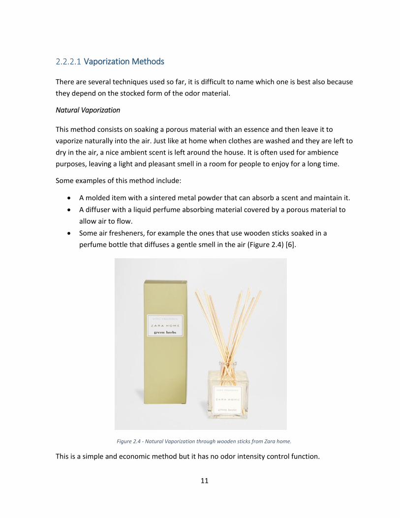
Natural Vaporization
This method consists on soaking a porous material with an essence and then leave it to
vaporize naturally into the air. Just like at home when clothes are washed and they are left to
dry in the air, a nice ambient scent is left around the house. It is often used for ambience
purposes, leaving a light and pleasant smell in a room for people to enjoy for a long time.
Some examples of this method include:
A molded item with a sintered metal powder that can absorb a scent and maintain it.
A diffuser with a liquid perfume absorbing material covered by a porous material to
allow air to flow.
Some air fresheners, for example the ones that use wooden sticks soaked in a
perfume bottle that diffuses a gentle smell in the air (Figure 2.4) [6].
This is a simple and economic method but it has no odor intensity control function.
Figure 2.4 - Natural Vaporization through wooden sticks from Zara home.

12
Airflow-Based Vaporization
It works by imposing an airflow by a surface of a scented material, of any form. The airflow
can be imposed by devices such as compressors, pumps or fans (Figure 2.5) [2]. It is a very
common solution, it is simple and it can be used for both stationary and wearable devices.
This method allows for a good control of the smell intensity and it can be combined with
several scent delivery methods, making it highly versatile.
Heating
This is a method has been used for many years now, for example the burning of incense
sticks. Another example, more common, would be the aroma candles. These work by placing
liquid perfume into a small heat resistant bowl, and then heated up by a candle or a small
lamp.
For simple ambience applications it is a good solution. In addition, because there are no
mechanical components, noise and vibration are inexistent. However, it is difficult to control
the volatilized volume through heat, which is a problem when switching quickly between
scents is required.
Figure 2.5 - Examples of devices with different layouts using Airflow-Based Vaporization

13
Despite the technical difficulties, Kim et al. [7] developed a prototype that works with these
principle. They used a hydrogel that changes phase according to the temperature, and with
precise control of the temperature, the scent intensity can be controlled.
Direct Atomization
Using an ink-jet head from a printer, droplets of a scented solution can be delivered when
required. This approach allows for great control of scent delivery, both temporal and
quantitative. This method was successfully applied by Yamada et al. [8] in creating a
Wearable Olfactory Display that will be further described in chapter 3.
For this method, there are two known delivery methods. On the first case, the droplets flow
through a delivery tube or a surface, an airflow needs to be induced to atomize these
droplets into tiny particles, as in a prototype developed by Yamada et al. [8] in 2006. On the
other case, Kadowaki et al. [9] created a prototype the droplets are delivered directly into
the user’s nostrils, which means that there is no separate delivery system.
Due to its simple structure, the ink-jet head is compact and simple structured making the
device easy to miniaturize. One ink-jet head is required for each smell but it is possible to
have a device with a satisfactory scent range without compromising user comfort too much.

14
Ultrasonic Atomization
This method uses ultrasonic vibrations on a liquid essence to generate fine scented particles.
When a high frequency voltage is applied to a disk shaped piezo electric component, a
resonance is created in the direction perpendicular to the disk surface, creating ultrasonic
sound waves that will propagate through the liquid. The result is a bulging effect of the
liquid’s surface that will result in its atomization into particles, creating a considerable
amount of mist (Figure 2.6) [10].
The threshold frequency of the ultrasonic waves to create mist is of 2 MHz. When this
frequency reaches 2.5 MHz, the mist particles become very thin with a diameter of less than
3 microns. Like this, the mist will feel less humid and hover the air more easily.
Scent Switching Technology
During a video game or a movie, a certain scene starts and the correct scent needs to be
delivered, this action requires a scent switching function. This function needs to be executed
quickly, and effectively with proper isolation from the other stored essences.
Figure 2.6 - Ultrasonic Atomization Principle.

15
Several methods have been proposed so far. Some are based on mechanical switching so
that a particular odor from the stored range is selected by moving its container. For example,
in a device where the scents are stored in the slots of a revolver-like component. Others are
based on airflow control where the air is directed to the desired container. One case would
be if the scents are stored in tubes with a piece of wet cloth inside, a fan driven airflow can
be directed to the desired tube. Another would be if a pneumatic based system is
considered, where the flow would have to be directed using pressure valves. The choice of
the right scent switching method depends largely on the other components of the system.
2.2.3 Scent Delivery Methods
Once an odor is vaporized, it has to be delivered to its target. The method of delivery
depends on the several aspects according to the application: how many people have to
receive the smell simultaneously, are these people moving and how quick the transition
between smells should be. In the case where scents have to be delivered to many people, for
example a theater room, a straightforward method would be to difuse smells into the intire
area. Logically, a considerable amount of odor particles would have to be difused. On the
other hand, when the scent is to be difused to a single individual, the target area has to be as
small as possible to avoid interfering with the people nearby. For these applications,
sometimes it is necessary to have some sort of enclosure.
The duration of the presence of a smell is a function of the delivered concentration. So the
ability to control its duration will depend on how quickly this concentration can be reduced
bellow the detection threshold. For example, odors presented over a large area will take a
while to dissipate the high amount of particles. On the contrary, when targeting small areas,
the required concentration is very low so the smell will fade away immediately. This is a
great advantage when coordinating an Olfactory Display with an Audio-Visual simulation
where the odor presentation has to keep up with different scenes.
This leads us to the problem of smell removal, because a new smell cannot be delivered
while the previous one is still present. There are two approaches to solve this issue: Using a
scent elimination function or delivering a minimum amount of scent particles to the user.
In the scent elimination method, the high concentration of the present odor is reduced with
the aid of various devices, according to the amount of smell to be removed. Until moderate
amounts, suction pumps or filters can be used. For higher concentrations, ventilation
systems are usually incorporated. Ventilation would be the appropriate for large size

16
dedicated installations such as theatre rooms or amusement park rides and simulators. But
due to its complexity and cost, it wouldn’t be fit for home or office use.
With the minimum material approach, scents dissipate naturally in the air quickly. In fact,
high values of odor concentration are required, but restricted to the smallest area possible.
In this way, the particles quickly spread to the surroundings, and the scent concentration
drops below the detection threshold almost immediately. The advantage is that there is no
need for an extra piece of equipment to remove the scents, but it will require a very well
designed scent delivery system to work properly.
In the next section, the various existing methods of scent delivery are presented.
Natural Diffusion/Convection
In this method, scents are allowed to travel freely throughout the air without any induced
intervention (Figure 2.7) [2]. Scents tend to move naturally to lower concentration areas,
usually there is always a slow airflow that helps the diffusing process. Therefore, the odors
emitted are gradually dispersed throughout the room evenly.
The traditional way of enjoying ambient aromas usually are through natural convection,
giving a long lasting experience to users with subtle variations. These smells are not felt as
clearly as with other methods, but still enough to provide information about the
surroundings.
This design is quite limited in terms of spatial-temporal distribution of smells, because the
ambient air flow is mainly responsible for this. In this type of design, the distance between
the user and the device is also important, as the smell intensity is stronger closer to the
source.
Figure 2.7 - Natural Convection Method.

17
Since the ambient air flow cannot be controlled and largely influences the experience,
reducing the distance between the display-user distances will mitigate its influence.
Therefore, wearable devices can achieve higher performances than its stationary
counterparts.
Imposed Wind/Airflow
Through a fan imposed airflow, scent particles can be carried to the nose with relative
accuracy. The device can be placed at a certain distance from the user and the odors are
noticed when they reach its target (Figure 2.8) [2]. This design allows for a good control over
scent duration and good scent switching performance. Of course the speed at which these
variations are felt depend on the air flow speed and distance traveled but there is always a
limit. If the airflow is too strong to make up for a considerable distance, it can cause
discomfort to the user.
Several designs have been based on this method with very different layouts and some
examples will be presented in chapter 3.
Figure 2.8 - Imposed Airflow.

18
Vortex Rings
When distances increase, devices using imposed airflow perform poorly at some point,
because the wind can be dispersed if it travels too far. In these situations, it is better to use a
Vortex Ring (Figure 2.9) [2] to convey the odor, where the emitted scent is encapsulated in
the vortex and can reach larger distances as long the ring shape is maintained.
To launch vortex rings, an air cannon is used. An air cannon is a device that contains an open
air chamber with a circular aperture. When the chamber volume is suddenly decreased, the
air is forced out of the chamber and generates a halo-shaped vortex (Figure 2.10) [11]. By
diffusing an odor inside this chamber, scented vortex ring can be launched.
The big advantage is that the scent can be delivered at much larger distances, until the ring
collapses upon collision with the user. The scents are delivered in pulses and not
continuously, so it is not suitable for providing a long lasting odor. In addition, the scent
Figure 2.9 - Vortex Ring Principle.
Figure 2.10 - Vortex Ring Generation through an Air Cannon.

19
amount that can be delivered is defined by the size of the aperture in the air cannon, and the
ambient wind can affect its performance.
Tubes
Delivering scents through tubes is a very effective method to make odors reach the user.
There is no risk of the scents being dispersed into the surroundings and the ambient
conditions have no influence. With the appropriate scent generation and switching
procedures, this method can deliver scents both continuously and in short-term pulses,
directly under the user’s nose (Figure 2.11).
On the downside, the scent particles can adhere to the inner wall of the tubes. When this
happens, smells that were presented previously get mixed with the current smell. To solve
this issue, sometimes the scent concentrations delivered have to be very low, or more
effectively a range of tubes can be used for each smell. This problem also depends on the
form in which the odor is stocked, where liquids based odors are more prone to contaminate
the inner walls of the tubes. In addition, attaching tubes to the user’s body is somewhat
cumbersome.
Scent
Generator
Compact Scent
Generator
Tubes
Figure 2.11 - Scent Delivery through Tubes. On the left a stationary device, and on the left a wearable one.

20
2.3 Olfactory Display Evaluation
Any type of system has its performance measures. When designing olfactory displays, there
are essential factors that measure it up against the competition, and serve as goals for the
next designer. So in this section, the relevant parameters are presented.
Generally, there are two ways to evaluate olfactory displays: one is to evaluate the
performance of the device itself and the other is too evaluate the effect on users. The focus
will be on the first approach, and the factors to determine the performance of olfactory
displays are described below. There can be more factors according to other people, but in
this case these were the ones worth considering.
2.3.1 Performance Evaluation Parameters
Maximum Ability of Atomization/Vaporization
It measures the amount of scent that can be delivered at once. When the target area is large,
this becomes more relevant since users would not be able to feel the scent clearly if the
vaporization capability is not sufficient. However, if the delivery is localized, this factor loses
importance since the necessary odor concentration to be diffused is reduced.
Number of Odor Components
Logically, the more odor options a device has to offer the better. The necessary amount
varies with the application and is not a defined number, but having more options makes the
device immediately more versatile. Some devices are able to generate new odors by
combining the base scents included, but most of the times this does not work that well and
of course it is always better to use the original. However, advances have been made in
blending scents and it is likely to become widely utilized in the future.
Dynamic Range
Basically, it is how many levels of odor intensity there are to choose from. A scent generator
with a large dynamic range can control the amount or concentration of each odor
component precisely. One good example of high dynamic range would be the ink-jet
olfactory display developed by Kadowaki et al. [9] (3.2.2) that has 256 levels of intensity.
21
Accuracy
It can also be referred as stability or repeatability, it measures the ability to keep the odor
concentration level constant, matching the desired value. This capacity depends on the type
of scent generation. For example, in scent generators using airflow-based vaporization, the
concentration of odor material depends on the velocity of the imposed airflow. In these
cases, making sure the airflow characteristics are constant is paramount to ensure a constant
odor intensity.
Crosstalk
Crosstalk refers to the phenomenon that unintended odor component(s) are mixed in the
desired combination of odor components. This can happen more commonly for example, on
tube based systems. If a tube long tube is used to deliver the scent, odors can adhere to the
walls. On the other hand, the cooling-based scent generator developed by Kim et al. [7]
proved very good in this matter, as the odors don’t are vaporized into the air directly
through heating.
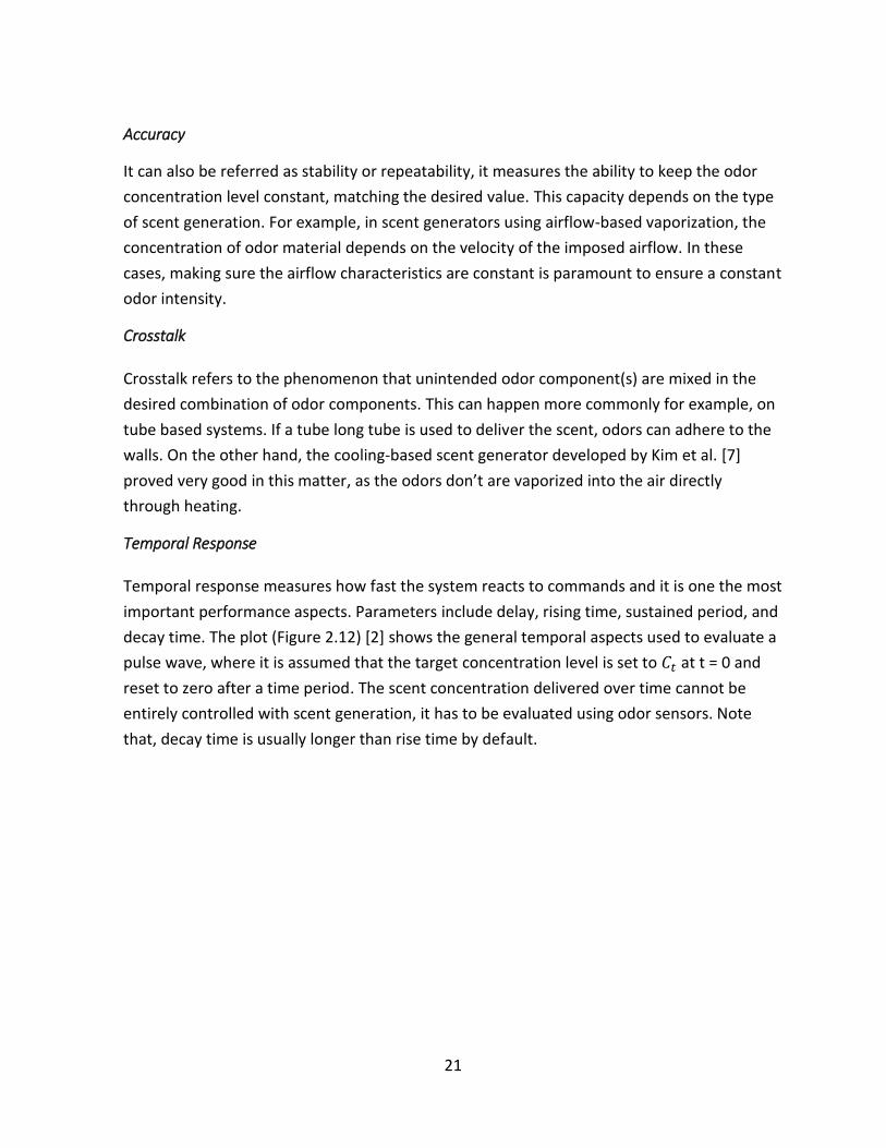
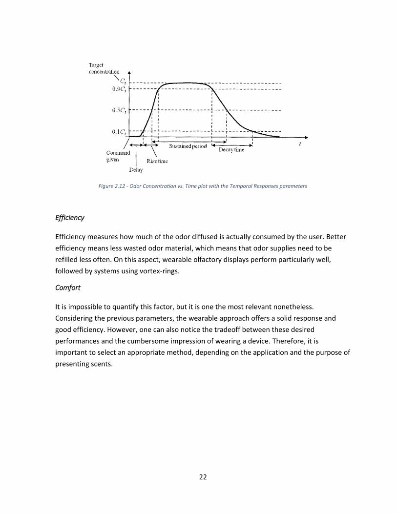
Temporal Response
Temporal response measures how fast the system reacts to commands and it is one the most
important performance aspects. Parameters include delay, rising time, sustained period, and
decay time. The plot (Figure 2.12) [2] shows the general temporal aspects used to evaluate a
pulse wave, where it is assumed that the target concentration level is set to 𝐶𝑡 at t = 0 and
reset to zero after a time period. The scent concentration delivered over time cannot be
entirely controlled with scent generation, it has to be evaluated using odor sensors. Note
that, decay time is usually longer than rise time by default.
22
Efficiency
Efficiency measures how much of the odor diffused is actually consumed by the user. Better
efficiency means less wasted odor material, which means that odor supplies need to be
refilled less often. On this aspect, wearable olfactory displays perform particularly well,
followed by systems using vortex-rings.
Comfort
It is impossible to quantify this factor, but it is one the most relevant nonetheless.
Considering the previous parameters, the wearable approach offers a solid response and
good efficiency. However, one can also notice the tradeoff between these desired
performances and the cumbersome impression of wearing a device. Therefore, it is
important to select an appropriate method, depending on the application and the purpose of
presenting scents.
Figure 2.12 - Odor Concentration vs. Time plot with the Temporal Responses parameters

23
State of The Art
The Olfactory Display devices developed so far are as numerous as they are diverse, even
though it is considered to be a relatively new field. One of the main reasons for this could be
that there hasn’t been a system that had a significant commercial impact.
In this section the most relevant related works are presented, including academic researches
and industrial products. In some cases, several projects were launched by the same group of
people, because they have been researching on this topic continuously for quite some time.
These developments are organized by scent delivery method, like in the previous chapter.
And within each category, it follows a chronological order.
3.1 Natural Convection Systems
As mentioned before, the first use of scent display to enhance the “realness” of a simulation
dates back to the beginning of the XX century, and it used natural convection. The
conjunction of film and theatre started in 1906, when a Philadelphia cinema owner named
S.L. Rothafel sprayed the audience with the scent of roses during a screening of the Rose
Bowl [12].
3.1.1 Joseph Kaye’s MIT Research Projects - 2001
During his MIT Master of Science, Joseph Kaye [12] wanted to explore the possibilities of
conveying information using scent. The ultimate goal was to use olfactory as a
communication channel, in the same way as computers can play music.
Within this scope, he developed 5 prototypes that caused some impact in the field. The
importance of his work is not related to the development of technological wonders in the
device’s hardware, but the introduction of very innovative and useful ideas using smells in
common day-to-day situations. In fact, the systems are relatively simple, suggesting that the
integration of this technology in our everyday lives could be implemented sooner than
expected.
The scope of this thesis is more about ways to build olfactory displays, rather than possible
uses for the technology. Nevertheless, the sheer creativity in these ideas backed by a strong

24
knowledge about human behavior lead to the development of very interesting work. Such
ideas have shown that there might be a relevant marketability in the world of Olfactory
Displays after all.
“inStink” - February 2000
Let’s imagine the situation of being abroad, and one is missing the little things that make
home feel like home, like the smell of home cooking. The goal here is to develop a device
that brings that sensation to the user, even though home is very far.
Ideally, to recreate environments as accurate as possible, the system would have an
electronic nose at home that could recognize the smells, and communicate with the other
end which would recreate the odor to be presented.
Since this wasn’t possible, there is a spice rack at home and a device that detects when a
specific spice is being used. On the other end, a range of scents of those spices is available so
that the spice being used at home can be diffused (Figure 3.1) [12].
The two components of the system work as follows. The first part, at home, consists of a
spice rack with a contact sensor attached to each specific spice jar (Figure 3.1). A
programmable board receives the signals from these sensors. These signals are then sent to
the other end, where smells were diffused using individual airbrushes (airbrushes pic). These
airbrushes would be controlled by another programmable board that controls a valve system
fed by a CO2 tank or a small air compressor (Figure 3.2).
Figure 3.1 - Spice rack at home with contact sensors

25
In terms of getting a real experience, the device is limited to the available spices, leaving out
all other cooking smells. In terms of scent generation and delivery, both functions worked
without problems. However, it is a complex and expensive system that would not be fit to
adapt to a Wearable version. The main issues are related to the quality of the smells, and the
impossibility to recreate an olfactory experience that accurately matches the user’s memory.
“Dollars & Scents” - October 2000
The second project was a lot simpler. The idea came from a previous thesis by Wisneski [13],
who designed a pocket device to present information of the stock market to the user by
becoming hot or cold. In addition, through research Ren [14] discovered that people wish to
be aware of the state of the market but do not want to dedicate full attention to a detailed
analysis constantly. Therefore, displays can give an idea of the market without disrupting the
attention of the user.
So, the system consists of two spray bottles that are operated by two solenoid valves (Figure
3.3). The two solenoids are controlled by a single-board TINI computer, which launches the
smell of mint if the market is going up, and lemon if the market is going down. The force
required to push down the plunger of the perfume bottle demands a large solenoid valve,
which requires considerable power and room to accommodate.
Figure 3.2 - Each scent is diffused using an assigned airbrush

26
The response was generally positive, the device did not cause any discomfort and people
enjoyed it. There was also the idea of regulating the intensity according to the level of the
market rise/drop, but this would require an almost still airflow in the ambient and people
adapt to scents very quickly, which would allow only to note the smell changing [12].
Using the same technology, Kaye came up with two more devices: “Scent Reminder” (Figure
3.4), a computer controlled “olfactory schedule” that works in conjunction with Microsoft
Outlook, diffusing a specific smell to remind the subject of a specific event. And, “Honey, I’m
Home” (Figure 3.4) [12], a new concept conceived by the author and accurately described in
the following quoted piece of text: “On my girlfriend’s desk sits a small, rounded, black box.
At the back of my desk is light blue acrylic structure. When my girlfriend wants me to know
she’s thinking of me, she rests her hand on the box for a couple of seconds. A gentle, warm
scent of hazelnut wafts across my desk, without interrupting my meetings or phone calls. It’s
good to know you’re loved.”
Figure 3.3 - Dollars & Scents display with the twin solenoids and the perfume bottles.

27
3.1.2 iSmell - 2001
In 2001 Digiscents announced iSmell, a computer controlled device that could spray scents to
its user while accessing a website or opening an email. The company initially started with
working on movie clips with integrated sequences of smell in a project called “Scentracks”
[12].
After an enthusiastic article was published in Wired Magazine, the company decided to
produce a device for home use. It would be controlled by USB or serial port and it would
contain a cartridge of 128 primary odors that could be mixed to replicate a wide range of
smells [15] (Figure 3.5) [16].
Figure 3.4 - On the left, Scent Reminder with 5 different odors. On the right, the input side of Honey I'm Home, a small and discrete black box that is comfortable to touch.
Figure 3.5 - iSmell prototypes by Digiscents

28
The company announced in fall 2000 that it would start commercializing the product in the
following spring, but by April 2001 not even the developers had hardware devices. The
prototyping phase was never finished and shortly after, the company bankrupted. It became
famous because there was a hype about the announcement on the internet, but the
standard was set too high for the Digiscents to ever come through with a viable solution.
3.1.3 Aroma-Card Soundless Olfactory Display - 2009
The research group led by Kim et al. [7] presented a rather innovative approach. Usually,
electro mechanical devices are used to deliver the scents such as fans and compressors.
Therefore, most of the times these devices are noisy and vibrate to some extent, even
though there are fans that are barely noticeable. As solution, the system uses a temperature
responsive hydrogel for each scent that alters between sol and gel (Figure 3.6) [7], and so it
aroma release is accurately controlled by a “Peltier” module to control the temperature.
The scents are stored into 15 chips that are placed on top of 15 “Peltier” modules, a thermo-
electric cooling device used upside down to provide heat, and their temperature is controlled
individually by a computer. This board that includes the 15 aroma-chips and “Peltier”
modules is called the aroma-card and is located at the top of the device (Figure 3.7) [7].
Figure 3.6 - Transition between Gel at 25°C (on the left) and Sol at 60°C (on the right)

29
The results showed potential although there are some inherent disadvantages. The
responsiveness of the system is slow since it takes about 10s between the heating start and
the user noticing a smell intensity variation. Apart from the reduced noise, there is no
adhesion of scent particles to the device since the aroma-chips sit on top.
3.2 Imposed Airflow Systems
Since that first scented theatre experience in 1906, fifty years had passed until the next
development. With the television boom in the late fifties, Cinema owners were worried that
their clientele would be reduced. And so, they looked for new ways to make cinema-going a
more attractive activity.
In this context, AromaRama came out in December 1959, mixing smells with a travelogue of
China called “Behind the Great Wall” [12]. The system used Freon gas to diffuse smells using
the air conditioning ducts to the theatre rooms. It created an expectation that did not match
reality: odors seemed fake, they were strong enough to cause headaches to some of the
viewers and they weren’t removed quickly enough to keep up with the scenes changing. One
year later, Smell-o-Vision (Figure 3.8) [12] was presented and despite a more complex
system using a tube for each seat to deliver scents, it failed to impress the critics as well.
Figure 3.7 - Aroma-Card with the 15 aroma-chips and the Peltier modules

30
These earlier systems were used for large scale applications and made evident several
problems in Olfactory Displays, namely smell removal. Knowing this, several systems came
out decades later that provided far better results using the same delivery system.
3.2.1 Scent Collar - 2003
Scent Collar [17] is a wearable olfactory display created by the Institute for Creative
Technologies at the University of Southern California. With both aesthetics and functionality
in mind, the Scent Collar is a collar shaped device that was designed to be used with virtual
reality simulations.
To avoid contaminating the air in simulations, a minimum amount of odor is diffused. For
this to work the device needs to be close to the users face. Hence, the collar design. The
components were meant to be as compact as possible to maximize the scent range without
jeopardizing comfort.
Ultimately, the presented prototype (Figure 3.9) [17] houses 4 scents that were stocked as
oil-soaked wicks in individual slots and then diffused using small fans. The device is
controlled by Bluetooth in a virtual space with scent-marked zones for the user to move
around: scents are activated when the wearer enters a marked location of the virtual space.
Figure 3.8 - Smell-O-Vision was introduced in the movie Scent of Mystery, a film deliberately created for being displayed with smell.
31
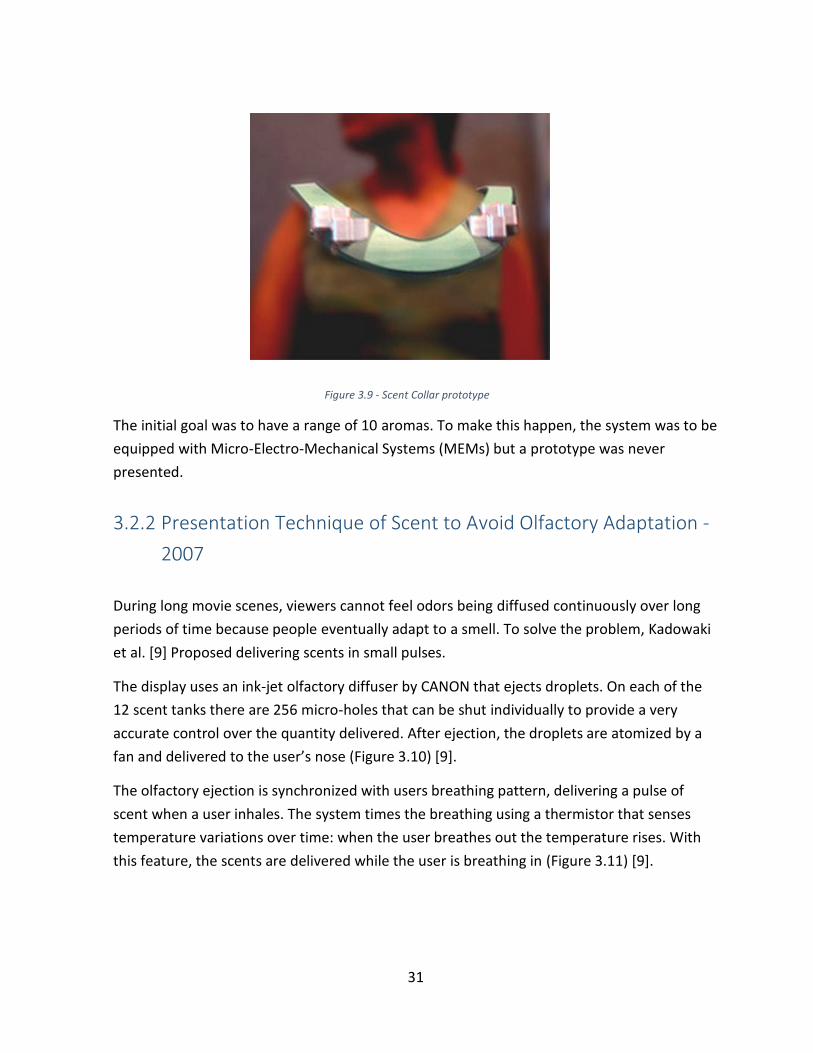
The initial goal was to have a range of 10 aromas. To make this happen, the system was to be
equipped with Micro-Electro-Mechanical Systems (MEMs) but a prototype was never
presented.
3.2.2 Presentation Technique of Scent to Avoid Olfactory Adaptation -
2007
During long movie scenes, viewers cannot feel odors being diffused continuously over long
periods of time because people eventually adapt to a smell. To solve the problem, Kadowaki
et al. [9] Proposed delivering scents in small pulses.
The display uses an ink-jet olfactory diffuser by CANON that ejects droplets. On each of the
12 scent tanks there are 256 micro-holes that can be shut individually to provide a very
accurate control over the quantity delivered. After ejection, the droplets are atomized by a
fan and delivered to the user’s nose (Figure 3.10) [9].
The olfactory ejection is synchronized with users breathing pattern, delivering a pulse of
scent when a user inhales. The system times the breathing using a thermistor that senses
temperature variations over time: when the user breathes out the temperature rises. With
this feature, the scents are delivered while the user is breathing in (Figure 3.11) [9].
Figure 3.9 - Scent Collar prototype

32
The results were satisfactory, users could feel the same scent for a longer period. Although
this device is highly complex and it does not consider usability and comfort for the user.
Apart from that, it requires a complex and expensive apparatus. Nevertheless, a pulsed smell
delivery pattern can be used in several other types of stationery and wearable devices and
improve the quality of the simulation.
3.3 Systems Using Vortex Rings
The interest of these systems came about with the limited range of fans in delivering scents
over a certain distance with a considerable accuracy and wasting less amount of scent. The
Figure 3.10 - Prototype testing
Figure 3.11 - Scent delivery pattern synced with breathing

33
fact is that there aren’t that many systems out there that use vortex rings: maybe because
there is not a big enough demand of its distance capabilities, or maybe because the
apparatus is too complex to attract people researching into it. However, this method is new
when compared to the other ones and maybe be the right solution for a specific application.
3.3.1 Methods and Apparatus for localized delivery of scented
aerosols - 2002
This display developed by Carl J. Watkins [18] is the first to use a Vortex Ring. It is composed
by a box that with an orifice and it houses a speaker and multi-scent generator inside. The
size and distance reached by the ring can be adjusted by changing the orifice diameter
(Figure 3.12) [18] and the frequency of the pulse.
Before a vortex ring is launched, the inner chamber needs to be filled with scented air. The
scent generator contains several (number not specified) recipients of liquid based aromas
that are connected to an electro-pneumatic system, using a valve system and a pressure line
to select the desired scent to permeate the air inside the chamber (Figure 3.13) [18]. There
are no reported tests or any results to prove the system was successful, but the concept was
indeed used for developing other devices.
Figure 3.12 - Air Cannon with orifice detail.

34
3.3.2 ATR Media Information Science Laboratories and Meijo
University Research - 2003 to 2011
The title of this section seems a bit odd but there is a reason for it. Throughout 8 years, a
group of Japanese scientists started developing an olfactory display using an air cannon.
Along the way they kept adding new features to it, new people appeared to help and 4
articles were published. So this section, will be divided into 4 subsections for each new
contribution to the system.
An Unencumbering, Localized Olfactory Display - 2003
The project was kicked off by Yanagida et al. [19] with the goal of making an Olfactory
Display to be included in the next-generation virtual reality systems. In the attempt of
making a device that performs well and promotes comfort by avoiding a wearable system,
the group proposes an “unencumbering” device (Figure 3.14) [19], using an air cannon to
deliver the scents with precision.
An air cannon was developed, keeping in mind that the scent emission has to be launched to
a precise area. Accuracy was a top priority. This way, wasted odor material is reduced and
different scents can be displayed to multiple users. To make sure the air cannon is aiming at
the right place, a face tracking system was developed to include in the system. The tracking
Figure 3.13 - Scent selector system detail inside the air cannon chamber
35
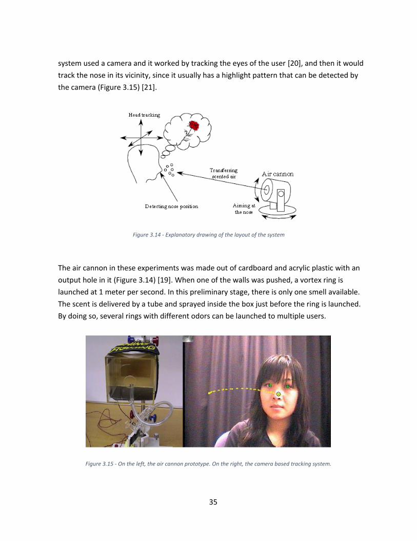
system used a camera and it worked by tracking the eyes of the user [20], and then it would
track the nose in its vicinity, since it usually has a highlight pattern that can be detected by
the camera (Figure 3.15) [21].
The air cannon in these experiments was made out of cardboard and acrylic plastic with an
output hole in it (Figure 3.14) [19]. When one of the walls was pushed, a vortex ring is
launched at 1 meter per second. In this preliminary stage, there is only one smell available.
The scent is delivered by a tube and sprayed inside the box just before the ring is launched.
By doing so, several rings with different odors can be launched to multiple users.
Figure 3.14 - Explanatory drawing of the layout of the system
Figure 3.15 - On the left, the air cannon prototype. On the right, the camera based tracking system.

36
The results were promising: out of 59 launch attempts there were 11 failed, and 9 missed
hits. Out the remaining 39 that reached the targets, there was a smell detection rate of 72%
(28 out of 39). From this point, the focus was on improving the design of the air cannon and
the inclusion of a scent switching function.
Projection-Based Olfactory Display with Nose Tracking - 2004
On this second step of the research, which is actually the 3rd prototype developed by the
group, a scent switching function was integrated by Yanagida et al. [21]. The issue was that
by ejecting the scent inside the air cannon chamber, the smell would not clean properly with
the vortex ring launch. Cleaning the scent from the chamber would be difficult, and also the
air cannon could be improved, so a new one was built.
The new air cannon sits on a 2-DOF custom made platform that is connected to the camera,
like in the previous model. The volume variation was increased in this model by including an
accordion-like chamber (Figure 3.16) [21] that is controlled by a stepping motor. To solve the
problem of scent switching, a short cylinder with the same diameter as the aperture of the
air cannon was added and it included mechanical shutters at both ends. On the side faces of
the cylinder, 4 holes were made for scent delivery and 1 hole for cleaning. Attached to these
holes are tubes that are managed by an electro-pneumatic system controlled by an outside
computer.
Figure 3.16 - Third prototype of the air cannon. Notice the accordion-like section to allow for a greater volume variation

37
SpotScents: A Novel Method of Natural Scent Delivery Using Multiple Scent Projectors - 2006
Having satisfying the basic requirements, the research focused on fine tuning the experience.
With the current system, users felt a strong unnatural airflow when the vortex ring would hit
their faces. To reduce this effect, Nakaizumi et al. [22] used two air cannons to launch vortex
rings that collide close to the users face. Upon collision, the rings break and smell is
distributed around a small area or “spot”. With this configuration users felt a gentle scented
breeze, and the experience became a lot more pleasant (Figure 3.17) [22].
The results showed that there was in fact a reduced airflow around the target points.
However, the range of the scent delivery is reduced compared to just using a single air
cannon. It proved hard to ensure an accurate collision above 1100 mm.
Localized Scent Presentation to a Walking Person by Using Scent Projectors - 2011
The system could detect the user’s face to deliver the smell, but they could not be applied to
a moving person. In this experiment, Murai et al. [23] included a time-of-flight base range
imaging camera to track a user entering the area of interest. In the experiment, it is assumed
that the user is walking in a straight line at constant speed, in an attempt to recreate an aisle
of a super market.
Figure 3.17 - On the left, single vortex ring hitting the user's face. On the right, the new solution where a gentle breeze reaches the user's face

38
The system layout is shown in the (Figure 3.18) [23], two air cannons are set 1m apart. The
system calculates the user’s velocity and aims two vortex rings to collide 50 cm in front of
the users estimated position. As a system that has an inherently small margin for error, the
results were not very satisfactory. Only 66% of the experiments were successful in making
the user perceive the smell.
3.4 Systems Using Tubes
3.4.1 A CPU-controlled olfactometer for fMRI and electrophysiological
studies of olfaction -1999
This is a design for a reliable and economical olfactory display. Using an electro pneumatic
system, with pressure lines and solenoid valves, a system was created by Lorig et al. [24] that
works seamlessly, ensuring quick rise times, effective scent switching and cleaning.
The use of electro pneumatic circuits in Olfactory Displays has been proved to be very
effective. Joining that to tube delivery, and an accurate localized delivery is guaranteed.
However, this system is as good as it gets the way it is. There can be issues with odor
adhesion to the tubes and in this configuration, this concept could not be further developed
into a compact/portable device.
This system is a great introduction to exemplify the potential of tubes. Yet, to get a wearable
device or a more compact solution, different scent generation and delivery technologies
need to be used. The following projects are remarkable efforts in making wearable devices.
Figure 3.18 - System layout with the two vortexes colliding in front of the user.

39
3.4.2 Fragra: A Visual-Olfactory VR Game - 2004
By understanding the relationship between olfaction and vision, our lives can be enhanced
by communicating through the olfactory channel: cooking programs that allows us to smell
the dishes on demand, a new type of restaurant menu which we can see and also smell. With
this in mind, Mochizuki et al. [25] developed a visual-olfactory display device along with a
game “Fragra” to research the interaction between these two scents.
The idea was to simulate the action of a person grabbing a piece of food or flower, to smell it
by approaching it to the nose. Scented air is delivered through tubes to the user’s hand, on
the contrary to the face like most devices. The system detects the hand approaching the
user’s nose, by using a camera and markers on the user’s hand (Figure 3.19 left) [25], and
then it delivers the smell. The scent is selected using a PC controlled solenoid bulb according
to the object displayed in the game (Figure 3.19 right) [25].
3.4.3 D.I.V.E. Firefighter training system - 2001
The Deep Immersion Virtual Environment Laboratory at the Southwest Research Institute in
1992 started developing a firefighter training system: an olfactory display designed to train
firefighters delivering odors in fire simulations.
Lead by John Cater [12] [26] [27], the team developed a backpack mounted device (Figure
3.20) [27], with scents delivered through the oxygen mask that is used in the regular
firefighter equipment. The system proved itself from the beginning, and so developments
came with the years.
Figure 3.19 - On the left, camera detects hand approaching the user’s nose. On the right, screenshot of the simulation with the user approaching a banana to his nose.

40
The odor quality was improved and the scent selection range as well. The final design in
2001, used fluid essential oil wicks developed in conjunction with Fragrance Technologies of
Windermere, Florida that produced the best results achieved so far. The most impressive
feature of the device, is that the olfactory output that ranges from a barely noticeable odor
to an “unbearable stench that makes you want to rip the mask off” (Figure 3.21) [27].
Figure 3.20 - D.I.V.E. Firefighter training system.
Figure 3.21 - D.I.V.E. Firefighter training system in use

41
3.4.4 Wearable Olfactory Display: Using Odor in Outdoor Environment
- 2006
Besides creating a device, in this work by Yamada et al. [8] the goal of this was also to create
a virtual space where scents vary in type and intensity according to the user’s position. So, in
this research, a wearable olfactory display was created that delivers odors in the gaseous
state and uses tubes to deliver it to the user’s nose.
The device’s odor generating and control units are “worn” as a backpack. The tubes come
from the backpack and arrive at a Head Mounted device. The odors arrive from several tubes
at a larger cylinder that is located under the user’s nose, and they are delivered through tiny
side holes of this cylinder (Figure 3.22) [8]. The system also includes a tag reader, to read
markers on the floor that enable to detect the odor sources and create the odor field (Figure
3.23) [8].
Figure 3.22 - Odor-Presenting Unit to be place under the nose

42
The odor delivery increases strength when the user reaches any of the sources. The airflow is
generated by a DC pump. Since the system has a tube for each odor and one tube for clean
air, the strength of the presented smell is controlled by managing the proportion between
non-odor airflow and odor airflow.
In addition, the research group developed another prototype but with a different scent
delivery method that wasn’t referred beforehand - Direct Injection. This system can be
described by not having a delivery method per se, scents are generated at the user’s nose
and so they don’t need to be “carried”. This is achieved by placing several ink-jet heads, like
the ones seen before, close the user’s nose. Apart from that, the system uses a breath
detection unit that tells the control unit when to deliver the scents, to avoid a continuous
pattern. To have successfully integrated these components into a wearable device (Figure
3.24) [8] is a remarkable achievement, even though user comfort is extremely compromised.
Figure 3.23 - On the top, virtual representation of a real scent field. On the bottom, the prototype and its components.
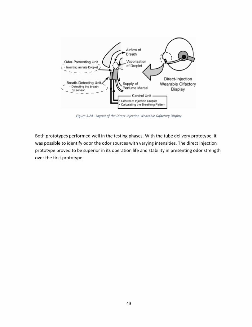
43
Both prototypes performed well in the testing phases. With the tube delivery prototype, it
was possible to identify odor the odor sources with varying intensities. The direct injection
prototype proved to be superior in its operation life and stability in presenting odor strength
over the first prototype.
Figure 3.24 - Layout of the Direct-Injection Wearable Olfactory Display

44

45
Problem Statement
The goal of this project was to develop a wearable olfactory display for Augmented Reality
and Virtual Reality purposes. More specifically, the scope of the project was to develop a
working prototype of an Olfactory Display that would serve as the base for further
developments, and to create a wireless connection system that would enable the device to
be controlled at a distance, a key element in making the device more compact and it´s use
more comfortable.
As a key element on the scope of this project, the creation of a functioning wireless system is
just not enough. To make it viable, it must be within a certain cost range without
compromising on reliability. In addition, the power source would have to be portable as well.
Addressing these issues was one of the goals of this project, even though they seem to be
frequently overlooked.
The novel feature of this device is the scent storage form. Most devices use either liquid or
gas based aromas, this device uses cartridges of compacted scented powder produced by the
company OIKOS fragrances [28]. The company makes scent diffusers for ambient uses using
an innovative patented method of scent storage and delivery called SFR (Solid Fragrance
Release). It is a simple principle: by applying a gentle airflow on the solid scent cartridges
that release particles in the air. This technology has some advantages compared to the
traditional ones that open up new possibilities in Olfactory Display design.
Often, Olfactory Displays are complex systems. There seems to be a generalized focus on
making perfect smell delivery systems, and usually researchers focus on innovative and
complicated technological solutions. Mostly, the results of these developments are
satisfactory but usability and practicality are usually not taken into account. Despite
interesting, the concepts presented are too complex to ever be used in the real world and so
they never leave the laboratory.
As a result, there is very little commercial interest in the topic. Devices exist, they can deliver
smells, but simulations lack appeal and a sense of reality. It can be conclude that the majority
of the research done, lacks a commercial drive. Developers often neglect ergonomical
aspects such as comfort, wearability and design feasibility in their developments.

46
On the contrary, the design proposed here aims for simplicity, low cost and user-friendliness,
without disregarding a possible marketability of the end product. The OIKOS scent cartridges
due to its easy scent delivery mechanism, are more than adequate for such an application.
More concretely, the objective is to assure the main functions of an olfactory display - scent
generation, selection and delivery - and a wireless control unit with a simple interface. In
addition, some guidelines were to be followed:
1. In a later stage, the end product is a wearable device. In other words, the end
product has to be compact, simple, and comfortable, so whatever is developed in this
early stage needs to be convertible to suit the final design requirements.
2. Costs are to be kept low, which means the device can only include simple prototyping
mechanisms that are simple, reliable and economic.
4.1 Possible Applications
To fully understand the importance of any innovation, it is essential to know what it is for.
There are many approaches into designing Olfactory Displays, but the right choice depends
on its future application. In this part, some possible uses are presented for this technology.
Cinema and Movies
As it was presented before, the first goal of an olfactory display was to enhance the
experience of watching a movie by coordinating scents with the apropriate scenes. The first
ever application was in 1906 when S.L. Rothafel sprayed the audience with a rose scent
during the screening of the Rose Bowl, the most important event in American college
football. After that, examples include AromaRama in 1959 and Smell-O-Vision one year after
by delivering different a range of scents to the audience. Another way to deliver scents was
to use scratch and sniff cards that were first used in the 1980s until the early 2000s with the
Spy Kids franchise [12]. Initially this created quite a buzz but the actual experience could
never match the expectation, so it never really became popular.
Virtual Reality and Gaming
More recently, the rising popularity of simulations opened a window for the use of olfactory
displays. For amusement purposes, some video games included scents. Examples include
“Fragra: A Visual-Olfactory VR Game” [25], the iSmell device by Digiscents [12] that never
cleared the prototyping phase and the device developed by Nakamoto et al. [29] that

47
attempted to create a cooking game that would release smells of each added ingredient to a
virtual sauce pan. With a different purpose but within the topic of simulations, the D.I.V.E.
Firefighter training system [12] delivered smells using the mask in the American standard
firefighter equipment to simulate fire situations for training. Also, it was noted that surgery
simulations in medical schools used to train future surgeons lacked a crucial olfaction
component in their simulations. Through smells, doctors can detect infections amongst other
things. However, creating accurate smells that resemble the real ones is too difficult, so such
a device was never developed.
Medical
Aromas can have a therapeutic effect on people and many ancient civilizations were aware
of this. The use of essential oils for therapeutic, spiritual, hygienic and ritualistic purposes
goes back to a number of ancient civilizations including the Chinese, Indians, Egyptians,
Greeks, and Romans who used them in cosmetics, perfumes and drugs [30] thus inventing
Aromatherapy. In addition, some olfactory displays may include an air purification function.
Through a chemical reaction between the scented air and the ambient air, some undesirable
elements may be eliminated.
Memory Triggering
It is known that smells have memories associated to them and this idea has been explored to
develop innovative concepts. The Jorvik Viking Museum in York, England for example, used
odors that successfully increased people’s ability to remember the information presented at
the exhibit [12]. Another example is the work developed at the University of Glasgow by
Stephen Brewster et al. [31] that tried to adapt the memory triggering effect to help browse
to large digital photo collections, attempting to assign smell tags to specific pictures that
would help the user to recall them while looking for them. A side effect of recalling
memories through smells is the triggering of associated emotions. One idea was to enable
couples to send scent signals to one another while they would be apart, a concept explored
by Joseph Kaye’s “Honey, I’m Home” [12] at MIT.

48

49
The Olfactory Display
5.1 Design Layout
In this part, the system architecture of the system is presented (Figure 5.1). That is, the
overall layout of the system to present a general perspective to the reader. A more detailed
explanation of each element will be presented subsequently.
As mentioned before, the system is composed by the Olfactory Display device and the
Control Unit. The Olfactory Display is, to put it briefly, a tube-based system where air flows
through. Within the Olfactory Display, there are 3 key functions:
Figure 5.1 - System Architecture: Layout of the system functions

50
Scent Generation - The odor is released by imposing an airflow on the scent
cartridges place inside small PVC tubes. The airflow is created by a Direct Current (DC)
powered fan that releases odor particles through an erosion process.
Scent Selection - The different scent types are placed inside tubes, each tube
corresponds to a specific scent, except for one of that is intentionally empty for the
cleaning function. The tubes are fixed to a rotating cylinder, similar to a revolver gun.
Using a servo motor, the cylinder rotates to the desired position to select a specific
smell to be delivered.
Scent Delivery - After passing through one of the tubes of the selector cylinder, the
scent goes through a flexible plastic tube to be delivered close to the user’s nose.
The Olfactory Display Prototype
Figure 5.2 - 3D Model of the Olfactory Display Prototype
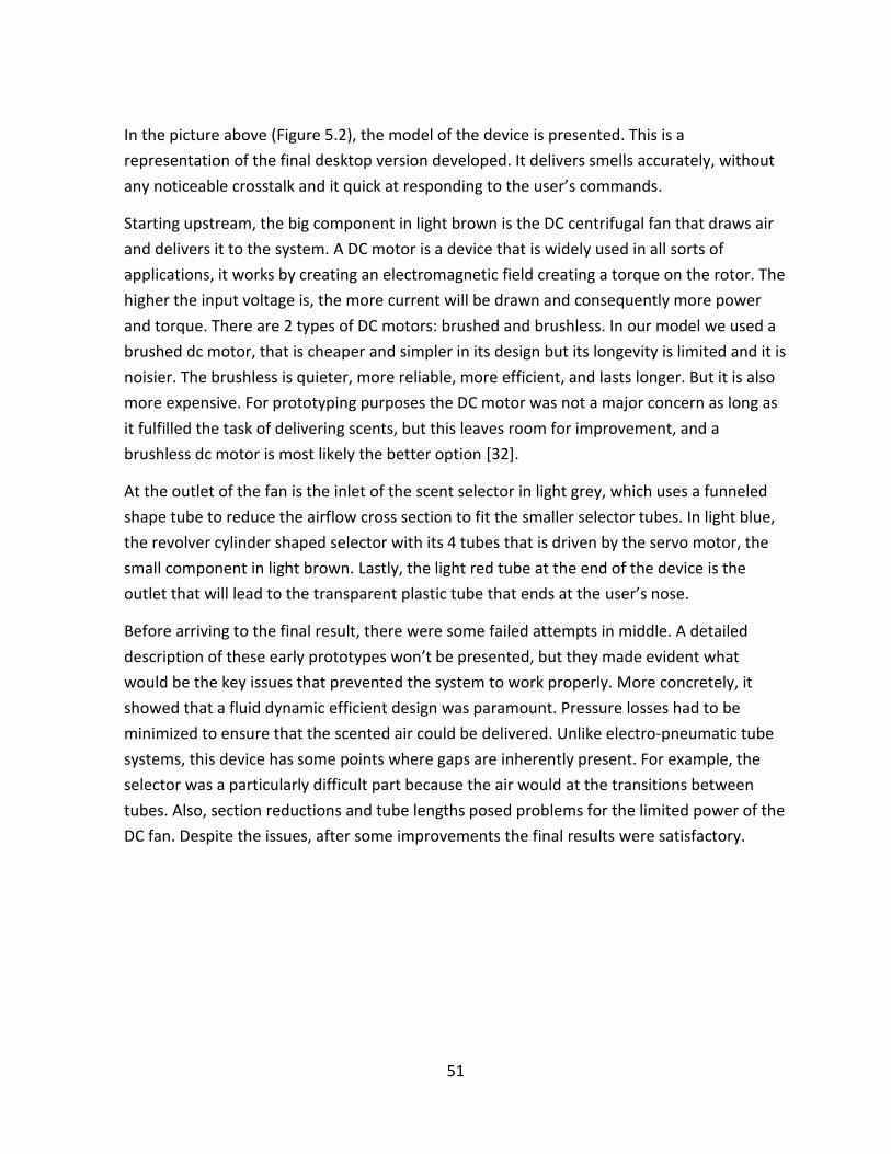
51
In the picture above (Figure 5.2), the model of the device is presented. This is a
representation of the final desktop version developed. It delivers smells accurately, without
any noticeable crosstalk and it quick at responding to the user’s commands.
Starting upstream, the big component in light brown is the DC centrifugal fan that draws air
and delivers it to the system. A DC motor is a device that is widely used in all sorts of
applications, it works by creating an electromagnetic field creating a torque on the rotor. The
higher the input voltage is, the more current will be drawn and consequently more power
and torque. There are 2 types of DC motors: brushed and brushless. In our model we used a
brushed dc motor, that is cheaper and simpler in its design but its longevity is limited and it is
noisier. The brushless is quieter, more reliable, more efficient, and lasts longer. But it is also
more expensive. For prototyping purposes the DC motor was not a major concern as long as
it fulfilled the task of delivering scents, but this leaves room for improvement, and a
brushless dc motor is most likely the better option [32].
At the outlet of the fan is the inlet of the scent selector in light grey, which uses a funneled
shape tube to reduce the airflow cross section to fit the smaller selector tubes. In light blue,
the revolver cylinder shaped selector with its 4 tubes that is driven by the servo motor, the
small component in light brown. Lastly, the light red tube at the end of the device is the
outlet that will lead to the transparent plastic tube that ends at the user’s nose.
Before arriving to the final result, there were some failed attempts in middle. A detailed
description of these early prototypes won’t be presented, but they made evident what
would be the key issues that prevented the system to work properly. More concretely, it
showed that a fluid dynamic efficient design was paramount. Pressure losses had to be
minimized to ensure that the scented air could be delivered. Unlike electro-pneumatic tube
systems, this device has some points where gaps are inherently present. For example, the
selector was a particularly difficult part because the air would at the transitions between
tubes. Also, section reductions and tube lengths posed problems for the limited power of the
DC fan. Despite the issues, after some improvements the final results were satisfactory.

52
5.2 Implementation
Scent Generation
The OIKOS scents are stored as a compacted powder inside small metal cartridges (Figure
5.3) [33] that come in several sizes to suit each of the company’s products. As mentioned
before, the company produces ambient scent diffusers mainly for hotels, events and stores.
Rather than just diffusing nice smells for people to enjoy, it considers the psychological
effects of smell on people for marketing purposes and it studies the chemical interaction of
the scent and the air to also include air purification capabilities.
Figure 5.3 - OIKOS Scent Cartridges: On the left, the scented powder. In the Center, a cartridge with the compacted powder. On the right, the cartridge used in the prototype.
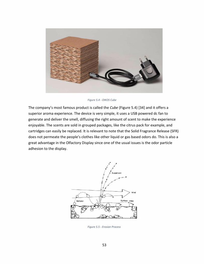
53
The company’s most famous product is called the Cube (Figure 5.4) [34] and it offers a
superior aroma experience. The device is very simple, it uses a USB powered dc fan to
generate and deliver the smell, diffusing the right amount of scent to make the experience
enjoyable. The scents are sold in grouped packages, like the citrus pack for example, and
cartridges can easily be replaced. It is relevant to note that the Solid Fragrance Release (SFR)
does not permeate the people’s clothes like other liquid or gas based odors do. This is also a
great advantage in the Olfactory Display since one of the usual issues is the odor particle
adhesion to the display.
Figure 5.4 - OIKOS Cube
Figure 5.5 - Erosion Process

54
The scent release mechanism depends on the airflow interaction with the cartridges. The
passing air creates an erosion effect (Figure 5.5) [35] that releases micro particles that travel
through the tubes of the Olfactory Display. The amount of particles release depends on the
surface shear stress created by the airflow, so air speed and the angle of attack are the 2 key
factors that influence scent concentration. For this reason in the developed prototype, the
cartridges are placed with a small angle between its surface and the airflow (Figure 5.6). The
cartridges used are the smallest in the OIKOS range (Figure 5.3 Right) to fit in the narrow
tubes. For each of the 3 scented tubes, there are 4 of these cartridges.
Figure 5.6 - Scented Tube: Top Left, the complete scent tube. Top Right, the scent tube without the cartridges. Bottom, Drawing view of the tube, note the section view of the tube where air flows from the right to left.

55
Scent Selection and Delivery
The Selector design was inspired by the cylinder of a revolver gun. In this case, our selector
has 4 chambers or tubes from where the air can flow: 3 are scented and one is empty to
clean the system. The rotation of the selector is controlled by a servo motor that permits a
precise alignment between the selector tubes with the inlet and outlet tubes.
Roughly explained, a servomotor (Figure 5.8 Right) [36] is a rotary actuator that allows for
precise control of angular position, velocity and acceleration [37] and it can rotate within a
180° range. It consists of a motor coupled to a sensor for position feedback. It also requires a
relatively sophisticated controller, often a dedicated module designed specifically for use
with servomotors [36].
Figure 5.7 - Olfactory Display Selector: On the top, highlighted selector in dark blue and the inlet and outlet tubes highlighted in lighter blue. Bellow, side view of the selector without the servo.

56
The Figure 5.7 presents the selector design. Air flow comes from the inlet at the left, crosses
the desired tube and then is directed to the user’s nose. Gaps were kept to a minimum
between the selector tubes and the neighboring inlets and outlets, this was fundamental to
ensure the necessary fluid dynamic efficiency. In the real prototype, the tubes don’t align as
perfectly as in this 3D representation, but the results were still satisfactory.
From the front view, one can notice that there is a considerable gap between each of the
tubes. This gap was as open as possible to avoid crosstalk between different scents. All the
tubes are placed within a 160° range so that it sits within the servomotor range. Because
servomotors are not ideal, they’re effective range is slightly below 180°, and so an extra
margin was given when placing the tubes in the selector.
After passing through the selector, the scented air is delivered to the user’s nose through a
flexible transparent plastic tube. The tube diameter had to be carefully considered: too
narrow and the air wouldn’t make it through until the end, too wide it would compromise
the user’s comfort. Also, the length of the tube had to be long enough to reach the user’s
nose and allow for him/her to move freely. Again, a longer tube means more friction
between the inner walls of the tube and the airflow.
Figure 5.8 - On the left: Front View of the selector showing the tube position within an angular range and the gaps between each tube. On the Right: A servomotor

57
The Control Unit
6.1 Design
The control unit is, as the name suggest, the sub-system designed to control the Olfactory
Display. The control had to be reliable, simple and quick to respond. The control unit is
structured into two main parts:
Computer Connected - This part (Figure 6.2) is responsible for receiving the input of
the user controlling the device and the transmitting of the appropriate signal to be
received by the device. The user-interface is an application created in the software
Processing [38] that sends the command to an Arduino [39] programmable board.
The board includes an RF transmitter, a radio based wireless system that sends the
signal to the receiving end.
Figure 6.1 - System Architecture. The Control Unit elements and their integration in the system.

58
Device Connected - This part, consists of another Arduino board (Figure 6.3) that has
the RF Receiver module connected to it to receive the signals. These signals are then
sent to the electronic devices - the DC fan and the Servo motor - that are
incorporated in the Olfactory Display.
In the development of the control unit, there were 3 essential tools that were used: The
Arduino programmable boards, the user-interface software Processing and the RF Wireless
system.
Figure 6.2 - Computer Connected unit with the transmitter board
Figure 6.3 - Device Connected unit with the board, DC motor and servomotor connected to it

59
6.1.1 Arduino
Arduino is an open-source computer hardware and software company, project and user
community that designs and produces kits for building digital devices and interactive objects
that can sense and control the physical world [39] [40]. The company was made famous due
to its starter kit that included a programmable board, the Arduino Uno (Figure 6.4), and a
few electronic sensors and actuators, along with a projects book to get beginners started in
building do-it-yourself projects. The Arduino is a highly versatile tool and because it is an
open-source initiative, it is possible to find an immense amount of fundamental information
of all sorts of projects.
For this project, it proved to be an essential tool. Each Arduino Uno board, has 14 digital
input/output pins, 6 analog inputs, a 16 MHz ceramic resonator, a USB connection, a power
jack, an ICSP header, and a reset button. To get started one just simply connects it to a
computer with a USB cable or power it with an AC-to-DC adapter [39].
Figure 6.4 - The Arduino Uno board

60
6.1.2 Processing
To design the user interface, another open-source initiative was used. Processing (Figure 6.5)
is a programming language and integrated development environment (IDE) built for
electronic arts, new media art, and visual design applications [38] [41]. Like the Arduino, the
project was also intended to teach the fundamentals of computer programming in visual
context, so that the general public could learn and develop their own projects. The program
uses the Java language with a simplified syntax and graphics programming model. With
processing, very basic interfaces and highly advanced graphics can be developed. Processing
has a very similar interface to the one of Arduino, and both programs can communicate with
one another.
6.1.3 Wireless System - RF Module
The sub-system that establishes the wireless communication is called RF Module. An RF
module consists of two small electrical components, a transmitter and a receiver, that
communicate between one another via antennas that can be incorporated to each of the
boards (Figure 6.6). Both components have a series of pins, the transmitter has 4 and the
receiver has 8, and each of them serves a specific purpose (table references).
Figure 6.5 - Processing Software Logo
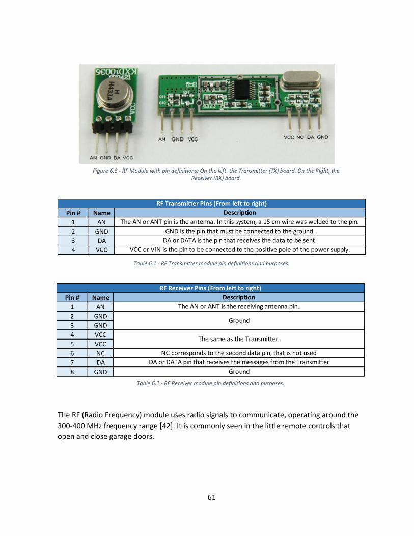
61
The RF (Radio Frequency) module uses radio signals to communicate, operating around the
300-400 MHz frequency range [42]. It is commonly seen in the little remote controls that
open and close garage doors.
Figure 6.6 - RF Module with pin definitions: On the left, the Transmitter (TX) board. On the Right, the Receiver (RX) board.
Pin # Name
1 AN
2 GND
3 DA
4 VCC
RF Transmitter Pins (From left to right)
The AN or ANT pin is the antenna. In this system, a 15 cm wire was welded to the pin.
GND is the pin that must be connected to the ground.
DA or DATA is the pin that receives the data to be sent.
VCC or VIN is the pin to be connected to the positive pole of the power supply.
Description
Table 6.1 - RF Transmitter module pin definitions and purposes.
Pin # Name
1 AN
2 GND
3 GND
4 VCC
5 VCC
6 NC
7 DA
8 GND
NC corresponds to the second data pin, that is not used
DA or DATA pin that receives the messages from the Transmitter
Ground
Description
The AN or ANT is the receiving antenna pin.
Ground
The same as the Transmitter.
RF Receiver Pins (From left to right)
Table 6.2 - RF Receiver module pin definitions and purposes.

62
There are several other technologies, like Bluetooth and Wi-Fi based systems that can
transmit large amounts of data and offer a near perfect connection. But they are also
considerably more expensive (can go up to a 100€ euros against the 10€ of the system used)
but it all depends on what the application requires. RF modules are one of the cheapest
technologies available that are compatible with Arduino, and it is designed to send low data
signals which is ideal for our case where we just have to send signals that command the
receiver board to do something when a specific signal is received. Another advantage is that
the set-up process is relatively simple. It is reported that it can work up to ranges of about
100m depending on the input voltage and the amount of obstacles between the 2 terminals.
On the downside they are quite sensitive to radio noise, and may suffer interferences from
other radio systems close by.
6.2 Computer Connected Part
6.2.1 Interface
The user interface is an application developed using Processing that receives the instructions
of the person controlling the Olfactory Display. The interface uses the keyboard of a
computer, with the assigned keys switching the DC Fan On and Off and alternating between
scents (Table 6.3).
For demonstration purposes, the preliminary application developed has 2 scents options, but
more command options can easily be added.
After the commands being registered by processing they are sent to the Arduino transmitter.
The several options are programed with an if-else statement: to each command pressed, a
specific message is sent to the Transmitter Arduino, in this case in the form of numbers. The
messages are sent using a serial communication, which allows for two computers to send
and receive data to one another. In this case processing by using a library, a list of predefined
commands that can be uploaded when needed, sends data to the Transmitter Arduino
through USB.
Key 1 2 4 5
Command Scent #1 Scent #2 DC Fan On DC Fan Off
Table 6.3 - Interface keys and corresponding commands

63
6.2.2 Transmitter Board
This board, represents the bridge between the user interface and the Olfactory Display. The
board is programmed to read the processing commands, and again through an if-else
statement, sends the appropriate message to the device.
TX Pins
GND
Data
Vin
Antenna
Figure 6.7 - Transmitter board circuit layout with the Pin connections of the TX module.
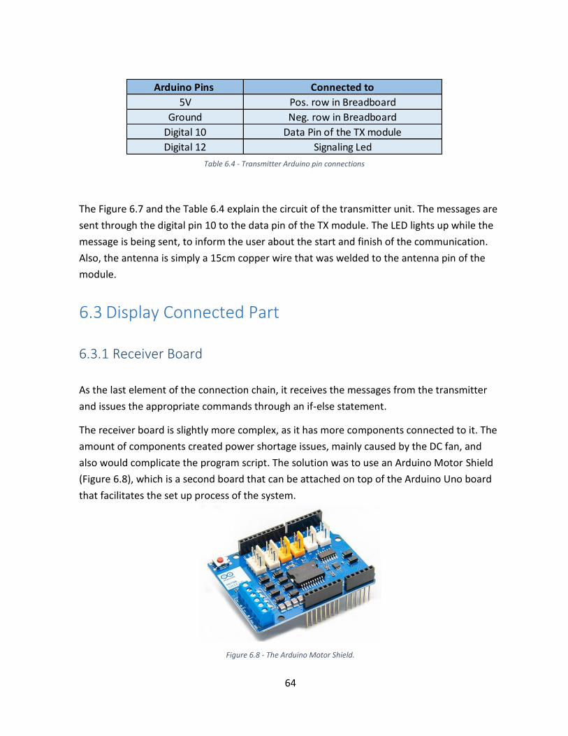
64
The Figure 6.7 and the Table 6.4 explain the circuit of the transmitter unit. The messages are
sent through the digital pin 10 to the data pin of the TX module. The LED lights up while the
message is being sent, to inform the user about the start and finish of the communication.
Also, the antenna is simply a 15cm copper wire that was welded to the antenna pin of the
module.
6.3 Display Connected Part
6.3.1 Receiver Board
As the last element of the connection chain, it receives the messages from the transmitter
and issues the appropriate commands through an if-else statement.
The receiver board is slightly more complex, as it has more components connected to it. The
amount of components created power shortage issues, mainly caused by the DC fan, and
also would complicate the program script. The solution was to use an Arduino Motor Shield
(Figure 6.8), which is a second board that can be attached on top of the Arduino Uno board
that facilitates the set up process of the system.
Figure 6.8 - The Arduino Motor Shield.
Arduino Pins Connected to
5V Pos. row in Breadboard
Ground Neg. row in Breadboard
Digital 10 Data Pin of the TX module
Digital 12 Signaling Led
Table 6.4 - Transmitter Arduino pin connections

65
The Arduino Motor Shield enables us to control several components like DC motors, servos
and many others simultaneously, with dedicated plugs for each type of actuator. In addition,
it has a programing library that largely simplifies the commands allowing for a better control
and a reduced script.
RX Pins GND Data
Pin #2
Data
Pin #1
VCC VCC GND GND Antenna
Figure 6.9 - Receiver board circuit layout. The Pin connections of the RX module are described in the table above.

66
The functioning is very similar to the Transmitter Board. Data is received through pin 11 and
delivered to the servo and DC Fan. Again the LED lights up while messages are being
received. Due to the excessive amount of components, a relatively powerful power supply is
necessary.
Arduino Pins Connected to
5V Pos. row in Breadboard
Ground Neg. row in Breadboard
Digital 4 Signaling Led
Digital 11 Data Pin of the RX module
Out5 Pin Trio Servo
DC Motor Channel A Couple DC Fan
Vin-Ground Power Plug External Power Supply
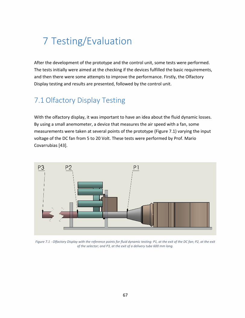
67
Testing/Evaluation
After the development of the prototype and the control unit, some tests were performed.
The tests initially were aimed at the checking if the devices fulfilled the basic requirements,
and then there were some attempts to improve the performance. Firstly, the Olfactory
Display testing and results are presented, followed by the control unit.
7.1 Olfactory Display Testing
With the olfactory display, it was important to have an idea about the fluid dynamic losses.
By using a small anemometer, a device that measures the air speed with a fan, some
measurements were taken at several points of the prototype (Figure 7.1) varying the input
voltage of the DC fan from 5 to 20 Volt. These tests were performed by Prof. Mario
Covarrubias [43].
Figure 7.1 - Olfactory Display with the reference points for fluid dynamic testing: P1, at the exit of the DC fan; P2, at the exit of the selector; and P3, at the exit of a delivery tube 600 mm long.

68
In these first two plots we can immediately see a speed reduction from before and after the
selector, the main cause is the misalignment between the inlet and the selector tubes since
the gap between them is almost nonexistent. Also, there is a considerable difference
between the scented tube and the cleaning tube, which would be expected due to the
presence of the scented cartridges blocking the way.
Figure 7.2 - First 2 plots for measurements taken at the P1 and P2 points.

69
The results taken at the exit of the delivery tube for both clean and scented tube, logically a
greater airflow speed reduction is observed. In the plot bellow, the diameter of the tube is
smaller, so the speed drops even lower due to the increased wall friction on the airflow.
Note that for the initial values of input voltage, the measured value is zero. This is not true,
there is a small amount of airflow reaching the point of measurement in all cases, but the
airflow is not strong enough to counter the inertia of the anemometer fan. This also happens
in the previous set of plots, but it is less evident.
Figure 7.3 - Second couple of plots of measurements taken at P3. Above, with a tube diameter of 10 mm; Bellow, for 5 mm diameter.

70
Lastly, the final plot presents all the results compared to one another. It is clear that the
biggest drop is observed between P1 and P2, suggesting that there is room for improvement
in the interface between the inlet and the selector.
Figure 7.4 - Final plot with all the measurements taken.

71
7.2 Control Unit Testing
7.2.1 Power Tests
The high power drawn by the receiver board requires a stable power supply, so most of the
initial testing was done using a stationary plug-in power supply delivering up to 1.5 amp and
with variable voltage. But the goal is to have a unit that is both portable and wireless, so
batteries would have to be used.
To begin, some tests will be performed to measure the power drawn with the power supply.
After that, some tests are performed with common batteries, to check if they provide
enough power and how long can they last.
Power consumption with the transformer
The voltage and current drawn by the DC motor, the servo motor and RF Receiver module
was measured using a multimeter. Tests were run with 7.5 V and 9 V, the measurements
were taken while the components were in standby (Idle) or being used (Activated).
Table 7.1 - Power Consumption test results.

72
The value of the electrical power (Watt) is given by the multiplication of the current (Amp) by
the voltage (Volt). The values obtained make sense since it is known that DC motors draw
more power when the voltage increases [44].
7.2.2 Battery Life Testing
In this section, the battery life is calculated with a theoretical model and some real tests are
performed to compare. 2 common battery types were tested: One of 9V and 1200 mAh of
capacity, and second one of 4.5V and 6100 mAh.
Battery Life Calculation
In a theoretical approach, the battery longevity was predicted using the equation (7.1)11
[45]. Of course battery life depends on power consumption, which means this depends on
how the Olfactory Display is used. So for this calculation, the data is based on the simulation
performed in the Battery Life Testing section.
𝐵𝑎𝑡𝑡𝑒𝑟𝑦 𝐿𝑖𝑓𝑒 = 𝐵𝑎𝑡𝑡𝑒𝑟𝑦 𝐶𝑎𝑝𝑎𝑐𝑖𝑡𝑦
𝐿𝑜𝑎𝑑 𝐶𝑢𝑟𝑟𝑒𝑛𝑡 ,
(7.1)
𝐿𝑜𝑎𝑑 𝐶𝑢𝑟𝑟𝑒𝑛𝑡 = 𝐶𝑖𝑟𝑐𝑢𝑖𝑡 𝐿𝑜𝑎𝑑 + (𝐴𝑐𝑡𝑖𝑣𝑒 𝐿𝑜𝑎𝑑 ∗ 𝐴𝑐𝑡𝑖𝑣𝑎𝑡𝑖𝑜𝑛 𝑇𝑖𝑚𝑒) ∗ 𝐴𝑉𝐺
AVG - Numerical factor (considered to be 75%) to compensate for the reduction of
drawn power as the battery fades.
Circuit Load - Current drawn while the circuit is on standby
Active Load - Current drawn by the circuit while the device and its electrical
components are being used
Activation time - Ratio between active time and total time, which will be considered a
third of the total.

73
Using the measured load values for each battery (Table 7.2), the expected battery life in
hours is obtained (Table 7.3). As seen from the previous case (Table 7.1), the DC motor is the
component that requires the most power, and it is active for longer periods, while the servo
and the RF module are active for short instants. Nevertheless, during a simulation they have
to be used quite frequently. Logically, the battery life depends on the usage. Either way the
results for battery life make sense: the 4.5 V battery last longer due to its higher capacity and
the fact that with less voltage the DC motor draws less current.
Battery Life Testing
The goal behind the following tests was to see how the system would behave in a one hour
run. During this hour a series of commands were issued and the device’s performance
throughout the period was evaluated.
The test run is a sequence of a few DC motor commands: 10 min off followed by 20 min and
then one repetition. At the same time, every 10 minutes a random sequence of servo
commands was issued.
With the 9v battery, the first 10 minutes with the DC motor off the system worked perfectly.
When the DC Motor was switched off, the servomotor started to fail and shortly after it
Units
Battery Type 4.5 9 Volt
Battery Capacity 6100 1200 mAh
Active Load 350 500 mA
Circuit Load 60 60 mA
AVG N/A
Activation Time N/A
Circuit Current Consumption
0.75
0.333
Units
Battery Type 4.5 9 Volt
Predicted Battery Life 41.38048 6.490872 Hours
Equation Results
Table 7.2 - Current consumption values of the Olfactory Display with the 2 batteries
Table 7.3 - Battery life results using the equation (7.1)

74
stopped reacting to any commands. Apart from that, the DC motor could not be switched off
and when the simulation was restarted, the same thing happened. Clearly the issue was that
DC motor was drawing all the power from the battery, leaving nothing left to operate the
remaining components of the receiver unit. Either way, there was enough power to keep the
DC motor running for the whole hour.
With the 4.5 V battery things started off better. Clearly the DC motor was rotating a lot
slower but the system responded to all the commands, which means there was enough
power for all the components to work simultaneously. However, close to the hour mark the
dc motor control was not working so sharply.
With these battery tests it is obvious that the 4.5 V battery produced better results. The
higher capacity allows it work for longer periods and the reduced voltage avoids the DC
motor from using up all the power. One might think that the good choice would be to go for
low voltage and high capacity batteries but it is not that simple, the DC motor might be
working but it needs more power to provide a satisfactory scent delivery. In addition, using
an efficient DC motor may also improve these results.
Theoretical Vs. Practical Results
The system was not tested to check if the theoretical results were real, it would take 47
hours just to verify the 4.5 v battery test result. The thing is that battery life is not that
relevant in this case, it is how long the system can use all of its capabilities, and with these
batteries this period is not long enough.
7.2.3 Wireless Communication Tests
On this part, the effective range of communication between the RF modules was tested. This
was done by sending a sequence of 20 commands, and check how many are received. Six
test runs were performed, correlating two variables: distance and the presence of obstacles.
The quality of the communication depends of a variety of factors described previously in
section 6.1.3.
Apart from the hardware, another crucial element was the programming of the
communication software. The program algorithm largely depends on the type of information
being sent, that can go from simple high and low commands or full messages. In our case,
because we needed different commands to be recognized, the information is sent in the
form of numbers and letters that can be identified by the receiving module.

75
To send messages, a coding library specifically designed for RF modules is used. A library is a
very helpful file with a series of instructions that are designed to work with a specific
component, like our RF module, and simplify the coding. The libraries influence the speed of
communication, and since commands cannot be sent simultaneously, the responsiveness of
the communication becomes more important. In this system, two different libraries were
tested:
RCSwitch [46] - This library is commonly used on small radio remotes that control
garage doors. The programming is a little simpler than Virtualwire but on the
downside the communication is slow, it took 4 seconds to process each command.
VirtualWire [47] - Designed specifically for Arduino, the VirtualWire library showed an
increased responsiveness compared to the RCSwitch. The script is a bit longer, but it
allowed for a command to be processed under 1 second. It was immediately clear
that this was the library to be used.
The tests were communication effectiveness tests were performed indoors. A random
sequence of 20 commands was tested at 3 different distances. In one case, there was a clear
line of sight between the transmitter and receiver modules, in the other, there were
obstacles in between such as pieces of furniture or walls.
The results are the percentage of commands that were correctly received by the receiver
module. When the distance is increased, some commands do not pass and sometimes a
single command can take a bit longer to be processed. The transmitter module is powered by
a USB cable, which provides 5V to the transmitter module. If necessary, effective range can
be increased with the input voltage.
3 9 12
Yes 100% 100% 95%
No 100% 95% 95%
Distance (m)
Obstacles
Communication
Effectiveness
Table 7.4 - Communication distance test results

76

77
Conclusion and Future Research
In a field that is plenty with innovative but complex solutions, an economic, simple and
reliable Olfactory Display prototype and a wireless control unit were developed that can be
adapted for several applications.
More concretely, with the Olfactory Display there are some achievements to be pointed out.
The OIKOS SFR methodology was successfully integrated, and proved to be highly adapt to
the type of device presented. Not only it worked, the OIKOS scents had the advantage of not
adhering to the device, a problem that most developers are faced with. In addition, the scent
generation, selection and delivery functions were correctly integrated fulfilling their
respective performance requirements without compromising the design’s simplicity.
The control unit developed also met its requirements. The wireless transmission of data was
accomplished using the RF modules that although cheap, provided a reliable and quick
communication within the distances usually required for these applications. In addition, a
simple user-interface was successfully integrated within the wireless communication
process.
There is plenty of room for improvement on both parts. This Olfactory Display prototype
served to test a specific design type, to use it as a final product there it has to be adapted to
a specific application. For starters, a wearable component is needed to direct the delivery
tube to the user’s nose. Fluid dynamic losses were another key aspect with this design, this
could be further improved by improving the tube transitions. In addition, extra scented tubes
could be added to the revolver selector and the limited range of 180° degrees could be
doubled with a set of gears. This way, the range of scents would be increased without using
extra room. Another way to increase the scent range would be to add another selector after
the first one, although one would have to be careful with this approach to avoid any
additional fluid dynamic losses.
With the control unit, power was the main issue that could be improved. There was no such
problem with a plug in power supply but since the prototype is meant to be wearable, the
receiver module has to be compatible with a battery or any other portable power supply. A
more efficient DC motor would mitigate this effect. Nevertheless, a powerful portable power
supply will always be necessary.

78

79
References
[1] W. Powers, "The Science of Smell Part 1: Odor perception and physiological," Iowa
State University, University Extension, 2004.
[2] T. Nakamoto, Human Olfactory Displays and Interfaces: Odor Sensing and Presentation,
Tokyo: Tokyo Institute of Technology, Japan, 2012.
[3] Water Environment Federation, "Odor Control for Wastewater Facilities. Manual of
Practice No. 22.," Water Pollution Control Federation, Washington D.C., 1978.
[4] J. Morrison, "The sense of smell - Definitions and Structural components required,"
HumanPhysiology.academy, 2014 - 2015. [Online]. Available:
http://humanphysiology.academy/Smell/Smell.html. [Accessed 05 06 2015].
[5] L. Pavesi, Graduation Thesis - Design Olfactivo: progettare con gli odori, Milan: Scuola
del Design - Politecnico di Milano, 2012.
[6] Zara, "Green Herbs Air Freshener Sticks," [Online]. Available:
http://www.zarahome.com/tr/en/fragrance/green-herbs-c1293864p5949627.html.
[Accessed 15 June 2015].
[7] D. W. Kim, K. Nishimoto, S. Kunifuki, Y. Kawakami and H. Ando, "Development of
Aroma-Card Based Soundless Olfactory Display," in Proceeding of 16th IEEE
International Conference on Electronics, Circuits and Systems (ICECS), 2009.
[8] T. Yamada, S. Yokoyama, T. Tanikawa, K. Hirota and M. Hirose, "Wearable Olfactory
Display: Using Odor in Outdoor Environment," in Proceedings of IEEE Virtual Reality
Conference, Alexandria, Virginia, 2006.
[9] A. Kadowaki, J. Sato, Y. Bannai and K.-i. Okada, "Presentation Technique of Scent to
Avoid Olfactory Adaptation," in Proceedings of 17th International Conference on
Artificial Reality and Telexistence, 2007.

80
[10] Fisitech, "A Great Instrument To Atomize Liquid: Ultrasonic Vibrator," 4 March 2011.
[Online]. Available: http://subato.blogspot.it/2011/03/great-instrument-to-atomize-
liquid.html. [Accessed 9 June 2015].
[11] J. Yu, Y. Yanagida, S. Kawato and N. Tetsutani, "Air Cannon Design for Projection-Based
Olfactory Display," in 13th International Conference on Artificial Reality and
Telexistence, Tokyo, 2003.
[12] J. Kaye, Symbolic Olfactory Display, Cambridge, MA: Master Thesis, Massachussets
Institute of Technology, 2001.
[13] C. A. Wisneski, The Design of Personal Ambient Displays, Cambridge, MA: Master
Thesis, Massachusetts Institute of Technology, 1999.
[14] S. Ren, Ambient Displays: Information Visualization through Physical Interfaces.,
Cambridge, MA: Master Thesis, Massachusetts Institute of Technology, 2000.
[15] Wikipedia, "iSmell," 7 November 2013. [Online]. Available:
https://en.wikipedia.org/wiki/ISmell. [Accessed 23 June 2015].
[16] S. Bromley, "Games User Research," 29 January 2010. [Online]. Available:
http://www.stevebromley.com/blog/2010/01/29/no-user-testing-oops-%E2%80%93-
the-digiscent-ismell/. [Accessed 23 June 2015].
[17] J. F. Morie, The Scent Collar, Marina Del Rey, California: Institute for Creative
Technologies, USC, 2003.
[18] C. J. Watkins, "Methods and apparatus for localized delivery of scented aerosols".
United States of America Patent US6536746 B2, 25 March 2003.
[19] Y. Yanagida, H. Noma, N. Tetsutani and A. Tomono, "An Unencumbering, Localizd
Olfactory Display," in CHI 2003: New Horizons, Fort Lauderdale, Florida, 2003.
[20] S. Kawato and N. Tetsutani, "Real-time Detection of Between-the-Eyes with a Circle
Frequency Filter.," in 5th Asian Conference on Computer Vision, Melbourne, 2002.
[21] Y. Yanagida, S. Kawato, H. Noma, A. Tomono and N. Tetsutani, "Projection-Based
Olfactory Display with Nose Tracking," in IEEE Virtual Reality 2004 March 27-31,
Chicago, 2004.

81
[22] F. Nakaizumi, Y. Yanagida, H. Noma and H. Kenichi, "SpotScents: A Novel Method of
Natural Scent Delivery Using Multiple Scent Projectors," in IEEE Virtual Reality,
Alexandria, Virginia, 2006.
[23] K. Murai, T. Serizawa and Y. Yanagida, "Localized Scent Presentation to a Walking
Person by Using Scent Projectors," in IEEE International Symposium on Virtual Reality
Innovation, Singapore, 2011.
[24] T. S. Lorig, D. G. Elmes, D. H. Zald and J. V. Pardo, "A computer-controlled olfactometer
for fMRI and electrophysiological studies of olfaction.," Behavior Research Methods,
Instruments, & Computers, pp. 370 - 375, 1999.
[25] A. Mochizuki, T. Amada, S. Sawa, T. Takeda, S. Motoyashiki, K. Kohyama, M. Imura and
K. Chihara, "Fragra: A Visual-Olfactory VR Game," in SIGGRAPH , Los Angeles, California,
2004.
[26] J. P. Cater, "The Nose Have It!," Letters to the Editor, Presence, vol. 1, no. 4, pp. 493-
494, 1992.
[27] J. P. Cater, personal e-mail, 5, Inc., and US Air Force Fire Research group, Tyndall AFB,
1999.
[28] OIKOS Fragrances, "Tecnologia," OIKOS Fragrances, 2005. [Online]. Available:
http://www.oikosfragrances.com/tecnologia.htm. [Accessed 29 June 2015].
[29] T. Nakamoto, S. Otaguro, M. Kinoshita, M. Nagahama, K. Ohinishi and T. Ishida,
"Cooking Up an Interactive Olfactory Game Display," Computer Graphics and
Applications, IEEE, vol. 28, no. 1, pp. 75 - 78, 2008.
[30] Wikipedia, "Aromatherapy," 13 July 2015. [Online]. Available:
https://en.wikipedia.org/wiki/Aromatherapy. [Accessed 14 July 2015].
[31] S. A. Brewster, D. K. McGookin and C. A. Miller, "Olfoto: Designing a Smell-Based
Interaction," in CHI, Montreal, Canada, 2006.
[32] M. Dirjish, "What’s The Difference Between Brush DC And Brushless DC Motors?,"
Electronic Design, 16 February 2012. [Online]. Available:
http://electronicdesign.com/electromechanical/what-s-difference-between-brush-dc-
and-brushless-dc-motors. [Accessed 7 July 2015].

82
[33] OIKOS Fragrances, OIKOS Scent Rectangles Brochure, Milano, 2014.
[34] OIKOS Fragrances, OIKOS Cube3 Brochure, Milano, 2012.
[35] G. Steinhardt, C. Schoon, Extension Soil Conservation Education Specialists and J.
Wilcox, "Wind Erosion Concerns in Indiana," Purdue University Corporate Extension
Service, [Online]. Available: https://www.extension.purdue.edu/extmedia/AY/AY-
271.html. [Accessed 30 June 2015].
[36] Wikipedia, "Servomotor," 16 May 2015. [Online]. Available:
https://en.wikipedia.org/wiki/Servomotor. [Accessed 30 June 2015].
[37] D. Sawicz, "Hobby Servo Fundamentals," [Online]. Available:
http://www.princeton.edu/~mae412/TEXT/NTRAK2002/292-302.pdf. [Accessed 30
June 2015].
[38] B. Fry and C. Reas, "Processing Software Homepage," Processing, [Online]. Available:
https://processing.org/. [Accessed 29 06 2015].
[39] Arduino, "Arduino Home," [Online]. Available: https://www.arduino.cc/. [Accessed 29
June 2015].
[40] Wikipedia, "Arduino," 30 June 2015. [Online]. Available:
https://en.wikipedia.org/wiki/Arduino. [Accessed 1 July 2015].
[41] Wikipedia, "Processing," 31 May 2015. [Online]. Available:
https://en.wikipedia.org/wiki/Processing_(programming_language). [Accessed 1 July
2015].
[42] M. Schwartz, "Open Home Automation," 7 January 2014. [Online]. Available:
https://www.openhomeautomation.net/wireless-home-automation/. [Accessed 1 July
2015].
[43] M. Covarrubias, P. Fernandes, M. Bordegoni, U. Cugini, E. Maggioni and A. Gallace,
"Wearable Multi-Fragrance Olfactory Display for VR/AR Applications.," KAEMART
Research Group at the Politecnico Di Milano, Milan, 2016.
[44] F. Braghin, "Control And Actuating Devices Lecture Notes," Politecnico Di Milano,
Milan, 2014.

83
[45] Jenesis International, "How is Battery Life Calculated," [Online]. Available:
http://jenesisproducts.com/how-is-battery-life-calculated/. [Accessed 07 July 2015].
[46] 03 November 2013. [Online]. Available: https://github.com/sui77/rc-switch. [Accessed
06 July 2015].
[47] M. McCauley, VirtualWIre, 2013.
[48] A. Gilbert, What the nose knows: The science of scent in everyday life, New York:
Crown Publishing, 2008.
[49] "How Internet Odors Will Work," How Stuff Works.com, 05 January 2001. [Online].
Available: http://computer.howstuffworks.com/internet-odor1.htm. [Accessed 2015
June 13].

84

85
Appendix A
In this the section, the code for the interface application with the software Processing is
presented:
1. import processing.serial.*; 2. 3. Serial myPort; // Create object from Serial class 4. 5. void setup() 6. { 7. String portName = Serial.list()[0]; 8. myPort = new Serial(this, portName, 9600); 9. } 10. 11. void draw() { 12. if (keyPressed){ 13. if(key=='1'||key=='1'){ 14. fill(0); //blck 15. myPort.write (49); 16. delay (10); 17. } 18. 19. if(key=='2'||key=='2'){ 20. fill(1); //blck 21. myPort.write (50); 22. delay (10); 23. } 24. 25. if(key=='3'||key=='3'){ 26. fill(2); //blck 27. myPort.write (51); 28. delay (10); 29. } 30. 31. if(key=='4'||key=='4'){ 32. fill(3); //blck 33. myPort.write (52); 34. delay (10); 35. } 36. 37. if(key=='5'||key=='5'){ 38. fill(4); //blck 39. myPort.write (53); 40. delay (10); 41. } 42. 43. }else { 44. fill(255); //white 45. } 46. rect (25, 25, 50, 50); 47. } 48.

86
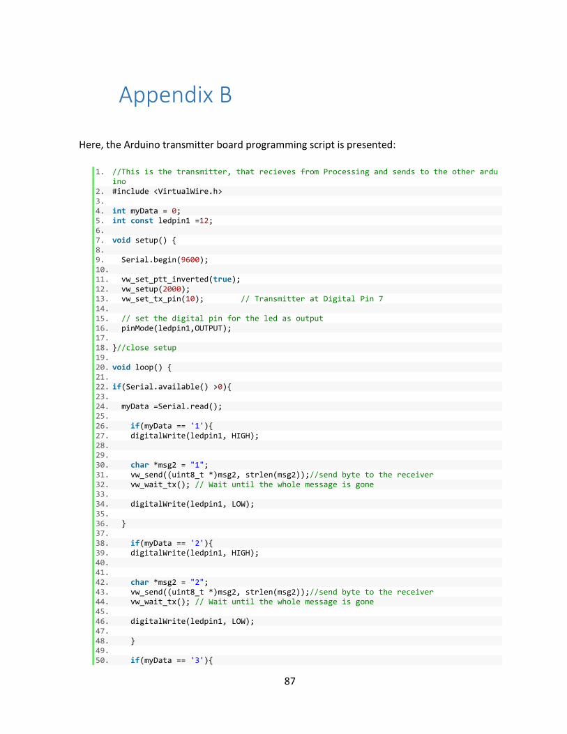
87
Appendix B
Here, the Arduino transmitter board programming script is presented:
1. //This is the transmitter, that recieves from Processing and sends to the other arduino
2. #include <VirtualWire.h> 3. 4. int myData = 0; 5. int const ledpin1 =12; 6. 7. void setup() { 8. 9. Serial.begin(9600); 10. 11. vw_set_ptt_inverted(true); 12. vw_setup(2000); 13. vw_set_tx_pin(10); // Transmitter at Digital Pin 7 14. 15. // set the digital pin for the led as output 16. pinMode(ledpin1,OUTPUT); 17. 18. }//close setup 19. 20. void loop() { 21. 22. if(Serial.available() >0){ 23. 24. myData =Serial.read(); 25. 26. if(myData == '1'){ 27. digitalWrite(ledpin1, HIGH); 28. 29. 30. char *msg2 = "1"; 31. vw_send((uint8_t *)msg2, strlen(msg2));//send byte to the receiver 32. vw_wait_tx(); // Wait until the whole message is gone 33. 34. digitalWrite(ledpin1, LOW); 35. 36. } 37. 38. if(myData == '2'){ 39. digitalWrite(ledpin1, HIGH); 40. 41. 42. char *msg2 = "2"; 43. vw_send((uint8_t *)msg2, strlen(msg2));//send byte to the receiver 44. vw_wait_tx(); // Wait until the whole message is gone 45. 46. digitalWrite(ledpin1, LOW); 47. 48. } 49. 50. if(myData == '3'){

88
51. digitalWrite(ledpin1, HIGH); 52. 53. 54. char *msg2 = "3"; 55. vw_send((uint8_t *)msg2, strlen(msg2));//send byte to the receiver 56. vw_wait_tx(); // Wait until the whole message is gone 57. 58. digitalWrite(ledpin1, LOW); 59. 60. } 61. 62. if(myData == '4'){ 63. digitalWrite(ledpin1, HIGH); 64. 65. 66. char *msg2 = "4"; 67. vw_send((uint8_t *)msg2, strlen(msg2));//send byte to the receiver 68. vw_wait_tx(); // Wait until the whole message is gone 69. 70. digitalWrite(ledpin1, LOW); 71. 72. 73. } 74. 75. if(myData == '5'){ 76. digitalWrite(ledpin1, HIGH); 77. 78. 79. char *msg2 = "5"; 80. vw_send((uint8_t *)msg2, strlen(msg2));//send byte to the receiver 81. vw_wait_tx(); // Wait until the whole message is gone 82. 83. digitalWrite(ledpin1, LOW); 84. 85. } 86. } 87. }

89
Appendix C
Lastly, the code for the Arduino Receiver board is presented:
1. // RECIEVER CODE 2. // 3. //Serial port COM6, the second one after the phone jack. 4. // 5. //Servo library doesnt work, so SerrvoTimer2 is used. With this library only ms work
with the write () 6. //command. Values of ms range from 544 to 2400 7. // 8. //DC Motor commands do not work but servo does. I did not understand the reason yet.
Maybe theres a conflict 9. //between the libraries. 10. // 11. //DC MOTOR CONTROL 12. //Using the Motor Shield, the pins will be as follow 13. // 14. //Function Channel A Channel B 15. //Direction Digital 12 Digital 13 16. //Speed (PWM) Digital 3 Digital 11 17. //Brake Digital 9 Digital 8 18. //Current Sensing Analog 0 Analog 1 19. 20. 21. #include <VirtualWire.h> 22. #include <ServoTimer2.h> 23. 24. ServoTimer2 servoMain; // Define our Servo 25. 26. int const ledpin4 =4; 27. 28. void setup() 29. { 30. 31. //SERVO SETUP 32. servoMain.attach(5); // servo on digital pin 5 33. 34. //DC MOTOR SETUP on Channel A 35. 36. pinMode(12, OUTPUT); //Initiates Motor Channel A pin 37. pinMode(9, OUTPUT); //Initiates Brake Channel A pin 38. 39. pinMode (ledpin4,OUTPUT); 40. 41. vw_set_ptt_inverted(true); 42. vw_setup(2000); // Bits per sec 43. vw_set_rx_pin(11);//Receiver at Digital Pin 11 44. 45. vw_rx_start();// Start the receiver PLL running 46. 47. 48. 49.
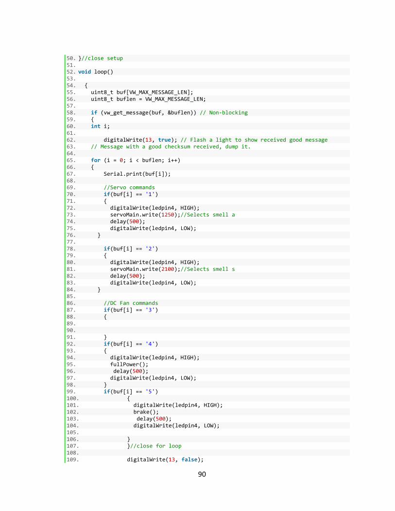
90
50. }//close setup 51. 52. void loop() 53. 54. { 55. uint8_t buf[VW_MAX_MESSAGE_LEN]; 56. uint8_t buflen = VW_MAX_MESSAGE_LEN; 57. 58. if (vw_get_message(buf, &buflen)) // Non-blocking 59. { 60. int i; 61. 62. digitalWrite(13, true); // Flash a light to show received good message 63. // Message with a good checksum received, dump it. 64. 65. for (i = 0; i < buflen; i++) 66. { 67. Serial.print(buf[i]); 68. 69. //Servo commands 70. if(buf[i] == '1') 71. { 72. digitalWrite(ledpin4, HIGH); 73. servoMain.write(1250);//Selects smell a 74. delay(500); 75. digitalWrite(ledpin4, LOW); 76. } 77. 78. if(buf[i] == '2') 79. { 80. digitalWrite(ledpin4, HIGH); 81. servoMain.write(2100);//Selects smell s 82. delay(500); 83. digitalWrite(ledpin4, LOW); 84. } 85. 86. //DC Fan commands 87. if(buf[i] == '3') 88. { 89. 90. 91. } 92. if(buf[i] == '4') 93. { 94. digitalWrite(ledpin4, HIGH); 95. fullPower(); 96. delay(500); 97. digitalWrite(ledpin4, LOW); 98. } 99. if(buf[i] == '5') 100. { 101. digitalWrite(ledpin4, HIGH); 102. brake(); 103. delay(500); 104. digitalWrite(ledpin4, LOW); 105. 106. } 107. }//close for loop 108. 109. digitalWrite(13, false);

91
110. 111. }//close main if 112. }//close loop 113. //you can print the data entered when debugging by adding Serial.println 114. 115. /////////////////////////////////////////////////////////////////////////////
/////////// 116. 117. void fullPower() 118. { 119. 120. digitalWrite(12, HIGH); //Establishes BackWard direction of Channel A 121. digitalWrite(9, LOW); //Disengage the Brake for Channel A 122. analogWrite(3, 255); //Spins the motor on Channel A at Full power 123. } 124. 125. void brake() 126. { 127. digitalWrite(9, HIGH); //Engages the Brake for Channel A 128. analogWrite(3, 0); 129. } 130. //End Of Code