Pneumatics - Use
69
Pneumatics - Use Some examples of everyday pneumatic systems are shown below. How many do you recognise?
description
Pneumatics - Use. Some examples of everyday pneumatic systems are shown below. How many do you recognise?. Pneumatics - Use. Pneumatics are also used a lot in industry. It can be used to do lots of different jobs such as moving, holding or shaping objects. Advantages of Pneumatics. - PowerPoint PPT Presentation
Transcript of Pneumatics - Use

Pneumatics - Use
Some examples of everyday pneumatic systems are shown below. How many do you recognise?

Pneumatics - Use
Pneumatics are also used a lot in industry. It can be used to do lots of different jobs such as moving, holding or shaping objects.
MOVE HOLD
FORM PROCESS

Advantages of Pneumatics
Clean: Pneumatic systems are clean because they use compressed air. If a pneumatic system develops a leak, it will be air that escapes and not oil. This air will not drip or cause a mess which makes pneumatics suitable for food production lines.
Safe: Pneumatic systems are very safe compared to other systems. We cannot, for example, use electronics for paint spraying because many electronic components produce sparks and this could cause the paint to catch fire.

Advantages of Pneumatics
Reliable: Pneumatic systems are very reliable and can keep working for a long time. Many companies invest in pneumatics because they know they will not have a lot of breakdowns and that the equipment will last for a long time.
Economical: If we compare pneumatic systems to other systems, we find that they are cheaper to run. This is because the components last for a long time and because we are using compressed air.
Advantages of Pneumatics
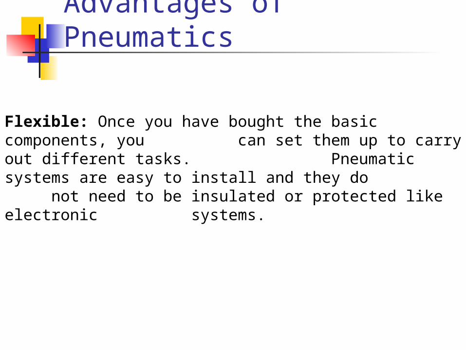
Flexible: Once you have bought the basic components, you can set them up to carry out different tasks.
Pneumatic systems are easy to install and they do not need to be insulated or protected like electronic systems.
Pupil Assignment
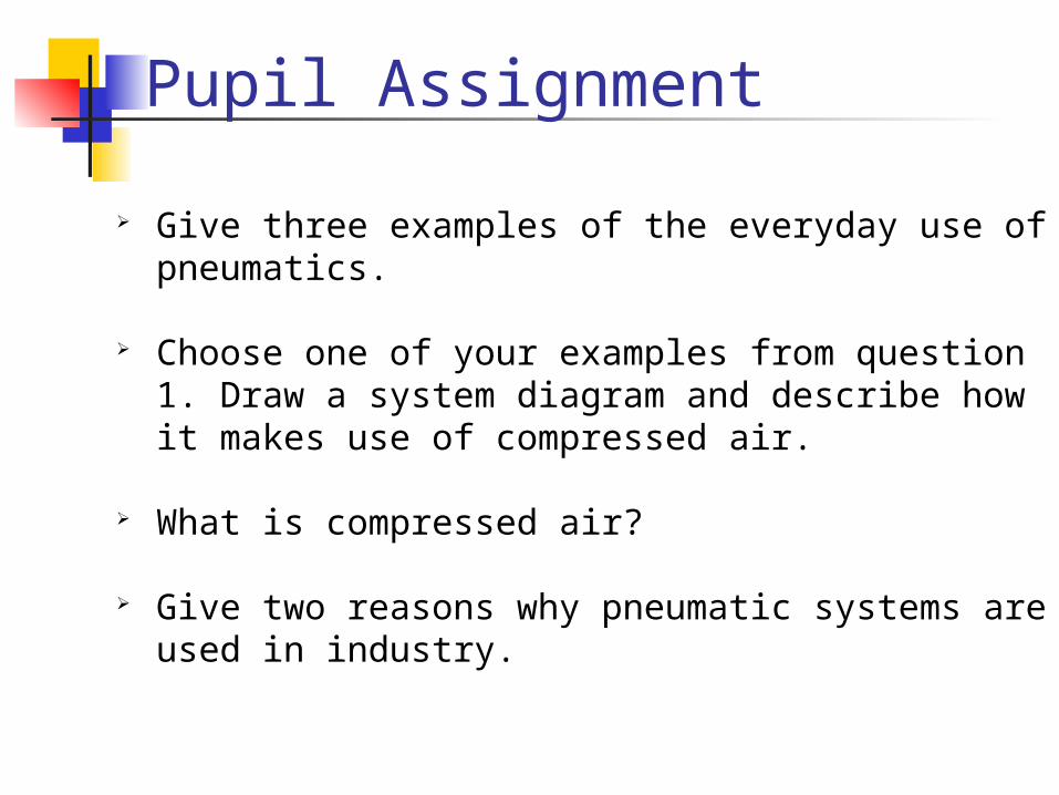
Give three examples of the everyday use of pneumatics.
Choose one of your examples from question 1. Draw a system diagram and describe how it makes use of compressed air.
What is compressed air?
Give two reasons why pneumatic systems are used in industry.

Safety Rules
Never blow compressed air at anyone, not even yourself.
Never let compressed air come into contact with your skin, as this can be very dangerous.
Always wear safety goggles when you are connecting and operating circuits.
Check that all airlines are connected before turning on the main air supply.

Safety Rules
Always turn off the main air supply before changing a circuit.
Keep your hands away from moving parts.
Avoid having airlines trailing across the floor or where someone could trip or become entangled.

The Compressor
In order to supply pneumatic systems with compressed air we use a machine called a compressor. A pump that is driven by a motor, sucks in air from the room and stores it in a tank called the receiver. You will be able to hear the compressor when it is running. Sometimes though, it will stop because the receiver is full.

The Manifold
ON
OFF
Not everyone in your class could connect directly to the compressor, as this is not practical. Instead, a pipe takes the compressed air from the receiver to various points around the room. We would normally connect a device called a manifold to these points. The manifold lets us connect lots of components to the compressed air. It also lets us switch our circuits on and off.

Pupil Assignment
What machine is used to compress the air?
How does this machine work?
Why does it stop occasionally?
What is the purpose of a manifold?
Why is it important to follow the safety rules when using pneumatics?

Components - Cylinders
Single-acting cylinder
Cylinders are the components which move, hold, shape or process work in pneumatics.
A single-acting cylinder requires only one air supply. If we supply compressed air to a single-acting cylinder, the air pushes against the piston inside the cylinder and causes it to outstroke. When the piston has fully outstroked it is said to be positive.
positive
Air in

Components - Cylinders
If we stop the supply of air then the spring inside the cylinder causes the piston to instroke to its starting position and the piston is said to be negative. As this happens, the air inside the cylinder is pushed back out.
negative
Air out

Components – SAC
PORT
PISTON
PISTON ROD
SPRING
Piston Out = +ve or outstrokedPiston In = -ve or instroked

Components - Valves
Cylinders need additional components, known as valves, to operate. The simplest valve we use is the 3/2 valve shown opposite.
It is known as a 3/2 because it has 3 ports and has 2 operating positions, on and off.

Components – 3/2 Valves
Main Air (Port 1) Symbol
Exhaust Symbol
(Port 3)
Port 2 Connects to subsequent components
Actuator (In this case a PUSH BUTTON)
Pupil Activity
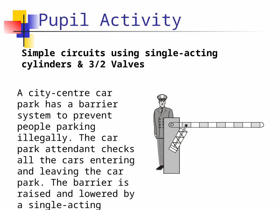
A city-centre car park has a barrier system to prevent people parking illegally. The car park attendant checks all the cars entering and leaving the car park. The barrier is raised and lowered by a single-acting cylinder. The attendant pushes a button to operate the system.
Simple circuits using single-acting cylinders & 3/2 Valves

Pupil Activity
3/2 ValvePressbutton
Barrierraises
Cylinder
Systems Diagram
1) Copy down the systems and circuit diagrams into your note book.
2) Collect the necessary components and pipe.
3) Connect up the components as shown, (Make sure you connect to the correct ports).
4) Connect main air to the circuit and push the button.

Circuit Operation
When the button is pressed, the valve changes state and supplies air to the single-acting cylinder. This causes the piston to outstroke.
When the button is released, the valve returns to its original state and the piston is able to instroke, (spring returns piston rod), ready for the process to begin again.

ACTUATORS
PLUNGER
PUSHBUTTON
LEVER
ROLLER
ROLLERTRIP
SOLENOID
PILOT AIR
DIAPHRAGM
SPRING
FOOTPEDAL
Double Acting Cylinder
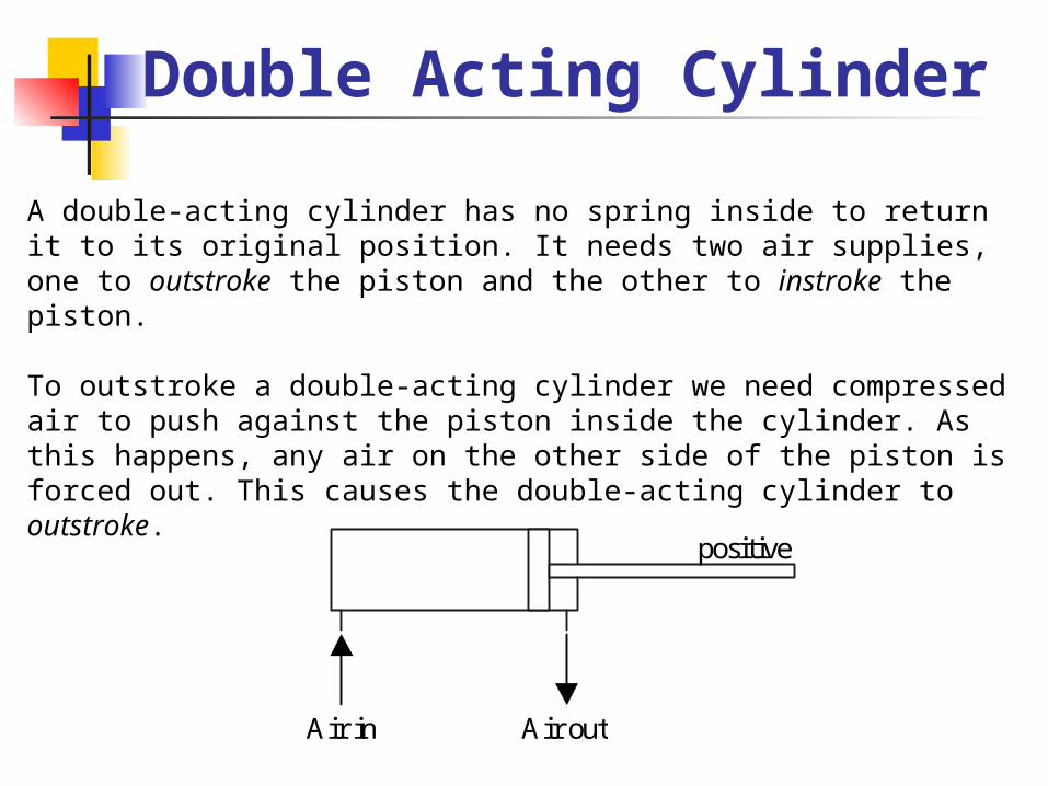
A double-acting cylinder has no spring inside to return it to its original position. It needs two air supplies, one to outstroke the piston and the other to instroke the piston.
To outstroke a double-acting cylinder we need compressed air to push against the piston inside the cylinder. As this happens, any air on the other side of the piston is forced out. This causes the double-acting cylinder to outstroke.
positive
Air in Air out
Double Acting Cylinder
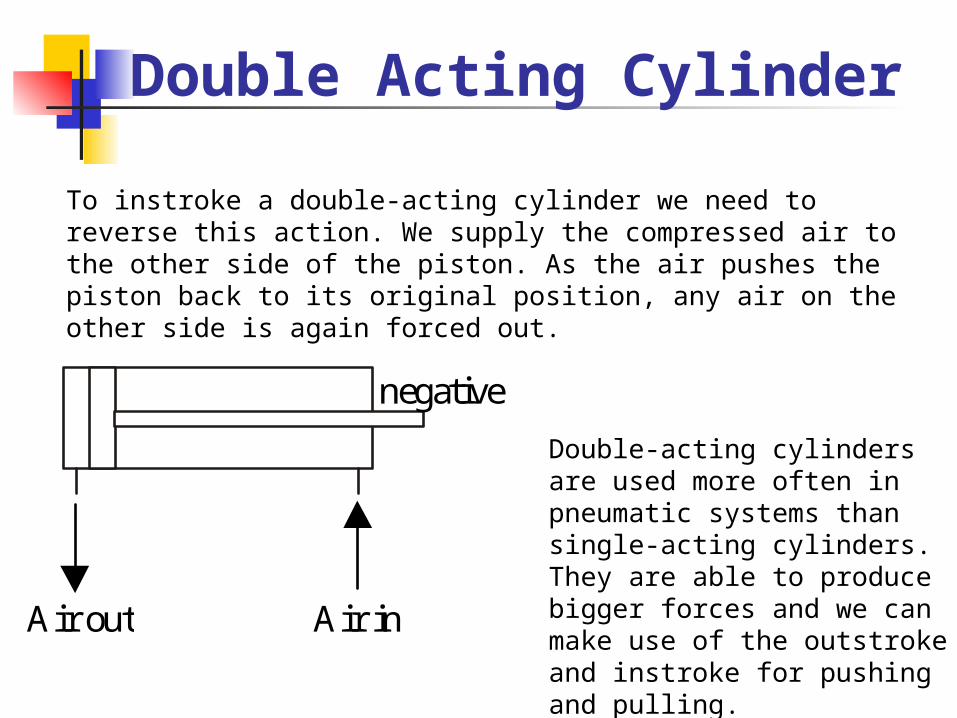
To instroke a double-acting cylinder we need to reverse this action. We supply the compressed air to the other side of the piston. As the air pushes the piston back to its original position, any air on the other side is again forced out.
negative
Air inAir out
Double-acting cylinders are used more often in pneumatic systems than single-acting cylinders. They are able to produce bigger forces and we can make use of the outstroke and instroke for pushing and pulling.
Pupil Activity
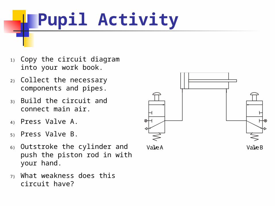
Valve A Valve B
1) Copy the circuit diagram into your work book.
2) Collect the necessary components and pipes.
3) Build the circuit and connect main air.
4) Press Valve A.
5) Press Valve B.
6) Outstroke the cylinder and push the piston rod in with your hand.
7) What weakness does this circuit have?

Circuit Problems
There are many problems when controlling a double-acting cylinder with two 3/2 valves. You should have discovered from the last circuit that it is easy to push or pull the piston. This is because you do not have a constant supply of air to keep the piston in place. When you actuate the 3/2 valve, it outstrokes the piston. When the 3/2 valve is not actuated, air is free to escape or exhaust back through the valve. This means that any force or effort placed on the piston will make it move easily.
A further disadvantage is that the 3/2 valve needs to be actuated until the double-acting cylinder has fully outstroked or instroked. Releasing the valve before the stroke is complete will mean the piston will stop short of its final position.

5/2 Valves
Port 1 Main AirPort 5 Exhaust
Port 3 Exhaust
Port 2 Connects to other components
Port 4 Connects to other components
Actuator will depend on valve use. In this case it is a 5/2 Pilot Pilot operated valve.

Pupil Activity
Valve A
1) Copy the circuit into your work book.
2) Build the circuit and connect main air.
3) Actuate valve A.
4) Try to push the piston rod in.
5) Actuate valve B.
6) Describe in your own words what is happening.
IMPORTANT: PILOT AIR
Valve B

PUPIL ASSIGNMENT
A
B
C
A door entry system is controlled by pneumatics. The system makes use of a double-acting cylinder. Part of the circuit diagram is Shown.
1) Name each of the components A, B and C.
1) Complete the diagram so that the door will open and close.
2) Describe how the circuit operates.

The T Piece
AIR OUT
AIR IN
AIR OUT
T-piece
A T-piece or T-connector is a very simple component that lets us split or divide airflow. It can be very useful if you want two cylinders to operate at the same time.

Pupil Activity
A delivery lorry uses a pneumatic braking system. The brakes operate when the driver presses the foot brake. Two single-acting cylinders should outstroke at the same time and press against the wheels.
Design, build and test a circuit which will meet the requirements of the lorry braking system. (You can use a push button, spring return 3/2 valve instead of a foot pedal.)
Explain the purpose of the T-piece.

Simulation Software
It is often useful to simulate a pneumatic circuit prior to building it. This can save costly mistakes and is much quicker than physically building a pneumatic circuit.
Start the computer program AIRWAYS
Click on the START icon
Select Unit 2 Single Acting Cylinder and 3 Port Valves
Your teacher will now show you how to connect up the components

Flow Control Valves Bi-Directional
You should have noticed in the circuits you have built so far that the pistons move very quickly. Sometimes this can be dangerous or it may prevent the circuit from working properly. To slow down the speed of a piston we use a flow control valve.
There are 2 types of Flow Control Restrictor, the 1st is the BI-DIRECTIONAL or THROTTLE Restrictor. The symbol is shown opposite.

Flow Control Valves
The problem with this type of restrictor is that it always slows down the speed of the piston in both directions. In many cases, we would only want either the outstroke or the instroke to be slowed down.
Also, if we study the piston movement very carefully, we sometimes find that it is quite jerky not smooth as we would want it to be.
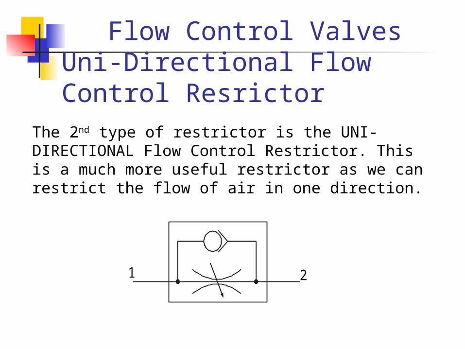
Flow Control Valves Uni-Directional Flow Control Resrictor
The 2nd type of restrictor is the UNI-DIRECTIONAL Flow Control Restrictor. This is a much more useful restrictor as we can restrict the flow of air in one direction.
1 2
Flow Control Valves Uni-Directional
1 2
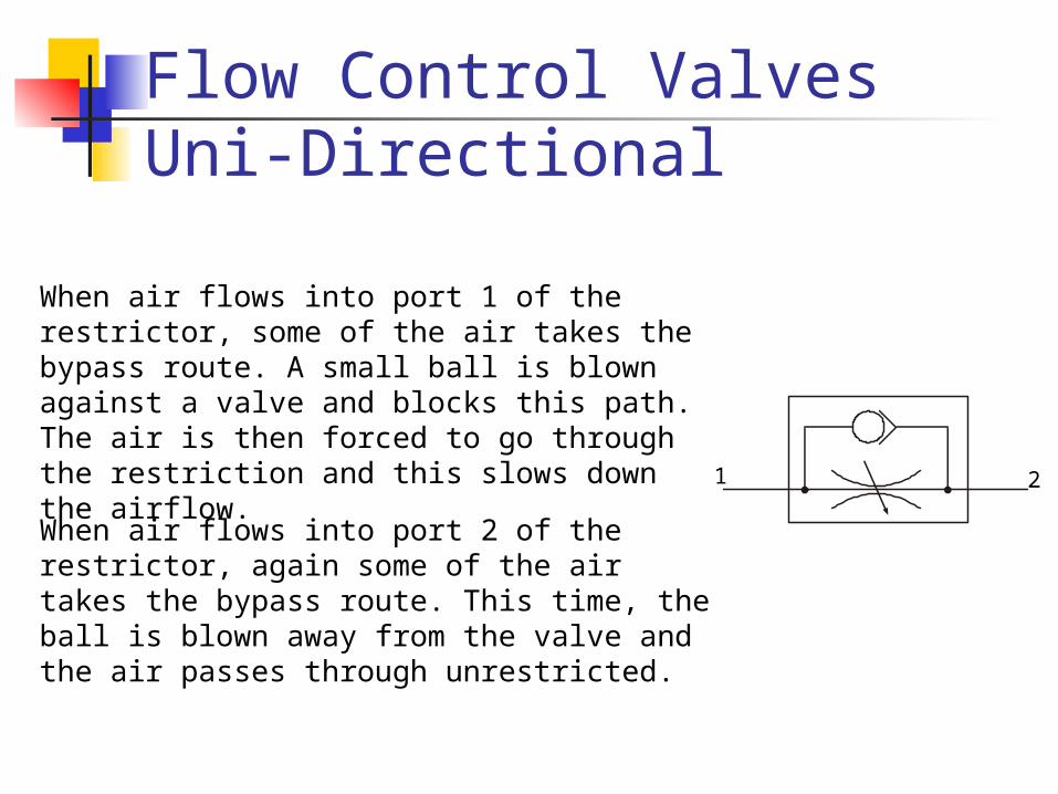
When air flows into port 1 of the restrictor, some of the air takes the bypass route. A small ball is blown against a valve and blocks this path. The air is then forced to go through the restriction and this slows down the airflow.
When air flows into port 2 of the restrictor, again some of the air takes the bypass route. This time, the ball is blown away from the valve and the air passes through unrestricted.

Pupil Activity
Valve A Valve B
1) Copy the circuit into your workbook
2) Collect the necessary components and pipes
3) Build and test the circuit
4) In your own words, describe the operation of the circuit

Circuit Operation
The restrictor is placed so that it slows down the exhaust air coming from the cylinder. When valve A is pressed, the 5/2 valve changes state and starts to supply the cylinder with air to make it outstroke.Air trapped on the other side of the piston escapes through the restrictor slowly. This makes the piston outstroke slowly.
We always restrict the exhaust air coming from a cylinder as this makes the piston move much more smoothly.

Pupil Activity
For safety reasons, the entrance door to a storeroom in a supermarket must open and close slowly. A double-acting cylinder is used to slide the door.
Valve A Valve B
An incomplete circuit is shown. Complete the circuit diagram then build and test the circuit.
Describe the operation of the circuit.

Pupil Activity
Part of a manufacturing process involves dipping components into a chemical solution to prepare them before they are painted.
A double-acting cylinder controls the process and for safety reasons the cylinder must outstroke and instroke slowly.
Using Airways computer simulation program, design a circuit that would solve this problem.
Why is it important that the cylinder operates slowly?

AND Control
Although pneumatic circuits are very safe, it is important to take safety precautions. AND control circuits can be used to help prevent accidents by ensuring that guards are in position before machines are switched on. These circuits can also be used to stop a machine being switched on accidentally or to stop operators placing their hands in the machine when it is running.
SLIDINGDOOR
VALVEPOSITION

Pupil Activity – AND Control
Valve A Valve B
1) Copy down the circuit into your workbook
2) Build and test the circuit
3) Describe the operation of the circuit
4) The operation of the cylinder can be described by a TRUTH TABLE
VALVE A
OFF
ON
OFF
ON
VALVE B
OFF
OFF
ON
ON
CYLINDER
INSTROKE
INSTROKE
INSTROKE
OUTSTROKE

OR Control
Sometimes we need to control a pneumatic circuit from more than one position. This can be done using OR control circuits. These circuits are quite simple but they need another component called a shuttle valve.A shuttle valve is used to change the direction of air in a circuit. It has a small ball inside that gets blown from side to side. A picture is shown below.
FROMVALVE A
TO CYLINDER
FROMVALVE B
Shuttle Valve
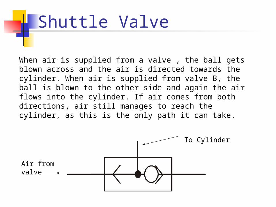
When air is supplied from a valve , the ball gets blown across and the air is directed towards the cylinder. When air is supplied from valve B, the ball is blown to the other side and again the air flows into the cylinder. If air comes from both directions, air still manages to reach the cylinder, as this is the only path it can take.
To Cylinder
Air from valve

Pupil Activity - OR Control
Valve A Valve B
Shuttle valve
1) Copy down the circuit into your workbook
2) Build and test the circuit
3) Describe the operation of the circuit
4) The operation of the cylinder can be described by the following truth table
VALVE A
OFF
ON
OFF
ON
VALVE B
OFF
OFF
ON
ON
CYLINDER
INSTROKE
OUTSTROKE
OUTSTROKE
OUTSTROKE

Pupil Activity
CLOSE (OUTSIDE)
CLOSE (INSIDE)
OPEN (OUTSIDE)
OPEN (INSIDE)
A pneumatic circuit has been devised for use in operating a sliding door. It must be possible for the door to be opened or closed from both the inside and outside. The speed of the door should be controlled when opening and closing.
Design, build and test a circuit to control the door movement.

Time Delays
Sometimes in a circuit we want a pause or delay before something else happens.
To create a delay we need to use three components – a unidirectional restrictor, a T-piece and a reservoir.
A reservoir is simply an empty container, just like an empty bottle. The bigger the reservoir, the longer it takes to fill up with air. To make the delay longer we use a unidirectional restrictor in front of the reservoir. This slows down the air so that the reservoir takes even longer to fill. The length of time it takes to fill creates the delay.

Time Delays
Air
Uni-Directional Flow Control Restrictor
Reservoir
T-Piece
We can change the length of a delay by changing the size of the reservoir or adjusting the restrictor.

Pupil Activity
Copy the circuit intoyour workbook
Build and test the circuit shown.
Adjust the restrictor to achieve a time delay of three seconds.

Circuit Operation
When the push button is pressed, the 5/2 valve changes state and the cylinder outstrokes.
As it outstrokes, it pushes the former together and the hot plastic sheet is pressed into shape.
As this happens it also actuates the roller. Air now flows through the restrictor and starts to fill up the reservoir.
Once the reservoir is full, the 5/2 valve changes state and the cylinder instrokes, ready for the process to begin again.
Air Bleed / Diaphragm Valve
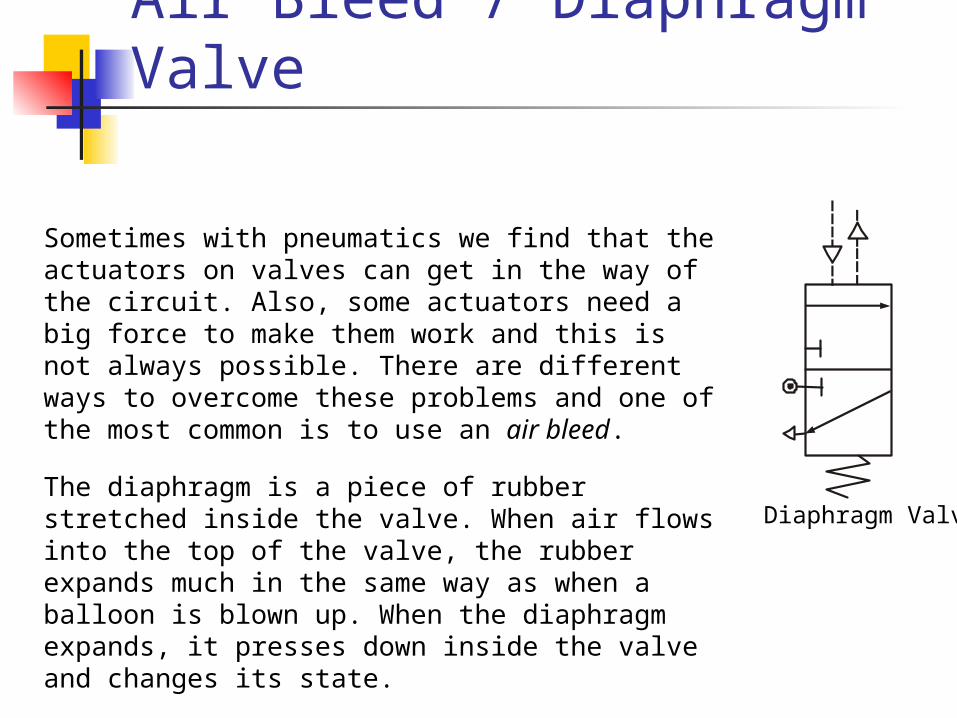
Sometimes with pneumatics we find that the actuators on valves can get in the way of the circuit. Also, some actuators need a big force to make them work and this is not always possible. There are different ways to overcome these problems and one of the most common is to use an air bleed.
Diaphragm ValveThe diaphragm is a piece of rubber stretched inside the valve. When air flows into the top of the valve, the rubber expands much in the same way as when a balloon is blown up. When the diaphragm expands, it presses down inside the valve and changes its state.

Pupil Activity - Box Sensor
Air bleed symbol
Copy the circuit into your workbook.
Build and test the circuit.
Explain why an air bleed might be used to sense boxes on a conveyer belt.
Someone has noticed that the cylinder outstrokes so fast that there is a risk that the boxes may be damaged. Alter the circuit to slow down the operation of the single-acting cylinder.

Automatic Circuits
Automatic circuitsAutomatic circuits are commonly found on production lines. They help to speed up production and make sure that the goods are all manufactured to the same standard. There are two types of automatic circuit: semi-automatic and fully automatic.
Semi-automaticA semi-automatic circuit is one that completes a process once it has been started, usually by a human operator. We have come across semi-automatic circuits already in the course.

Pupil Activity – Semi auto
Copy the circuit intoyour workbook
Build and test the circuit shown.
Adjust the restrictor to achieve a time delay of three seconds.

Forces in Cylinders
The force produced when a single-acting cylinder outstrokes is calculated using the formula:
Force = Pressure x Area
Note: This formula is in your data book USE IT Pressure = Force
Area
Area = Force Pressure
We can also rearrange these formula to find other quantities.

Forces in Cylinders - SAC
Air is supplied to a single-acting cylinder at a pressure of 4 N/mm2. The diameter of the piston is 25 mm. Calculate the force produced as the piston outstrokes.
Write down what you already know
Write down the formula
Calculate the area
Complete the calculationYour teacher will now go through the solution on the white board

Pupil Assignments
1. Write down the formula that we use to calculate the force in a single-acting cylinder as it outstrokes.
2. A pneumatic stamping machine is used to stamp the company logo onto metal casings. It is discovered that the stamp does not imprint the logo properly. Suggest ways of increasing the size of the force produced by the cylinder.
3. What controls the instroke of a single-acting cylinder?
Pupil Assignments
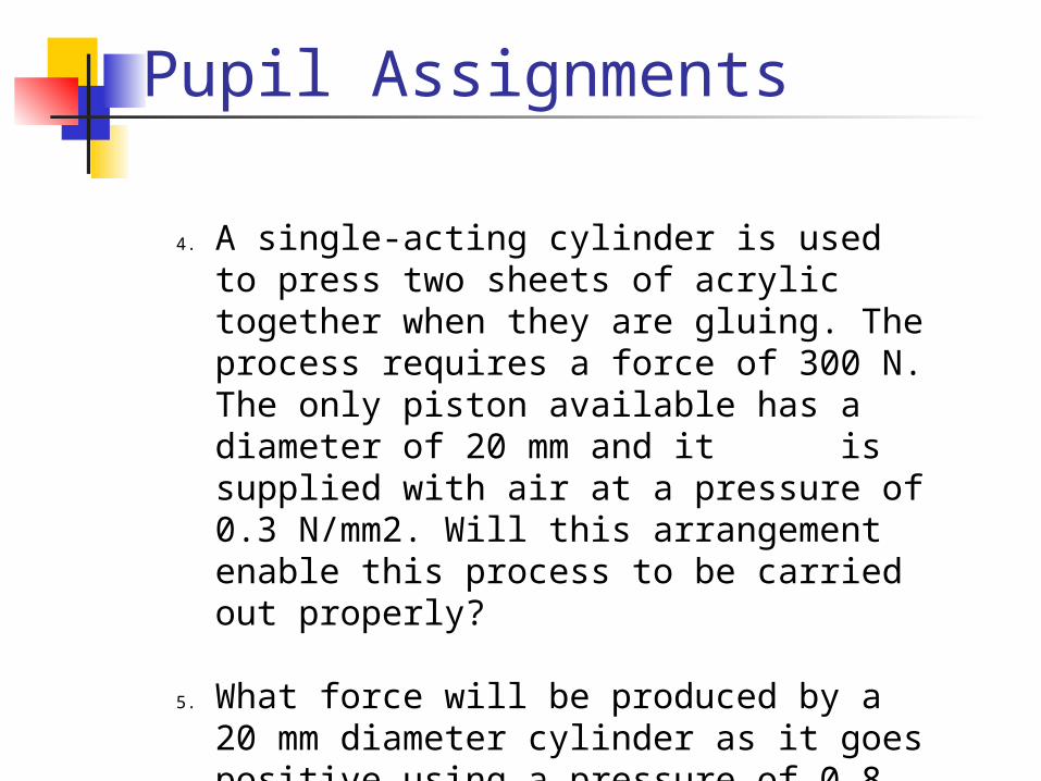
4. A single-acting cylinder is used to press two sheets of acrylic together when they are gluing. The process requires a force of 300 N. The only piston available has a diameter of 20 mm and it is supplied with air at a pressure of 0.3 N/mm2. Will this arrangement enable this process to be carried out properly?
5. What force will be produced by a 20 mm diameter cylinder as it goes positive using a pressure of 0.8 N/mm2?

Pupil Assignments
6. Write down the formula that we would use to calculate the pressure of a system if we already knew the force required and the size of the cylinder available.
7. A stamping machine exerts a force of 454 N with a piston diameter of 34 mm. Calculate the air pressure required for this operation.
8. A machine that places tops on bottles uses a single-acting cylinder. The process requires a force of 650 N. What air pressure needs to be supplied to the cylinder with a diameter of 56 mm?

Pupil Assignments9. A force of 540 N is needed to push a packing
case off a conveyor belt. The single-acting cylinder used has a diameter of 60 mm. What air pressure should be supplied to the system?
10. A pneumatic system is used to test the quality of drawer guides in kitchen cabinets. A force of 16 N is needed to open the drawer. The single-acting cylinder available has a piston diameter of 10 mm. What air pressure should be supplied?
11. Write down the formula we would use to find the area of a piston if we already knew the size of the force it needed to produce and the air pressure being supplied.

Solutions to Sac problems
1) F=PA2) Increase pressure or increase piston area3) Spring4) 94.2N5) 251.2N6) P=F/A7) 0.5N/mm2
8) 0.6N/mm2
9) 0.19N/mm2
10) 0.2N/mm2
11) A=F/P

Forces in Cylinders - DAC
We already know that a double-acting cylinder can be much more useful to us in pneumatics because both the outstroke and instroke are controlled by compressed air. This allows us to make use of both the outstroke and the instroke force. What we learn, however, is that the outstroke force is greater than the instroke force. Why is this the case?
During the outstroke, the compressed air pushes against the surface area of the piston in the same way as in the single-acting cylinder.

Forces in Cylinders - DAC
However, during the instroke the surface area is reduced because of the piston rod. This means that the compressed air does not have as big an area to push against and so it does not produce as big a force.
Effective area = piston area – piston rod area

Worked Example
A double-acting cylinder has a piston with a diameter of 25 mm. The piston rod is 5 mm in diameter. Pressure is supplied to the system at 4 N/mm2. Calculate the force produced by the cylinder as it outstrokes and instrokes.
Your teacher will now work through the problem on the white board

Pupil Assignments1. Explain why the forces produced by a double-
acting cylinder on the outstroke and instroke are different.
2. A double-acting cylinder found in a Technological Studies room has a piston diameter of 20 mm and is supplied with air at a pressure of 0.3 N/mm2. What force is produced as the piston outstrokes? The piston rod has a diameter of 6 mm. What force is produced on the instroke?
3) A double-acting cylinder is used to raise and lower a barrier in a car park. The air pressure is 0.4 N/mm2 and the piston has a diameter of 40 mm. The piston rod is 12 mm in diameter. What forces are produced when the piston outstrokes and instrokes?
Pupil Assignments
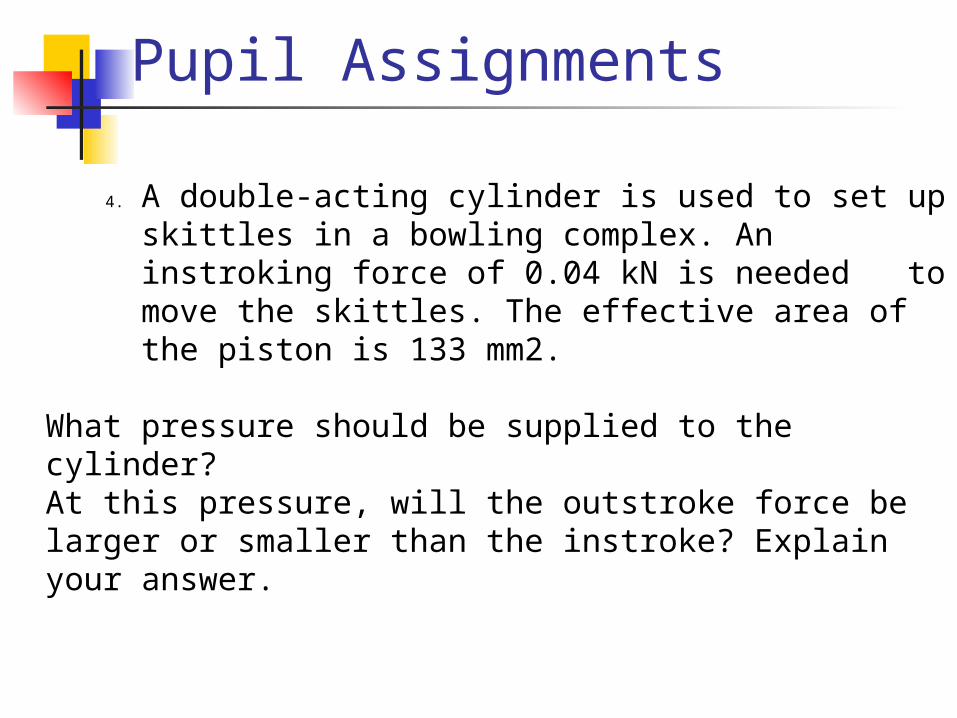
4. A double-acting cylinder is used to set up skittles in a bowling complex. An instroking force of 0.04 kN is needed to move the skittles. The effective area of the piston is 133 mm2.
What pressure should be supplied to the cylinder?At this pressure, will the outstroke force be larger or smaller than the instroke? Explain your answer.

Pupil Assignments5. Components on a conveyor system travel
along and drop onto a table attached to the end of a double-acting cylinder.
As the cylinder instrokes, the components are raised up and then pushed by another cylinder on to the next conveyor. The piston diameter is 20 mm and air is supplied at a pressure of 0.45 N/mm2. The effective area is 200 mm2.
Calculate the instroke force and say whether the system could lift a component weighing 100 N.
Someone suggests turning the double-acting cylinder round so that the components are lifted by the outstroke. Is the system now able to raise the components? Explain your answer.

Work Done
We can also calculate the work done by a pneumatic cylinder.
Work Done (W) = Force (F) x Distance (d) (or x)
The units of work are JOULES.
If we have a single acting cylinder which produces a positive going force of 200N and has a piston rod STROKE of 100mm (length piston rod moves out), the work done is given by,
W = Fs
W = 200 x 100 = 20000 Nmm (1 Joule = 1Nm)
W = 20J

Work Done
Pupil Problem
A Double acting cylinder is used to lift parcels from one level to another. The cylinder has a piston of 50mm diameter a piston rod of 10mm diameter and a working pressure of 4n/mm2. The cylinder stroke is 300mm. Calculate the following,
a) The Work done outstroking
b) The negative (in stroke) force.Level 1
Level 2
Cylinder
Parcel
Remember 1 Joule is = to 1Nm

Electronic Control
There are many advantages in controlling pneumatic circuits with electronics. First, electronic signals are faster than pneumatic signals, so circuits respond much more quickly. We can also carry electrical signals over longer distances than pneumatic signals. Finally, electronic components are much smaller than pneumatic actuators, which can be bulky and interfere with the operation of a circuit.
To control a pneumatic circuit with electronics we need to use a solenoid-operated valve
Pupil Demonstration
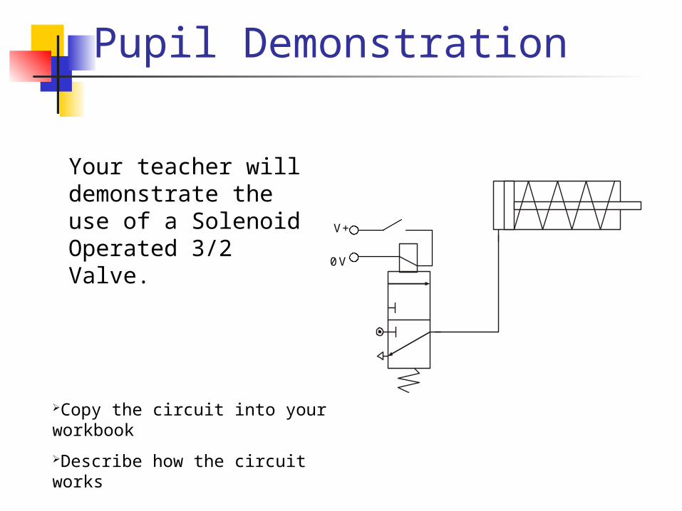
V+
0 V
Your teacher will demonstrate the use of a Solenoid Operated 3/2 Valve.
Copy the circuit into your workbook
Describe how the circuit works