Pneumatics. Pneumatics is a subsection of an area known as fluid power. Makes use of air which is a...
47
Pneumatics Pneumatics
-
date post
22-Dec-2015 -
Category
Documents
-
view
231 -
download
3
Transcript of Pneumatics. Pneumatics is a subsection of an area known as fluid power. Makes use of air which is a...

Pneumatics
Pneumatics

Pneumatics
Pneumatics is a subsection of an area known as fluid power.
Makes use of air which is a colourless, odourless and tasteless gas consisting of approximately 78% Nitrogen and 20% Oxygen. The remaining 2% consists of about 1% Argon and a mixture of other trace elements such as helium, hydrogen and neon
Widely used in Industry where it uses pressurised air, more commonly called compressed air to do work and effect mechanical motion,
Used worldwide in the construction and mining industries, manufacturing and transport systems, packaging, diving and dentistry.
Why is it so popular?

Pneumatics
Preferred system of use because of its availability and safety attributes.
Advantages
• Unlimited free supply
• Storage
• Easily Transportable
• Clean
• Explosion proof
• Controllable (Speed, Force)
• Overload Safe
Disadvantages
• Cost (Inefficient)
• Preparation
• Noise Pollution
• Limited Range of Force(only economical up to 25kN)
Pneumatics
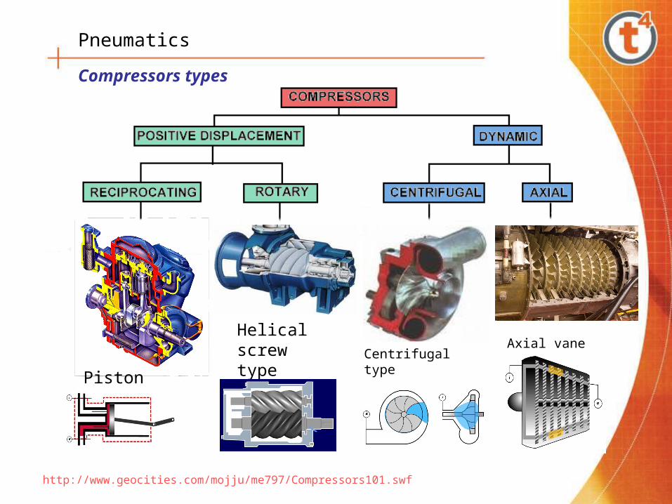
Compressors types
Piston type
Helical screw type Axial vane type
Centrifugal type
http://www.geocities.com/mojju/me797/Compressors101.swf

Pneumatics
Piston at the starting position, Top of cylinder, both valves closed.
Single Piston compressor cycle
Piston moving down outlet valve closed, Inlet valve open taking in Air.
Piston moving up, both valves closed, air is being compressed.
Nearing the end of the compression, the outlet valve opens sending the compressed air to the storage tank.
Inlet InletInletInletOutlet Outlet Outlet Outlet

Pneumatics
Typical Industrial system layout
Separators
Compressor
Reservoir
Dryer
Filters
Pipe distribution
Slope 1.5%

Pneumatics
Pneumatic symbol
Valves and Actuators
Physical appearancePneumatic symbol
Pneumatic symbol
Physical appearance
Physical appearance
Pneumatic symbol
Physical appearance

Pneumatics
Reading pneumatic symbols
Squares represent the valve switching positions.
The number of squares represents the number of switching positions.
Lines indicate flow path and arrows the direction of flow.
Lines drawn at right angles in boxes indicate shut off positions.
Inlet and outlet ports are shown by lines on the outside of the box and in their initial positions.
Air pressure supply from the compressor.Exhaust port

Pneumatics
2
1 3
2
1 3
2
1 3
2
1 3pushbutton
Pushbutton, detent
Proximity switch
Pneumatic pilot
Solenoid
Reading pneumatic symbols
4 2
51
3
3/2 Way directional control valve normally closed
3/2 Way directional control valve normally open
5/2 Way directional control valve
Number of Ports.
Number of Positions
Number of Ports.
Number of Positions
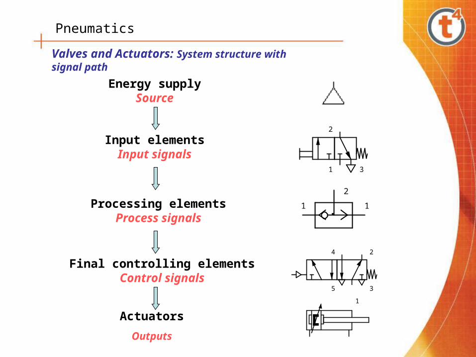
Pneumatics
Energy supplySource
Input elementsInput signals
2
1 3
Processing elementsProcess signals
1 1
2
Final controlling elementsControl signals
4 2
5
1
3
Actuators
Outputs
Valves and Actuators: System structure with signal path
Pneumatics
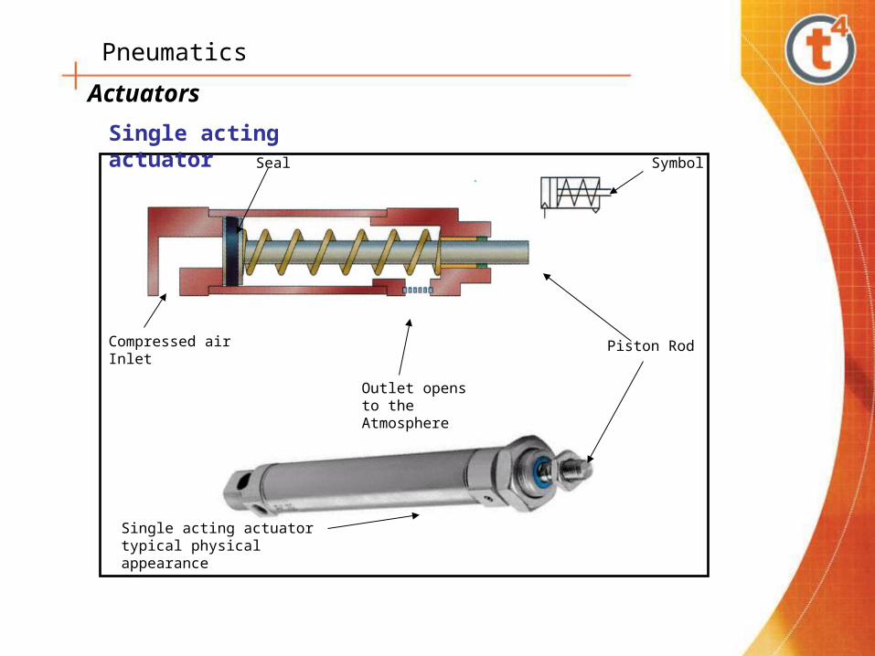
Actuators
Single acting actuator typical physical appearance
Piston RodCompressed air Inlet
Outlet opens to the Atmosphere
SymbolSeal
Single acting actuator
Pneumatics
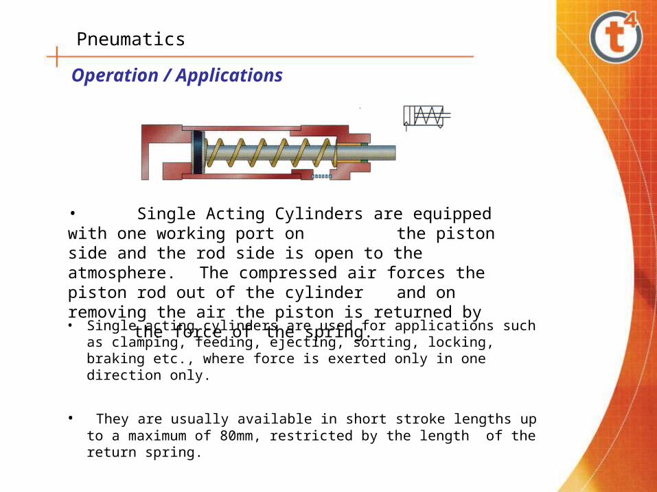
• Single acting cylinders are used for applications such as clamping, feeding, ejecting, sorting, locking, braking etc., where force is exerted only in one direction only.
• They are usually available in short stroke lengths up to a maximum of 80mm, restricted by the length of the return spring.
Operation / Applications
• Single Acting Cylinders are equipped with one working port on the piston side and the rod side is open to the atmosphere.
The compressed air forces the piston rod out of the cylinder and on removing the air the piston is returned by the force of the spring.

Pneumatics
Double acting actuator
Symbol
Compressed air may be applied to both ports
Seals
Piston rod
Flow control valves
Mounting bracket

Pneumatics
• Double Acting Cylinders are equipped with two working ports- one on the piston side and the other on the rod side.
• Forward motion of the cylinder is achieved by connecting compressed air to the piston side and the rod side is connected to the exhaust.
• During return stroke the air supply is connected to the rod side while the piston side connected to the exhaust. Force is exerted by the piston during both the forward and return motion of cylinder
• Double acting cylinders are available in diameters from a few mm to around 300 mm and stroke lengths of a few mm up to 2 meters.
Operation / Applications
Pneumatics
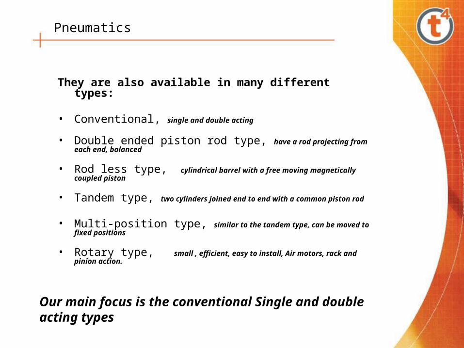
They are also available in many different types:
• Conventional, single and double acting
• Double ended piston rod type, have a rod projecting from each end, balanced
• Rod less type, cylindrical barrel with a free moving magnetically coupled piston
• Tandem type, two cylinders joined end to end with a common piston rod
• Multi-position type, similar to the tandem type, can be moved to fixed positions
• Rotary type, small , efficient, easy to install, Air motors, rack and pinion action.
Our main focus is the conventional Single and double acting types
Pneumatics
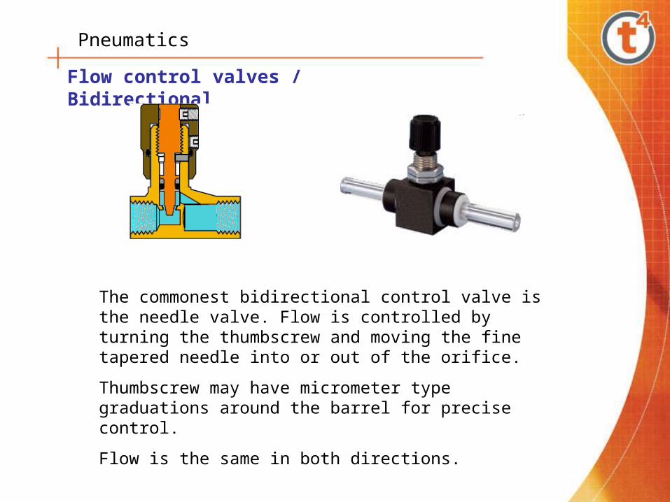
Flow control valves / Bidirectional
The commonest bidirectional control valve is the needle valve. Flow is controlled by turning the thumbscrew and moving the fine tapered needle into or out of the orifice.
Thumbscrew may have micrometer type graduations around the barrel for precise control.
Flow is the same in both directions.
Pneumatics
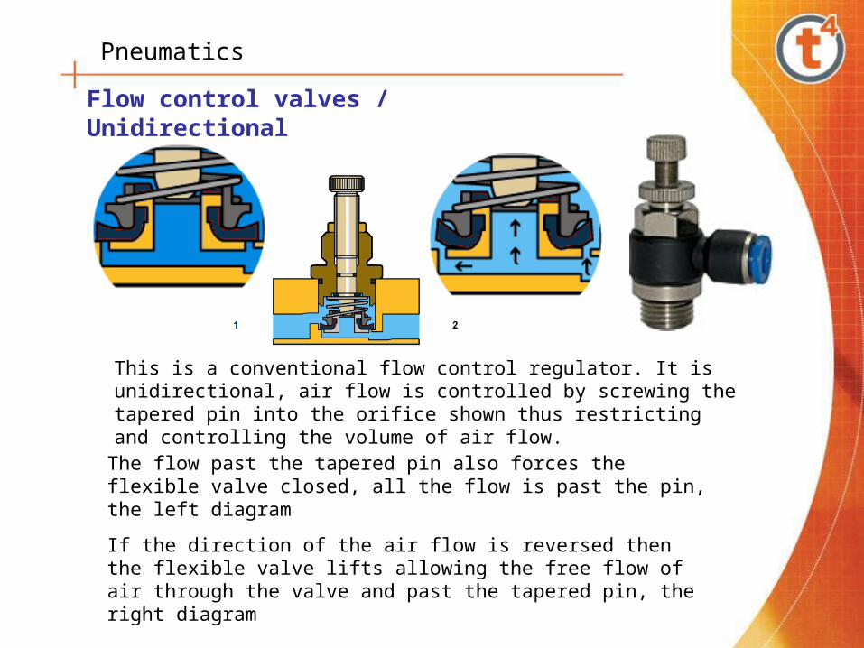
Flow control valves / Unidirectional
This is a conventional flow control regulator. It is unidirectional, air flow is controlled by screwing the tapered pin into the orifice shown thus restricting and controlling the volume of air flow.
The flow past the tapered pin also forces the flexible valve closed, all the flow is past the pin, the left diagram
If the direction of the air flow is reversed then the flexible valve lifts allowing the free flow of air through the valve and past the tapered pin, the right diagram

Pneumatics
Spool valves
Spool
Return spring
Open to the atmosphere
Initial state Activated state
Seals
Exhaust
Spool
Air inlet
To actuatorFrom actuator2
1 3
2
31

Pneumatics
Poppet valves
Initial stateActivated state
Exhaust
Air inlet
To actuatorFrom actuator
Seals
Seals
Return spring
2
31
2
1 3

Pneumatics
Flow control valves / Quick exhaust
Physical appearanceCutaway section showing poppet valve positions
Used to increase piston speed.
When air flow is from port 1 to port 2 the poppet valve is kept closed under the supplied pressure.
When operated in the reverse direction the lower pressure on port 1 allows the poppet valve to open rapidly and channel the air out through the much larger opening giving the quick exhaust.
Pneumatics
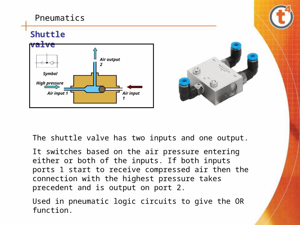
Shuttle valve
Air input 1 Air input 1
Air output 2
Symbol
High pressure
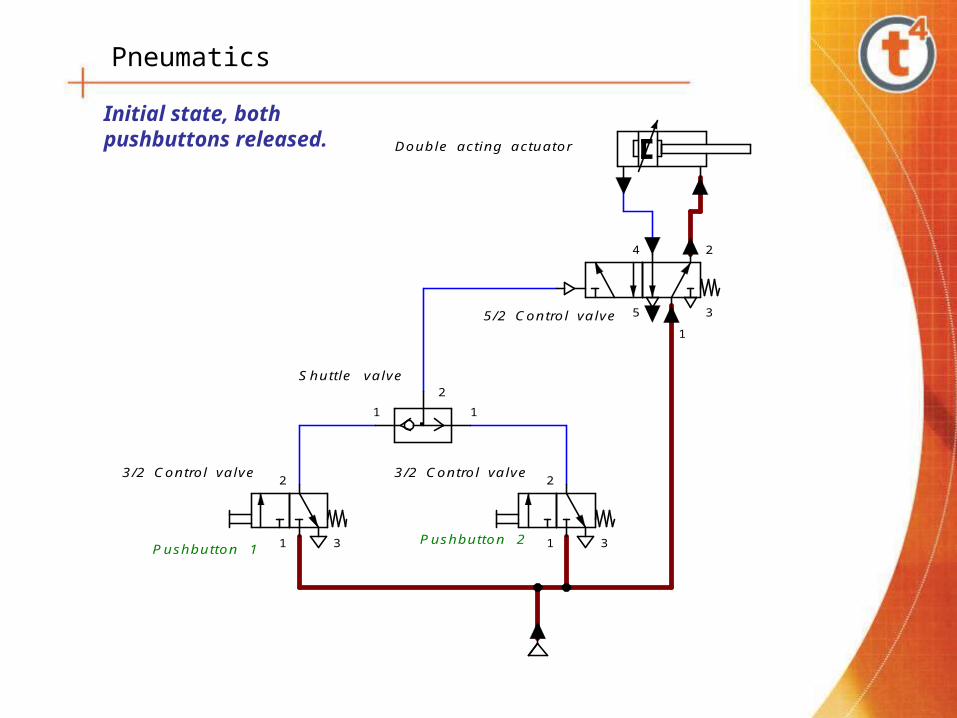
The shuttle valve has two inputs and one output.
It switches based on the air pressure entering either or both of the inputs. If both inputs ports 1 start to receive compressed air then the connection with the highest pressure takes precedent and is output on port 2.
Used in pneumatic logic circuits to give the OR function.

Pneumatics
Two pressure valve
Physical appearance the same as the shuttle valve, internally different.
Compressed air enters either or both ports 1 and outputs on port 2.
If both ports 1 receive compressed air then the connection with the lower pressure takes precedent and outputs on port 2.
Used to provide the AND function in pneumatic logic circuits.
Pneumatics
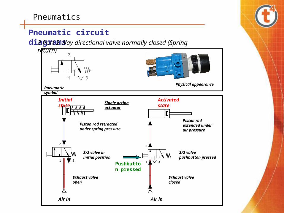
Pneumatic circuit diagrams
Physical appearancePneumatic symbol
3 Port 2 Way directional valve normally closed (Spring return)
Air in
3/2 valve pushbutton pressed
Piston rod extended under air pressure
Activated state
Exhaust valve closed
2
1 3
Air in
3/2 valve in initial position
Piston rod retracted under spring pressure
Exhaust valve open
Single acting actuatorInitial state
2
1 3Pushbutton pressed
Pneumatics
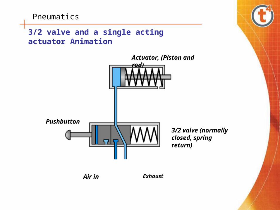
3/2 valve and a single acting actuator Animation
Air in Exhaust
Pushbutton
3/2 valve (normally closed, spring return)
Actuator, (Piston and rod)

Pneumatics
Pneumatic symbol
Physical appearance
4 2
5
1
3
4 2
5
1
3
5/2 valve in initial position
5/2 valve in activate position
Air inlet Air inlet
Exhaust Exhaust
Piston retracted under air pressure
Piston extended under air pressure
Double acting actuator
Pushbutton pressed
5 Port 2 Way directional valve, pushbutton spring return.
Pneumatics
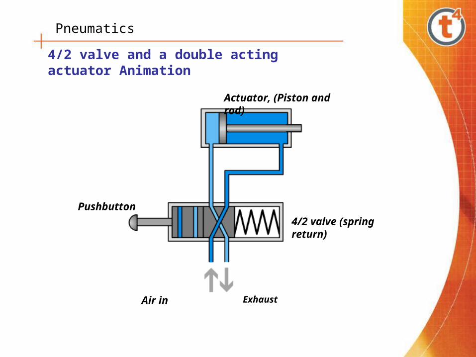
4/2 valve and a double acting actuator Animation
Actuator, (Piston and rod)
Pushbutton
Air in Exhaust
4/2 valve (spring return)
Pneumatics
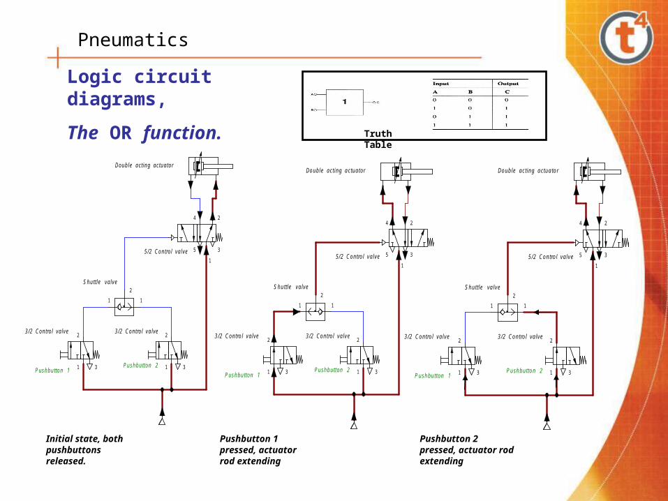
Logic circuit diagrams,
The OR function.Truth Table
1 1
2
2
1 3
4 2
5
1
3
Pushbutton 1Pushbutton 2
Shuttle valve
5/2 Control valve
3/2 Control valve 3/2 Control valve
Double acting actuator
2
1 3
Initial state, both pushbuttons released.
Pushbutton 1 pressed, actuator rod extending
1 1
2
2
1 3
4 2
5
1
3
Pushbutton 1Pushbutton 2
Shuttle valve
5/2 Control valve
3/2 Control valve 3/2 Control valve
Double acting actuator
2
1 3
1 1
2
2
1 3
4 2
5
1
3
Pushbutton 1Pushbutton 2
Shuttle valve
5/2 Control valve
3/2 Control valve 3/2 Control valve
Double acting actuator
2
1 3
Pushbutton 2 pressed, actuator rod extending
Pneumatics
1 1
2
2
1 3
4 2
5
1
3
Pushbutton 1Pushbutton 2
Shuttle valve
5/2 Control valve
3/2 Control valve 3/2 Control valve
Double acting actuator
2
1 3
Initial state, both pushbuttons released.

Pneumatics
1 1
2
2
1 3
4 2
5
1
3
Pushbutton 1Pushbutton 2
Shuttle valve
5/2 Control valve
3/2 Control valve 3/2 Control valve
Double acting actuator
2
1 3
Pushbutton 1 pressed, actuator rod extending
Pneumatics
1 1
2
2
1 3
4 2
5
1
3
Pushbutton 1Pushbutton 2
Shuttle valve
5/2 Control valve
3/2 Control valve 3/2 Control valve
Double acting actuator
2
1 3
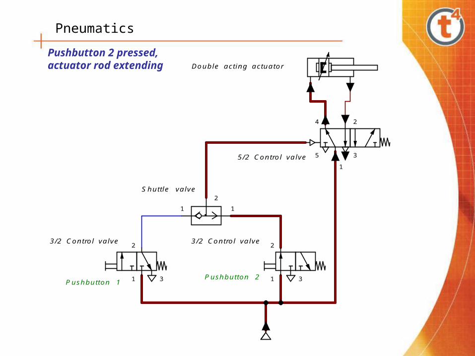
Pushbutton 2 pressed, actuator rod extending

Pneumatics
Logic circuit diagrams,
The AND function.Truth Table
1 12
2
1 3
2
1 3
4 2
5
1
3
Double acting actuator
Pushbutton 1 Pushbutton 2
Two pressure valve
Compressed air
5/2 control valve
3/2 control valve3/2 Control valve
Pilot port
Circuit in its initial state, neither pushbutton activated
1 12
2
1 3
2
1 3
4 2
5
1
3
Double acting actuator
Pushbutton 1 Pushbutton 2
Two pressure valve
Compressed air
5/2 control valve
3/2 control valve3/2 Control valve
Pilot port
Pushbutton 1 activated, no change in actuator
1 1
2
2
1 3
2
1 3
4 2
5
1
3
Double acting actuator
Pushbutton 1 Pushbutton 2
Two pressure valve
Compressed air
5/2 control valve
3/2 control valve3/2 Control valve
Pilot port
Pushbutton 2 activated, no change in actuator
1 1
2
2
1 3
2
1 3
4 2
5
1
3
Double acting actuator
Pushbutton 1 Pushbutton 2
Two pressure valve
Compressed air
5/2 control valve
3/2 control valve3/2 Control valve
Pilot port
Both pushbuttons activated, compressed air delivered to the actuator under the action of the two pressure valve. Piston rod begins to extend.

Pneumatics
1 1
2
2
1 3
2
1 3
4 2
5
1
3
Double acting actuator
Pushbutton 1 Pushbutton 2
Two pressure valve
Compressed air
5/2 control valve
3/2 control valve3/2 Control valve
Pilot port
Circuit in its initial state, neither pushbutton activated
Logic circuit diagrams,
The AND function.

Pneumatics
1 1
2
2
1 3
2
1 3
4 2
5
1
3
Double acting actuator
Pushbutton 1 Pushbutton 2
Two pressure valve
Compressed air
5/2 control valve
3/2 control valve3/2 Control valve
Pilot port
Pushbutton 1 activated, no change in actuator
Logic circuit diagrams,
The AND function.

Pneumatics
1 1
2
2
1 3
2
1 3
4 2
5
1
3
Double acting actuator
Pushbutton 1 Pushbutton 2
Two pressure valve
Compressed air
5/2 control valve
3/2 control valve3/2 Control valve
Pilot port
Pushbutton 2 activated, no change in actuator
Logic circuit diagrams,
The AND function.

Pneumatics
1 12
2
1 3
2
1 3
4 2
51
3
Double acting actuator
Both pushbuttons activated, compressed air delivered to the actuator under the action of the two pressure valve. Piston rod begins to extend. If either pushbuttons are released then the circuit returns to its initial state.
Pushbutton 1 Pushbutton 2
Two pressure valve
Compressed air
5/2 control valve
3/2 control valve 3/2 Control valve
Pilot port
Logic circuit diagrams,
The AND function.

Pneumatics
Simple solenoid controlled circuit
2
1 3
1S1
0V
+24V
1S1
2
1 3
1S1
0V
+24V
1S1
Initial state
Solenoid switch operated
Switch, mechanical or reed.
Solenoid
Electrical control side
Operational side
There are two parts to this circuit, the electrical circuit and the mechanical operational circuit
It consists of a 24 volt supply, a switch and a solenoid on the electrical side.
The operational side consists of a single acting actuator, a solenoid controlled 3/2 valve and an air supply.
In it’s initial state the electrical circuit is broken as the switch is open. The actuator is at rest (exhaust position) through the operation of the 3/2 valve.
Closing the switch brings in the solenoid, operating the 3/2 valve and extending the piston rod.
When the switch is opened again the circuit returns to it’s initial position.

Pneumatics
Solenoid controlled delay circuit
1Y1
+24V
0V
SW1
K1
K1
4 2
1 3
1Y1 1Y2
1Y2
K2
K2 5
Text
Text
1Y1
+24V
0V
SW1
K1
K1
4 2
1 3
1Y1 1Y2
1Y2
K2
K2 2.4
Text
Text
1Y1
+24V
0V
SW1
K1
K1
4 2
1 3
1Y1 1Y2
1Y2
K2
K2 5
Text
Text
1Y1
+24V
0V
SW1
K1
K1
4 2
1 3
1Y1 1Y2
1Y2
K2
K2 5
Stage 1
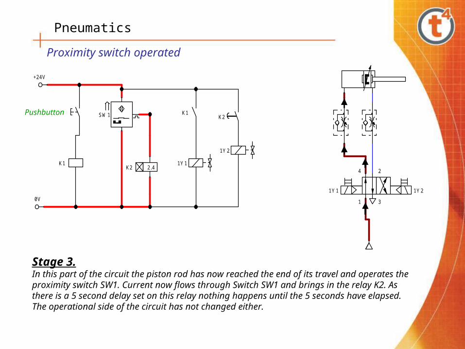
Stage 3
Stage 2
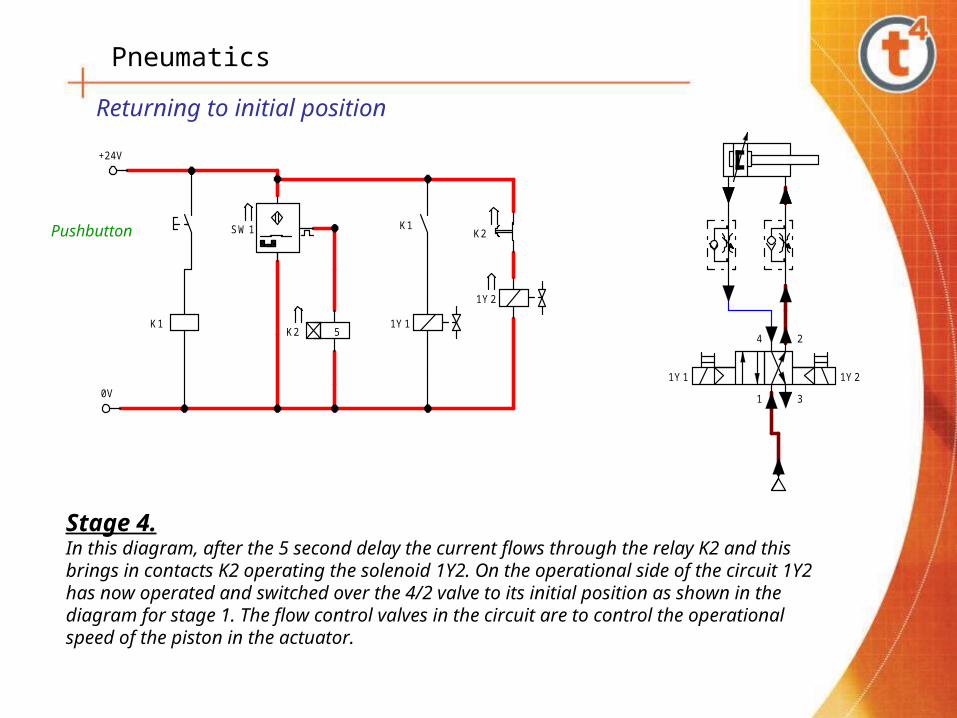
Stage 4

Pneumatics
Stage 1This is the circuit layout in its initial position. On the electrical side you have a pushbutton switch, a relay K1, a proximity switch SW1, a second relay K2 with a 5 second delay set and two solenoids 1Y1 and 1Y2. In this case the supply voltage is 24 volts DC. The operational side has a double acting actuator, two flow controls and a 4/2 directional control valve with two solenoids. In its initial state the electrical circuit is inactive and there is a supply of compressed air flowing from port 1 to port 2 keeping the actuator piston retracted.
Circuit Initial position
Pushbutton
Text
Text
1Y1
+24V
0V
SW1
K1
K1
4 2
1 31Y1 1Y2
1Y2
K2
K2 5
Pneumatics
1Y1
+24V
0V
SW1
K1
K1
4 2
1 3
1Y1 1Y2
1Y2
K2
K2 5
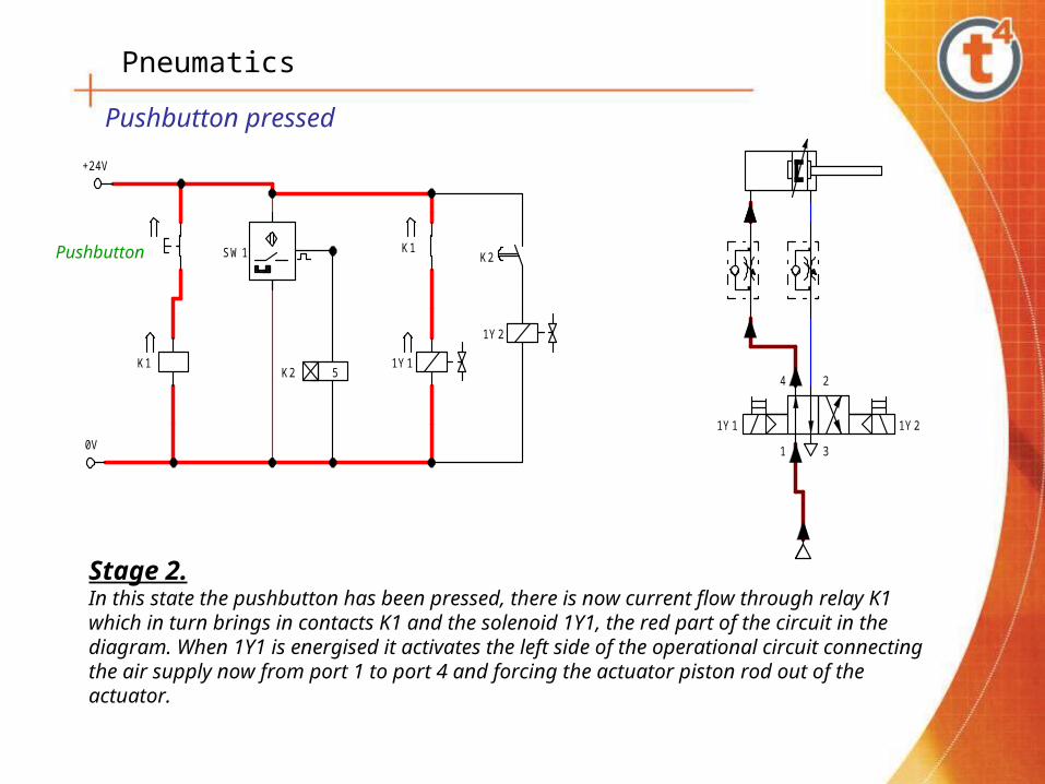
Stage 2.In this state the pushbutton has been pressed, there is now current flow through relay K1 which in turn brings in contacts K1 and the solenoid 1Y1, the red part of the circuit in the diagram. When 1Y1 is energised it activates the left side of the operational circuit connecting the air supply now from port 1 to port 4 and forcing the actuator piston rod out of the actuator.
Pushbutton pressed
Pushbutton
Pneumatics
Pushbutton
Stage 3.In this part of the circuit the piston rod has now reached the end of its travel and operates the proximity switch SW1. Current now flows through Switch SW1 and brings in the relay K2. As there is a 5 second delay set on this relay nothing happens until the 5 seconds have elapsed. The operational side of the circuit has not changed either.
Text
Text
1Y1
+24V
0V
SW1
K1
K1
4 2
1 3
1Y1 1Y2
1Y2
K2
K2 2.4
Proximity switch operated
Pneumatics
Text
Text
1Y1
+24V
0V
SW1
K1
K1
4 2
1 3
1Y1 1Y2
1Y2
K2
K2 5
Pushbutton
Stage 4.In this diagram, after the 5 second delay the current flows through the relay K2 and this brings in contacts K2 operating the solenoid 1Y2. On the operational side of the circuit 1Y2 has now operated and switched over the 4/2 valve to its initial position as shown in the diagram for stage 1. The flow control valves in the circuit are to control the operational speed of the piston in the actuator.
Returning to initial position

Pneumatics
PLC programming.
Standalone PLC programmer
Programmer connected to a Laptop, controlled using a programming Language known as Ladder Logic.
Software circuit layout to control a Double acting actuator with a Solenoid valve using a PLC programmer.
PLC
Solenoid valve Solenoid valve
Reed sensor

Pneumatics
Simple SMC control programme.
The programme starts and goes to the decision box, checks to see if Input 7 is High. If it is low it goes around the right hand loop and checks again until it gets a
High. When Input 7 is High, it makes Output 1 High. It then waits 1 second and makes Output 1 low. It follows to loop around to the top of the decision box and checks again for the next cycle. This simple programme switches on and off the Solenoid controlling the flow of compressed air to the Actuator.
Pneumatics
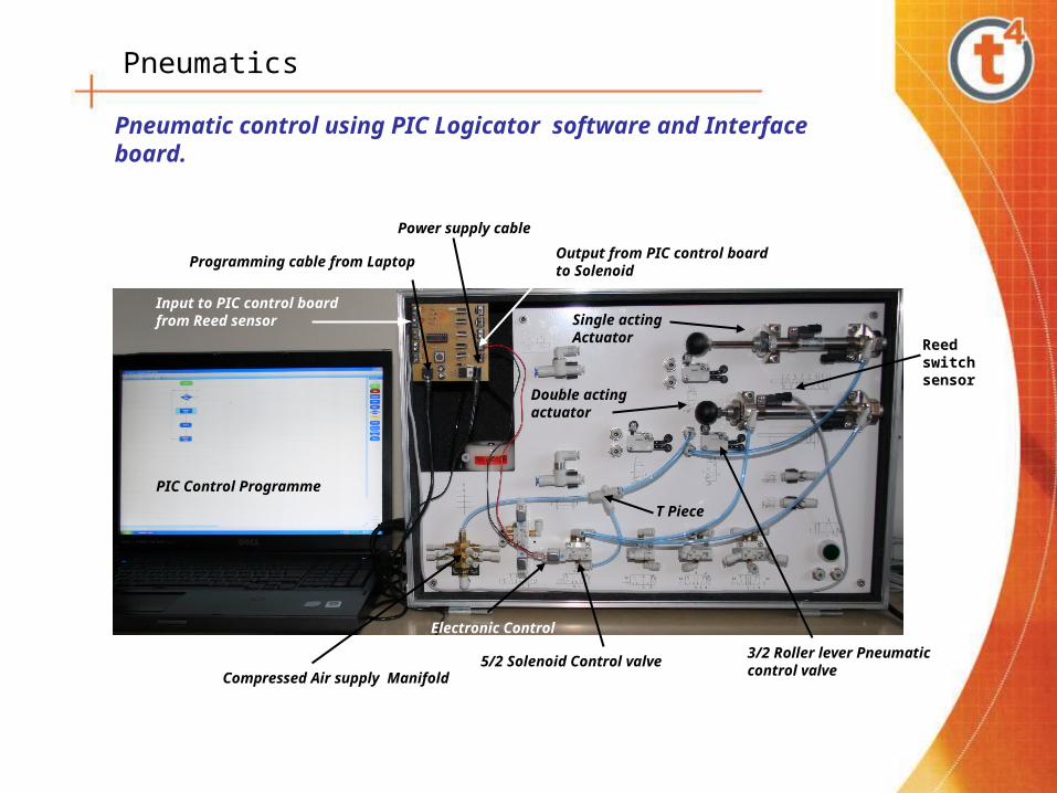
Pneumatic control using PIC Logicator software and Interface board.
Programming cable from Laptop
Power supply cable
Compressed Air supply Manifold
5/2 Solenoid Control valve
Single acting Actuator
Double acting actuator
3/2 Roller lever Pneumatic control valve
PIC Control Programme
T Piece
Output from PIC control board to Solenoid
Input to PIC control board from Reed sensor
Reed switch sensor
Electronic Control

Pneumatics
Safety requirementsGeneral workshop requirements
All pipes, hoses, and fittings must have a rating of the maximum pressure of the compressor. Compressed air pipelines should be identified (psi) as to maximum working pressure.
Air supply shutoff valves should be located (as near as possible) at the point-of-operation. Hoses should not be left lying on the floors where they are likely to cause people to trip and fall..
Compressed air must not be used under any circumstances to clean dirt and dust from clothing or off a person’s skin. Workshop air used for cleaning should be regulated to 15 psi unless equipped with diffuser nozzles to provide a lower pressure.
Air receivers/reservoirs:The maximum allowable working pressures of air receivers should never be exceeded except when being tested. No tank or receiver should be altered or modified by unauthorised persons.Reservoir/receivers should be drained frequently to prevent accumulation of liquid inside the unit.
A safety (spring loaded) release valve should be installed to prevent the receiver from exceeding the maximum allowable working pressure.

Pneumatics
Safety requirements Pressure regulation Devices:
Only qualified personnel should be allowed to repair or adjust pressure regulating equipment.
Air tank safety valves should be set no less than 15 psi or 10 percent (whichever is greater) above the operating pressure of the compressor but never higher than the maximum allowable working pressure of the air receiver.
Air lines between the compressor and receiver should not usually be equipped with stop valves.
Air Compressor Operation:
The air intake should be from a clean, outside, fresh air source. Filters should be used to clean the air.
Air compressors should never be operated at speeds faster than the manufacturer’s recommendation.
Moving parts, such as compressor flywheels, pulleys, and belts that could be dangerous should be guarded.
More detailed safety requirements are to be found in the notes.

Pneumatics
Pneumatic notes:
The supplied pneumatic notes contain a more detailed description of the material covered in these slides with the addition of sample worked problems associated with actuators and actuator selection.
Suggested sample pneumatic applications and questions are also included at the back of the notes.
Finally included is a glossary of the most frequently encountered pneumatic terminology.


![Radon and Health - Canadian Nuclear Safety Commission · 2012-06-22 · Radon gas is odourless, tasteless and colourless, and therefore cannot be detected by the human senses [1].](https://static.fdocuments.in/doc/165x107/5f235982aea53a366a24056a/radon-and-health-canadian-nuclear-safety-commission-2012-06-22-radon-gas-is.jpg)