Pneumatic Transducer Tester - Flukeassets.fluke.com/manuals/dpm1b___umeng0100.pdf · aid in the...
24
PN 2572314 March 2006, Rev. 1, 4/15 © 2006-2015 Fluke Corporation. All rights reserved. Specifications are subject to change without notice. All product names are trademarks of their respective companies. DPM1B Pneumatic Transducer Tester Operators Manual
Transcript of Pneumatic Transducer Tester - Flukeassets.fluke.com/manuals/dpm1b___umeng0100.pdf · aid in the...
PN 2572314 March 2006, Rev. 1, 4/15 © 2006-2015 Fluke Corporation. All rights reserved. Specifications are subject to change without notice. All product names are trademarks of their respective companies.
DPM1B Pneumatic Transducer Tester
Operators Manual
Warranty and Product Support
Fluke Biomedical warrants this instrument against defects in materials and workmanship for one full year from the date of original purchase. During the warranty period, we will repair or, at our option, replace at no charge a product that proves to be defective, provided you return the product, shipping prepaid, to Fluke Biomedical. This warranty does not apply if the product has been damaged by accident or misuse or as the result of service or modification by other than Fluke Biomedical. IN NO EVENT SHALL FLUKE BIOMEDICAL BE LIABLE FOR CONSEQUENTIAL DAMAGES.
Only serialized products and their accessory items (those products and items bearing a distinct serial number tag) are covered under this one–year warranty. PHYSICAL DAMAGE CAUSED BY MISUSE OR PHYSICAL ABUSE IS NOT COVERED UNDER THE WARRANTY. Items such as cables and nonserialized modules are not covered under this warranty.
Recalibration of instruments is not covered under the warranty.
This warranty gives you specific legal rights, and you may also have other rights which vary from state to state, province to province, or country to country. This warranty is limited to repairing the instrument to Fluke Biomedical’s specifications.
Warranty Disclaimer
Should you elect to have your instrument serviced and/or calibrated by someone other than Fluke Biomedical, please be advised that the original warranty covering your product becomes void when the tamper-resistant Quality Seal is removed or broken without proper factory authorization. We strongly recommend, therefore, that you send your instrument to Fluke Biomedical for factory service and calibration, especially during the original warranty period.
Notices
All Rights Reserved Copyright 2006-2015, Fluke Biomedical. No part of this publication may be reproduced, transmitted, transcribed, stored in a retrieval system, or translated into any language without the written permission of Fluke Biomedical.
Copyright Release Fluke Biomedical agrees to a limited copyright release that allows you to reproduce manuals and other printed materials for use in service training programs and other technical publications. If you would like other reproductions or distributions, submit a written request to Fluke Biomedical.
Unpacking and Inspection Follow standard receiving practices upon receipt of the instrument. Check the shipping carton for damage. If damage is found, stop unpacking the instrument. Notify the carrier and ask for an agent to be present while the instrument is unpacked. There are no special unpacking instructions, but be careful not to damage the instrument when unpacking it. Inspect the instrument for physical damage such as bent or broken parts, dents, or scratches.
Technical Support For application support or answers to technical questions, either email [email protected] or call 1-800- 850-4608 or 1-440-248-9300. In Europe, email [email protected] or call +31-40-2965314.
Claims Our routine method of shipment is via common carrier, FOB origin. Upon delivery, if physical damage is found, retain all packing materials in their original condition and contact the carrier immediately to file a claim. If the instrument is delivered in good physical condition but does not operate within specifications, or if there are any other problems not caused by shipping damage, please contact Fluke Biomedical or your local sales representative.
Returns and Repairs Return Procedure
All items being returned (including all warranty-claim shipments) must be sent freight-prepaid to our factory location. When you return an instrument to Fluke Biomedical, we recommend using United Parcel Service, Federal Express, or Air Parcel Post. We also recommend that you insure your shipment for its actual replacement cost. Fluke Biomedical will not be responsible for lost shipments or instruments that are received in damaged condition due to improper packaging or handling.
Use the original carton and packaging material for shipment. If they are not available, we recommend the following guide for repackaging:
Use a double–walled carton of sufficient strength for the weight being shipped.
Use heavy paper or cardboard to protect all instrument surfaces. Use nonabrasive material around all projecting parts.
Use at least four inches of tightly packed, industry-approved, shock-absorbent material around the instrument.
Returns for partial refund/credit:
Every product returned for refund/credit must be accompanied by a Return Material Authorization (RMA) number, obtained from our Order Entry Group at 1-440-498-2560.
Repair and calibration:
To find the nearest service center, go to www.flukebiomedical.com/service or
In the U.S.A.: Cleveland Calibration Lab Tel: 1-800-850-4608 x2564 Email: [email protected] Everett Calibration Lab Tel: 1-888-99 FLUKE (1-888-993-5853) Email: [email protected]
In Europe, Middle East, and Africa: Eindhoven Calibration Lab Tel: +31-40-2675300 Email: [email protected] In Asia: Everett Calibration Lab Tel: +425-446-6945 Email: [email protected]
To ensure the accuracy of the Product is maintained at a high level, Fluke Biomedical recommends the product be calibrated at least once every 12 months. Calibration must be done by qualified personnel. Contact your local Fluke Biomedical representative for calibration.
Certification This instrument was thoroughly tested and inspected. It was found to meet Fluke Biomedical’s manufacturing specifications when it was shipped from the factory. Calibration measurements are traceable to the National Institute of Standards and Technology (NIST). Devices for which there are no NIST calibration standards are measured against in-house performance standards using accepted test procedures.
WARNING Unauthorized user modifications or application beyond the published specifications may result in electrical shock hazards or improper operation. Fluke Biomedical will not be responsible for any injuries sustained due to unauthorized equipment modifications.
Restrictions and Liabilities Information in this document is subject to change and does not represent a commitment by Fluke Biomedical. Changes made to the information in this document will be incorporated in new editions of the publication. No responsibility is assumed by Fluke Biomedical for the use or reliability of software or equipment that is not supplied by Fluke Biomedical, or by its affiliated dealers.
Manufacturing Location The DPM1B Pneumatic Transducer Tester is manufactured at Fluke Biomedical, 6920 Seaway Blvd., Everett, WA, U.S.A.
i
Table of Contents
Title Page
Introduction ........................................................................ 1 Safety ............................................................................. 1 Symbols .......................................................................... 3 Manual Objectives .......................................................... 3 Summary of Features ..................................................... 3 Applications .................................................................... 4 Testing Capabilities ........................................................ 4
Specifications .................................................................... 5 Tester Familiarization ........................................................ 6
Front Panel ..................................................................... 6 Back Panel ..................................................................... 7
Accessories ....................................................................... 7 Operation Overview ........................................................... 8
Operating the DPM1B .................................................... 8 Setup .............................................................................. 8 Zeroing the Monitor and Tester ...................................... 9 Pressure Measurement .................................................. 10
Testing Transducer Linearity ............................................. 11 Transducer Sensitivity Test ............................................... 12 Testing Other Devices ....................................................... 13 Multiplication Factors ......................................................... 13 Maintenance ...................................................................... 14
Cleaning Outside Surfaces ............................................ 14 Battery Replacement ...................................................... 14

DPM1B Operators Manual
ii

iii
List of Tables
Table Title Page
1. Symbols ............................................................................. 3 2. Accessories ....................................................................... 7 3. Multiplication Factors ......................................................... 13

DPM1B Operators Manual
iv

v
List of Figures
Figure Title Page
1. DPM1B Front Panel ........................................................... 7 2. DPM1B to Monitor Setup ................................................... 9 3. DPM1B Vented to Atmosphere ......................................... 10 4. DPM1B Configured to Apply Pressure to Transducer ....... 11 5. Sample Plot of Transducer Linearity Using the DPM1B ... 12

DPM1B Operators Manual
vi
1
Introduction This document is the Operators manual for the DPM1B Pneumatic Transducer Tester (hereafter “the Tester”). It contains general information about the Tester, a description of its components and instructions or documentation required to service the unit. If a problem develops, the user should contact Fluke Biomedical.
Caution
The user should never attempt to service the unit before consulting with Fluke Biomedical service personnel.
Safety The Tester draws only 7 mA of current during operation; however, it is often connected to electrical equipment. Follow the manufacturer’s electrical safety guidelines for equipment attached to the Tester.
A Warning identifies conditions and procedures that are dangerous to the user. A Caution identifies conditions and procedures that can cause damage to the Product or the equipment under test.
Warning
To prevent possible electrical shock, fire, or personal injury:
• Use the Product only as specified, or the protection supplied by the Product can be compromised.
• Read all safety information before you use the Product.
• Carefully read all instructions.
• Remove the battery if the Product is not used for an extended period of time, or if stored in temperatures above 50 °C. If the battery is not removed, battery leakage can damage the Product.
DPM1B Operators Manual
2
• The battery door must be closed and locked before you operate the Product.
• Replace the battery when the low battery indicator shows to prevent incorrect measurements.
• Use the correct terminals, function, and range for measurements.
• Do not use the Product around explosive gas, vapor, or in damp or wet environments.
• Do not use the Product if it operates incorrectly.
• Examine the case before you use the Product. Look for cracks or missing plastic. Carefully look at the insulation around the terminals.
• Use this Product indoors only.
• Remove all probes, test leads, and accessories before the battery door is opened.
• Remove all probes, test leads, and accessories that are not necessary for the measurement.
• Disable the Product if it is damaged.
• Do not use the Product if it is damaged.
Caution
To avoid possible damage to the Tester:
• Do not connect Tester to a sterile environment unless a new sterile filter is used.
• Do not allow any liquid into the pressure port of the transducer. Use the provided filter between the Tester and liquid.
Pneumatic Transducer Tester Introduction
3
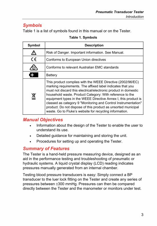
Symbols Table 1 is a list of symbols found in this manual or on the Tester.
Table 1. Symbols
Symbol Description
Risk of Danger. Important information. See Manual.
Conforms to European Union directives
Conforms to relevant Australian EMC standards
Battery
This product complies with the WEEE Directive (2002/96/EC) marking requirements. The affixed label indicates that you must not discard this electrical/electronic product in domestic household waste. Product Category: With reference to the equipment types in the WEEE Directive Annex I, this product is classed as category 9 "Monitoring and Control Instrumentation" product. Do not dispose of this product as unsorted municipal waste. Go to Fluke’s website for recycling information.
Manual Objectives • Information about the design of the Tester to enable the user to
understand its use.
• Detailed guidance for maintaining and storing the unit.
• Procedures for setting up and operating the Tester.
Summary of Features The Tester is a hand-held pressure measuring device, designed as an aid in the performance testing and troubleshooting of pneumatic or hydraulic systems. A liquid crystal display (LCD) reading indicates pressures manually generated from an internal chamber.
Testing blood pressure transducers is easy: Simply connect a BP transducer to the luer lock fitting on the Tester and create any series of pressures between ±300 mmHg. Pressures can then be compared directly between the Tester and the manometer or monitors under test.
DPM1B Operators Manual
4
The Tester has the following features:
• Easy-to-read liquid crystal display (LCD)
• Capable of measuring and generating positive and negative pressures
• Lightweight and portable
• Operates with air or liquid
• An easily accessible knob for zeroing the unit
• LO BAT displayed on the LCD when the battery is low. The battery can be accessed and replaced externally
Applications Many hospital and laboratory instruments measure pressure for diagnostic purposes. Mercury and water manometers, sphygmomanometers, and blood pressure monitors are some of these devices. Maintenance and calibration of these instruments requires a device capable of both generating and measuring pressure. The Tester was designed to fit this requirement, particularly in the area of blood pressure transducers.
The Tester was designed to improve and simplify the measurements necessary for determining the accuracy of any direct blood pressure monitoring system. Vacuum (negative) and positive pressures from −300 mmHg to +300 mmHg can be generated within the Tester and applied to a system under test. The pressure delivered by the pneumatic transducer tester is indicated on a liquid crystal display for quick comparison to the monitor.
The accuracy of mercury or water manometers can be verified with the Tester. Pressures can be applied simultaneously to the manometer to be tested and the Tester using a Y-connector. Pressure is applied to the system as normal, usually with a squeeze bulb. The results can be compared between the Tester and the manometer under test.
Testing Capabilities Verifying the proper operation of a blood pressure transducer can be a tedious and time-consuming task. Usually a mercury or water manometer is used to generate known values of pressure while the transducer's response is monitored. A malfunctioning transducer shows up when comparing the output of the manometer versus the output of

Pneumatic Transducer Tester Specifications
5
the transducer. Unfortunately, manometers can add significant errors themselves, because of the difficulty in interpreting the liquid level in the column. This affects the calibration of and subsequent determination of the liquid height.
The critical nature of invasive blood pressure measurement requires a properly calibrated monitoring system capable of linear operation over a wide range of pressure levels. Pressures at the catheter tip should be accurately transmitted through the connective tubing and stopcocks to the transducer-sensing diaphragm. In a properly operating system, distention of the diaphragm will generate an output voltage proportional to the applied pressure. Occasionally, one or more of the elements involved in this process will malfunction causing inaccurate indications of blood pressure on the monitor. Very often these errors can be attributed to a transducer with a nonlinear response or shifted sensitivity.
Specifications Pressure Measurement Range ............................ ±300 mmHg
Pressure Generation Range ................................ ±300 mmHg
Altitude .................................................................. Up to 2000 m
Humidity ................................................................ 80 % relative humidity up to 31 °C (88 °F), decreasing linearly to 50 % relative humidity at 40 °C (104 °F)
IP Rating ................................................................ IEC 60529: IP40
Safety ..................................................................... IEC 61010-1: Pollution Degree 2
Accuracy ................................................................ ±1 % of reading or ±1 mmHg (Whichever is greater)
Temperature Performance
Operating ............................................................ 10 °C to 40 °C 50 °F to 104 °F
Storage ............................................................... -20 °C to 60 °C -4 °F to 140 °F
Overpressure ........................................................ Not to exceed 1000 mmHg
Voltage Requirements .......................................... One 9 V alkaline battery
Battery Life ............................................................ 60 hours continuous use
Display ................................................................... 0.5 in (1.3 cm) LCD with LO BAT indicator
Dimensions ........................................................... 5.8 in x 3.6 in x 1.5 in (14.6 cm x 15.9 cm x 3.8 cm)
Weight .................................................................... 10 oz. (260 g)

DPM1B Operators Manual
6
Electromagnetic Compatibility (EMC) International ........................................................ IEC 61326-1: Portable
CISPR 11: Group 1, Class A Group 1: Equipment has intentionally generated and/or uses conductively-coupled radio frequency energy that is necessary for the internal function of the equipment itself. Class A: Equipment is suitable for use in all establishments other than domestic and those directly connected to a low-voltage power supply network that supplies buildings used for domestic purposes. There may be potential difficulties in ensuring electromagnetic compatibility in other environments due to conducted and radiated disturbances. Emissions that exceed the levels required by CISPR 11 can occur when the equipment is connected to a test object.
USA (FCC) .......................................................... 47 CFR 15 subpart B
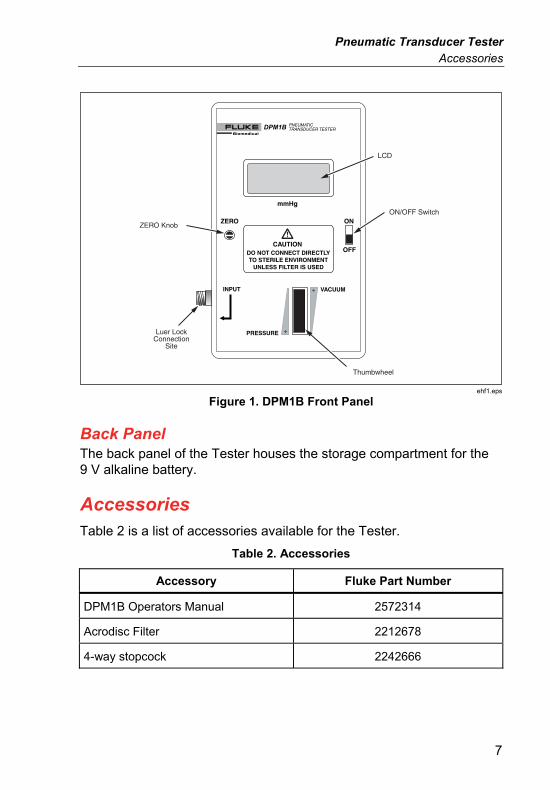
Tester Familiarization The Tester incorporates a highly accurate digital pressure meter and pneumatic pressure-generating cylinder into a small, hand-held package for determining the accuracy of most blood pressure measurement systems.
Front Panel The Tester incorporates a specially designed pressure cylinder and precise solid-state transducer for generating and measuring static pressure from −300 mmHg to +300 mmHg. The following items are identified in Figure 1:
• ON/OFF Switch: Used to power the Tester.
• Thumbwheel: Used to regulate the pressure and pressure value displayed on the LCD.
• Luer Lock: Built-in to provide the external connection for stopcocks or pressure fittings.
• ZERO Knob: Adjusts LCD reading to zero.
• Liquid Crystal Display (LCD): Illuminated when the Tester is -powered. Displays LO BAT when the battery is low.
Note
When the Tester is first powered ON, the display may take a few seconds to settle to zero.
Pneumatic Transducer Tester Accessories
7
ON/OFF Switch
Thumbwheel
LCD
Luer LockConnection
Site
ZERO Knob
ehf1.eps
Figure 1. DPM1B Front Panel
Back Panel The back panel of the Tester houses the storage compartment for the 9 V alkaline battery.
Accessories Table 2 is a list of accessories available for the Tester.
Table 2. Accessories
Accessory Fluke Part Number
DPM1B Operators Manual 2572314
Acrodisc Filter 2212678
4-way stopcock 2242666
DPM1B Operators Manual
8
Operation Overview When operating according to the instructions given in this section, the Tester produces and displays a pressure for comparison to the displayed pressure on the monitor the blood pressure transducer under test is connected to. A conversion table is found in Multiplication Factors section that quickly provides the multiplication factors to compare various units of measure.
Operating the DPM1B Occasionally a blood pressure transducer under test may not have the sensitivity specified by the manufacturer of the monitor the transducer under test is connected to. By matching gain adjustments on the monitor, deviations in sensitivity can usually be compensated for. A transducer that is not performing as specified, however, could have other problems, and sensitivity measurements can be an early indication of performance deterioration.
Setup 1. Connect the Tester transducer, monitor, and 2 stopcocks as
shown in Figure 2.
Note
The stopcock connecting the Tester to the transducer is used to vent the system to the atmosphere. The other stopcock is used to fill the transducer dome with liquid.
2. Ensure that the testing medium is homogeneous before beginning any test. The transducer testing can be accomplished using either an air or liquid-fill system.
Note
Do not mix air and liquid in any part of the system; inaccurate readings could result.
Caution
To avoid possible damage to the Tester:
• Do not connect Tester to a sterile environment unless a new sterile filter is used.
• Do not allow any liquid into the pressure port of the transducer. Use the provided filter between the Tester and liquid.

Pneumatic Transducer Tester Operation Overview
9
PneumaticTransducer
Tester
BP Input
Filter
Monitor
2
1
ehf2.eps
Figure 2. DPM1B to Monitor Setup
3. When the system is to be filled with liquid, position Stopcock 1 as shown in Figure 2.
4. Attach a liquid-filled syringe to the top port of Stopcock 2.
5. Position the valve on Stopcock 2 so that the syringe can be used to fill the system with liquids. (Turn the valve on the stopcock so that the two opposing end arrows point straight up and down and the middle arrow points toward the Tester, as depicted in Figure 2.)
6. After filling the system, position both Stopcocks as shown in Figure 2.
7. Remove syringe from top part of Stopcock 2.
Proceed to the section labeled Zeroing the Monitor and Tester.
Zeroing the Monitor and Tester Properly zeroing the measurement system is important to accurately determine transducer sensitivity.
1. Position the valve on Stopcock 1 as shown in Figure 4.
2. Press the ZERO or BALANCE control on the monitor.
3. Turn the Tester ON using the ON/OFF switch on the front panel.
DPM1B Operators Manual
10
Note
Allow approximately 3 minutes warm-up time before taking readings; this allows the electronics to stabilize in the Tester.
4. Zero the Tester by turning the ZERO knob on the front panel of the Tester (See Figure 1 for location of ZERO knob).
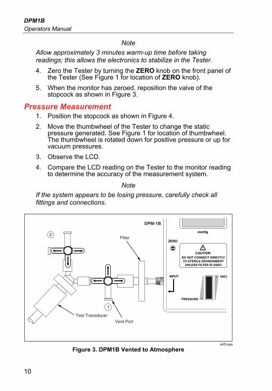
5. When the monitor has zeroed, reposition the valve of the stopcock as shown in Figure 3.
Pressure Measurement 1. Position the stopcock as shown in Figure 4.
2. Move the thumbwheel of the Tester to change the static pressure generated. See Figure 1 for location of thumbwheel. The thumbwheel is rotated down for positive pressure or up for vacuum pressures.
3. Observe the LCD.
4. Compare the LCD reading on the Tester to the monitor reading to determine the accuracy of the measurement system.
Note
If the system appears to be losing pressure, carefully check all fittings and connections.
DPM-1B
Filter2
1
Test TransducerVent Port
ehf3.eps
Figure 3. DPM1B Vented to Atmosphere
Pneumatic Transducer Tester Testing Transducer Linearity
11
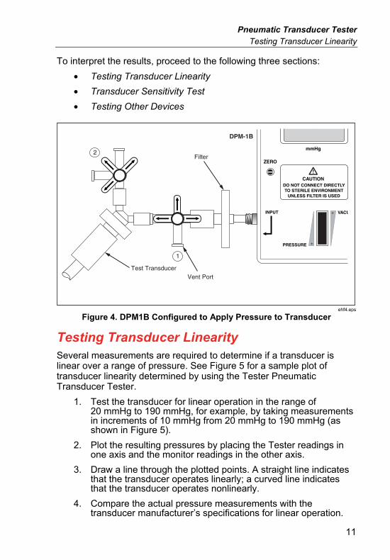
To interpret the results, proceed to the following three sections:
• Testing Transducer Linearity
• Transducer Sensitivity Test
• Testing Other Devices
DPM-1B
Filter2
1
Test TransducerVent Port
ehf4.eps
Figure 4. DPM1B Configured to Apply Pressure to Transducer
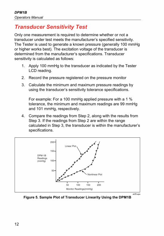
Testing Transducer Linearity Several measurements are required to determine if a transducer is linear over a range of pressure. See Figure 5 for a sample plot of transducer linearity determined by using the Tester Pneumatic Transducer Tester.
1. Test the transducer for linear operation in the range of 20 mmHg to 190 mmHg, for example, by taking measurements in increments of 10 mmHg from 20 mmHg to 190 mmHg (as shown in Figure 5).
2. Plot the resulting pressures by placing the Tester readings in one axis and the monitor readings in the other axis.
3. Draw a line through the plotted points. A straight line indicates that the transducer operates linearly; a curved line indicates that the transducer operates nonlinearly.
4. Compare the actual pressure measurements with the transducer manufacturer’s specifications for linear operation.
DPM1B Operators Manual
12
Transducer Sensitivity Test Only one measurement is required to determine whether or not a transducer under test meets the manufacturer’s specified sensitivity. The Tester is used to generate a known pressure (generally 100 mmHg or higher works best). The excitation voltage of the transducer is determined from the manufacturer’s specifications. Transducer sensitivity is calculated as follows:
1. Apply 100 mmHg to the transducer as indicated by the Tester LCD reading.
2. Record the pressure registered on the pressure monitor
3. Calculate the minimum and maximum pressure readings by using the transducer’s sensitivity tolerance specifications. For example: For a 100 mmHg applied pressure with a 1 % tolerance, the minimum and maximum readings are 99 mmHg and 101 mmHg, respectively.
4. Compare the readings from Step 2, along with the results from Step 3. If the readings from Step 2 are within the range calculated in Step 3, the transducer is within the manufacturer’s specifications.
Linear Plot
Nonlinear Plot
200
150
DPM-1BReadings(mmHg)
Monitor Readings(mmHg)
100
50
50 100 150 200
ehf5.eps
Figure 5. Sample Plot of Transducer Linearity Using the DPM1B

Pneumatic Transducer Tester Testing Other Devices
13
Testing Other Devices A variety of pressure-measuring and pressure-generating devices can be tested using the Tester. The Tester can be used as a pressure standard to easily test water manometers, mercury manometers, and sphygmomanometers.
Set up the system as described in the section titled Pressure Measurement. Substitute the system to be tested for the transducer.
Use the Tester to measure pressure only. The Tester is not designed to generate the high pressures required by some of these instruments.
Multiplication Factors Table 3. Multiplication Factors
PSI
lb/in2
In Hg
@0 °C
In H20
@20 °CmmHg
@0 °C
mm H20
@4 °C ATM TORR
PSI
lb/in2
1
0.49118
3.6062×10⁻²
1.9337×10⁻²
1.4223×10⁻³
14.696
1.9337 ×10⁻²
In Hg @0 °C
2.0359
1
7.3419×10⁻²
3.9368×10⁻²
2.8959 ×10⁻³
29.920
3.9368 ×10⁻²
In H20 @20 °C
27.73
13.620
1
0.53622
3.9440 ×10⁻²
407.52
0.53622
mmHg @0 °C
51.714
25.401
1.8649
1
7.3558 ×10⁻²
760.00
1
mm H20 @4 °C
703.05
345.32
25.353
13.595
1
1.0332
×104
13.595
ATM
6.8045 ×10⁻²
3.3422×10⁻²
2.4538×10⁻³
1.3158 ×10⁻³
9.6788 ×10⁻⁵
1
1.3158 ×10⁻³
TORR
51.714
25.401
1.8649
1
7.3558 ×10⁻²
760.00
1
from
to
DPM1B Operators Manual
14
Maintenance Warning
For safe operation and maintenance of the product and to prevent possible electrical shock, fire, or personal injury:
• Repair the Product before use if the battery leaks.
• Be sure that the battery polarity is correct to prevent battery leakage.
• The battery contains hazardous chemicals that can cause burns or explode. If exposure to chemicals occurs, clean with water and get medical aid.
• Do not disassemble the battery.
• Do not disassemble or crush battery cells and battery packs.
• Do not put battery cells and battery packs near heat or fire. Do not put in sunlight.
• Do not short the battery terminals together.
• Do not keep cells or battery in a container where the terminals can be shorted.
• Remove the input signals before you clean the Product.
• Use only specified replacement parts.
• Have an approved technician repair the Product.
Cleaning Outside Surfaces The DPM1B outside surfaces can be cleaned with a cloth dampened with water and mild detergent or alcohol.
Battery Replacement The battery compartment of the Tester is found in the rear panel of the tester. Slide the compartment cover to expose the battery holder. Replace with one 9 V alkaline battery.