
Fisher 546 Electro-Pneumatic Transducer...Instruction Manual D200108X012 546 Transducer March 2015 2...
24
www.Fisher.com Fisherr 546 Electro‐Pneumatic Transducer Contents Introduction 1 ................................. Scope of Manual 1 ............................. Description 3 ................................. Specifications 4 ............................... Educational Services 4 ......................... Installation 5 .................................. Mounting 5 .................................. Pressure Connections 5 ........................ Diagnostic Connections 6 ...................... Electrical Connections 6 ........................ Operating Information 7 ......................... Adjustments 8 ................................ Calibration 8 ................................. Equipment Required 8 ...................... Calibration Procedure 9 ..................... Recalibration 10 ........................... Changing Output Pressure Range 10 ............. Reversing the Action 10 ........................ Split Range Operation 11 ....................... Principle of Operation 11 ........................ Maintenance 13 ................................ Relay Removal and Replacement 14 .............. Replacing the Feedback Bellows Assembly 14 ...... Troubleshooting 14 ............................ Electrical 14 .............................. Pneumatic 15 ............................. Alignment 15 ................................. Span Adjustment 15 ....................... Torque Motor Frame 16 .................... Armature Travel Stop 16 .................... Coil 16 ................................... Figure 1. Fisher 546 Electro‐Pneumatic Transducer Mounted on a 657 Pneumatic Diaphragm Actuator W2115 546 FILTER REGULATOR Parts Ordering 16 ............................... Parts List 17 ................................... Repair Kits 17 ................................. Transducers 17 ............................... Torque Motor 18 .............................. Mounting Parts 20 ............................. Diagnostic Connections 22 ..................... Introduction Scope of Manual This instruction manual provides installation, operation, maintenance, and parts ordering information for Fisher 546 transducers and the 82 relay. Refer to separate manuals for instructions covering equipment used with the transducer. Do not install, operate or maintain a 546 transducer without being fully trained and qualified in valve, actuator and accessory installation, operation and maintenance. To avoid personal injury or property damage it is important to carefully read, understand, and follow all of the contents of this manual, including all safety cautions and warnings. If you have any questions about these instructions, contact your Emerson Process Management sales office before proceeding. Instruction Manual D200108X012 546 Transducer March 2015
Transcript of Fisher 546 Electro-Pneumatic Transducer...Instruction Manual D200108X012 546 Transducer March 2015 2...
www.Fisher.com
Fisher� 546 Electro‐Pneumatic Transducer
ContentsIntroduction 1. . . . . . . . . . . . . . . . . . . . . . . . . . . . . . . . .
Scope of Manual 1. . . . . . . . . . . . . . . . . . . . . . . . . . . . .Description 3. . . . . . . . . . . . . . . . . . . . . . . . . . . . . . . . .Specifications 4. . . . . . . . . . . . . . . . . . . . . . . . . . . . . . .Educational Services 4. . . . . . . . . . . . . . . . . . . . . . . . .
Installation 5. . . . . . . . . . . . . . . . . . . . . . . . . . . . . . . . . .Mounting 5. . . . . . . . . . . . . . . . . . . . . . . . . . . . . . . . . .Pressure Connections 5. . . . . . . . . . . . . . . . . . . . . . . .Diagnostic Connections 6. . . . . . . . . . . . . . . . . . . . . .Electrical Connections 6. . . . . . . . . . . . . . . . . . . . . . . .
Operating Information 7. . . . . . . . . . . . . . . . . . . . . . . . .Adjustments 8. . . . . . . . . . . . . . . . . . . . . . . . . . . . . . . .Calibration 8. . . . . . . . . . . . . . . . . . . . . . . . . . . . . . . . .
Equipment Required 8. . . . . . . . . . . . . . . . . . . . . .Calibration Procedure 9. . . . . . . . . . . . . . . . . . . . .Recalibration 10. . . . . . . . . . . . . . . . . . . . . . . . . . .
Changing Output Pressure Range 10. . . . . . . . . . . . .Reversing the Action 10. . . . . . . . . . . . . . . . . . . . . . . .Split Range Operation 11. . . . . . . . . . . . . . . . . . . . . . .
Principle of Operation 11. . . . . . . . . . . . . . . . . . . . . . . .Maintenance 13. . . . . . . . . . . . . . . . . . . . . . . . . . . . . . . .
Relay Removal and Replacement 14. . . . . . . . . . . . . .Replacing the Feedback Bellows Assembly 14. . . . . .Troubleshooting 14. . . . . . . . . . . . . . . . . . . . . . . . . . . .
Electrical 14. . . . . . . . . . . . . . . . . . . . . . . . . . . . . .Pneumatic 15. . . . . . . . . . . . . . . . . . . . . . . . . . . . .
Alignment 15. . . . . . . . . . . . . . . . . . . . . . . . . . . . . . . . .Span Adjustment 15. . . . . . . . . . . . . . . . . . . . . . .Torque Motor Frame 16. . . . . . . . . . . . . . . . . . . .Armature Travel Stop 16. . . . . . . . . . . . . . . . . . . .Coil 16. . . . . . . . . . . . . . . . . . . . . . . . . . . . . . . . . . .
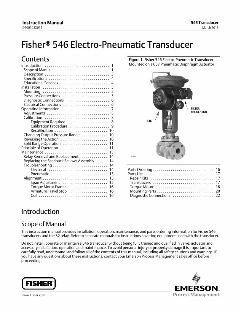
Figure 1. Fisher 546 Electro‐Pneumatic TransducerMounted on a 657 Pneumatic Diaphragm Actuator
W2115
546
FILTERREGULATOR
Parts Ordering 16. . . . . . . . . . . . . . . . . . . . . . . . . . . . . . .Parts List 17. . . . . . . . . . . . . . . . . . . . . . . . . . . . . . . . . . .
Repair Kits 17. . . . . . . . . . . . . . . . . . . . . . . . . . . . . . . . .Transducers 17. . . . . . . . . . . . . . . . . . . . . . . . . . . . . . .Torque Motor 18. . . . . . . . . . . . . . . . . . . . . . . . . . . . . .Mounting Parts 20. . . . . . . . . . . . . . . . . . . . . . . . . . . . .Diagnostic Connections 22. . . . . . . . . . . . . . . . . . . . .
Introduction
Scope of ManualThis instruction manual provides installation, operation, maintenance, and parts ordering information for Fisher 546transducers and the 82 relay. Refer to separate manuals for instructions covering equipment used with the transducer.
Do not install, operate or maintain a 546 transducer without being fully trained and qualified in valve, actuator andaccessory installation, operation and maintenance. To avoid personal injury or property damage it is important tocarefully read, understand, and follow all of the contents of this manual, including all safety cautions and warnings. Ifyou have any questions about these instructions, contact your Emerson Process Management sales office beforeproceeding.
Instruction ManualD200108X012
546 TransducerMarch 2015
Instruction ManualD200108X012
546 TransducerMarch 2015
2
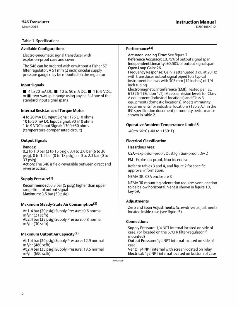
Table 1. Specifications
Available Configurations
Electro‐pneumatic signal transducer withexplosion‐proof case and cover
The 546 can be ordered with or without a Fisher 67filter regulator. A 51 mm (2 inch) circular supplypressure gauge may be mounted on the regulator.
Input Signals
� 4 to 20 mA DC, � 10 to 50 mA DC, � 1 to 9 VDC,or � two‐way split range using any half of one of thestandard input signal spans
Internal Resistance of Torque Motor
4 to 20 mA DC Input Signal: 176 ±10 ohms10 to 50 mA DC Input Signal: 90 ±10 ohms1 to 9 VDC Input Signal: 1300 ±50 ohms(temperature‐compensated circuit)
Output Signals
Ranges:0.2 to 1.0 bar (3 to 15 psig), 0.4 to 2.0 bar (6 to 30psig), 0 to 1.2 bar (0 to 18 psig), or 0 to 2.3 bar (0 to33 psig)Action: The 546 is field‐reversible between direct andreverse action.
Supply Pressure(1)
Recommended: 0.3 bar (5 psig) higher than upperrange limit of output signalMaximum: 3.5 bar (50 psig)
Maximum Steady‐State Air Consumption(2)
At 1.4 bar (20 psig) Supply Pressure: 0.6 normalm3/hr (21 scfh)At 2.4 bar (35 psig) Supply Pressure: 0.8 normalm3/hr (30 scfh)
Maximum Output Air Capacity(2)
At 1.4 bar (20 psig) Supply Pressure: 12.9 normalm3/hr (480 scfh)At 2.4 bar (35 psig) Supply Pressure: 18.5 normalm3/hr (690 scfh)
Performance(3)
Actuator Loading Time: See figure 7Reference Accuracy: ±0.75% of output signal spanIndependent Linearity: ±0.50% of output signal spanOpen Loop Gain: 26Frequency Response: Gain is attenuated 3 dB at 20 Hzwith transducer output signal piped to a typicalinstrument bellows with 305 mm (12 inches) of 1/4inch tubingElectromagnetic Interference (EMI): Tested per IEC61326‐1 (Edition 1.1). Meets emission levels for ClassA equipment (industrial locations) and Class Bequipment (domestic locations). Meets immunityrequirements for industrial locations (Table A.1 in theIEC specification document). Immunity performanceshown in table 2.
Operative Ambient Temperature Limits(1)
-40 to 66�C (-40 to +150�F)
Electrical Classification
Hazardous Area:
CSA—Explosion-proof, Dust Ignition‐proof, Div 2
FM—Explosion‐proof, Non‐incendive
Refer to tables 3 and 4, and figure 2 for specificapproval information.
NEMA 3R, CSA enclosure 3
NEMA 3R mounting orientation requires vent locationto be below horizontal. Vent is shown in figure 10,key 69.
Adjustments
Zero and Span Adjustments: Screwdriver adjustmentslocated inside case (see figure 5)
Connections
Supply Pressure: 1/4 NPT internal located on side ofcase, (or located on the 67CFR filter‐regulator ifmounted)Output Pressure: 1/4 NPT internal located on side ofcaseVent: 1/4 NPT internal with screen located on relayElectrical: 1/2 NPT internal located on bottom of case
-continued-
Instruction ManualD200108X012
546 TransducerMarch 2015
3
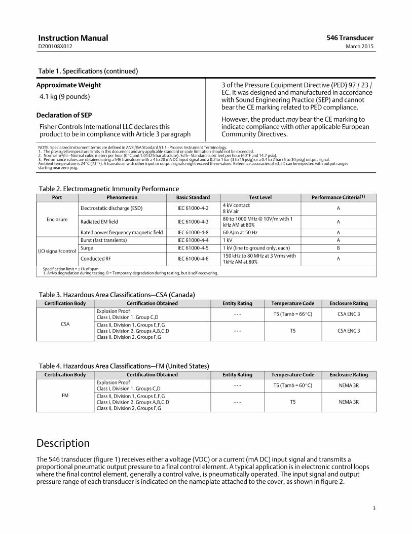
Table 1. Specifications (continued)
Approximate Weight
4.1 kg (9 pounds)
Declaration of SEP
Fisher Controls International LLC declares thisproduct to be in compliance with Article 3 paragraph
3 of the Pressure Equipment Directive (PED) 97 / 23 /EC. It was designed and manufactured in accordancewith Sound Engineering Practice (SEP) and cannotbear the CE marking related to PED compliance.
However, the product may bear the CE marking toindicate compliance with other applicable EuropeanCommunity Directives.
NOTE: Specialized instrument terms are defined in ANSI/ISA Standard 51.1 - Process Instrument Terminology.1. The pressure/temperature limits in this document and any applicable standard or code limitation should not be exceeded.2. Normal m3/hr—Normal cubic meters per hour (0�C and 1.01325 bar absolute). Scfh—Standard cubic feet per hour (60�F and 14.7 psia).3. Performance values are obtained using a 546 transducer with a 4 to 20 mA DC input signal and a 0.2 to 1 bar (3 to 15 psig) or a 0.4 to 2 bar (6 to 30 psig) output signal.Ambient temperature is 24�C (73�F). A transducer with other input or output signals might exceed these values. Reference accuracies of ±3.5% can be expected with output rangesstarting near zero psig.
Table 2. Electromagnetic Immunity PerformancePort Phenomenon Basic Standard Test Level Performance Criteria(1)
Enclosure
Electrostatic discharge (ESD) IEC 61000‐4‐24 kV contact8 kV air
A
Radiated EM field IEC 61000‐4‐380 to 1000 MHz @ 10V/m with 1kHz AM at 80%
A
Rated power frequency magnetic field IEC 61000‐4‐8 60 A/m at 50 Hz A
I/O signal/control
Burst (fast transients) IEC 61000‐4‐4 1 kV A
Surge IEC 61000‐4‐5 1 kV (line to ground only, each) B
Conducted RF IEC 61000‐4‐6150 kHz to 80 MHz at 3 Vrms with1kHz AM at 80%
A
Specification limit = ±1% of span1. A=No degradation during testing. B = Temporary degradation during testing, but is self‐recovering.
Table 3. Hazardous Area Classifications—CSA (Canada)Certification Body Certification Obtained Entity Rating Temperature Code Enclosure Rating
CSA
Explosion ProofClass I, Division 1, Group C,D
- - - T5 (Tamb = 66�C) CSA ENC 3
Class II, Division 1, Groups E,F,GClass I, Division 2, Groups A,B,C,DClass II, Division 2, Groups F,G
- - - T5 CSA ENC 3
Table 4. Hazardous Area Classifications—FM (United States)Certification Body Certification Obtained Entity Rating Temperature Code Enclosure Rating
FM
Explosion ProofClass I, Division 1, Groups C,D
- - - T5 (Tamb = 60�C) NEMA 3R
Class II, Division 1, Groups E,F,GClass I, Division 2, Groups A,B,C,DClass II, Division 2, Groups F,G
- - - T5 NEMA 3R
Description
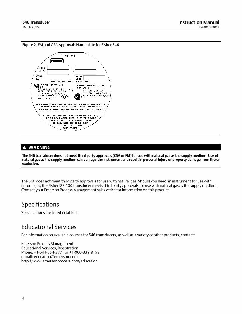
The 546 transducer (figure 1) receives either a voltage (VDC) or a current (mA DC) input signal and transmits aproportional pneumatic output pressure to a final control element. A typical application is in electronic control loopswhere the final control element, generally a control valve, is pneumatically operated. The input signal and outputpressure range of each transducer is indicated on the nameplate attached to the cover, as shown in figure 2.
Instruction ManualD200108X012
546 TransducerMarch 2015
4
Figure 2. FM and CSA Approvals Nameplate for Fisher 546
WARNING
The 546 transducer does not meet third party approvals (CSA or FM) for use with natural gas as the supply medium. Use ofnatural gas as the supply medium can damage the instrument and result in personal injury or property damage from fire orexplosion.
The 546 does not meet third party approvals for use with natural gas. Should you need an instrument for use withnatural gas, the Fisher i2P‐100 transducer meets third party approvals for use with natural gas as the supply medium.Contact your Emerson Process Management sales office for information on this product.
SpecificationsSpecifications are listed in table 1.
Educational ServicesFor information on available courses for 546 transducers, as well as a variety of other products, contact:
Emerson Process ManagementEducational Services, RegistrationPhone: +1-641-754-3771 or +1-800-338-8158 e‐mail: [email protected]://www.emersonprocess.com/education
Instruction ManualD200108X012
546 TransducerMarch 2015
5
Installation
WARNING
Avoid personal injury from sudden release of process pressure. Before mounting the controller:
� Always wear protective clothing, gloves, and eyewear when performing any installation operations to avoid personalinjury.
� Check with your process or safety engineer for any additional measures that must be taken to protect against processmedia.
� If installing into an existing application, also refer to the WARNING at the beginning of the Maintenance section in thisinstruction manual.
MountingWhen a 546 transducer is ordered as part of a control valve assembly, the factory mounts the transducer on theactuator and connects the necessary tubing, then adjusts the transducer as specified on the order.
Transducers also can be ordered separately for mounting on a control valve assembly already in service. Thetransducer may be ordered with or without mounting parts. Mounting parts include the appropriate bracket and boltsfor attaching the unit to an actuator boss (with tapped holes) or for attaching it to the diaphragm casing. If preferred,mounting parts are available for mounting the transducer on a 51 mm (2 inch) diameter pipestand, a flat surface, or abulkhead.
Tubing is not included if the transducer is not factory mounted. Use 9.5 mm (3/8‐inch) outside diameter tubing for allsupply and output connections. Tubing length between the transducer output and the final control element should beas short as possible to minimize its effect on control loop stability.
Pressure Connections
WARNING
Severe personal injury or property damage may occur if the instrument air supply is not clean, dry and oil‐free. While useand regular maintenance of a filter that removes particles larger than 40 micrometers in diameter will suffice in mostapplications, check with an Emerson Process Management field office and industry instrument air quality standards for usewith corrosive air or if you are unsure about the proper amount or method of air filtration or filter maintenance.
Note
The supply source must be clean, dry, oil‐free, non‐corrosive air at an unfailing pressure at least 0.3 bar (5 psig) higher than theupper limit of the transducer output pressure range. This means that for an output pressure range of 0.2 to 1.0 bar (3 to 15 psig)the supply pressure should be at least 1.4 bar (20 psig); for a 0.4 to 2.0 bar (6 to 30 psig) range, the supply pressure should be atleast 2.4 bar (35 psig). The supply pressure to the filter regulator should not be more than 17.3 bar (250 psig) at a maximumtemperature of 66�C (150�F).
Instruction ManualD200108X012
546 TransducerMarch 2015
6
If specified, the filter regulator is mounted on the transducer case. A pressure gauge on the regulator shows the supplypressure to the transducer.
1. Connect a supply pressure source to the 1/4 NPT IN connection on the filter regulator (if furnished) or to the 1/4NPT SUPPLY connection on the transducer case (if a regulator is not furnished).
2. Run 9.5 mm (3/8‐inch) outside diameter tubing from the 1/4 NPT OUTPUT connection on the transducer case tothe input connection on the pneumatic actuator or valve positioner. This connection is made at the factory if theunit is shipped mounted on an actuator as shown in figure 1.
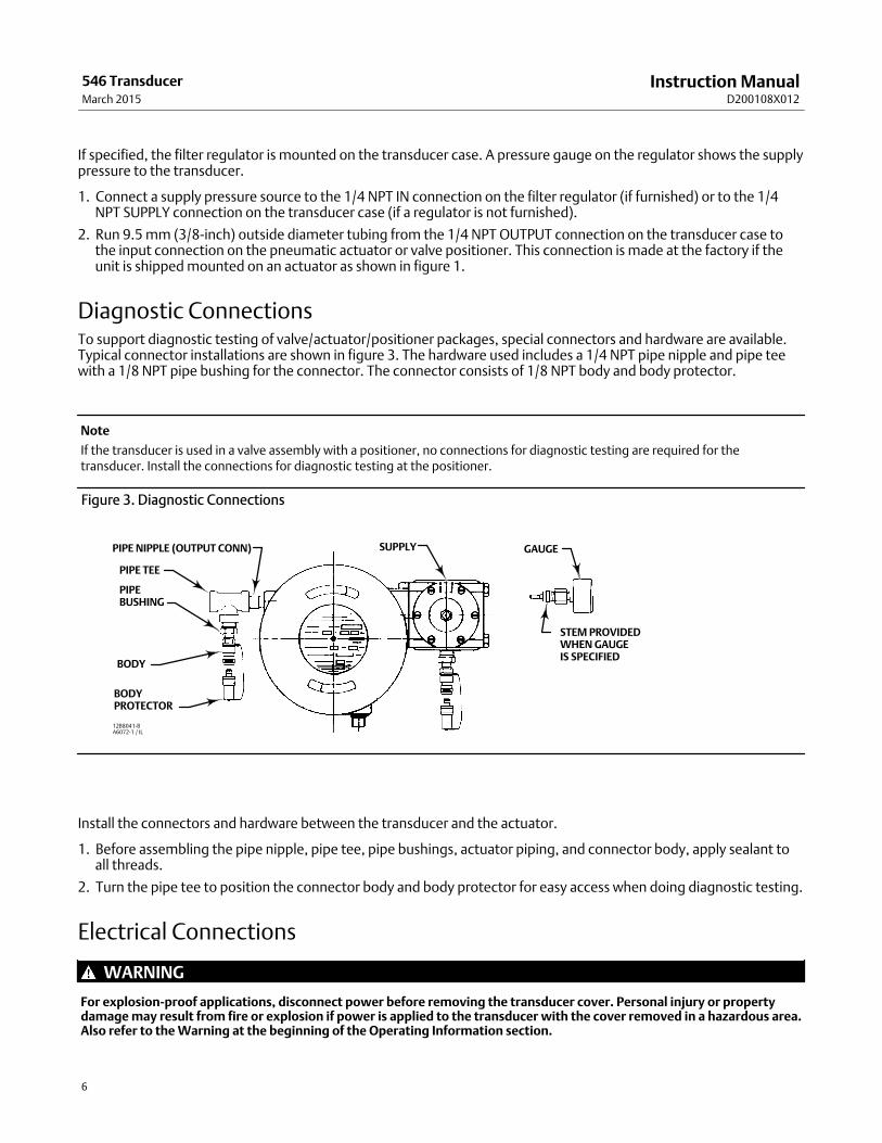
Diagnostic ConnectionsTo support diagnostic testing of valve/actuator/positioner packages, special connectors and hardware are available.Typical connector installations are shown in figure 3. The hardware used includes a 1/4 NPT pipe nipple and pipe teewith a 1/8 NPT pipe bushing for the connector. The connector consists of 1/8 NPT body and body protector.
Note
If the transducer is used in a valve assembly with a positioner, no connections for diagnostic testing are required for thetransducer. Install the connections for diagnostic testing at the positioner.
Figure 3. Diagnostic Connections
PIPE NIPPLE (OUTPUT CONN)
12B8041‐BA6072‐1 / IL
PIPE TEE
PIPEBUSHING
BODY
BODYPROTECTOR
SUPPLY GAUGE
STEM PROVIDEDWHEN GAUGEIS SPECIFIED
Install the connectors and hardware between the transducer and the actuator.
1. Before assembling the pipe nipple, pipe tee, pipe bushings, actuator piping, and connector body, apply sealant toall threads.
2. Turn the pipe tee to position the connector body and body protector for easy access when doing diagnostic testing.
Electrical Connections
WARNING
For explosion‐proof applications, disconnect power before removing the transducer cover. Personal injury or propertydamage may result from fire or explosion if power is applied to the transducer with the cover removed in a hazardous area.Also refer to the Warning at the beginning of the Operating Information section.
Instruction ManualD200108X012
546 TransducerMarch 2015
7
For explosion‐proof applications, install rigid metal conduit and a conduit seal no more than 457 mm (18 inches) from thetransducer. Personal injury or property damage may result from explosion if the seal is not installed.
Select wiring and/or cable glands that are rated for the environment of use (such as hazardous area, ingress protection, andtemperature). Failure to use properly rated wiring and/or cable glands can result in personal injury or property damagefrom fire or explosion.
Wiring connections must be in accordance with local, regional, and national codes for any given hazardous are approval.Failure to follow the local, regional, and national codes could result in personal injury or property damage from fire orexplosion.
The electrical connections are made in the transducer case. A 1/2 NPT conduit connection is provided in the bottom ofthe case. Use a suitable conduit seal for hazardous locations. The wires that carry the input signal from the controldevice are connected to the terminal mounting bracket assembly (key 53, figure 9).
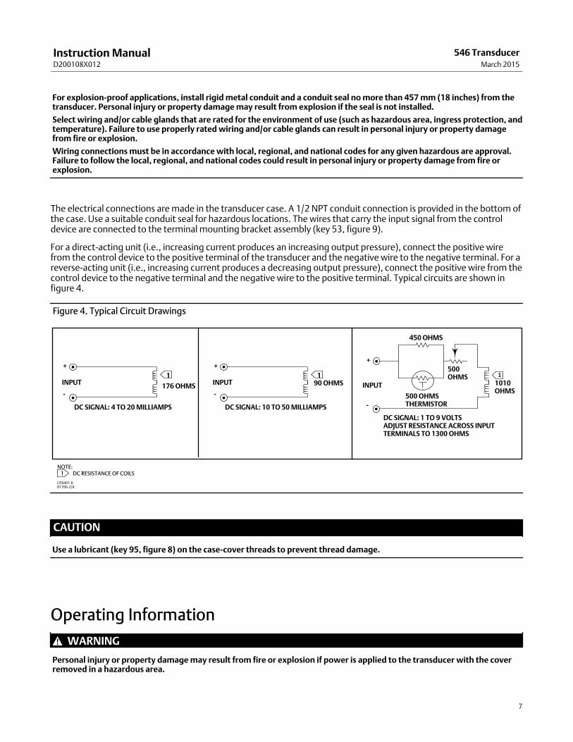
For a direct‐acting unit (i.e., increasing current produces an increasing output pressure), connect the positive wirefrom the control device to the positive terminal of the transducer and the negative wire to the negative terminal. For areverse‐acting unit (i.e., increasing current produces a decreasing output pressure), connect the positive wire from thecontrol device to the negative terminal and the negative wire to the positive terminal. Typical circuits are shown infigure 4.
Figure 4. Typical Circuit Drawings
DC SIGNAL: 1 TO 9 VOLTSADJUST RESISTANCE ACROSS INPUTTERMINALS TO 1300 OHMS
1
+
-176 OHMS
DC SIGNAL: 4 TO 20 MILLIAMPS
INPUT1
+
-
90 OHMS
DC SIGNAL: 10 TO 50 MILLIAMPS
INPUT
NOTE: 1 DC RESISTANCE OF COILS
1
+
-
1010OHMS
INPUT
500 OHMSTHERMISTOR
450 OHMS
500OHMS
CP8401‐BB1766‐2/IL
CAUTION
Use a lubricant (key 95, figure 8) on the case‐cover threads to prevent thread damage.
Operating Information
WARNING
Personal injury or property damage may result from fire or explosion if power is applied to the transducer with the coverremoved in a hazardous area.
Instruction ManualD200108X012
546 TransducerMarch 2015
8
If the transducer is installed in an application where explosion‐proof classification is required, perform the following steps(prior to removal of the transducer cover) when any procedure in this section requires removal of the cover:
� Disconnect the electrical signal from the transducer.
� Remove the transducer to a non‐hazardous area.
� Perform procedures as described in this section.
� Reinstall the transducer, and ensure the cover is secured before turning on the electrical signal.
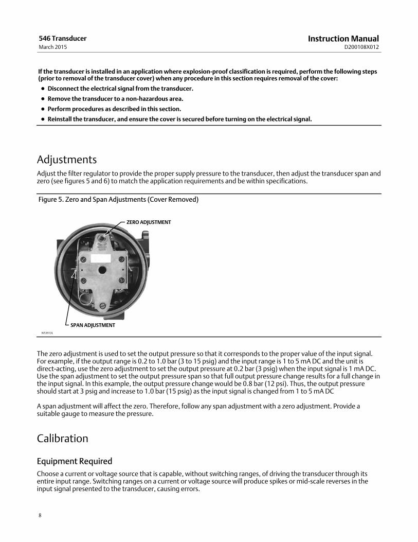
AdjustmentsAdjust the filter regulator to provide the proper supply pressure to the transducer, then adjust the transducer span andzero (see figures 5 and 6) to match the application requirements and be within specifications.
Figure 5. Zero and Span Adjustments (Cover Removed)
W5391/IL
ZERO ADJUSTMENT
SPAN ADJUSTMENT
The zero adjustment is used to set the output pressure so that it corresponds to the proper value of the input signal.For example, if the output range is 0.2 to 1.0 bar (3 to 15 psig) and the input range is 1 to 5 mA DC and the unit isdirect‐acting, use the zero adjustment to set the output pressure at 0.2 bar (3 psig) when the input signal is 1 mA DC.Use the span adjustment to set the output pressure span so that full output pressure change results for a full change inthe input signal. In this example, the output pressure change would be 0.8 bar (12 psi). Thus, the output pressureshould start at 3 psig and increase to 1.0 bar (15 psig) as the input signal is changed from 1 to 5 mA DC
A span adjustment will affect the zero. Therefore, follow any span adjustment with a zero adjustment. Provide asuitable gauge to measure the pressure.
Calibration
Equipment Required
Choose a current or voltage source that is capable, without switching ranges, of driving the transducer through itsentire input range. Switching ranges on a current or voltage source will produce spikes or mid‐scale reverses in theinput signal presented to the transducer, causing errors.
Instruction ManualD200108X012
546 TransducerMarch 2015
9
Calibration Procedure
Note
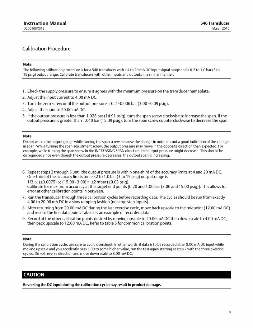
The following calibration procedure is for a 546 transducer with a 4 to 20 mA DC input signal range and a 0.2 to 1.0 bar (3 to 15 psig) output range. Calibrate transducers with other inputs and outputs in a similar manner.
1. Check the supply pressure to ensure it agrees with the minimum pressure on the transducer nameplate.
2. Adjust the input current to 4.00 mA DC.
3. Turn the zero screw until the output pressure is 0.2 ±0.006 bar (3.00 ±0.09 psig).
4. Adjust the input to 20.00 mA DC.
5. If the output pressure is less than 1.028 bar (14.91 psig), turn the span screw clockwise to increase the span. If theoutput pressure is greater than 1.040 bar (15.09 psig), turn the span screw counterclockwise to decrease the span.
Note
Do not watch the output gauge while turning the span screw because the change in output is not a good indication of the changein span. While turning the span adjustment screw, the output pressure may move in the opposite direction than expected. Forexample, while turning the span screw in the INCREASING SPAN direction, the output pressure might decrease. This should bedisregarded since even though the output pressure decreases, the output span is increasing.
6. Repeat steps 2 through 5 until the output pressure is within one‐third of the accuracy limits at 4 and 20 mA DC.One‐third of the accuracy limits for a 0.2 to 1.0 bar (3 to 15 psig) output range is
1/3 � (±0.0075) � (15.00 - 3.00) = ±2 mbar (±0.03 psig).Calibrate for maximum accuracy at the target end points [0.20 and 1.00 bar (3.00 and 15.00 psig)]. This allows forerror at other calibration points in between.
7. Run the transducer through three calibration cycles before recording data. The cycles should be run from exactly4.00 to 20.00 mA DC in a slow ramping fashion (no large step inputs).
8. After returning from 20.00 mA DC during the last exercise cycle, move back upscale to the midpoint (12.00 mA DC)and record the first data point. Table 5 is an example of recorded data.
9. Record at the other calibration points desired by moving upscale to 20.00 mA DC then down scale to 4.00 mA DC,then back upscale to 12.00 mA DC. Refer to table 5 for common calibration points.
Note
During the calibration cycle, use care to avoid overshoot. In other words, if data is to be recorded at an 8.00 mA DC input whilemoving upscale and you accidently pass 8.00 to some higher value, run the test again starting at step 7 with the three exercisecycles. Do not reverse direction and move down scale to 8.00 mA DC.
CAUTION
Reversing the DC input during the calibration cycle may result in product damage.
Instruction ManualD200108X012
546 TransducerMarch 2015
10
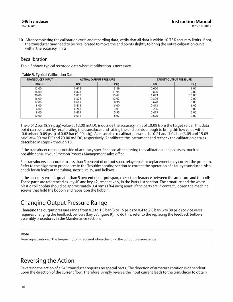
10. After completing the calibration cycle and recording data, verify that all data is within ±0.75% accuracy limits. If not,the transducer may need to be recalibrated to move the end points slightly to bring the entire calibration curvewithin the accuracy limits.
Recalibration
Table 5 shows typical recorded data where recalibration is necessary.
Table 5. Typical Calibration DataTRANSDUCER INPUT ACTUAL OUTPUT PRESSURE TARGET OUTPUT PRESSURE
mA DC Bar Psig Bar Psig
12.0016.0020.0016.0012.00
8.004.008.00
12.00
0.6120.8231.0350.8280.6170.4130.2070.4090.618
8.8911.9515.0212.02
8.966.003.015.958.97
0.6200.8261.0330.8260.6200.4130.2060.4130.620
9.0012.0015.0012.00
9.006.003.006.009.00
The 0.612 bar (8.89 psig) value at 12.00 mA DC is outside the accuracy limit of ±0.09 from the target value. This datapoint can be raised by recalibrating the transducer and raising the end points enough to bring this low value within-0.6 mbar (-0.09 psig) of 0.62 bar (9.00 psig). A reasonable recalibration would be 0.21 and 1.04 bar (3.05 and 15.05psig) at 4.00 mA DC and 20.00 mA DC, respectively. Recalibrate the instrument and recheck the calibration data asdescribed in steps 7 through 10.
If the transducer remains outside of accuracy specifications after altering the calibration end points as much aspossible consult your Emerson Process Management sales office.
For transducers inaccurate to less than 5 percent of output span, relay repair or replacement may correct the problem.Refer to the alignment procedures in the Troubleshooting section to correct the operation of a faulty transducer. Alsocheck for air leaks at the tubing, nozzle, relay, and bellows.
If the accuracy error is greater than 5 percent of output span, check the clearance between the armature and the coils.These parts are referenced as key 40 and key 42, respectively, in the Parts List section. The armature and the whiteplastic coil bobbin should be approximately 0.4 mm (1/64 inch) apart. If the parts are in contact, loosen the machinescrews that hold the bobbin and reposition the bobbin.
Changing Output Pressure RangeChanging the output pressure range from 0.2 to 1.0 bar (3 to 15 psig) to 0.4 to 2.0 bar (6 to 30 psig) or vice versarequires changing the feedback bellows (key 57, figure 9). To do this, refer to the replacing the feedback bellowsassembly procedures in the Maintenance section.
Note
Re‐magnetization of the torque motor is required when changing the output pressure range.
Reversing the ActionReversing the action of a 546 transducer requires no special parts. The direction of armature rotation is dependentupon the direction of the current flow. Therefore, simply reverse the input current leads to the transducer to obtain
Instruction ManualD200108X012
546 TransducerMarch 2015
11
the opposite action. Whenever the action is changed, readjust the zero of the transducer as outlined in theadjustments procedures.
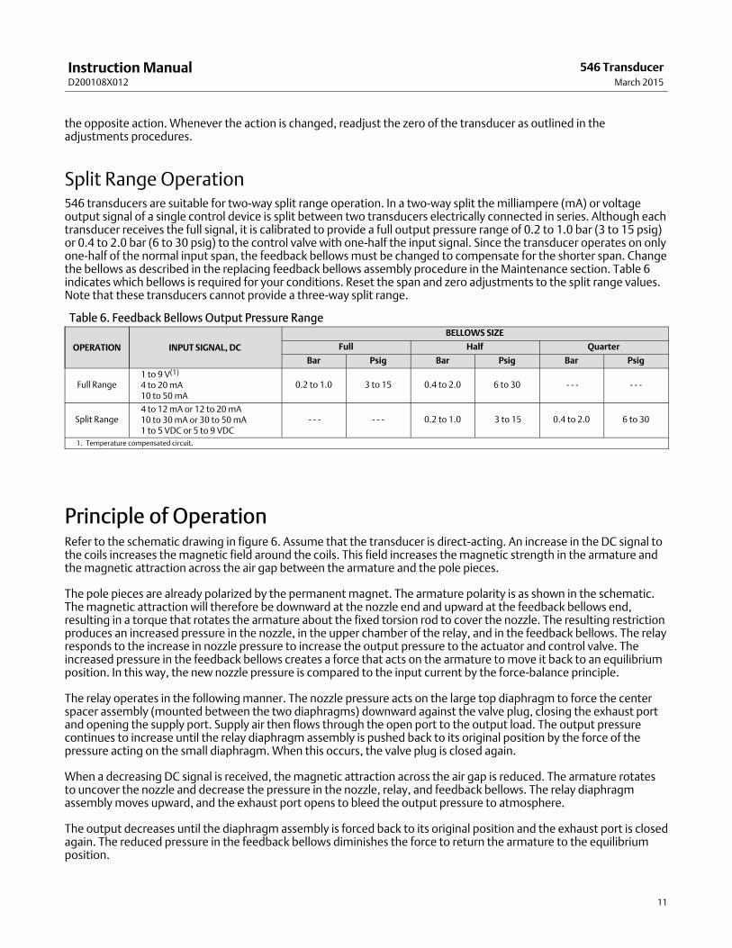
Split Range Operation546 transducers are suitable for two‐way split range operation. In a two‐way split the milliampere (mA) or voltageoutput signal of a single control device is split between two transducers electrically connected in series. Although eachtransducer receives the full signal, it is calibrated to provide a full output pressure range of 0.2 to 1.0 bar (3 to 15 psig)or 0.4 to 2.0 bar (6 to 30 psig) to the control valve with one‐half the input signal. Since the transducer operates on onlyone‐half of the normal input span, the feedback bellows must be changed to compensate for the shorter span. Changethe bellows as described in the replacing feedback bellows assembly procedure in the Maintenance section. Table 6indicates which bellows is required for your conditions. Reset the span and zero adjustments to the split range values.Note that these transducers cannot provide a three‐way split range.
Table 6. Feedback Bellows Output Pressure Range
OPERATION INPUT SIGNAL, DC
BELLOWS SIZE
Full Half Quarter
Bar Psig Bar Psig Bar Psig
Full Range1 to 9 V(1)
4 to 20 mA10 to 50 mA
0.2 to 1.0 3 to 15 0.4 to 2.0 6 to 30 - - - - - -
Split Range4 to 12 mA or 12 to 20 mA10 to 30 mA or 30 to 50 mA1 to 5 VDC or 5 to 9 VDC
- - - - - - 0.2 to 1.0 3 to 15 0.4 to 2.0 6 to 30
1. Temperature compensated circuit.
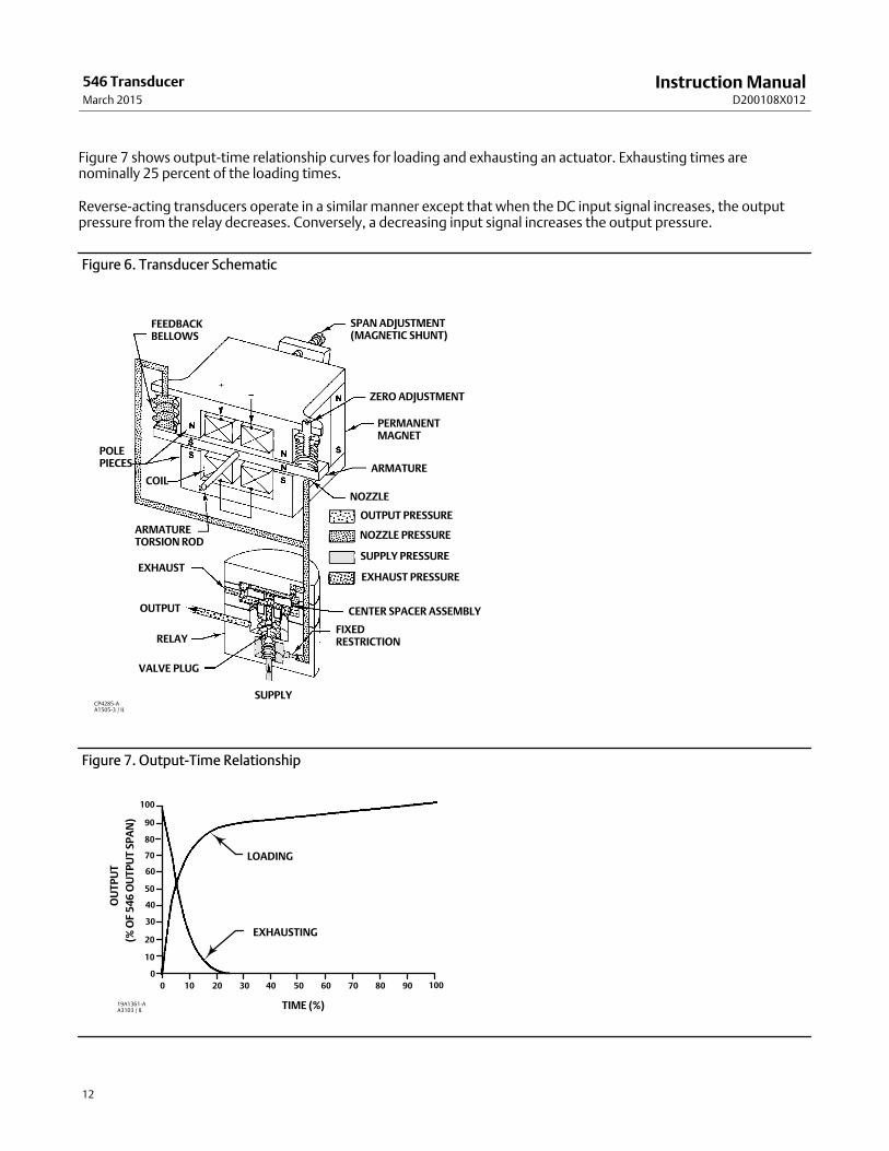
Principle of OperationRefer to the schematic drawing in figure 6. Assume that the transducer is direct‐acting. An increase in the DC signal tothe coils increases the magnetic field around the coils. This field increases the magnetic strength in the armature andthe magnetic attraction across the air gap between the armature and the pole pieces.
The pole pieces are already polarized by the permanent magnet. The armature polarity is as shown in the schematic.The magnetic attraction will therefore be downward at the nozzle end and upward at the feedback bellows end,resulting in a torque that rotates the armature about the fixed torsion rod to cover the nozzle. The resulting restrictionproduces an increased pressure in the nozzle, in the upper chamber of the relay, and in the feedback bellows. The relayresponds to the increase in nozzle pressure to increase the output pressure to the actuator and control valve. Theincreased pressure in the feedback bellows creates a force that acts on the armature to move it back to an equilibriumposition. In this way, the new nozzle pressure is compared to the input current by the force‐balance principle.
The relay operates in the following manner. The nozzle pressure acts on the large top diaphragm to force the centerspacer assembly (mounted between the two diaphragms) downward against the valve plug, closing the exhaust portand opening the supply port. Supply air then flows through the open port to the output load. The output pressurecontinues to increase until the relay diaphragm assembly is pushed back to its original position by the force of thepressure acting on the small diaphragm. When this occurs, the valve plug is closed again.
When a decreasing DC signal is received, the magnetic attraction across the air gap is reduced. The armature rotatesto uncover the nozzle and decrease the pressure in the nozzle, relay, and feedback bellows. The relay diaphragmassembly moves upward, and the exhaust port opens to bleed the output pressure to atmosphere.
The output decreases until the diaphragm assembly is forced back to its original position and the exhaust port is closedagain. The reduced pressure in the feedback bellows diminishes the force to return the armature to the equilibriumposition.
Instruction ManualD200108X012
546 TransducerMarch 2015
12
Figure 7 shows output‐time relationship curves for loading and exhausting an actuator. Exhausting times arenominally 25 percent of the loading times.
Reverse‐acting transducers operate in a similar manner except that when the DC input signal increases, the outputpressure from the relay decreases. Conversely, a decreasing input signal increases the output pressure.
Figure 6. Transducer Schematic
FEEDBACKBELLOWS
POLEPIECES
COIL
ARMATURETORSION ROD
EXHAUST
OUTPUT
RELAY
VALVE PLUG
SUPPLY
FIXEDRESTRICTION
CENTER SPACER ASSEMBLY
EXHAUST PRESSURE
SUPPLY PRESSURE
NOZZLE PRESSURE
OUTPUT PRESSURE
NOZZLE
ARMATURE
PERMANENTMAGNET
ZERO ADJUSTMENT
SPAN ADJUSTMENT(MAGNETIC SHUNT)
CP4285-AA1505-3 / IL
Figure 7. Output‐Time Relationship
LOADING
EXHAUSTING
TIME (%)
0 10 20 30 40 50 60 70 80 90 100
0
10
20
30
40
50
60
70
80
90
100
OU
TP
UT
19A1361‐AA3103 / IL
(% O
F 5
46
OU
TP
UT
SP
AN
)
Instruction ManualD200108X012
546 TransducerMarch 2015
13
MaintenanceMaintenance of the transducer consists of relay repair or replacement, and replacement of the feedback bellows.
WARNING
The following maintenance procedures require that the transducer be taken out of service. This requires that certainprecautions be taken to avoid personal injury or equipment damage caused by sudden release of pressure. Prior tomaintenance:
� Always wear protective clothing, gloves, and eyewear when performing any maintenance procedures to avoid personalinjury.
� Disconnect electrical power before removing the transducer cover.
� Shut off or disconnect pressure lines to the transducer.
� Disconnect any operating lines providing air pressure, electrical power, or a control signal to the actuator. Be sure theactuator cannot suddenly open or close the valve.
� Use bypass valves or completely shut off the process to isolate the valve from process pressure.
� Do not remove the actuator from the valve while the valve is still pressurized.
� Relieve process pressure on both sides of the valve.
� Vent the power actuator loading pressure and relieve any actuator spring precompression.
� Use lock‐out procedures to be sure that the above measures stay in effect while you work on the equipment.
� Check with your process or safety engineer for any additional measures that must be taken to protect against processmedia.
WARNING
For explosion proof applications, disconnect power before opening the transducer cover. Personal injury or propertydamage may result from fire or explosion if power is not disconnected.
CAUTION
The presence of Emerson Process Management personnel and also approval agency personnel may be required if youservice (other than normal, routine maintenance, such as calibration) or replace components on a transducer that carries athird‐party approval. When you replace components, use only components specified by the factory. Substitution withother components may void the third‐party approval. Also, always use proper component replacement techniques, aspresented in this manual. Improper techniques can cause poor quality repairs and impair the safety features of the device.
Figure 9 shows the torque motor and associated parts. Shaded key numbers indicate parts that should not bedisassembled from the torque motor because the magnetism in the torque motor magnets will decreasepermanently.
Certain troubleshooting and alignment procedures are described at the end of this section. These may serve as a guideto correct some problems. Improper supply pressure and mechanical defects in pneumatic and electrical connectionsshould be apparent upon inspection and repaired as appropriate.
Instruction ManualD200108X012
546 TransducerMarch 2015
14
CAUTION
Never disassemble the torque motor assembly because the magnetism in the torque motor magnets will decreasepermanently. Shaded key numbers indicate parts that should not be disassembled from the torque motor (see figure 9). Iftroubleshooting or alignment attempts indicate either a faulty torque motor or the necessity of disassembling the torquemotor consult your Emerson Process Management sales office.
Relay Removal and ReplacementUse the following procedure when removing and replacing a relay assembly. Refer to figure 10 for key numberlocations, unless otherwise directed.
1. Loosen the two mounting screws (key 68), and remove the relay assembly from the transducer case (key 1, figure 8).
2. To install the replacement relay assembly, install the two relay mounting screws (key 68) into the relay assembly.Apply lubricant (key 96) to the O‐rings, and make sure the O‐rings (keys 72, 73, and 74) are in place on the relayassembly.
3. Install the relay assembly on the transducer case. Tighten the mounting screws.
4. With the torque motor installed, apply supply pressure to the transducer case, and check the relay assembly forleaks with a soap solution.
Replacing the Feedback Bellows AssemblyRefer to figure 9 for key number locations.
1. Loosen the hex nut (key 31).
2. Remove the bellows screw (key 56) and O‐ring (key 36) under the head of the bellows screw.
3. Pull the bellows assembly (key 57) out. The armature is slotted to allow removal of the bellows assembly.
4. Inspect and, if necessary, replace the two O‐rings (key 36). Make sure the O‐rings under the bellows assembly are inplace.
5. Choose the correct bellows assembly as outlined in table 6. Install the new bellows assembly. Make sure that theO‐ring (key 36) is in place.
6. Install the bellows screw and O‐ring, and tighten the screw. Be sure the bellows assembly is not distorted in anydirection. Tighten the hex nut (key 31).
7. Refer to the adjusting zero and span procedures in the Adjustments section.
TroubleshootingThis section contains some checks for operational difficulties that may be encountered. If correcting the difficulties isnot possible, contact your Emerson Process Management sales office or service center.
Electrical1. Check the output of the control device. Make sure that it is reaching the transducer.
2. Check the DC input signal. It should be the same as the range stamped on the transducer nameplate.
3. Check the resistance of the transducer circuit to see that it coincides with the value listed on the circuitidentification tag located on the torque motor.
Instruction ManualD200108X012
546 TransducerMarch 2015
15
4. Check the terminal lugs for proper connections. If reverse action of the transducer is observed, simply reverse theinput leads as indicated in the Reversing the Action procedures in the Operating Information section.
Pneumatic
CAUTION
Do not attempt to remove the nozzle (key 19, figure 9) for any reason. Nozzle removal requires disassembling the torquemotor. Disassembling the torque motor will permanently reduce the strength of the magnets, causing improper operation.Also, do not adjust the baffle (key 18, figure 9). The spacing between the baffle and nozzle is preset and locked at thefactory to obtain optimum performance of the transducer.
1. Connect supply pressure and a pressure gauge to monitor the output. Check the operation of the transducer asfollows:
a. Force the baffle (key 18, figure 9) against the nozzle. The output pressure should build up to approximately thesupply pressure. If it does not, check for a leak in the pneumatic system or a burr on the nozzle.
b. Force the baffle away from the nozzle. The output pressure should drop to less than 0.07 bar (1 psig). If it doesnot, check the flame arrestors in the transducer case (see figure 8). If the flame arrestors require cleaning, firstremove the torque motor assembly from the case by removing four machine screws (key 9, figure 8). Then, cleanthe flame arrestors by blowing them out with air pressure.
2. Check zero and span adjustment for proper setting. Refer to the adjustments procedure.
3. Check the supply pressure. It should be at least 0.3 bar (5 psig) above the upper limit of the output pressure range.
4. Check the filter regulator for moisture in the dripwell. Drain off any moisture, and clean the filter element ifnecessary.
5. If the transducer cycles, be sure there are no sharp bends in the copper capillary feedback tubing (key 56, figure 9)and that the tubing is not plugged.
6. Check the nozzle. If it is clogged, remove the entire torque motor assembly from the case by removing fourmachine screws (key 9, figure 8). Run a wire through the nozzle from the underside of the assembly.
7. Erratic operation may be caused by metal chips in the air gap between the armature and the pole pieces. Blow anychips out of the torque motor assembly with low pressure air.
8. If a problem persists, check the relay as described in the Relay Maintenance procedures in this section.
AlignmentThe following alignment procedures can be used in conjunction with troubleshooting procedures to correct theoperation of a faulty transducer.
Span Adjustment
Refer to figure 9 for key number locations, unless otherwise directed.
If setting the required span is not possible, additional span adjustment can be obtained by shifting the entire spanadjustment assembly (key 55) at the flexure pivot end. The alignment procedure is as follows:
1. Shut off the DC input signal and supply pressure to the transducer.
2. Disconnect the external lead wires from the terminal mounting bracket assembly (key 53).
Instruction ManualD200108X012
546 TransducerMarch 2015
16
3. Loosen the four machine screws (key 9, figure 8) that hold the torque motor assembly to the case. Remove theentire torque motor assembly from the case.
4. Loosen the two flexure pivot screws (key 25) that hold the flexure pivot to the torque motor assembly base.
5. Slide the span adjustment assembly in or out as required. Sliding it in toward the base decreases the span; sliding itout away from the base increases the span.
6. Tighten the flexure pivot screws. Replace the torque motor assembly, and tighten the screws (key 9, figure 8). Makesure that the O‐ring (key 37) is in place. Connect the external lead wires, and turn on the air supply.
7. Make final adjustment of the span with the span adjustment screw.
Torque Motor Frame
The top pole piece plate (key 50, figure 9) of the torque motor can become twisted with respect to the bottom polepiece plate (key 51, figure 9). If this happens contact your Emerson Process Management sales office.
Armature Travel Stop
The armature travel stop (key 52, figure 9) must be in place to prevent overstressing the armature and coil support(key 41, figure 9) due to over‐travel. The clearance between the armature and travel stop should be 0.13 mm (0.005 inches).
The two screws at the base of the travel stop can be loosened if an alignment is necessary.
Coil
The coil assembly (key 42, figure 9) consists of a nylon bobbin wound with wire. The coils are not attached to thearmature itself, and therefore, they must not touch the armature, or armature movements will be restricted. If thisproblem exists, loosen the two screws that attach each coil assembly to the armature and coil support. Sight down thearmature and realign the coil assemblies for clearance with the armature. Tighten the screws.
Parts OrderingWhenever corresponding with your sales office about this equipment, mention the serial number of the unit. Thisserial number can be found on the nameplate. When ordering replacement parts, also state the complete11‐character part number of each part needed as found in the following parts list.
Note
In the torque motor assembly drawing (figure 9), there are many shaded key numbers. The shading indicates that these partsshould not be disassembled and that they are not available as individual items. Consequently, no part numbers are shown forthese parts in the Parts List.
WARNING
Use only genuine Fisher replacement parts. Components that are not supplied by Emerson Process Management shouldnot, under any circumstances, be used in any Fisher instrument. The use of components not manufactured by EmersonProcess Management may void your warranty, might adversely affect the performance of the instrument, and could resultin personal injury or property damage.
Instruction ManualD200108X012
546 TransducerMarch 2015
17
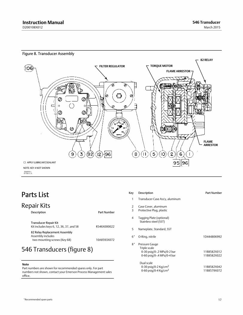
Figure 8. Transducer Assembly
FILTER REGULATOR TORQUE MOTOR
FLAME ARRESTOR
82 RELAY
FLAMEARRESTOR
APPLY LUBRICANT/SEALANT
NOTE: KEY 4 NOT SHOWN
30A8595‐LB1768‐3 / IL
Parts List
Repair KitsDescription Part Number
Transducer Repair Kit
Kit includes keys 6, 12, 36, 37, and 58 R546X000022
82 Relay Replacement Assembly
Assembly includes
two mounting screws (Key 68) 10A8593X072
546 Transducers (figure 8)
Note
Part numbers are shown for recommended spares only. For part
numbers not shown, contact your Emerson Process Management sales
office.
Key Description Part Number
1 Transducer Case Ass'y, aluminum
2 Case Cover, aluminum
3 Protective Plug, plastic
4 Tagging Plate (optional)
Stainless steel (SST)
5 Nameplate, Standard, SST
6* O‐Ring, nitrile 1D444806992
8* Pressure Gauge
Triple scale
0-30 psig/0-.2 MPa/0-2 bar 11B8582X012
0-60 psig/0-.4 MPa/0-4 bar 11B8582X022
Dual scale
0-30 psig/0-2 Kg/cm2 11B8582X042
0-60 psig/0-4 Kg/cm2 11B8579X072
*Recommended spare parts
Instruction ManualD200108X012
546 TransducerMarch 2015
18
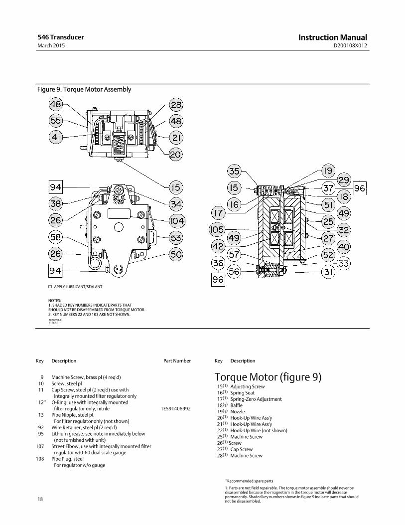
Figure 9. Torque Motor Assembly
30A8594‐KB1767‐3
APPLY LUBRICANT/SEALANT
NOTES:1. SHADED KEY NUMBERS INDICATE PARTS THAT SHOULD NOT BE DISASSEMBLED FROM TORQUE MOTOR.2. KEY NUMBERS 22 AND 103 ARE NOT SHOWN.
Key Description Part Number
9 Machine Screw, brass pl (4 req'd)
10 Screw, steel pl
11 Cap Screw, steel pl (2 req'd) use with
integrally mounted filter regulator only
12* O‐Ring, use with integrally mounted
filter regulator only, nitrile 1E591406992
13 Pipe Nipple, steel pl,
For filter regulator only (not shown)
92 Wire Retainer, steel pl (2 req'd)
95 Lithium grease, see note immediately below
(not furnished with unit)
107 Street Elbow, use with integrally mounted filter
regulator w/0-60 dual scale gauge
108 Pipe Plug, steel
For regulator w/o gauge
Key Description
Torque Motor (figure 9) 15(1) Adjusting Screw
16(1) Spring Seat
17(1) Spring‐Zero Adjustment
18(1) Baffle
19(1) Nozzle
20(1) Hook‐Up Wire Ass'y
21(1) Hook‐Up Wire Ass'y
22(1) Hook‐Up Wire (not shown)
25(1) Machine Screw
26(1) Screw
27(1) Cap Screw
28(1) Machine Screw
*Recommended spare parts
1. Parts are not field repairable. The torque motor assembly should never bedisassembled because the magnetism in the torque motor will decreasepermanently. Shaded key numbers shown in figure 9 indicate parts that shouldnot be disassembled.
Instruction ManualD200108X012
546 TransducerMarch 2015
19
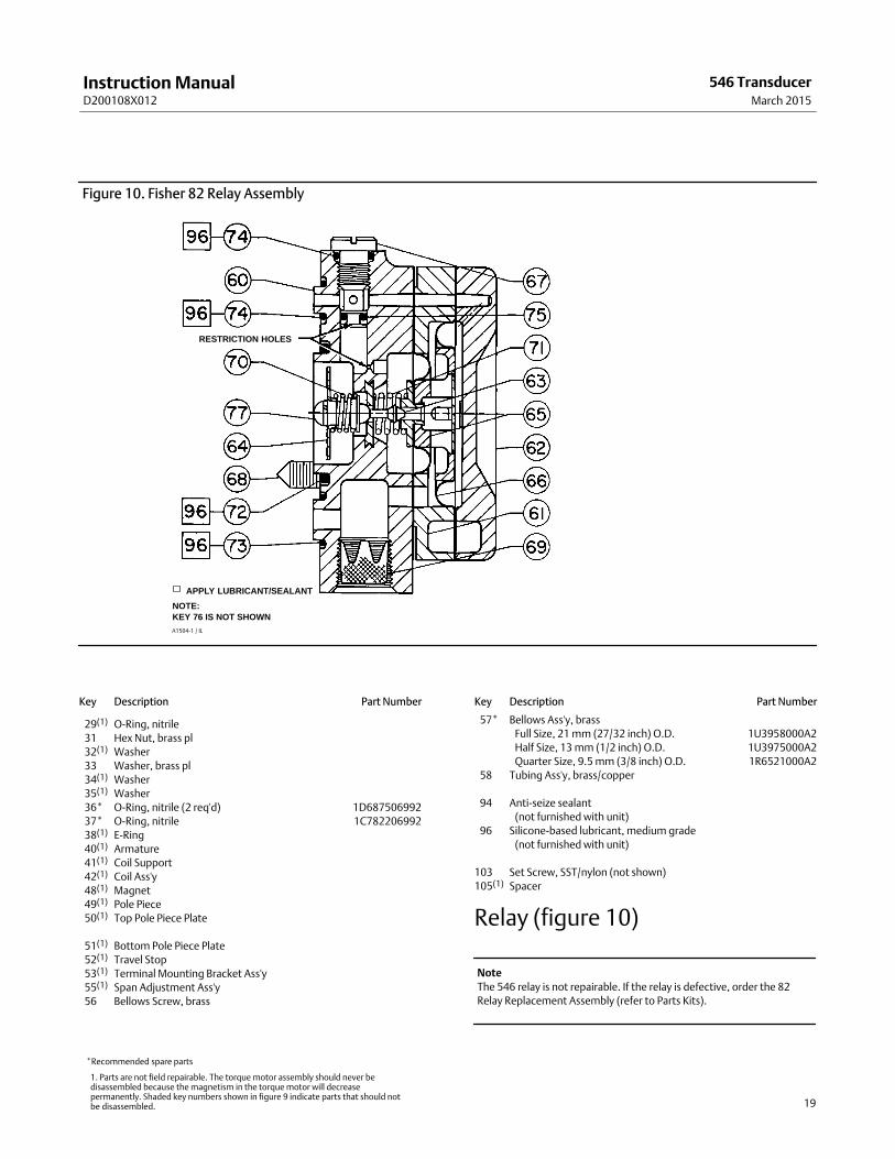
Figure 10. Fisher 82 Relay Assembly
A1504‐1 / IL
NOTE:KEY 76 IS NOT SHOWN
APPLY LUBRICANT/SEALANT
RESTRICTION HOLES
Key Description Part Number
29(1) O‐Ring, nitrile
31 Hex Nut, brass pl
32(1) Washer
33 Washer, brass pl
34(1) Washer
35(1) Washer
36* O‐Ring, nitrile (2 req'd) 1D687506992
37* O‐Ring, nitrile 1C782206992
38(1) E‐Ring
40(1) Armature
41(1) Coil Support
42(1) Coil Ass'y
48(1) Magnet
49(1) Pole Piece
50(1) Top Pole Piece Plate
51(1) Bottom Pole Piece Plate
52(1) Travel Stop
53(1) Terminal Mounting Bracket Ass'y
55(1) Span Adjustment Ass'y
56 Bellows Screw, brass
Key Description Part Number
57* Bellows Ass'y, brass
Full Size, 21 mm (27/32 inch) O.D. 1U3958000A2
Half Size, 13 mm (1/2 inch) O.D. 1U3975000A2
Quarter Size, 9.5 mm (3/8 inch) O.D. 1R6521000A2
58 Tubing Ass'y, brass/copper
94 Anti‐seize sealant
(not furnished with unit)
96 Silicone‐based lubricant, medium grade
(not furnished with unit)
103 Set Screw, SST/nylon (not shown)
105(1) Spacer
Relay (figure 10)
Note
The 546 relay is not repairable. If the relay is defective, order the 82
Relay Replacement Assembly (refer to Parts Kits).
*Recommended spare parts
1. Parts are not field repairable. The torque motor assembly should never bedisassembled because the magnetism in the torque motor will decreasepermanently. Shaded key numbers shown in figure 9 indicate parts that should notbe disassembled.
Instruction ManualD200108X012
546 TransducerMarch 2015
20
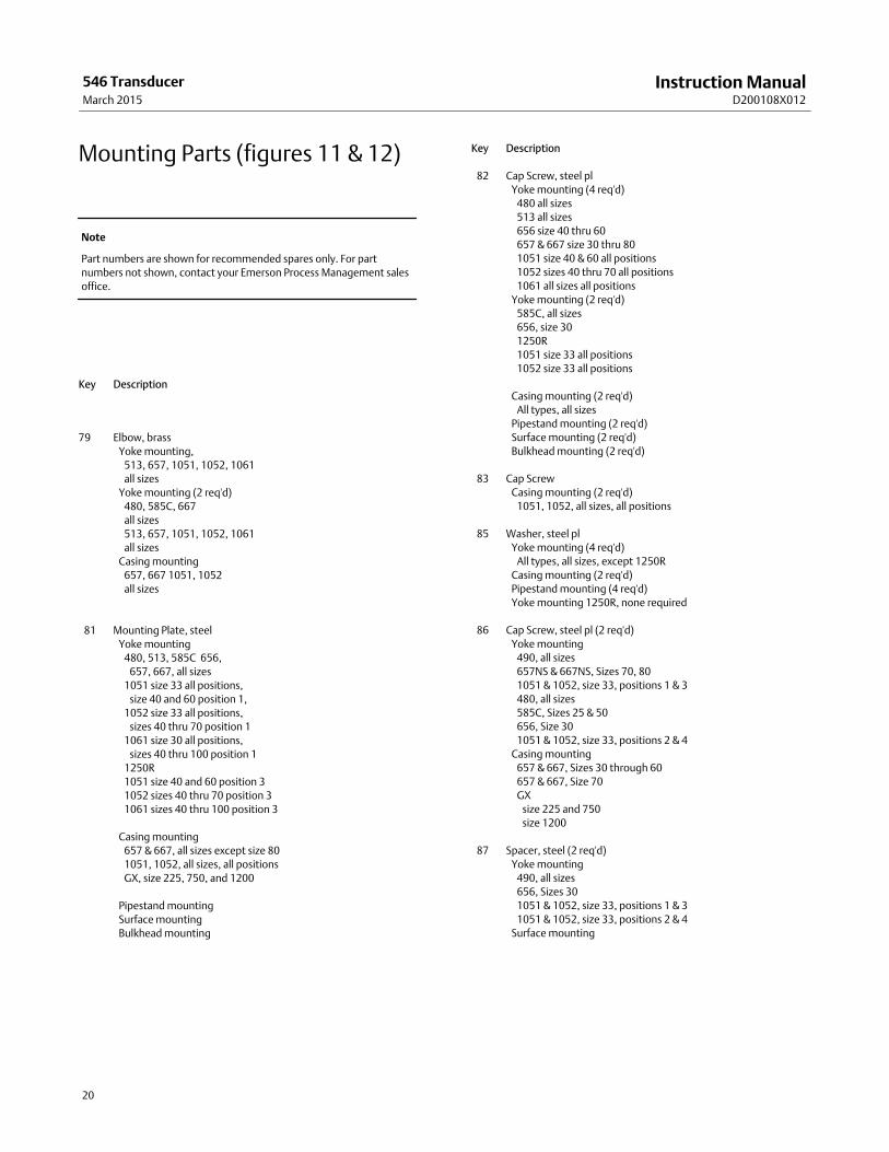
Mounting Parts (figures 11 & 12)
Note
Part numbers are shown for recommended spares only. For part
numbers not shown, contact your Emerson Process Management sales
office.
Key Description
79 Elbow, brass
Yoke mounting,
513, 657, 1051, 1052, 1061
all sizes
Yoke mounting (2 req'd)
480, 585C, 667
all sizes
513, 657, 1051, 1052, 1061
all sizes
Casing mounting
657, 667 1051, 1052
all sizes
81 Mounting Plate, steel
Yoke mounting
480, 513, 585C 656,
657, 667, all sizes
1051 size 33 all positions,
size 40 and 60 position 1,
1052 size 33 all positions,
sizes 40 thru 70 position 1
1061 size 30 all positions,
sizes 40 thru 100 position 1
1250R
1051 size 40 and 60 position 3
1052 sizes 40 thru 70 position 3
1061 sizes 40 thru 100 position 3
Casing mounting
657 & 667, all sizes except size 80
1051, 1052, all sizes, all positions
GX, size 225, 750, and 1200
Pipestand mounting
Surface mounting
Bulkhead mounting
Key Description
82 Cap Screw, steel pl
Yoke mounting (4 req'd)
480 all sizes
513 all sizes
656 size 40 thru 60
657 & 667 size 30 thru 80
1051 size 40 & 60 all positions
1052 sizes 40 thru 70 all positions
1061 all sizes all positions
Yoke mounting (2 req'd)
585C, all sizes
656, size 30
1250R
1051 size 33 all positions
1052 size 33 all positions
Casing mounting (2 req'd)
All types, all sizes
Pipestand mounting (2 req'd)
Surface mounting (2 req'd)
Bulkhead mounting (2 req'd)
83 Cap Screw
Casing mounting (2 req'd)
1051, 1052, all sizes, all positions
85 Washer, steel pl
Yoke mounting (4 req'd)
All types, all sizes, except 1250R
Casing mounting (2 req'd)
Pipestand mounting (4 req'd)
Yoke mounting 1250R, none required
86 Cap Screw, steel pl (2 req'd)
Yoke mounting
490, all sizes
657NS & 667NS, Sizes 70, 80
1051 & 1052, size 33, positions 1 & 3
480, all sizes
585C, Sizes 25 & 50
656, Size 30
1051 & 1052, size 33, positions 2 & 4
Casing mounting
657 & 667, Sizes 30 through 60
657 & 667, Size 70
GX
size 225 and 750
size 1200
87 Spacer, steel (2 req'd)
Yoke mounting
490, all sizes
656, Sizes 30
1051 & 1052, size 33, positions 1 & 3
1051 & 1052, size 33, positions 2 & 4
Surface mounting
Instruction ManualD200108X012
546 TransducerMarch 2015
21
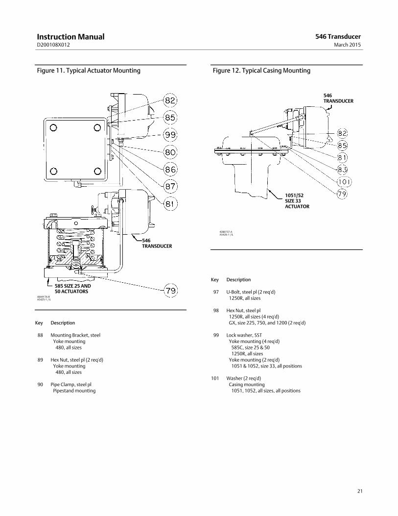
Figure 11. Typical Actuator Mounting
48A9176‐BA5425‐1 / IL
546TRANSDUCER
585 SIZE 25 AND50 ACTUATORS
Key Description
88 Mounting Bracket, steel
Yoke mounting
480, all sizes
89 Hex Nut, steel pl (2 req'd)
Yoke mounting
480, all sizes
90 Pipe Clamp, steel pl
Pipestand mounting
Figure 12. Typical Casing Mounting
42B0737‐AA5426‐1 / IL
546TRANSDUCER
1051/52SIZE 33ACTUATOR
Key Description
97 U‐Bolt, steel pl (2 req'd)
1250R, all sizes
98 Hex Nut, steel pl
1250R, all sizes (4 req'd)
GX, size 225, 750, and 1200 (2 req'd)
99 Lock washer, SST
Yoke mounting (4 req'd)
585C, size 25 & 50
1250R, all sizes
Yoke mounting (2 req'd)
1051 & 1052, size 33, all positions
101 Washer (2 req'd)
Casing mounting
1051, 1052, all sizes, all positions
Instruction ManualD200108X012
546 TransducerMarch 2015
22
Diagnostic Connections
FlowScanner� diagnostic system hook‐up
Includes pipe tee, pipe nipple, pipe bushings,
connector body, and body protector. See figure 3
for part identification.
Note
Part numbers are shown for recommended spares only. For part
numbers not shown, contact your Emerson Process Management sales
office.
If the transducer is used in a valve assembly with a positioner, no
hook‐up for diagnostic testing is required for the transducer. The
hook‐up for diagnostic testing should be installed at the positioner.
Description
For units with gauges
SST fittings
Brass fittings
For units without gauges
SST fittings
Brass fittings

Instruction ManualD200108X012
546 TransducerMarch 2015
23

Instruction ManualD200108X012
546 TransducerMarch 2015
24
Emerson Process Management Marshalltown, Iowa 50158 USASorocaba, 18087 BrazilChatham, Kent ME4 4QZ UKDubai, United Arab EmiratesSingapore 128461 Singapore
www.Fisher.com
The contents of this publication are presented for informational purposes only, and while every effort has been made to ensure their accuracy, they are notto be construed as warranties or guarantees, express or implied, regarding the products or services described herein or their use or applicability. All sales aregoverned by our terms and conditions, which are available upon request. We reserve the right to modify or improve the designs or specifications of suchproducts at any time without notice.
� 1977, 2015 Fisher Controls International LLC. All rights reserved.
Fisher and FlowScanner are marks owned by one of the companies in the Emerson Process Management business unit of Emerson Electric Co. EmersonProcess Management, Emerson, and the Emerson logo are trademarks and service marks of Emerson Electric Co. All other marks are the property of theirrespective owners.
Neither Emerson, Emerson Process Management, nor any of their affiliated entities assumes responsibility for the selection, use or maintenanceof any product. Responsibility for proper selection, use, and maintenance of any product remains solely with the purchaser and end user.