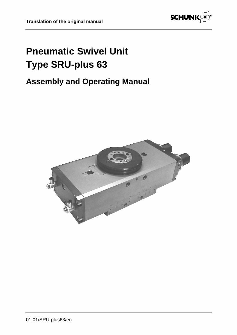
Pneumatic Swivel Unit Type SRU-plus 63
32
Translation of the original manual 01.01/SRU-plus63/en Pneumatic Swivel Unit Type SRU-plus 63 Assembly and Operating Manual
Transcript of Pneumatic Swivel Unit Type SRU-plus 63
Translation of the original manual
01.01/SRU-plus63/en
Pneumatic Swivel Unit
Type SRU-plus 63
Assembly and Operating Manual
2 01.01/SRU-plus63/en
Imprint Copyright: This manual remains the copyrighted property of SCHUNK GmbH & Co. KG. It is solely supplied to our customers and operators of our products and forms part of the module. This documentation may not be duplicated or made accessible to third parties, in par-ticular competitive companies, without our prior permission.
Document ID: 0389445
Technical changes: We reserve the right to make alterations for the purpose of technical improvement.
Edition: 01.01 |08/06/2016|en © SCHUNK GmbH & Co. KG
All rights reserved.
Dear Customer,
Congratulations on choosing a SCHUNK product. By choosing SCHUNK, you have
opted for the highest precision, top quality and best service.
You are going to increase the process reliability of your production and achieve best
machining results – to the customer's complete satisfaction.
SCHUNK products are inspiring.
Our detailed assembly and operation manual will support you.
Do you have further questions? You may contact us at any time – even after purchase.
You can reach us directly at the mentioned addresses in the last chapter of these in-
structions.
Kindest Regards,
Your SCHUNK GmbH & Co. KG
Precision Workholdind Systems
Bahnhofstr. 106 – 134
D-74348 Lauffen/Neckar
Tel. +49-7133-103-2503
Fax +49-7133-103-2189
www.schunk.com

Table of contents
01.01/SRU-plus63/en 3
Table of contents
1 About this manual ................................................................................................. 5
1.1 Purpose/validity .......................................................................................... 5
1.2 Target groups ............................................................................................. 5
1.3 Applicable documents ................................................................................ 5
1.4 Symbols in this manual .............................................................................. 6
2 Basic safety notes ................................................................................................ 7
2.1 Indented use .............................................................................................. 7
2.2 Environmental and operating conditions .................................................... 7
2.3 Controlled production ................................................................................. 8
2.3.1 Protective equipment ..................................................................... 8
2.3.2 Constructional changes, attachments, or modifications ................. 8
2.4 Personnel qualification ............................................................................... 9
2.5 Safety-conscious working........................................................................... 9
2.6 Notes on particular risks ............................................................................. 9
3 Warranty .............................................................................................................. 11
4 Scope of delivery ................................................................................................ 11
5 Accessories ......................................................................................................... 11
5.1 Sensors .................................................................................................... 11
6 Technical Data .................................................................................................... 12
7 Assembly and installation .................................................................................. 13
7.1 Mechanical connection ............................................................................. 13
7.2 Air connection .......................................................................................... 15
7.2.1 Rotary feedthrough ...................................................................... 17
8 Adjustment of the shock absorber stroke ........................................................ 18
9 Setting the speed ................................................................................................ 19
10 Swivel angle adjustment .................................................................................... 20
10.1 Fine adjustment of end positions 0° und 180° .......................................... 20
(See chapter 12 Assembly drawing for sectional view of the position number) .... 20
10.2 Sensors .................................................................................................... 21
10.2.1 Inductive proximity switches IN 80 ............................................... 21
10.2.2 Magnetic switch MMS 30 ............................................................. 24
Table of contents
4 01.01/SRU-plus63/en
11 Maintenance and care ........................................................................................ 25
11.1 Maintenance and lubrication intervals ...................................................... 25
11.2 Lubricants/Lubrication points (basic lubrication) ....................................... 25
11.3 Dismantling the module ............................................................................ 25
11.4 Servicing and assembling the module ...................................................... 26
11.5 Replacing and adjusting the shock absorber............................................ 27
12 Assembly drawing .............................................................................................. 28
13 Spare parts .......................................................................................................... 29
14 Translation of original declaration of incorporation ........................................ 31
About this manual
01.01/SRU-plus63/en 5
1 About this manual
1.1 Purpose/validity
This manual is part of the module and describes the safe
and proper use during all phases of operation.
This manual is valid only for the module specified on the
front page.
1.2 Target groups
Target groups Task
Manufacturer, operator Keep this manual available for the personnel at all times.
Require personnel to read and observe this manual and
the applicable documents, especially the safety notes and
warnings.
Skilled personnel, fitter Read, observe and follow this manual and the applicable
documents, especially the safety notes and warnings.
Tab. 1
1.3 Applicable documents
You can find the following documents on our homepage:
Document Purpose
Calculation program for
gripping modules (SSG)
Selection of the module according to the application.
Avail-able free of charge.
Catalog Technical data or application parameters of the module
and information on accessories. The last version is al-
ways valid.
Assembly and Operating
Manuals for sensors
Detailed information about assembly, adjustment and
commissioning of the sensors.
General terms of business Including notes on the warranty.
Tab. 2
About this manual
6 01.01/SRU-plus63/en
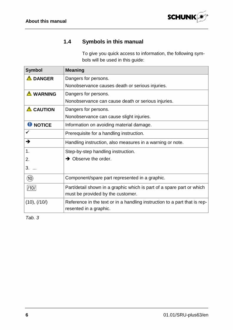
1.4 Symbols in this manual
To give you quick access to information, the following sym-
bols will be used in this guide:
Symbol Meaning
DANGER Dangers for persons.
Nonobservance causes death or serious injuries.
WARNING Dangers for persons.
Nonobservance can cause death or serious injuries.
CAUTION Dangers for persons.
Nonobservance can cause slight injuries.
NOTICE Information on avoiding material damage.
Prerequisite for a handling instruction.
Handling instruction, also measures in a warning or note.
1.
2.
3. ...
Step-by-step handling instruction.
Observe the order.
Component/spare part represented in a graphic.
Part/detail shown in a graphic which is part of a spare part or which
must be provided by the customer.
(10), (/10/) Reference in the text or in a handling instruction to a part that is rep-
resented in a graphic.
Tab. 3
Basic safety notes
01.01/SRU-plus63/en 7
2 Basic safety notes
2.1 Indented use
The module was designed to swivel permissible attach-
ments or workpieces.
The module is intended for installation in a machine. The
requirements of the applicable guidelines must be observed
and complied with.
The module may be used only in the context of its defined
application parameters.
Any other use or use exceeding that specified is an in-
fringement of use for intended purpose. The manufacturer
bears no liability for damage resulting from such use.
2.2 Environmental and operating conditions
The module may be used only in the context of its
defined application parameters (see chapter 6, page 11
and catalog).
Make sure that the environment is clean and the ambient
temperature corresponds to the specifications per the
catalog. Maintenance and lubrication intervals (see
chapter 11.1, page 25).
Make sure that the environment is free from splash
water and vapors as well as from abrasion or processing
dust. Excepted are modules that are designed specially
for contaminated environments.
Basic safety notes
8 01.01/SRU-plus63/en
2.3 Controlled production
The module represents the state of the art and the recog-
nized safety rules at the time of delivery. However, it can
present risks if, for example:
• The module is not used in accordance with its intended
purpose.
• The module is not installed or maintained properly.
• The EC Machinery Directive, the VDE directives, the
safety and accident-prevention regulations valid at the
usage site, or the safety and installation notes are not
observed.
2.3.1 Protective equipment
Provide protective equipment per EC Machinery
Directive.
2.3.2 Constructional changes, attachments, or modifications
Additional drill holes, threads, or attachments that are not
offered as accessories by SCHUNK may be attached only
with permission of SCHUNK.

Basic safety notes
01.01/SRU-plus63/en 9
2.4 Personnel qualification
The assembly, initial commissioning, maintenance, and re-
pair of the module may be performed only by trained spe-
cialist personnel.
Every person called upon by the operator to work on the
module must have read and understood the complete As-
sembly and Operating Manual, especially chapter 7"Basic
safety notes". This applies particularly to occasional per-
sonnel such as maintenance personnel.
2.5 Safety-conscious working
Avoid any manner of working that may interfere with the
function and operational safety of the module.
Observe the safety and accident-prevention regulations
valid at the usage site.
2.6 Notes on particular risks
Risk of injury from objects falling and being ejected!
Provide protective equipment to prevent objects from
falling or being ejected, such as processed workpieces,
tools, chips, fragments, rejects.
Risk of injury from objects falling during energy supply
failure!
Modules can still move independently if the power supply
fails.
Secure the modules with pressure maintenance valves.
(e.g. SCHUNK SDV-P pressure maintenance valves for
short term holding of every limit position).
Basic safety notes
10 01.01/SRU-plus63/en
Risk of injury when the machine/system moves
unexpectedly!
Do not move parts by hand when the energy supply is
connected.
Do not reach into the open mechanism or the movement
area of the module.
Remove the energy supplies before installation,
modification, maintenance, or adjustment work.
Perform maintenance, modifications, and additions
outside the danger zone.
For all work, secure the module against accidental
operation.

Warranty
01.01/SRU-plus63/en 11
3 Warranty
The warranty is valid for 24 months from the delivery date to
the production facility under the following conditions:
• Intended use in 1-shift operation
• Observation of the maintenance and lubrication intervals
(see chapter 11.1, page 25)
• Observation of the ambient conditions and operating
conditions (see chapter 2.2, page 7)
Parts touching the workpiece and wearing parts are not part
of the warranty. Also observe our general terms of business.
The module is considered defective when the basic rotary
function is inoperable.
4 Scope of delivery
The scope of delivery includes:
• Pneumatic Swivel Unit SRU-plus in ordered model.
• Enclosed pack (for contents, see chapter 13 at page 29)
5 Accessories
The following accessories are available for the module:
• Double check safety valve, type SDV-P
• Sensors
Order accessories separately.
For additional accessories, see catalog.
5.1 Sensors
See the catalog for exact type designations of compatible
sensors.
Designation Type
Inductive proximity switch IN
Magnetic switch MMS
Tab. 4 Overview of compatible sensors
Technical Data
12 01.01/SRU-plus63/en
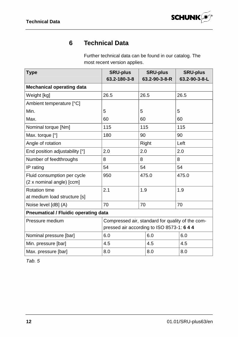
6 Technical Data
Further technical data can be found in our catalog. The
most recent version applies.
Type SRU-plus
63.2-180-3-8
SRU-plus
63.2-90-3-8-R
SRU-plus
63.2-90-3-8-L
Mechanical operating data
Weight [kg] 26.5 26.5 26.5
Ambient temperature [°C]
Min. 5 5 5
Max. 60 60 60
Nominal torque [Nm] 115 115 115
Max. torque [°] 180 90 90
Angle of rotation Right Left
End position adjustability [°] 2.0 2.0 2.0
Number of feedthroughs 8 8 8
IP rating 54 54 54
Fluid consumption per cycle
(2 x nominal angle) [ccm]
950 475.0 475.0
Rotation time
at medium load structure [s]
2.1 1.9 1.9
Noise level [dB] (A) 70 70 70
Pneumatical / Fluidic operating data
Pressure medium Compressed air, standard for quality of the com-
pressed air according to ISO 8573-1: 6 4 4
Nominal pressure [bar] 6.0 6.0 6.0
Min. pressure [bar] 4.5 4.5 4.5
Max. pressure [bar] 8.0 8.0 8.0
Tab. 5

Assembly and installation
01.01/SRU-plus63/en 13
7 Assembly and installation
7.1 Mechanical connection
WARNING
Risk of injury when the machine/system moves
unexpectedly
Switch off power supply.
The module can be mounted on the base side:
Fig. 1 Möglichkeiten der Montage von unten und oben
Attach to the two internal threads or screws M12 x 100 and
use for centering the pins from the enclosed pack (71).
Mounting

Assembly and installation
14 01.01/SRU-plus63/en
Fig. 2: Mounting options with an adapter plate
Use the 2- fitting screws (77) and the 2 cap screws (75)
from the pack.
Mount at the bottom end on the internal threads of the pi-
nion.
2 threaded holes 2 holes for fit-
ting srews

Assembly and installation
01.01/SRU-plus63/en 15
7.2 Air connection
WARNING
Damage to the rotary module possible! The rotary module can be damaged if it arrives too abruptly in the end position.
• The rotary motion must reach the end position without jerk or bounce.
• Therefore flow control valves and shock absorbers must be used.
• Please observe the information in the catalog pages.
WARNING
Risk of injury when the machine/system moves
unexpectedly
Switch off power supply.
CAUTION
If the max. permissible mass on each jaw set:
Module attach fittings on the throttle.
Note
• Observe the requirements for the air supply
(see Chapter°6, Page 11 and the module data sheet).
The air connections in all blocks are arranged in the front
side at the same position for the pivotal movement.
These connectors are equipped with flow control valves
from the pack.
Optionally the units could be connected directly tubeless
from the ground or out of a side surface.
Use genereally throttle check valves for the connection.
Open only the necessary air connections.

Assembly and installation
16 01.01/SRU-plus63/en
Seal unused air connections with the screw-cap from the
pack.
Use for the tubeless direct connection the two O-rings
(73) from the pack.
Fig. 3 Air connections
Assembly and installation
01.01/SRU-plus63/en 17
7.2.1 Rotary feedthrough
Fig. 4 Measurements for tubeless pinion side direct connection
Fig. 5 View from sprocket to stop (CCW), air connection left.
View X
(pinion side)

Adjustment of the shock absorber stroke
18 01.01/SRU-plus63/en
8 Adjustment of the shock absorber stroke
NOTE
When received from the factory, the unit is set to utilize the
maximum shock absorber stroke.
The shock absorber stroke is too long and the end position
is reached too slowly.
The shock absorber stroke is too short and the unit arrives
in the end position too abruptly.
Optimal shock absorber stroke.
Setting the speed
01.01/SRU-plus63/en 19
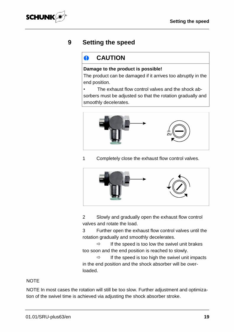
9 Setting the speed
CAUTION
Damage to the product is possible!
The product can be damaged if it arrives too abruptly in the
end position.
• The exhaust flow control valves and the shock ab-
sorbers must be adjusted so that the rotation gradually and
smoothly decelerates.
1 Completely close the exhaust flow control valves.
2 Slowly and gradually open the exhaust flow control
valves and rotate the load.
3 Further open the exhaust flow control valves until the
rotation gradually and smoothly decelerates.
If the speed is too low the swivel unit brakes
too soon and the end position is reached to slowly.
If the speed is too high the swivel unit impacts
in the end position and the shock absorber will be over-
loaded.
NOTE
NOTE In most cases the rotation will still be too slow. Further adjustment and optimiza-
tion of the swivel time is achieved via adjusting the shock absorber stroke.
Swivel angle adjustment
20 01.01/SRU-plus63/en
10 Swivel angle adjustment
10.1 Fine adjustment of end positions 0° und 180°
(See chapter 12 Assembly drawing for sectional view of the
position number)
1. Act upon connection A until the Rotary Actuator has
reached its final position.
2. Solve now the nut (53) for B and adjust the final position
of the adjusting sleeve (10).
3. Tighten the locknut (53) to counterattack and to review
the end position.
Proceed exactly in the same way for the second end stop.

Swivel angle adjustment
01.01/SRU-plus63/en 21
10.2 Sensors
The gripper is prepared for the designed use of the sensors
IN 80 and MMS 30.
If you require further information on sensor operation,
contact your SCHUNK contact person or download
information from our homepage.
Technical data of the sensors can be found in the data
sheets (included in the scope of delivery).
CAUTION
Damaging the sensor during installation is possible
Note, the max. torque for the screw is 0.2 Nm.
10.2.1 Inductive proximity switches IN 80
1 brown 2 black 3 blue
Fig. 6 Inductive proximity switch IN 80
Available types:
– IN 80-S-M8 (switching function: NOC)
– IN 80-S-M12 (switching function: NOC)

Swivel angle adjustment
22 01.01/SRU-plus63/en
The installed inductive proximity switch is polarity protected
and short circuit protected.
During proper usage of the proximity switch, note the follow-
ing:
• Do not pull on the cable of the sensor.
• Do not allow the sensor to dangle from the cable.
• Do not overtighten the mounting screw or the clamp
mounting.
• Comply the allowable bending radius of the cable (see
catalog).
• Avoid contact of the proximity switch with hard objects,
as well as chemicals, in particular nitric acid, chromic
acid and sulfuric acid.
The inductive proximity switches are electronic components,
which can react sensitively to high-frequency interference or
electromagnetic fields.
• Check to make sure that the cable is fastened and
installed correctly. Provide for sufficient clearance to
sources of high-frequency interference and their supply
cables.
• Parallel switching of several sensor outputs of the same
type (npn, pnp) is permissible, but does not increase the
permissible load current.
• Note that the leakage current of the individual sensors
(ca. 2 mA) is cumulative.

Swivel angle adjustment
01.01/SRU-plus63/en 23
Block A and B:
1. Set the quick clamping sleeve (92) so, that the pivoting
cam (94) has passed about 0.5 mm spacing.
2. Clamp then the sleeve with the threaded pin (93) easily.
3. Turn the set screw (94-3) about ½ at the switch cam
(94), so the cam can be moved.
4. The connection at A pressurize until the gripper head
has reached its final position.
5. Now slide the puck until the switch is applied at B.
6. Tighten the pinion and the set screw (94-3) again from
this position
The setting for the other end position is the same.
Installation and
adjustment of the
proximity switch

Swivel angle adjustment
24 01.01/SRU-plus63/en
10.2.2 Magnetic switch MMS 30
1 braun 2 schwarz 3 blau
Fig. 7
Note
With the use of adapter plates from ferromagnetic material
(eg. ordinary structural steel), the module must first be
mounted on the adapter plate, before the positions of the
magnetic switches. This is necessary because the use of
magnetizable material of the sensor changes the shifting
points.
RMS sensors have a greater hysteresis than the MMS sen-
sors. Thus it may be that short gripper strockes with the
RMS sensors are not retrievable..
1. Pressurize a connection of the rotary unit until it reached
one of their settings.
2. Push a button on one of the T-slots and position it so
that its make contact addresses and transmits the
sensor signal.
3. Fix the switch by tightening the set screw (SW 1.5)
4. Pressurize the unit through the second connection and
fix it in the other end position. The second proximity
switch procedure is analogous.
Installation and
adjustment of the
proximity switch
Maintenance and care
01.01/SRU-plus63/en 25
11 Maintenance and care
11.1 Maintenance and lubrication intervals
CAUTION
Environmental temperatures of more than 60 °C/ 140 °F
can harden the used lubricants faster!
Lubrication and maintenance works have to be carried
out more often.
Type 63
Interval [Mio. cycles] 1
Tab. 6
11.2 Lubricants/Lubrication points (ba-
sic lubrication)
We recommend the lubricants listed. Provably equivalent
lubricants can also be used.
During maintenance, treat all grease areas with
lubricant.
Lubrication points Lubricant
Serration and pinions Molykote BR 2 plus
meta sliding surfaces Renolit HLT 2
All seals
Tab. 7
11.3 Dismantling the module
CAUTION
Damage to the O-rings during installation is possible.
Caution when mounting the rotary feedthrough (3).
1. Remove all pressure lines
2. Unscrew the cover A (16) cover (11).

Maintenance and care
26 01.01/SRU-plus63/en
3. Mark during the installation the position of the pinion (2),
the piston (5) and for the version with integrated air the
passage of the rotary joint (3).
4. Dismantle the piston (5) at one point.
5. Remove the distributor flange (3) and the locking ring (52).
6. Press the pinion (2) of the housing.
7. Slide the rack (30) and the piston (5) out of the housing.
Remove all seals.
11.4 Servicing and assembling the module
(For item see chapter 12 Assembly drawing, page 28)
WARNING
Risk of injury due to spring forces.
Carefully disassemble the module.
Alle Teile gründlich reinigen und auf Beschädigung bzw.
Verschleiß prüfen.
Replace all wearing parts / seals.
– The wearing parts are listed in the spare part and
sealing kit list (see chapter 13, from page 29).
– The seals are in the sealing kit.
The ID number of the sealing kit is in the wearing part
and sealing kit list (see chapter 13, from page 29).
Treat all grease areas with lubricant (see chapter 11.2,
page 25).
Oil or grease bare outside steel parts.
Assembly takes place in the opposite order to disassembly.
Observe the following:
Unless otherwise specified, secure all screws and nuts
with Loctite® 243 and tighten with the appropriate
tightening torque.
Servicing
Assembly
Maintenance and care
01.01/SRU-plus63/en 27
11.5 Replacing and adjusting the shock absorber
Note
The shock absorbers are specially tested and can only be
sourced from SCHUNK. The shock absorbers have a re-
stricted lifetime, depending on the load.
Test the shock absorbers for function regularly.
The shock absorbers function correctly when the module
moves smoothly into the limit positions.
CAUTION
Rotary actuator SRU-plus 63 has no adjusting screw
for the shock absorber.
Adjust the shock absorber properly.
1. Fix the swivel with the hock wrench (79) and loosing the
sealing nut (54) of the shock absorber.
2. Turn the shock absorber (32) from the thread.
3. Fasten the new shock absorber until it stops.
4. Mount the O-ring (49) on the shock absorber.
5. Set the shock absorber by unscrewing the shock
absorber stroke.
6. Fix the swivel with the hock wrench (79) and tighten the
sealing nut (54) of the shock absorber.
7. Check the setting by repeatedly swiveling.
Replacement of
shock absorber
Assembly drawing
28 01.01/SRU-plus63/en
12 Assembly drawing
Fig. 8 section illustration
Fig. 9 Version A
37 2 3 44 52
76
71
4 75 77
60
38
33 16 92 36 30 5 93 11
49
32
54 10 53 48 42 51 40 1 94 95 91

Spare parts
01.01/SRU-plus63/en 29
13 Spare parts
(For item see chapter 12 Assembly drawing, page 28)
Pos. Ident.-Nr. amount description
1 5511023 1 Housing
2 5511024 1 Pinion
3 5511025 1 Distributor flange
4 5511026 1 Cam holder ring
5 5511027 4 Piston
10 5520650 2 Adjustment sleeve
11 5511033 1 Cover
16 5511036 1 Cover A
30 5511035 2 Rack
31 9659012 8 Locking screw R1/8“
32* 9955215 2 Shock absorber WP-M 1,5X2-166
33*** 9937258 2 Throttle check valve G1/4“
34 9937266 4 Guide sleeve SINTB 30/35x20
36 9936899 1 Ring magnet 3,1x10x5
37 9632008 1 Deep groove ball bearings 6011 2RS1 55x90x18
38 9937259 1 Deep groove ball bearings 6016 2RS1 80x125x22
40* 9612662 4 Cylinder gasket 63x53x4.2 Z8
40** 4 Cylinder gasket 63x53x4.2 Z8
42* 9935792 4 O-ring DIN 3771 NBR 71,5x1,5
42** 4 O-ring DIN 3771 NBR 71,5x1,5
44* 9611146 9 O-ring DIN 3771 NBR 44,17x1,78
44** 9 O-ring DIN 3771 NBR 44.17x1.78
45* 9611090 1 O-ring DIN 3771 NBR 126,72x1,78
45** 1 O-ring DIN 3771 NBR 126,72x1.78
46* 9611228 4 O-ring DIN 3771 NBR 7x1,5
46** 4 O-ring DIN 3771 NBR 7x1,5
47** 12 O-ring DIN 3771 NBR 6x1,5
48* 9611118 2 O-ring DIN 3771 NBR 50x1,5
48** 2 O-ring DIN 3771 NBR 50 x1,5
49* 9611043 2 O-ring DIN 3771 NBR 36,09x3,53
Spare parts
30 01.01/SRU-plus63/en
Pos. Ident.-Nr. amount description
49** 2 O-ring DIN 3771 NBR 36,09x3,53
51* 9937260 2 Safety ring DIN 471 A 50x2
52 9620013 1 Safety ring DIN 471 A 55x2
53 9937261 2 Locknut DIN 1804 M55x1,5
54 9955888 2 Locknut DIN 1804 M45x1,5
55 99420210 26 Setscrew DIN EN ISO 4026/A2
56 9670521 14 Setscrew DIN EN ISO 4026/A2
57 9937262 1 Spacer 6x12
58 9650023 1 Fitting disc DIN 988
59 9650427 1 Fitting disc DIN 988
60 9664501 2 Countersunk screw DIN EN ISO 10642/A2 M3x8
61 9936469 1 Screw DIN EN ISO 4762/A2 M2.5x20
62 9660432 2 Screw DIN EN ISO 4762/A2 M8x20
63 9935460 6 Screw DIN EN ISO 4762/A2 M10x20
64 9661012 4 Screw DIN 7984/8.8 M6x12
65 9660450 6 Screw DIN EN ISO 4762/A2 M10x30
70*** 9939382 2 Centering sleeve
71*** 9939383 2 Centering sleeve
73*** 9611081 16 O-ring DIN 3771 NBR 6x1,5
73** 16 O-ring DIN 3771 NBR 6x1.5
74*** 9611055 2 O-ring DIN 3771 NBR 8x2
74** 2 O-ring DIN 3771 NBR 8x2
75*** 9937263 2 Screw DIN EN ISO 4762/A2 M10x25
77*** 9937265 2 Fitting screw 12.9 12 M10x20
78*** 9659004 2 Locking screw DIN 908 R1/4“
79*** 9201051 2 Hook wrench 68-75
99 5511 038 1 Accessories pack
A 0370702 1 Seal kit
Tab. 8
* Replace spare parts for maintenance: not included in gasket set (A)
** Replace spare parts for maintenance: Order gasket set (A).
*** Contain in the accessories pack (99).
Translation of original declaration of incorporation
01.01/SRU-plus63/en 31
14 Translation of original declaration of
incorporation
in terms of the Directive 2006/42/EG, Annex II, Part 1.B of the European Parliament and of the Council on machinery.
Manufacturer/
distributor
SCHUNK GmbH & Co. KG.
Spann- und Greiftechnik
Bahnhofstr. 106 – 134
74348 Lauffen/Neckar, Germany
We hereby declare that on the date of the declaration the following incomplete machine com-
plied with all basic safety and health regulations found in the directive 2006/42/EC of the
European Parliament and of the Council on machinery. The declaration is rendered invalid if
modifications are made to the product.
Product designation: Pneumatic Swivel Unit / SRU-plus 63
ID number: 0354801; 0354841; 0354851
The incomplete machine may not be put into operation until conformity of the machine into
which the incomplete machine is to be installed with the provisions of the Machinery Directive
(2006/42/EC) is confirmed.
Applied harmonized standards, especially:
DIN EN ISO
12100:2011-03
Safety of machinery - General principles for design - Risk assessment
and risk reduction
The manufacturer agrees to forward on demand the relevant technical documentation for the
partly completed machinery in electronic form to state offices.
The special technical documents according to Appendix VII, Part B belonging to the in-
complete machine have been compiled.
Person authorized to compile the technical documentation:
Robert Leuthner, Address: see manufacturer's address
Lauffen/Neckar, June 2016
p.p. Ralf Winkler,
Head of Gripping Systems Development

Translation of original declaration of incorporation
32 01.01/SRU-plus63/en