PNEUMATIC PIPE RAMMER - TT Technologies & Compressed Air Spoil Removal Procedures . . . . . . . . ....
64
® GRUNDORAM Operators & Parts Manual TT TECHNOLOGIES, Inc. PNEUMATIC PIPE RAMMER
-
Upload
phungthien -
Category
Documents
-
view
221 -
download
3
Transcript of PNEUMATIC PIPE RAMMER - TT Technologies & Compressed Air Spoil Removal Procedures . . . . . . . . ....

®
GRUNDORAMOperators & Parts Manual
TT TECHNOLOGIES, Inc.
PNEUMATIC PIPE RAMMER
2 TT TECHNOLOGIES, INC.
Table of Contents
Safety SectionSafety Information about the GRUNDORAM . . . . . . . . .4-6
OperationsGeneral Information . . . . . . . . . . . . . . . . . . . . . . . . . . . . . . . . . . . .6
General Description . . . . . . . . . . . . . . . . . . . . . . . . . . . . . . . . . . . . .6
Basic Operation & Applications . . . . . . . . . . . . . . . . . . . . . . . . . . . . .6
MINI-GRUNDORAM . . . . . . . . . . . . . . . . . . . . . . . . . . . . . . . . . . . . .8
Technical Specifications . . . . . . . . . . . . . . . . . . . . . . . . . . . . . . .9
Compressor System Requirements . . . . . . . . . . . . . . . . . . . . . . . . . .9
Operational Capacities . . . . . . . . . . . . . . . . . . . . . . . . . . . . . . . . . . .9
Physical Specs . . . . . . . . . . . . . . . . . . . . . . . . . . . . . . . . . . . . . . . .10
Safe Operating Procedures . . . . . . . . . . . . . . . . . . . . . . . . . . . .11
Work Area Safety . . . . . . . . . . . . . . . . . . . . . . . . . . . . . . . . . . . . . .11
Pneumatic Equipment . . . . . . . . . . . . . . . . . . . . . . . . . . . . . . . . . .11
Job Site Considerations . . . . . . . . . . . . . . . . . . . . . . . . . . . . . . . . . .11
Set Up . . . . . . . . . . . . . . . . . . . . . . . . . . . . . . . . . . . . . . . . . . . . . . . . . .11
General Information & Basic Set Up . . . . . . . . . . . . . . . . . . . . . . . .11
Compressor Connections . . . . . . . . . . . . . . . . . . . . . . . . . . . . . . . .12
Lubricator . . . . . . . . . . . . . . . . . . . . . . . . . . . . . . . . . . . . . . . . . . . .12
Pit Description/Construction . . . . . . . . . . . . . . . . . . . . . . . . . . . . . . .12
Cradle/Adjustable Bearing Stand . . . . . . . . . . . . . . . . . . . . . . . . . . .12
Support System Track/I-Beam . . . . . . . . . . . . . . . . . . . . . . . . . . . . .14
Tapered Locking Ram Cones . . . . . . . . . . . . . . . . . . . . . . . . . . . . .15
Cotter Segments . . . . . . . . . . . . . . . . . . . . . . . . . . . . . . . . . . . . . . .16
Soil Port . . . . . . . . . . . . . . . . . . . . . . . . . . . . . . . . . . . . . . . . . . . . .17
Pressure Plate . . . . . . . . . . . . . . . . . . . . . . . . . . . . . . . . . . . . . . . .17
Cutting Shoes . . . . . . . . . . . . . . . . . . . . . . . . . . . . . . . . . . . . . . . . .18
Tensioning Straps . . . . . . . . . . . . . . . . . . . . . . . . . . . . . . . . . . . . . .19
Bentonite/Lubrication . . . . . . . . . . . . . . . . . . . . . . . . . . . . . . . . . . . .19
3.
4.
1.
2.
5.

3TT TECHNOLOGIES, INC.
Operation Instructions . . . . . . . . . . . . . . . . . . . . . . . . . . . . . . . .20
General Information . . . . . . . . . . . . . . . . . . . . . . . . . . . . . . . . . . . . .20
Set Up & Assembly . . . . . . . . . . . . . . . . . . . . . . . . . . . . . . . . . . . . .20
Testing the Rammer . . . . . . . . . . . . . . . . . . . . . . . . . . . . . . . . . . . .20
Ram First Foot of Pipe . . . . . . . . . . . . . . . . . . . . . . . . . . . . . . . . . .20
Ram Second Foot of Pipe . . . . . . . . . . . . . . . . . . . . . . . . . . . . . . . .20
Continue Ramming . . . . . . . . . . . . . . . . . . . . . . . . . . . . . . . . . . . . .21
Install Second Pipe Section . . . . . . . . . . . . . . . . . . . . . . . . . . . . . . .21
Breakdown/Tool Removal . . . . . . . . . . . . . . . . . . . . . . . . . . . . .21
Remove Tension Straps or Chains . . . . . . . . . . . . . . . . . . . . . . . . . .21
Remove GRUNDORAM Tool & Accessories from Pipe Section . . . .21
Spoil Removal . . . . . . . . . . . . . . . . . . . . . . . . . . . . . . . . . . . . . . . . . .22
Compressed Air Spoil Removal Procedures . . . . . . . . . . . . . . . . . . .22
Water & Compressed Air Spoil Removal Procedures . . . . . . . . . . . .23
Maintenance . . . . . . . . . . . . . . . . . . . . . . . . . . . . . . . . . . . . . . . . . . .25
GRUNDORAM Tool . . . . . . . . . . . . . . . . . . . . . . . . . . . . . . . . . . . . .25
Mini-Atlas GRUNDORAM Tool . . . . . . . . . . . . . . . . . . . . . . . . . . . . .32
PCG GRUNDORAM Tool . . . . . . . . . . . . . . . . . . . . . . . . . . . . . . . .38
Troubleshooting Guide . . . . . . . . . . . . . . . . . . . . . . . . . . . . . . . .50
Warranty Information . . . . . . . . . . . . . . . . . . . . . . . . . . . . . . . . . .51
Appendix . . . . . . . . . . . . . . . . . . . . . . . . . . . . . . . . . . . . . . . . . . . . . . .52
095 David Parts List . . . . . . . . . . . . . . . . . . . . . . . . . . . . . . . . . . . .52
130 Atlas Parts List . . . . . . . . . . . . . . . . . . . . . . . . . . . . . . . . . . . . .53
130 Mini-Atlas Parts List . . . . . . . . . . . . . . . . . . . . . . . . . . . . . . . . .54
145 Titan Parts List . . . . . . . . . . . . . . . . . . . . . . . . . . . . . . . . . . . . .55
180 Olympus Parts List . . . . . . . . . . . . . . . . . . . . . . . . . . . . . . . . . .56
180 Mini-Olympus Parts List . . . . . . . . . . . . . . . . . . . . . . . . . . . . . .57
220 Hercules Parts List . . . . . . . . . . . . . . . . . . . . . . . . . . . . . . . . . .58
260 Gigant Parts List . . . . . . . . . . . . . . . . . . . . . . . . . . . . . . . . . . . .59
260 Mini-Gigant Parts List . . . . . . . . . . . . . . . . . . . . . . . . . . . . . . . .60
350 Koloss Parts List . . . . . . . . . . . . . . . . . . . . . . . . . . . . . . . . . . .61
450 Goliath Parts List . . . . . . . . . . . . . . . . . . . . . . . . . . . . . . . . . . .62
600 Taurus Parts List . . . . . . . . . . . . . . . . . . . . . . . . . . . . . . . . . . .63
6.
7.
8.
9.
10.
11.
12.

4 TT TECHNOLOGIES, INC.
SAVE THESE INSTRUCTIONS
1.Important Safety InstructionsThis symbol calls attention to important safety instructions which, if notfollowed, could result in serious personal injury or death.
Read, understand and observe all safety information and instructions inthis manual, and on safety decals on the GRUNDORAM before usingit. For safety reasons, read the operators manual carefully andexercise caution while using the GRUNDORAM. Please notespecific safety requirements as explained by procedures calledout in this manual. Failure to follow these instructions could result in serious personalinjury or death.
All tools, materials and equipment manufactured and supplied by TT Technologies, Inc.are designed to be used by qualified and trained personnel only. TT Technologies, Inc.will not be held liable for any injury or damage to either people or property resulting fromthe misuse of TT Technologies equipment.
Please save this user's guide for future reference and have it available to alloperating personnel. Personnel should thoroughly read this operating manual.
DANGER:
WARNING:
Contact with electrical lines may result indeath or injury. The user should be properlytrained in correct procedures for work aroundelectrical lines.
Before you dig, contact the local utilities todetermine the location of all area service lines.
WEAR SAFETYGLASSES
WEAR SAFETYSHOES
WEAR SAFETYGLOVES
WEAR HARD HAT
READ MANUALFIRST
CAUTION: When working with compressed air, follownecessary precautions to avoid injury.

5TT TECHNOLOGIES, INC.
SAVE THESE INSTRUCTIONS
Follow all safety instructions concerning safety and possible danger.
Do not modify or remove the safety devices or warning labels of this machine. Keep alllabels regarding safety and possible danger on the machine in good, readable condition.Special care is required before and during the safety check.
Every crewmember should fully understand the safety measures required for theoperation and should be capable of following these regulations individually.
The GRUNDORAM is manufactured to the current technical safety-relevant regulations.Nevertheless, the use of the machine may represent a danger to the health and life ofusers or third parties. Always ensure that you pay particular attention to warnings,safety labels and instructions.
Read Operators ManualBefore starting the machine, fulfill all safety related requirements. Allpersonnel should thoroughly read this operating manual.
Follow all safety instructions concerning safety and possible danger.Do not modify or remove the safety devices or warning labels of thismachine. Keep all labels regarding safety and possible danger on themachine in good, readable condition. Special care is required before andduring the safety check.
Every crew member should fully understand the safety measures required forthe operation and should be capable of following these regulations individually.
Call Before You DigCheck the existence and exact position of buried pipe and cables bycontacting the respective utilities or owners of networks. The exact anddefinite existence and position of buried cables and pipes should be definedby trial pits or using cable and pipe detection equipment or other means.
Cable StrikeShould you accidentally hit an electrical cable, immediately leave the site,ensure no one enters and contact the electrical company to turn off the supply.In case of a cable strike, the danger resulting from that damaged electric cablecan only be evaluated following detailed information by the respectiveelectrical company. Never rely on your own knowledge as to types of cables,safety measures and protective measures that may not be correct for thetype of cable encountered. Always consider cables to be “live” and apotential danger to life. Do not re-enter the site until authorized by theelectrical company.
Disconnecting Air Hoses!Only disconnect pressure free hoses. Always turn off the compressor andbleed all air before disconnecting hoses. Before starting any maintenance orinspection work, ensure that the GRUNDORAM is not connected to any airsupply. During repair and maintenance operations always follow therespective safety recommendations. Repair and maintenance operations arerestricted to trained and certified staff only.
Do Not Over-Pressurize!Do not over pressurize, otherwise explosion or serious damage may occur.Do not exceed the operating pressure of 7 bar (100 psi). Make sure to onlyuse original T.T. hoses with T.T. couplings that are suitable for this pressure.

6 TT TECHNOLOGIES, INC.
No Loose ClothesDo not wear loose clothes or long hair. Danger of body injury by loose clothesor hair being caught in the moving parts of the machine.
Safety EquipmentThe operating crew should always wear the appropriate safety equipment, i.e.,safety shoes/boots, hard hat, safety glasses, gloves, ear protection etc.
Operation by Qualified Personnel OnlyOperation of the GRUNDORAM should be carried out by suitably trained,qualified, and certified personnel only. New operators or operators in trainingshould be working under the constant supervision of a qualified person.Personnel operating the GRUNDORAM should have sufficiently studied theoperating manual.
Skin Burning Warning This item can be hot or cold. Do not touch as burns may result.
GRUNDORAM MaintenanceUse the machine only if it is in perfect working order and after studying theoperating manual, particularly the safety-related sections. Always check themachine and its accessories for unwanted movements.
To guarantee long life, regular maintenance is essential. Inadequate orinfrequent repair and maintenance operations may lead to accidents,downtime and costly repairs of the machine.
During repair and maintenance operations always follow the respective safetyrecommendations. Repair and maintenance operations are restricted totrained and certified staff only.
Transporting the GRUNDORAMDanger of accidents. Do not overload the transportation vehicle.
Starting & Exit Pit ExcavationMake sure that start and exit pits are excavated and shored as necessary tocomply with OSHA regulations and guard against collapse.
General InformationA. General DescriptionFor more than 35 years, TT Technologies has been a leader in trenchless replacementsystems. Today, with more than 200 patents worldwide, TT Technologies’ tools are usedin trenchless applications ranging from pipe pulling, pipe bursting, slip-lining, directionaldrilling, and pipe ramming.
As with all construction operations, safe operational procedures must be observed. Thesafety alert symbol is used in this manual to advise you of the potential to bodily injuryor death.
B. Basic Operation & ApplicationsThe GRUNDORAM pneumatic ramming tool is used for the trenchless installation ofsteel pipe through a wide variety of soil types, without any rise or fall in the ground’ssurface. Models are available that will push pipe with anywhere from 80 to over 1,000tons of thrust.
2.

7TT TECHNOLOGIES, INC.
Although the GRUNDORAM is usually used for horizontal pipe ramming beneathroads and railroad lines (see Fig. 1), it can also be used for vertical pipe & pile driving(see Fig. 2). In addition, the GRUNDORAM can be used to drive steel pipe at an anglethrough rocky soils for directional drilling operations, a technique known asconductor barrel technology (see Fig. 3).
Without the use of any external supportor fixed abutment, the GRUNDORAMliterally drives the steel pipe into theground, using a dynamic hammeraction. Standard pipe rammingaccessories can accommodate pipediameters up to 80 inches (2032 mm)and installation distances up to 265 feet(80.8 m). Contact TT Technologies forspecific information regarding piperamming equipment. It is important tochoose the correct GRUNDORAMmodel for the job, based upon pipediameter and the length of installation(see Fig. 4).
GRUNDORAM pipe rammers can also be used to free stuck HDD drill stems andproduct pipe including steel and HDPE (see Figs. 5 & 6). For more information onGRUNDORAM directional assist applications, contact TT Technologies customer serviceat 1-800-533-2078.
FIG. 1: HORIZONTAL PIPE RAM FIG. 2: VERTICAL PILE & PIPE RAM
Pipe Rammerinstalls steel casingsfor clean bore start
Percussive Force
FIG. 3: CONDUCTOR BARREL
Tool Tool Diameter Length Weight Strokes/ Air Cons. Recomm. Pipe Dia. Bore Length
Model in. (mm) in. (mm) lbs. (kg) Minute cfm (m3/min) In. (mm) ft. (m)
Mini-Atlas 5 (125) 37 (946) 132 (60) 580 60 (1.7) 2–8 (50–200) 50 (15)
Titan 5.7 (145) 61 (1545) 302 (137) 310 141 (4.0) 8–15 (200–400) 80 (25)
Mini-Olympus 7 (180) 43 (1080) 385 (175) 500 124 (3.5) 4–16 (100–400) 80 (25)
Olympus 7 (180) 66 (1690) 507 (230) 280 177 (4.5) 8–20 (200–500) 115 (35)
PCG 180 7 (180) 66 (1690) 490 (222) 280 159 (4.5) 8–20 (200–500) 115 (35)
Hercules 8.5 (216) 75 (1913) 811 (368) 340 282 (6.5) 12–20 (300–500) 130 (40)
HV 220 8.5 (216) 79 (2010) 945 (429) 300 282 (6.5) 12–20 (300–500) 130 (40)
Mini-Gigant 10.5 (270) 48 (1230) 1014 (460) 430 353 (10.0) 8–24 (200–600) 115 (35)
Gigant 10.5 (270) 79 (2010) 1356 (615) 310 424 (12.0) 15–32 (400–800) 165 (50)
PCG 270 10.5 (270) 84 (2134) 1540 (699) 310 424 (12.0) 15–32 (400–800) 165 (50)
Koloss 14 (350) 92 (2341) 2601 (1180) 220 706 (20.0) 20–48 (500–1200) 230 (70)
KV 350 14 (350) 102 (2591) 3375 (1531) 220 706 (20.0) 20–48 (500–1200) 230 (70)
Goliath 18 (460) 112 (2852) 5434 (2465) 180 1236 (35.0) 24–56 (600–1400) 265 (80)
Taurus 24 (600) 144 (3645) 10,580 (4800) 180 1766 (50.0) 56–78 (1400–2000) 265 (80)
Maximum bore lengths will vary depending on actual pipe diameter installed and GRUNDORAM tool used to install it. Contact TT Technologies for detailed pipe vs bore length information.
GRUNDORAM TOOL SPECIFICATIONS
FIG. 4: GRUNDORAM TOOL SIZE DEPENDS ON PIPE DIAMETER & LENGTH
8 TT TECHNOLOGIES, INC.
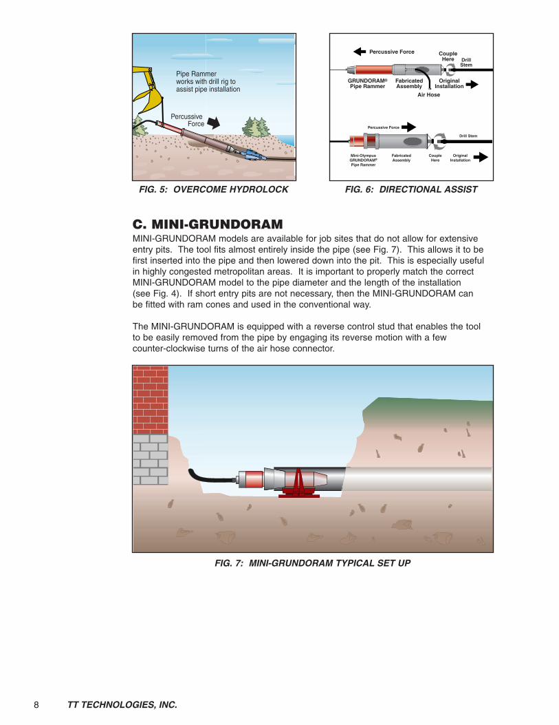
C. MINI-GRUNDORAMMINI-GRUNDORAM models are available for job sites that do not allow for extensiveentry pits. The tool fits almost entirely inside the pipe (see Fig. 7). This allows it to befirst inserted into the pipe and then lowered down into the pit. This is especially usefulin highly congested metropolitan areas. It is important to properly match the correctMINI-GRUNDORAM model to the pipe diameter and the length of the installation(see Fig. 4). If short entry pits are not necessary, then the MINI-GRUNDORAM canbe fitted with ram cones and used in the conventional way.
The MINI-GRUNDORAM is equipped with a reverse control stud that enables the toolto be easily removed from the pipe by engaging its reverse motion with a fewcounter-clockwise turns of the air hose connector.
Pipe Rammerworks with drill rig toassist pipe installation
Percussive Force
GRUNDORAM®
Pipe RammerFabricatedAssembly
Percussive ForceDrillStem
CoupleHere
Air Hose
OriginalInstallation
FIG. 5: OVERCOME HYDROLOCK FIG. 6: DIRECTIONAL ASSIST
FIG. 7: MINI-GRUNDORAM TYPICAL SET UP
Mini-OlympusGRUNDORAM®
Pipe Rammer
FabricatedAssembly
Percussive Force
Drill Stem
CoupleHere
OriginalInstallation

9
Technical SpecificationsA. Compressor System RequirementsAll tools require a compressor outlet pressure of 85-100 psi. TT Technologies suppliesair hoses that are sized to operate each GRUNDORAM model at its highest efficiency.Do not use smaller diameter hoses.
If two compressors are used in parallel, place non-return valves between their outlets toensure that air is not being pushed from one compressor back into the other. Install thenon-return valves directly to the T-connector that joins the two lines together, and makesure that the non-return valves are facing in the proper direction (see Fig. 8).
WARNING: Incorrect hoses may fail.Only use air hoses that are rated forat least 145 psi. Install safety whipchecks on all air hose connections.Failure to do so could result inserious personal injury or death.
B. OperationalCapacitiesMinimum Wall Thickness (see Fig 9),Tool Selection chart (see Fig. 4), BoreLength Recommendations chart(see Fig. 10) and an Entry PitCalculation chart (see Fig. 11).
3.
Air Compressors
Lubricator Ball Valve
Non-ReturnValves
50'Air Hose
7' Connection Hose
7' Connection Hoses
GRUNDORAM®
Tool
Distributor
RolledHoses
Whip Check
FIG. 8: GRUNDORAM SET UP WITH COMPRESSORS (MINI-ATLAS—KOLOSS)
TT TECHNOLOGIES, INC.
Bores up to 65 ft(20 m)
Bores over 65 ft(20 m)
in. (mm) in. (mm) in. (mm)
6 (150) .25 (6.3) .27 (7.1)
8 (200) .25 (6.3) .27 (7.1)
10 (250) .25 (6.3) .27 (7.1)
12 (300) .25 (6.3) .27 (7.1)
14 (350) .27 (7.1) .31 (8.0)
16 (400) .27 (7.1) .31 (8.0)
18 (450) .31 (8.0) .39 (10.0)
20 (500) .31 (8.0) .39 (10.0)
24 (600) .39 (10.0) .47 (12.0)
28 (700) .39 (10.0) .47 (12.0)
30 (750) .47 (12.0) .55 (14.0)
32 (800) .47 (12.0) .55 (14.0)
36 (900) .47 (12.0) .62 (16.0)
40 (1000) .47 (12.0) .62 (16.0)
42 (1050) .59 (15.0) .62 (16.0)
48 (1200) .59 (15.0) .70 (18.0)
51 (1300) .62 (16.0) .70 (18.0)
55 (1400) .70 (18.0) .78 (20.0)
60 (1500) .75 (19.0) .87 (22.0)
72 (1800) .87 (22.0) 1.00 (25.0)
80 (2000) .875 (22.2) 1.00 (25.0)
Minimum Wall ThicknessPipeDiameter
WALL THICKNESSRECOMMENDATIONS
FIG. 9: MINIMUM WALL THICKNESS FIG. 10: BORE LENGTH EXAMPLE
As a rule of thumb therecommended bore length with
pipe diameters up to 32" (800 mm):
Pipe Diameter in mm divided by10 gives the bore length in m.
Example:Pipe Diameter of 200 mm divided
by 10 = up to max 20 m long.
The ratio should be used topreserve target accuracy.

10 TT TECHNOLOGIES, INC.
Generally, the bore pit needs to have a minimum length equal to the sum of themeasurements of the ramming tool, the ram cone, soil removal cone, the length of theproduct pipe sections being used, plus 5 feet of working space behind the tool.
C. Physical Specs (see Fig. 12).
Tool Tool Diameter Length Weight Strokes/ Air Cons. Recomm. Pipe Dia. Bore Length
Model in. (mm) in. (mm) lbs. (kg) Minute cfm (m3/min) In. (mm) ft. (m)
Mini-Atlas 5 (125) 37 (946) 132 (60) 580 60 (1.7) 2–8 (50–200) 50 (15)
Titan 5.7 (145) 61 (1545) 302 (137) 310 141 (4.0) 8–15 (200–400) 80 (25)
Mini-Olympus 7 (180) 43 (1080) 385 (175) 500 124 (3.5) 4–16 (100–400) 80 (25)
Olympus 7 (180) 66 (1690) 507 (230) 280 177 (4.5) 8–20 (200–500) 115 (35)
PCG 180 7 (180) 66 (1690) 490 (222) 280 159 (4.5) 8–20 (200–500) 115 (35)
Hercules 8.5 (216) 75 (1913) 811 (368) 340 282 (6.5) 12–20 (300–500) 130 (40)
HV 220 8.5 (216) 79 (2010) 945 (429) 300 282 (6.5) 12–20 (300–500) 130 (40)
Mini-Gigant 10.5 (270) 48 (1230) 1014 (460) 430 353 (10.0) 8–24 (200–600) 115 (35)
Gigant 10.5 (270) 79 (2010) 1356 (615) 310 424 (12.0) 15–32 (400–800) 165 (50)
PCG 270 10.5 (270) 84 (2134) 1540 (699) 310 424 (12.0) 15–32 (400–800) 165 (50)
Koloss 14 (350) 92 (2341) 2601 (1180) 220 706 (20.0) 20–48 (500–1200) 230 (70)
KV 350 14 (350) 102 (2591) 3375 (1531) 220 706 (20.0) 20–48 (500–1200) 230 (70)
Goliath 18 (460) 112 (2852) 5434 (2465) 180 1236 (35.0) 24–56 (600–1400) 265 (80)
Taurus 24 (600) 144 (3645) 10,580 (4800) 180 1766 (50.0) 56–78 (1400–2000) 265 (80)
Maximum bore lengths will vary depending on actual pipe diameter installed and GRUNDORAM tool used to install it. Contact TT Technologies for detailed pipe vs bore length information.
GRUNDORAM TOOL SPECIFICATIONS
FIG. 12: GRUNDORAM TECHNICAL SPECIFICATIONS
Example:Hercules GRUNDORAM tool dia. 8.5" (216 mm), steel pipe dia. 20" x .393"
(508 mm x 10 mm) with soil removal cone REK 43 000 501.
Components: Length in.(mm)GRUNDORAM Tool (L3) 86" (2190 mm)Tapered Locking Ram Cone (L2) 3.75" (95 mm)Segmented Ram Cones if used / etc.Soil Removal Cone (REK 43 000 501) (L1) 24.6" (600 mm)Pipe Length 238" (6000 mm)Additional Working Space 60" (1524 mm)
Pit Length (Total Minimum) 413" (10,490 mm)
FIG. 11: ENTRY PIT CALCULATION

11TT TECHNOLOGIES, INC.
Safe Operating PracticesA. Work Area Safety
1. Operator training is mandatory prior to use.2. Always follow manufacturer’s operating instructions.3. All safety devices must be in place before and during operation.4. Report any defects or safety device faults immediately.5. Stop operation immediately if any safety device fails.6. Maintenance work or inspections should be performed when the tool is off and
not connected to the air compressor.7. All safety devices must be replaced after maintenance or repair.8. Follow all normal construction safety procedures.
B. Pneumatic Equipment1. Tighten all connections before applying pressure. Relieve pressure when
servicing unit.2. Visually inspect all hoses and connections regularly. Service if needed.3. Do not exceed working pressure of pneumatic hoses. 4. Forced air creates flying debris. Always wear personal protective equipment.
Severe personal injury could result.
C. Job Site Considerations1. As with all construction operations, safe operational procedures must be
observed. The safety alert symbol is used in this manual to advise you of thepotential for bodily injury or death.
2. Prior to starting, check with the utility companies for the location and depth ofexisting cables and line.
3. Minimal ground cover is required with the GRUNDORAM resulting in shallowerand less expensive entrance and exit pits.
4. There is no need for fixed abutments when using the GRUNDORAM.
Set UpA. General Information & Basic Set UpGRUNDORAM pipe rammer uses pneumatic power to insert casings through a varietyof soils without a rise or slump to the ground surface. The soil is swallowed up insidethe casing and is then removed by using the air compressor to clean out the spoils(see Fig. 13). The GRUNDORAM pipe rammer does not require the use of backabutments, thus set up times are decreased.
5.
FIG. 13: TYPICAL GRUNDORAM SET UP
4.

12 TT TECHNOLOGIES, INC.
B. Compressor ConnectionsMake sure all hose connections are tight before starting the air compressor. Whendisconnecting the air hose make sure that all pressure is released first.
C. LubricatorProper lubrication is essential to the optimum performance of the GRUNDORAM.GRUNDO-OIL is fed into the GRUNDORAM through a lubricator (see Fig. 14). Thelubricator is connected between the compressor and the GRUNDORAM tool. Itatomizes the oil and feeds it into the GRUNDORAM through via compressed air. Oilflow can be regulated by adjusting the lubricator settings (see Fig. 15).
WARNING: System under pressure. Never unscrew the oil inlet under pressure.
GRUNDO-OIL is completely safe and biodegradable and has no harmful affects onrubber air hoses.
NOTE: In order to ensure adequate lubrication, tool lubricator must remain upright during while in use. Lubricator flow should be set at 0 when transporting.
NOTE: Increase lubricator’s normal setting by 1 during cold weather conditions.
D. Pit Description/ConstructionPipe ramming bore pits do not typically require the use of reinforced back abutmentsand are not restricted in the length or diameter of the product pipe sections that can beused. Bore pit preparations will, in part, be dictated by job site conditions and will varyby project.
Generally, the bore pit needs to have a minimum length equal to the sum of themeasurements of the ramming tool, the ram cone, soil removal cone, the length of theproduct pipe sections being used, plus 5 feet of working space behind the tool(see Fig. 11).
DANGER: Entrance & Exit Pits that are at least 3.93 feet (1.2 m) deep need tobe shored as necessary to comply with OSHA regulations and guard againstcollapse. Failure to do so could result in serious personal injury or death.
E. Cradle/Adjustable Bearing StandThe adjustable bearing stand is a heavy-duty mechanism that provides both support andalignment for the GRUNDORAM and the pipe. An inflatable air bladder allows for easyvertical adjustment (see Fig. 16). It can lift over three tons and can also be fitted with aspecial height adapter (see Fig. 17). With the use of ratcheting web straps, the bearingstand can be pulled along with the GRUNDORAM while it is pushing the pipe (see Fig. 18).
1 gal(3.78 l)
2 gal(7.5 l)
Mini-Atlas 2 - .15 (.5-.6)
Titan 2 - .20 (.7-.8)
Mini-Olympus 1-2 5 .20 (.7-.8)
Olympus 1-2 5 .20 (.7-.8)
Hercules - 4 .25 (1.0)
Mini-Gigant - 2-3 .30 (1.2)
Gigant - 2-3 .30 (1.2)
Koloss - 2 .40 (1.5)
Goliath - 2 .50 (2.0)
Taurus - 2 .80 (3.0)
Switch Position
LUBRICATOR SETTINGS
Tool ModelConsumptiongals/hr (l/h)
FIG. 14: LUBRICATOR FIG. 15: LUBRICATOR SETTINGS
f
h
g
e
a
c
d
a Transport handle
b Compressed air connection
c Compressed air connection
d Main frame
e Adjustment screw
f Oil level indicator
g Filling cap

13TT TECHNOLOGIES, INC.
FIG. 18: ADJUSTABLE BEARINGSTAND SET UP
G 450 0500 Type 1 up to Gigant 21x26x20(530x660x505)
170 (77) 6741 (30 kN)
G 450 0400 Type 2 for Koloss-Goliath 30x33x17(770x840x430)
267 (121) 6741 (30 kN)
TF 600 0400 Type 3 for Goliath-Taurus 30x36x17(770x920x430)
298 (135) 6741 (30 kN)
G4500450 Height Adapter for Type 2 30x24x7(770x610x170)
179 (81) N/A
TF 600 0450 Height Adapter for Type 3 30x31x9(770x790x225)
229 (104) N/A
ADJUSTABLE BEARING STAND SPECIFICATIONS
PartNumber Bearing Stand
Lifting Powerlbs. (kN)
WWeeiigghhttllbbss ((kkgg))
Size (LxWxH)in. (mm)
FIG. 16: ADJUSTABLE BEARING STAND
FIG. 17: ADJUSTABLE BEARING STAND SPECIFICATIONS
Cradle
Height adapter
1 Height adapter2 Fastening bolts
Base for rammer
Air cushion with air connectionand operating unit
Height adapter (bolted with main plate).
Operating unit
Carrier handles
Height adjustment

14 TT TECHNOLOGIES, INC.
F. Support System Track/I-BeamThe accuracy of the installation is dependent upon the first pipes alignment. For thisreason, it is imperative that the pipe has a stable support, in order to remain preciselyaligned throughout the ramming process; this is especially important for longinstallations.
Support tracks can be built using an I-beam (girder) (see Fig. 19), a C-channel(see Fig. 20), or a sheet pile (see Fig. 21), for larger pipe sizes you can use (2) I-beams(see Fig. 22). About 3 feet (1 m) should be left between the support track and the faceof the pit, in order to maintain an area for welding the pipe lengths together. Augertracks can also be used as support tracks for pipe ramming operations. Rammingsmaller diameter pipes can often be accomplished without any type of support track.Contact TT Technologies for specific information regarding pipe ramming support andtrack systems.
The support track should be secured in concrete, although in special cases, sand or gravel can be used. Recommended steel profiles (support tracks) in relation to variouspipe sizes (see Fig. 23).
4 (108) 1 x I 80 1 x C 80
6 (159) 1 x I 80 1 x C 80
8 (219) 1 x I 80 1 x C 80
10 (273) 1 x I 80 1 x C 80
12 (323) 1 x I 120 1 x C 120 KD III
16 (406) 1 x I 140 1 x C 140 KD III
20 (508) 1 x I 160 1 x C 160 KD III
24 (609) 1 x I 180 1 x C 180
32 (813) 1 x IPE 200 1 x C 220 KD IV
40 (1016) 2 x IPE 140 HKD 700/6
48 (1220) 2 x IPE 180
55 (1420) 2 x IPE 200
C-ChannelProfile
Pipe Outer Diameterin. (mm)
II -- BBeeaammPP rr oo ff ii ll ee
RREECCOOMMMMEENNDDAATTIIOONNSS OOFF SSTTEEEELL PPRROOFFIILLEESS FFOORR AALLIIGGNNIINNGG SSTTEEEELL PPIIPPEE
Sheet Pile
FIG. 23: RECOMMENDATIONS FOR ALIGNING PIPES
FIG. 19: ALIGNMENT ON I-BEAM FIG. 20: ALIGNMENT ONC-CHANNEL
FIG. 21: ALIGNMENT ONSHEET PILE
FIG. 22: ALIGNMENT ONTWO I-BEAMS

15TT TECHNOLOGIES, INC.
G. Tapered Locking Ram ConesThe purpose of the ram cone is to providea tight fit between the GRUNDORAM andthe pipe (see Fig. 24). This ensures that allof the driving force is efficiently transferred.There are two types of ram cones: thetapered locking ram cones and thesegmented ram cones.
The tapered locking ram cones enable onespecific GRUNDORAM tool to be used forvarious pipe sizes. One or more can beused to provide a tight, solid fit, betweenthe tool and the pipe. It should be notedthat if these cones are fitted directly intothe pipe, some flaring may occur. Ramcones come in specific sizes for eachGRUNDORAM model (see Fig. 25).
RK 09 09 13 3.94 (100) 3.58 (91) 5.12 (130) 7.5 (3.4)
RK 13 13 18 4.84 (123) 4.92 (125) 7.09 (180) 19.8 (9)
RK 18 19 24 6.50 (165) 7.28 (185) 9.45 (240) 33.1 (15)
RK 23 23 28 10.43 (265) 10.83 (275) 12.99 (330) 34.7 (15.76)
RK 33 33 38 12.40 (315) 12.00 (305) 14.61 (371) 59.5 (27)
RK 38 38 43 13.98 (355) 13.98 (355) 16.54 (420) 61.7 (28)
RK 43 43 48 16.34 (415) 16.57 (421) 18.90 (480) 70.5 (32)
RK 53 53 58 20.28 (515) 20.51 (521) 22.83 (580) 87.5 (39.7)
RK 23 28 33 8.78 (223) 10.83 (275) 12.99 (330) 72.7 (33)
RK 33 38 43 12.40 (315) 14.76 (375) 16.93 (430) 105.8 (48)
RK 43 48 53 15.94 (405) 18.35 (466) 20.87 (530) 130.0 (59)
RK 53 58 63 19.88 (505) 22.05 (560) 24.25 (616) 163.1 (74)
RK 63 68 73 23.82 (605) 25.71 (653) 28.35 (720) 176.3 (80)
RK 82 88 93 31.70 (805) 34.53 (877) 36.61 (930) 264.5 (120)
RK 23 38 43 8.78 (223) 14.76 (375) 16.93 (430) 101.4 (46)
RK 43 58 62 15.75 (400) 22.09 (561) 24.41 (620) 280.0 (127)
RK 63 78 83 23.62 (600) 29.53 (750) 31.93 (811) 385.8 (175)
RK 63 71 81 24.41 (620) 27.80 (706) 31.89 (810) 1000.0 (453.6)
RK 83 115 122 31.97 (812) 44.41 (1128) 50.28 (1277) 3325.0 (1508.2)
RK 83 135 142 31.97 (812) 52.24 (1327) 57.56 (1462) 5700.0 (2585.5)
RK 83 145 152 31.97 (812) 56.18 (1427) 61.50 (1562) 6300.0 (2857.6)
RK 83 174 182 31.97 (812) 67.80 (1722) 73.11 (1857) 10000.0 (4535.9)RK 83 194 202 31.97 (812) 75.59 (1920) 80.91 (2055) 11000.0 (4989.5)
Taurus Add on Ram Cones
Part Numbers WWeeiigghhttllbbss ((kkgg))
TTAAPPEERREEDD LLOOCCKKIINNGG RRAAMM CCOONNEESS SSPPEECCIIFFIICCAATTIIOONNSS
4 in (100 mm) Step
2 in (50 mm) Step
DD22iinn ((mmmm))
DD11iinn ((mmmm))
DD33iinn ((mmmm))
8 in (200 mm) Step
FIG. 25: TAPERED LOCKING RAM CONE SPECIFICATIONS
FIG. 24: TAPERED LOCKING RAMCONES SET UP

16 TT TECHNOLOGIES, INC.
H. Cotter SegmentsThe cotter segments ensure that maximum driving force is transferred to the pipe, withminimal flaring; this makes the welding job much easier (see Fig. 26). They are alsouseful when pushing thin-wall pipe for fifty feet or less.
IMPORTANT: When using add-on cones and cotter segments, make sure the innerpipe wall has a smooth surface. The weld swelling on spiral-welded pipes must beground in the segment mounting area to avoid pressure point loading. Straightwelds may have sufficient space in the areas between cotter segments to avoidover loading.
RSS 1680 6.6 x .25 (168.3 x 6.3) 16.0 (7.3) RK 090913 N/A
RSS 2190 8.6 x .25 (219.1 x 6.3) 32.0 (14.5) RK 131318 REA 14518013
RSS 2730 10.7 x .28 (273.0 x 7.1) 44.0 (20.0) RK 181924 REA 20523019
RSS 3230 12.8 x .31 (323.9 x 8.0) 48.0 (21.8) RK 232328 REA 26029023
RSS 3380 14.0 x .39 (355.6 x 10.0) 72.0 (32.7) RK 232328 REA 26029023
RSS 4060 16.0 x .39 (406.4 x 10.0) 112.0 (50.8) RK 282833 + 232833 REA 30533028
RSS 18 18.0 x .39 (457.2 x 10.0) 170.0 (77.1) RK 282833 or 232833 REA 30533028
RSS 5080 20.0 x .39 (508.0 x 10.0) 152.0 (68.9) RK 232843 + 383843 REK 33000401
RSS 6090 24.0 x .39 (609.6 x 10.0) 240.0 (108.9) RK 434853 REK 43000501
RSS 6064 26.0 x .39 (660.4 x 10.0) 330.0 (149.7) REK 43000501
RSS 7110 28.0 x .39 (711.0 x 10.0) 355.0 (161.0) RK 434853 REK 43000501
RSS 7620 30.0 x .50 (762.0 x 12.5) 490.0 (222.3) REK 43000601
RSS 8130 32.0 x .50 (813.0 x 12.5) 475.0 (215.5) RK 435863 + 535358 REK 43000601
RSS 9140 36.0 x .47 (914.0 x 12.0) 1660.0 (753.0) RK 535358 REK 43000601
RSS 1016 40.0 x .50 (1016.0 x 12.5) 1200.0 (544.3) RK 637883 REK 43000801
RSS 1035 42.0 x .63 (1016.0 x 16.0) 1180.0 (535.2) REK 43000801
RSS 1220 48.0 x .63 (1220.0 x 16.0) 1163.0 (527.5) RK 8395102 REK 43001001
RSS 1420 56.0 x .69 (1420.0 x 17.6) 1799.0 (616.0) RK 83115122 REK 43001201RSS 60 60.0 x .79 (1520.0 x 20.0) 2650.0 (1202.0) REK 43001201
RSS 9141 36.0 x .75 (914.0 x 19.1) 1547.0 (702.0) Direct to TaurusRSS 1067 42.0 x .88 (1067.0 x 22.4) 2422.0 (1098.6) Direct to Taurus
RSS 48 48.0 x 1.00 (1220 x 25.4) 3550.0 (1610.3) Direct to Taurus
Weightlbs (kg)
Suitable for Ram Cone/SoilRemoval Adapter/Cone
COTTERSEGMENTS
COTTER SEGMENT SPECIFICATIONS
For Pipein (mm)
FIG. 26: COTTER SEGMENTS SPECIFICATIONS
1) 6"-24" 2) 26"-72"
Installation pipe Cotter segment GRUNDORAM
multipartcotter segmentswith holes for assembly spanner

17TT TECHNOLOGIES, INC.
I. Soil PortThe soil removal cone provides an exit for the compacted soil inside the pipe. The conecan be fitted directly to the pipe or directly behind a segmented ram cone. Also, taperedlocking ram cones can be used behind the soil removal cone, in order to ensure a tightfit between the GRUNDORAM and the pipe (see Fig. 27).
J. Pressure PlateThe pressure plate attaches to rear of the GRUNDORAM and acts as the anchor pointsfor the ratcheting web straps. Steel eyes are welded on-site to the pipe and serve asthe other attachment points for the ratcheting web straps (see Fig. 30).
REK 33 000 401 16.9 (430) 12.4 (315) 14.8 (375) 275.5 (125)
REK 43 000 501 21.7 (550) 15.9 (405) 17.8 (452) 498.2 (226)
REK 43 000 601 25.6 (650) 16.5 (420) 22.0 (558) 628.3 (285)
REK 43 000 801 33.5 (850) 16.5 (420) 37.7 (958) 965.6 (438)
REK 43 001 001 41.3 (1050) 16.5 (420) 37.7 (958) 1422.0 (645)
REK 43 001 201 49.2 (1250) 16.5 (420) 45.6 (1158) 2449.3 (1111)
REK 43 002 401 57.1 (1450) 16.5 (420) 52.6 (1335) 4960.3 (2250)
REA 145 180 13 7.0 (178) 5.8 (148) 5.5 (139) 50.7 (23)
REA 205 230 19 9.1 (230) 8.3 (210) 7.2 (183) 52.9 (24)
REA 260 290 23 11.5 (292) 10.2 (260) 9.3 (236) 116.8 (53)
REA 305 330 28 13.0 (330) 11.8 (300) 11.3 (288) 94.8 (43)
REA 345 390 33 15.1 (384) 13.9 (352) 12.6 (319) 138.9 (63)
REA 380 425 38 16.8 (426) 15.6 (395) 14.6 (370) 176.4 (80)
REA 530 650 54 25.6 (650) 20.9 (530) 21.1 (537) 2744.8 (1245)
REA 535 850 73 33.5 (850) 21.1 (535) 28.7 (730) 4762.0 (2160)
Part Numbers Weightlbs ((kg)
SOIL RREMOVAL CCONE ((REK) && SSOIL RREMOVAL AADAPTER ((REA)SPEC IF ICAT IONS
Soil Removal Adapter:
Soil Removal Cone:
D2in ((mm)
D1in ((mm)
D3in ((mm)
Soil Removal Adapter for Taurus:
FIG. 27: SOIL REMOVAL CONE & SOIL REMOVAL ADAPTER SPECIFICATIONS
Soil removal cone (REK) Soil removal adapter (REA)

18 TT TECHNOLOGIES, INC.
K. Cutting ShoesThe cutting shoe is an integral part of the pipe-ramming process (see Fig. 28). Beforethe operation begins, it is tack-welded to the tip of the leading pipe. Its primarypurposes are as follows:
Strengthens the tip of the leading pipefor maximum penetration throughdifficult soil and rocks.
Reduces both external and internalpipe friction, due to its oversize cut.
Protects the pipes coating or insulation.
Cutting shoes also create a channel forthe flow of a bentonite/polymer mixture.
Also, the cutting shoes conical internalsurface reduces soil displacement andinfluences the bores accuracy.
Light and water-retentive soils require a special cutting shoe. The outer cutting ringencompasses only the top two-thirds of the pipes circumference (see Fig. 29). Thiseliminates the cutting action along the bottom of the pipe and reduces the pipes naturaltendency to sink, due to gravity and the overcut of the outer cutting ring.
Cutting shoes are available through TT Technologies, and are reusable. Contact TTTechnologies for specific information regarding cutting shoe requirements andspecifications.
7107604 4.3 (110) 4.8 (123) 3.9 (100) 7.0 (3.2)
6.4 (162) 6.9 (176) 5.7 (145) 11.2 (5.1)
7107606 6.7 (171) 7.3 (185) 5.9 (150) 19.0 (8.6)
7107608 8.7 (222) 9.3 (236) 7.8 (198) 17.0 (7.7)
7107610 10.9 (276) 11.5 (293) 9.8 (250) 26.0 (11.8)
7107612 12.9 (327) 13.5 (343) 11.8 (300) 29.0 (13.2)
7107614 14.1 (358) 14.5 (368) 12.8 (325) 40.0 (18.1)
7107616 16.1 (409) 17.0 (432) 14.7 (373) 48.0 (21.8)
7107618 18.1 (460) 19.0 (483) 16.8 (427) 61.0 (27.7)
7107620 20.1 (511) 21.0 (533) 18.8 (478) 54.0 (24.5)
7107624 24.1 (613) 25.2 (640) 22.7 (577) 155.0 (70.3)
Part Numbers Weightlbs ((kg)
CUTTING SHOE SPECIFICATIONS
D2in ((mm)
D1in ((mm)
D3in ((mm)
FIG. 28: CUTTING SHOE SPECIFICATIONS
Steel pipe

19TT TECHNOLOGIES, INC.
L. Tensioning StrapsThe GRUNDORAM is held tightly to the pipe through the use of tensioning straps andratchets. The straps are fastened on the pipe through two pre-welded eyelets. Thepressure plate at the rear of the machine has a hook that can be used as a sling. Thestraps are tensioned with standard ratchets (see Fig. 30). Tensioning chains andturnbuckles are used with larger diameter tools and pipes. Contact TT Technologiesfor specific information regarding tensioning requirements.
M. Bentonite/LubricationBentonite or other polymer based lubricants are frequently utilized on long distanceand/or large diameter pipe rams. Lubricant usage helps counter act soil friction insideand outside of the casing. The lubricant also aids in the removal of the soil column afterthe ram is complete. Consult TT Technologies for specific lubrication recommendations.
FIG. 30: GRUNDORAM TOOL SET UP
FIG. 29: GRADE BORE CUT-AWAY CUTTING SHOE

20 TT TECHNOLOGIES, INC.
Operating InstructionsA. General InformationPneumatic pipe ramming can accommodate pipe diameters from 4 to 144 inches. Each job site should be evaluated on an individual basis. Contact TT Technologiesfor specific questions regarding tool and accessory selection, job site configurationand pit construction.
B. Set Up & AssemblyIMPORTANT: Proper pit, platform and support construction is essential tosuccessful ramming operations. Construction considerations include safety,de-watering, equipment weight and support, line and grade, adequate spaceallotment. Contact TT Technologies for specific pit construction information.
After the pit, platform and support are in place, the lead section of pipe is positioned onthe support platform. At this point the lead casing needs to be prepped for rammingoperations. This includes the installation of the cutting shoe and bentonite line ifneeded.
Assemble tool and size specific accessories to meet the requirements of the specificproject. Depending on the requirements these can include cotter segments, taperedram cone, soil removal port, GRUNDORAM tool and tool cradle.
NOTE: Each project is unique and should be evaluated on an individual basis.Contact TT Technologies for specific questions regarding tool and accessoryselection, job site configuration and pit construction.
Once the tool assembly is complete and secured with tensioning straps or chains,compressor connections are made. Compressor configuration will vary depending onthe specific ramming tool used and the specifications of the project.
WARNING: System under pressure. Forced air creates flying debris. Alwayswear personal protective equipment. Severe personal injury could result.
IMPORTANT: Check all hose connections before operation. Safety whip checksmust be used on all hose connections.
C. Testing the RammerPrior to ramming, start the rammer with minimal air flow in order to seat the steelcomponents. Once completed, stop rammer and check all air connections, whip checksand tensioning straps. Check line and grade. Check Bentonite connection and flow.
NOTE: Actual Bentonite pumping should begin after the cutting shoe has beenrammed into the pit wall at least 12 inches.
After all checks are complete, ramming is ready to begin.
D. Ram First Foot of PipeSlowly ram in the first one foot of pipe operating the compressor at approximately a1/4 power, just enough to cycle the pipe rammer. Once the first foot is in place stopramming. Using a transit or builders level check line and grade. Adjust pipe ifnecessary.
Visually inspect tool assembly and check tensioning straps or chains and adjust ifnecessary. Check bentonite flow if used.
E. Ram Second Foot of PipeSlowly ram in the second foot of pipe and repeat the steps listed in section D.
6.

21TT TECHNOLOGIES, INC.
F. Continue RammingContinue ramming operations. Operate compressor at appropriate level for specificconditions. Closely monitor tool assembly, bentonite flow and ramming progress. Rampipe section to within 1 foot of the platform’s edge.
IMPORTANT: Stop ramming before the pipe section reaches the end of theplatform. Pipe alignment can be seriously compromised if pipe is rammed pastthe platform. Stopping ramming operations before this occurs will also aid in thewelding of the next pipe section.
G. Install Second Pipe Section1. Stop GRUNDORAM tool and disconnect tensioning straps or chains.
2. Remove GRUNDORAM tool and accessories from the first pipe section.
3. Move tool and accessories back far enough to position second pipe sectionbehind the first section on the tracks. Be sure to use the proper equipment formoving the GRUNDORAM tool and the pipe sections (backhoe, crane etc.).
4. Position second pipe section, and align with first pipe section.
5. Precisely weld the two pipe sections together with a 100% penetration weldutilizing E6010 root pass and E7018 cover passes to fill the bevel. Factorymidweld pipes should be avoided unless the welds are guaranteed 100%penetration welds (see Fig. 31).
CAUTION: Welding should only becarried out by a qualified person,to produce a connection inaccordance with the high demandsof pipe ramming.
6. Position GRUNDORAM tool andaccessories in place and attach to thesecond pipe section.
7. Check alignment and tension straps toverify everything is ready to begin piperamming again.
8. Start ramming in second pipe section,repeat these steps (1-8) until ramming is completed.
Breakdown/Tool RemovalAfter you have installed the last section of pipe, stop the GRUNDORAM tool. Shutdown the air compressor and turn it off, release the pressure in the air hoses, thendisconnect air hoses from the GRUNDORAM tool.
A. Remove Tension Straps or Chains1. Disconnect Tension Straps or chains from the GRUNDORAM tool and the pipe
section.
B. Remove GRUNDORAM tool and Accessories from Pipe Section1. Move GRUNDORAM tool and accessories back away from the end of the pipe,
again use proper lifting equipment to move the tool and accessories.
FIG. 31: PIPE CONNECTION
7.
Ideal pipe connection butt-weld (Y-weld) for the installation pipe
Installation pipe1st length Cover seam
Installation pipe2nd length
Root seam

22 TT TECHNOLOGIES, INC.
Spoil RemovalThe following methods can be used for removing the trapped soil inside the pipe:compressed air, compressed air/water, auger, high-pressure jet cutting, pressure jetting,vacuum excavation, or removal by hand. In large diameter pipes mini-excavators andskid steer loaders can be used. The compressed air method is the easiest and mosteconomically feasible of all the options, but the proper technique must be used in orderto ensure success.
WARNING: Incorrect hoses may fail. Ensure all hoses are rated for theexpected pressures. Install safety whip checks on all air hose connections.Failure to do so could result in serious personal injury or death.
WARNING: The compressed air will force a sudden release of pressurecreating flying debris. Keep all personnel out of the entry and exit pits.Failure to do so could result in severe personal injury or death.
A. Compressed Air Spoil Removal Procedures1. Install the Seal-Off Plate into the end of the pipe (see Fig. 32).
2. Install two steel safety stakes behind the Seal-Off Plate (see Fig. 32).
WARNING: Without Safety Stakes, the compressed air will blow theSeal-Off Plate out of the pipe. Always correctly install two steel SafetyStakes. Failure to do so could result in severe personal injury or death.
3. With the air compressor turned off, connect the airline to the Seal-Off Plate, andturn the air line’s valve to the open position.
4. Start the air compressor and thengradually open the airline’s valve fromthe compressor, until full air pressure isentering the pipe.
5. The soil will then be blown out of thepipe. If it does not blow out, then thecompressed air was able to escape.In this case, a Polyurethane Pig shouldbe used. Follow the same abovesteps, but insert the Polyurethane Piginto the pipe before the Seal-Off Plateis installed (see Fig. 33). This willforce the air pressure to build upbecause it will not be able to escapepast the pig.
FIG. 32: INSTALL SEAL-OFF PLATE AND SAFETY STAKES
8.
Spoils
Pipe
Pig Safety Stake
Seal-Off Plate
Seal-Off Assembly
FIG. 33: POLYURETHANE PIG

23TT TECHNOLOGIES, INC.
If the previous steps do not successfully work, then internal friction caused bywedged rocks or other materials are overcoming the compressed air. In thiscase, water pressure should be considered as a viable option, but be careful notto exceed the pressures listed (see Fig. 34).
B. Water & Compressed Air Spoil Removal Procedures1. Install the Seal-Off Plate into the end of the pipe.
2. Connect the water/air Y-Adapter Assembly to the Seal-Off Plate.
3. Install two steel Safety Stakes behind the Seal-Off Plate (see Fig. 35).
4. With the air compressor turned off, connect the air line to the Seal-Off Plate, andturn the air line’s valve to the closed position.
CAUTION: Water will damage the air compressor. Use non-return valves inthe air lines. Failure to do so could result in property damage.
5. With the TT Technologies’ hydrostatic pump turned off, connect the hydrostaticpumps water line to the Seal-Off Plate’s Y-Adapter Assembly, and turn the waterline’s valve to the closed position.
6. Start the hydrostatic pump, and then gradually open the water line valve, until fullwater pressure is entering the pipe. When soil starts moving close hydrostaticpump valve and open the air compressor valve.
ST 70 100 4.25 x 0.1 (108 x 2.5) 0.50 (12.7) 4.00 (101.6) 2.75 (69.9) 214 (14.8)
ST 70 120 5.00 x 0.1 (127 x 2.5) 1.00 (25.4) 4.00 (101.6) 2.75 (69.9) 286 (19.7)
ST 50 150 6.25 x 0.2 (159 x 5.1) 1.50 (38.1) 4.00 (101.6) 2.75 (69.9) 571 (39.4)
ST 50 160 6.60 x 0.2 (168 x 5.1) 1.50 (38.1) 4.00 (101.6) 2.75 (69.9) 428 (29.5)
ST 50 210 8.62 x 0.25 (219 x 6.4) 2.00 (50.8) 4.00 (101.6) 2.75 (69.9) 428 (29.5)
ST 50 260 10.75 x 0.25 (273 x 6.4) 2.00 (50.8) 5.00 (127.0) 2.75 (69.9) 357 (24.6)
ST 50 310 13.00 x 0.25 (330 x 6.4) 2.50 (63.5) 5.00 (127.0) 3.20 (81.3) 357 (24.6)
ST 50 400 16.00 x 0.30 (406 x 7.6) 3.00 (76.2) 6.00 (152.4) 4.00 (101.6) 357 (24.6)
ST 50 500 20.00 x 0.30 (508 x 7.6) 3.50 (88.9) 7.00 (177.8) 4.75 (120.7) 286 (19.7)
ST 50 600 24.00 x 0.40 (610 x 10.2) 4.00 (101.6) 8.25 (209.6) 6.00 (152.4) 286 (19.7)
ST 50 700 28.00 x 0.50 (711 x 12.7) 5.00 (127.0) 10.00 (254.0) 6.25 (158.8) 286 (19.7)
ST 50 800 32.00 x 0.50 (813 x 12.7) 5.50 (139.7) 11.00 (279.4) 7.50 (190.5) 286 (19.7)
Lin (mm)
Ain (mm)
MaximumPressurepsi (bar)
MMIINNIIMMUUMM SSPPEECCIIFFIICCAATTIIOONNSS OOFF TTHHEE SSEECCUURRIITTYY SSTTEEEELL BBAARRSSSteel Pipe
Dimensionsin (mm)
Material ofSteel Bars
RRDDPPTTyyppee
Din (mm)
FIG. 34: MAXIMUM PRESSURE
FIG. 35: INSTALL SEAL-OFF PLATE AND SAFETY STAKES

24 TT TECHNOLOGIES, INC.
7. The soil should then be blown out of the pipe.
NOTE: If this does not work, then the wedged rocks, etc., are only jammingtighter and tighter together. In this case, equipment should be used to try andvibrate the jammed objects loose. Some possible onsite solutions are theGRUNDOMAT, the GRUNDORAM, or an excavator bucket (see Figure 36). Ifnone of these methods are successful, then the blow-out procedure can be triedin reverse, starting at the exit pit.
If all of the above methods are still unsuccessful, then using an auger orpressure jetting may be the final options. Sometimes, just partially using one ofthese methods may sufficiently dislodge the wedged objects, so that the abovecompressed air/water methods can be tried again.
FIG. 36: VIBRATE OR LOOSEN JAMMED OBJECTS
25TT TECHNOLOGIES, INC.
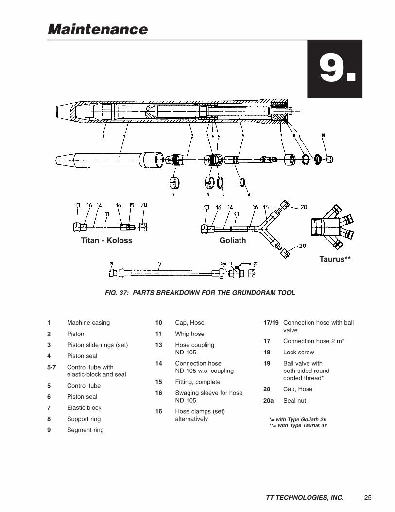
Maintenance
1 Machine casing
2 Piston
3 Piston slide rings (set)
4 Piston seal
5-7 Control tube with elastic-block and seal
5 Control tube
6 Piston seal
7 Elastic block
8 Support ring
9 Segment ring
10 Cap, Hose
11 Whip hose
13 Hose coupling ND 105
14 Connection hose ND 105 w.o. coupling
15 Fitting, complete
16 Swaging sleeve for hoseND 105
16 Hose clamps (set) alternatively
17/19 Connection hose with ballvalve
17 Connection hose 2 m*
18 Lock screw
19 Ball valve with both-sided round corded thread*
20 Cap, Hose
20a Seal nut
*= with Type Goliath 2x**= with Type Taurus 4x
Titan - Koloss Goliath
Taurus**
FIG. 37: PARTS BREAKDOWN FOR THE GRUNDORAM TOOL
9.

26 TT TECHNOLOGIES, INC.
A. Grundoram Disassembly NOTE: The following items correspond to Fig. 37. The complete control stud(Items 5, 6, 7) is pushed into the machine casing (Item 1) and is safely held inposition by means of a support ring (Item 8) and a segment ring (Item 9).
1. Removal of the control stud.
2. To remove the control stud, lay the GRUNDORAM on a support frame or onthe ground.
3. Remove the connection air hose (see Fig. 38).
4. Push the carrier cone (Item A - Fig. 39) of the clamping device over the machinebody (see Fig. 39).
5. Push the three draw rods (Item B - Fig. 39) through the holes of the Carrier Coneand attach the nuts at the Carrier Cone (Item A - Fig. 39).
6. Push the thrust piece (Item C - Fig. 39) over the connection threads of thecontrol tube.
7. Slide the clamping plate (Item D - Fig. 40) onto the three draw rods (Item B -Fig. 40).
8. Screw the nuts (Item E - Fig. 41) evenly onto the draw rods (Item B - Fig. 41)to ensure that the clamping plate (Item D - Fig. 41) is parallel to the end of themachine body.
FIG. 38: REMOVE AIR HOSE FIG. 39: CARRIER CONE & DRAWRODS OF CLAMPING DEVICE
FIG. 40: SLIDE ON CLAMPINGPLATE
FIG. 41: HYDRAULIC CYLINDER INPLACE AND CONNECTED
AB
BC
B
A
B
B
BC
D
D
E
B
B
B
F

27TT TECHNOLOGIES, INC.
9. Insert the hydraulic cylinder (Item F - Fig. 41) and ensure that the bottom of thecylinder is on the clamping plate (Item D - Fig. 41).
10. Connect the hoses of the hydraulic pump (see Fig. 41).
11. Operate the hydraulic cylinder using the manually operated pump (see Fig. 42)until the complete segment ring (Item 9) can be removed.
12. Remove components of the segment ring (see Fig. 43).
IMPORTANT: Do not touch segment grooves with hand. The hydraulic press mayfail. Use tools to remove stuck segments.
13. Remove the clamping device.
14. Remove the support ring (Item 8 - Fig. 37, also see Fig. 44).
15. Removal of the complete control stud. Fit the connection air hose to the threadof the control tube and use to help remove the complete control stud (shownwithout air hose connected) (see Fig. 45).
FIG. 44: REMOVE SUPPORT RING FIG. 45: REMOVE CONTROL STUD
FIG. 42: OPERATE HAND PUMP FIG. 43: REMOVE COMPONENTSOF SEGMENT RING

28 TT TECHNOLOGIES, INC.
B. Piston Removal 1. Remove the piston (Item 2 - Fig. 37) with a pulling hook (see Fig. 46).
2. Lift the piston using a textile strap, with a crane, fork lift or hoist. For safeworking and lifting, use appropriate lifting equipment. On removal, the pistonshould be kept parallel to the machine body to ensure that no damage is causedto slide tapes or threads (see Fig. 47).
C. Grundoram Assembly 1. Replace piston slide rings and piston seal. After removal of the main piston from
the machine body, remove the old, worn slide rings and the piston seal.
2. Clean all the grooves for replacement seals.
3. Thoroughly clean the main piston and the inner part of the machine body(see Fig. 48). Follow safety regulations when using degreaser.
4. Push the piston insertion sleeve into the hole of the machine body (see Fig. 49).
FIG. 48: THOROUGHLY CLEANPISTON AND MACHINE
FIG. 49: PUSH PISTON INSERTIONSLEEVE INTO MACHINE
FIG. 46: REMOVE PISTON WITHPULLING HOOK
FIG. 47: LIFTING PISTON WITHTEXTILE STRAP

29TT TECHNOLOGIES, INC.
5. Move the slide rings onto the groove for the rings on the piston (see Fig. 50 andFig. 51).
6. There must be a gap at the end of the slide rings (see Fig. 51 and Fig.53).
7. Finally, fit the piston seal (rubber ring and white piston seal - see Fig. 52). Thewhite piston seal shall have the same gap (see Fig. 53).
8. Once the slide rings and the piston seal have been installed, slide the piston intothe machine body.
9. Remove the piston insertion sleeve.
D. Control Stud Assembly 1. Changing the seal for the control stud. When the seal of the control stud is worn
it must be replaced.
IMPORTANT: The seal for the control stud consists of one rubber ring and onewhite cylindrical ring. (The DAVID, MINI-ATLAS, ATLAS, TITAN, MINI-OLYMPUS,and OLYMPUS have no rubber ring). Do not cut the seals apart like the piston seal.
2. Cut off and remove the worn control stud seal.
FIG. 52: INSTALL PISTON SEAL FIG. 53: PISTON SLIDE RING GAPS
FIG. 50: INSTALL FRONTSLIDE RING
FIG. 51: INSTALL REARSLIDE RING
GRUNDORAM Piston Slide RingMODEL Gap (inch)DAVID 0.15-0.20MINI-ATLAS 0.15-0.20ATLAS 0.15-0.20TITAN 0.20-0.24MINI-OLYMPUS 0.20-0.24OLYMPUS 0.30-0.39HERCULES 0.39-0.47MINI-GIGANT 0.39-0.47GIGANT 0.39-0.47KOLOSS 0.55-0.63GOLIATH 0.55-0.63TAURUS 0.55-0.63

30 TT TECHNOLOGIES, INC.
3. Fit the new control stud seal into the groove:a) First fit the rubber ring (Not applicable to the DAVID, MINI-ATLAS, ATLAS,
TITAN, MINI-OLYMPUS and OLYMPUS).b) Carefully stretch the white control stud seal and fit into the groove.
4. After fitting the complete seal into the groove, compress the seal to its originalsize using a hose clamp (see Fig. 54).
5. Position the ring and the draw rods on the machine body and insert the completecontrol stud into the piston (see Fig. 55).
NOTE: Check whether or not the elastic block (Item 7 - Fig 37) is worn. Replace ifnecessary.
6. Position the support ring (Item 8 - Fig 37). The lugs of the support ring must fitinto the holes in the elastic block (see Fig. 56 and Fig. 57).
7. Fit the clamping device (see Figs. 39-41) and connect the manually operatedhydraulic pump.
8. Compress the elastic block (Item 7 - Fig 37) using the manually operatedhydraulic pump until the single components of the segment ring (Item 9 - Fig 37)can be put into the groove (see Fig. 58).
NOTE: Ensure that the segments are put into the groove in the correct direction. Ifthe segments are worn, assemble only new segments. Only exchange the wholeset of segments. Never exchange single components.
FIG. 56: POSITION SUPPORT RING FIG. 57: SUPPORT RING IN PLACE
FIG. 54: COMPRESS WITHHOSE CLAMP
FIG. 55: INSTALL CONTROL STUDINTO PISTON

31TT TECHNOLOGIES, INC.
9. Apply grease onto the three last components of the segment ring to ease thefitting.
10. Release the pressure of the hydraulic pump.
11. Check the correct position of the single components of the segment ring.
12. Remove the complete clamping device.
13. The segment ring must be radially positioned behind the edge of the support ring (see Fig. 59).
NOTE: All components of the segment ring must be checked for the correctposition prior to each operation. If single components do not fit correctly, contactthe manufacturer or your GRUNDORAM distributor.
14. Screw on the connection air hose and secure with hammer.
15. Briefly run the machine to check the operation
16. After this test, check the position of the single components of the segment ring again.
17. The GRUNDORAM is now ready for operation.
E. Connection Air Hose Replacement1. The connection air hose is connected
via a thread to the control tube. Onlyunscrew the swivel coupling(see Fig. 60).
FIG. 58: INSTALL SEGMENT RING FIG. 59: SEGMENT RING IN PLACE
FIG. 60: REMOVE OLD AIR HOSEAND REPLACE WITH NEW ONE

32 TT TECHNOLOGIES, INC.
F. Removal and Disassembly of the Control Stud ofthe Mini-Atlas GRUNDORAM
1. The complete control stud (Items 25, 30, 40, 45, 50, 60, 65 - Fig 61) is positionedin the casing end (Item 35 - Fig 61) and is secured with a segment ring(Item 55 - Fig 61) . The casing end (Item 35 - Fig 61) itself is screwed ontothe machine casing (Item 4 - Fig 61) and is secured by metal adhesive.
2. Remove the connection air hose (see Fig. 62).
3. Move the sleeve of the assembly tool over the thread of control tube(see Fig. 63).
4. Screw the bolts of the assembly tool frame into the holes for the C-spanner at thecasing end (see Fig. 64).
5. Position the tensioning bolt of the assembly tool onto the sleeve and press theelastic block (Item 40) until the segments of the segment ring (Item 55) can beremoved easily from the groove of the casing end (Item 35 - see also Fig. 65).
6. Reduce the tension of the assembly tool and move it aside.
FIG. 61: PARTS BREAKDOWN FOR THE MINI-ATLAS GRUNDORAM TOOL
4 Machine body with knifehead and RK reception
10 Piston
15 Piston slide tapes (set)
20 Piston seal
25 Control tube for reverse runcontrol
30 Control stud seal
35 Casing end with cableconnection, without cable
40 Elastic block
45 Adjusting nut for reverse runcontrol
50 Stop nut for reverse runcontrol
55 Segment ring for reverserun control
60 Support ring for reverse runcontrol
65 Pin set (set=2 pieces)
75-100 Connection air hose,complete, 0.3 m long
75 Nozzle DN 25 with ring andspigot nut
100 Sealing cap for quick-cou-pling DN 25
15/20/30 Seals (complete set)
4-100 Mini-Atlas 130 with slottedhead, 10 degrees receptionand 1' whip hose

33TT TECHNOLOGIES, INC.
7. Remove support ring (Item 60 - see Fig. 66).
8. Pull the control stud out of the casing end (Item 35 - see Fig. 67).
9. For further control stud assembly and disassembly please contact TTTechnologies technical support personnel.
FIG. 64: ATTACH FRAMEASSEMBLY TOOL
FIG. 65: REMOVE SEGMENT RING
FIG. 62: REMOVE CONNECTIONAIR HOSE
FIG. 63: INSTALL ASSEMBLY TOOLOVER THREAD OF CONTROL TUBE
FIG. 66: REMOVE SUPPORT RING FIG. 67: REMOVE CONTROL STUD

34 TT TECHNOLOGIES, INC.
G. Mini-Atlas Piston Removal 1. Place a C-spanner on the machine body (Item 4 - Fig 61), or clamp it into the TT
Technologies, Inc. repair stand.
2. Quickly heat up the thread of the casing end to 390° F to destroy the adhesive onthe threads.
3. Position C-spanner or O-spanner at the casing end (Item 35 - Fig 61). Loosen itwith a hammer and unscrew it completely (see Fig. 68 and Fig. 69).
4. Clean all the threads while they are stillwarm using a wire brush.
5. Remove the piston with a pulling hook(see Fig. 70).
FIG. 68: LOOSEN CASING END
FIG. 70: REMOVE PISTON
FIG. 69: REMOVE CASING END

35TT TECHNOLOGIES, INC.
H. Mini-Atlas Assembly 1. Replace the piston slide rings and the piston seals. To renew the piston slide
rings and the piston seal, proceed as described in Section 9C.
2. Push the piston into the casing once piston slide rings and seals have beenreplaced (see Fig. 71).
3. Apply loctite to the threads on the casing end and tighten with a hammer(see Fig. 72, Fig. 73 and Fig. 74).
4. Allow 24 hours at 70° F for loctite to cure to full strength. If time does not allow,loctite can be force cured by heating to 250° F using a gas burner. After theinitial heating, secure the casing end (Item 35) again with a hammer onto a C-spanner. Keep a maximum temperature of 250° F for approximately 30minutes.
NOTE: Only threaded parts firmly screwed together can transmit the full power ofthe GRUNDORAM. The adhesive prevents the thread from subsequent loosening.Do not cool with water.
5. Ensure the machine has cooled down prior to being used. Do not use water tocool.
FIG. 71: INSTALL PISTON FIG. 72: APPLY LOCTITE
FIG. 73: ATTACH CASING END FIG. 74: TIGHTEN CASING END
36 TT TECHNOLOGIES, INC.
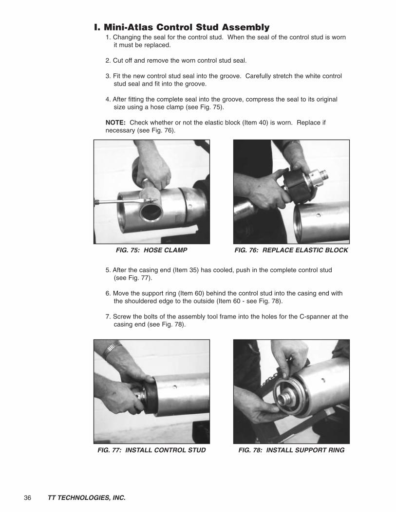
I. Mini-Atlas Control Stud Assembly 1. Changing the seal for the control stud. When the seal of the control stud is worn
it must be replaced.
2. Cut off and remove the worn control stud seal.
3. Fit the new control stud seal into the groove. Carefully stretch the white controlstud seal and fit into the groove.
4. After fitting the complete seal into the groove, compress the seal to its originalsize using a hose clamp (see Fig. 75).
NOTE: Check whether or not the elastic block (Item 40) is worn. Replace ifnecessary (see Fig. 76).
5. After the casing end (Item 35) has cooled, push in the complete control stud(see Fig. 77).
6. Move the support ring (Item 60) behind the control stud into the casing end withthe shouldered edge to the outside (Item 60 - see Fig. 78).
7. Screw the bolts of the assembly tool frame into the holes for the C-spanner at thecasing end (see Fig. 78).
FIG. 77: INSTALL CONTROL STUD FIG. 78: INSTALL SUPPORT RING
FIG. 75: HOSE CLAMP FIG. 76: REPLACE ELASTIC BLOCK

37TT TECHNOLOGIES, INC.
8. Position the tensioning bolt of theassembly tool onto the sleeve andpress the elastic block (Item 40) untilthe segments of the segment ring(Item 55) can be positioned easily inthe groove of the casing end(see Fig. 79). To assist the fitting ofthe segments assembly grease canbe applied onto the single segments.
9. Slowly reduce the tension of theassembly tool until the elastic blocksafely sits against the segment ring.
10. Remove the assembly tool.
11. For further control stud assembly and disassembly procedures please contactTT Technologies technical support personnel.
12. The Mini-Atlas GRUNDORAM can be used immediately.
J. Connection Air Hose Replacement 1. The connection air hose is connected
via a thread to the control tube. Onlyunscrew the swivel coupling(see Fig. 80).
K. Mini-Olympus and Mini-Gigant Disassembly For assembly and disassembly procedures please contact TT Technologiestechnical support personnel.
1. Replacement of the connection air hose, refer to Section 9J.
FIG. 79: INSTALL SEGMENT RING
FIG. 80: REMOVE OLD AIR HOSEAND REPLACE WITH NEW ONE
38
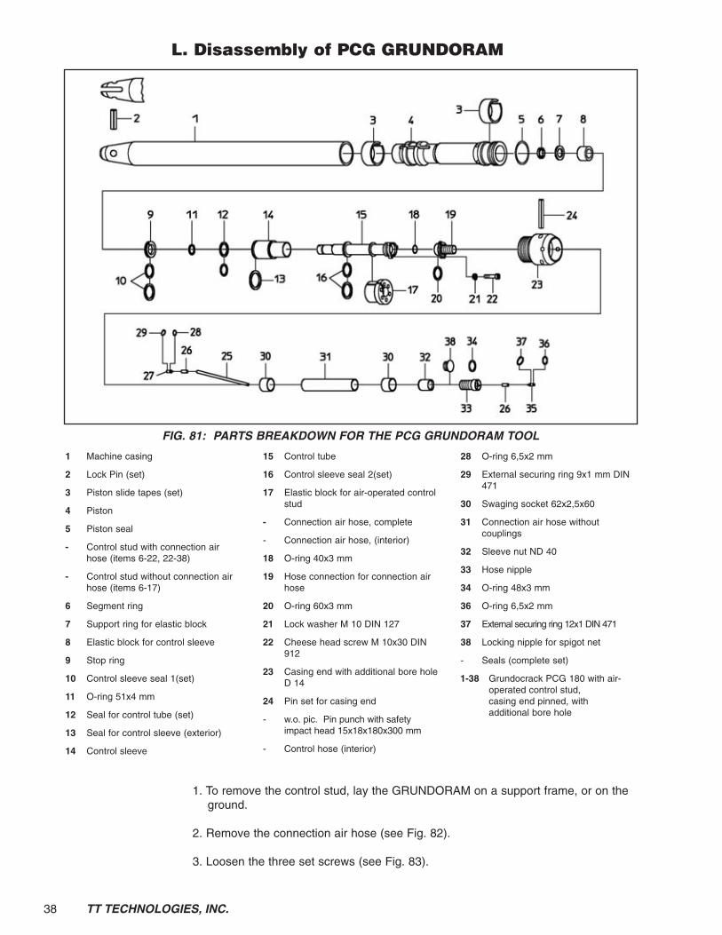
L. Disassembly of PCG GRUNDORAM
1. To remove the control stud, lay the GRUNDORAM on a support frame, or on theground.
2. Remove the connection air hose (see Fig. 82).
3. Loosen the three set screws (see Fig. 83).
TT TECHNOLOGIES, INC.
1 Machine casing
2 Lock Pin (set)
3 Piston slide tapes (set)
4 Piston
5 Piston seal
- Control stud with connection airhose (items 6-22, 22-38)
- Control stud without connection airhose (items 6-17)
6 Segment ring
7 Support ring for elastic block
8 Elastic block for control sleeve
9 Stop ring
10 Control sleeve seal 1(set)
11 O-ring 51x4 mm
12 Seal for control tube (set)
13 Seal for control sleeve (exterior)
14 Control sleeve
15 Control tube
16 Control sleeve seal 2(set)
17 Elastic block for air-operated controlstud
- Connection air hose, complete
- Connection air hose, (interior)
18 O-ring 40x3 mm
19 Hose connection for connection airhose
20 O-ring 60x3 mm
21 Lock washer M 10 DIN 127
22 Cheese head screw M 10x30 DIN912
23 Casing end with additional bore holeD 14
24 Pin set for casing end
- w.o. pic. Pin punch with safetyimpact head 15x18x180x300 mm
- Control hose (interior)
28 O-ring 6,5x2 mm
29 External securing ring 9x1 mm DIN471
30 Swaging socket 62x2,5x60
31 Connection air hose withoutcouplings
32 Sleeve nut ND 40
33 Hose nipple
34 O-ring 48x3 mm
36 O-ring 6,5x2 mm
37 External securing ring 12x1 DIN 471
38 Locking nipple for spigot net
- Seals (complete set)
1-38 Grundocrack PCG 180 with air-operated control stud,casing end pinned, withadditional bore hole
FIG. 81: PARTS BREAKDOWN FOR THE PCG GRUNDORAM TOOL

39TT TECHNOLOGIES, INC.
4. Remove the three set screws (see Fig. 84).
5. Remove cable from tool (see Fig. 85).
6. Use 2 set screws as jack screws to remove hose connection (see Fig. 86).
7. Remove the hose connection (see Fig. 87)
FIG. 84: REMOVE THREESET SCREWS
FIG. 85: REMOVE CABLEFROM TOOL
FIG. 82: REMOVE CONNECTIONAIR HOSE
FIG. 83: LOOSEN THREESET SCREWS
FIG. 86: USE TWO SET SCREWSAS JACK SCREWS
FIG. 87: REMOVE HOSECONNECTION

40 TT TECHNOLOGIES, INC.
8. Place carrier cone of the clamping device on the PCG GRUNDORAM tool(see Fig. 88).
9. Install the two rings into the groove of the tool body (see Fig. 89).
10. Position the carrier cone on top the the two rings (see Fig. 90).
11. Attach the three draw rods by screwing them into the carrier cone (see Fig. 91).
12. Slide the clamping plate onto the three draw rods, screw the nuts evenly ontothe draw rods to ensure the clamping plate is parallel to the end of the machinebody. Install the thrust piece (see Fig. 92).
FIG. 90: POSITION CARRIER CONE FIG. 91: ATTACH DRAW RODS
FIG. 88: PLACE CARRIER CONEON TOOL
FIG. 89: INSTALL TWO RINGS INGROOVE OF TOOL BODY
FIG. 92: INSTALL THRUST PIECE FIG. 93: INSTALL HYDRAULICCYLINDER

41TT TECHNOLOGIES, INC.
13. Insert the hydraulic cylinder and ensure that the bottom of the cylinder is on theclamping plate, then connect the hoses of the hydraulic pump (see Fig. 93).
14. Operate the hydraulic cylinder using the manually operated pump (see Fig. 94)until the complete segment ring can be removed.
15. Removal of the components of the segment ring (see Fig. 95)
NOTE: Do not touch segment grooves with hand. The hydraulic press may fail. Use tools to remove stuck segments.
16. Remove the hydraulic cylinder, the clamping plate and the three draw rods(see Fig. 96).
17. Remove the complete control stud (see Fig. 97).
FIG. 96: REMOVE HYDRAULICCYLINDER
FIG. 97: REMOVE CONTROL STUD
FIG. 94: OPERATE HAND PUMP FIG. 95: REMOVE SEGMENT RING

42 TT TECHNOLOGIES, INC.
18. Use the jacking rod to remove the support ring (see Fig. 98 & Fig. 99).
19. Remove the small section first, you will need to twist and turn the part to removeit from the tool (see Fig. 100). Then remove the large section (see Fig. 101).Both pieces are shown together (see Fig. 102).
20. Remove the piston with a piston hook (see Fig. 103).
FIG. 102: SHOWING TWOSECTIONS
FIG. 103: REMOVE PISTON WITHPISTON HOOK
FIG. 100: REMOVE SMALLSECTION
FIG. 101: REMOVE LARGESECTION
FIG. 98: USE JACKING ROD TOREMOVE SUPPORT RING
FIG. 99: REMOVE SUPPORT RING

43TT TECHNOLOGIES, INC.
M. Piston Assembly 1. Once the piston is removed you need to insert the insertion sleeve into the tool
in order to get the piston to slide back into the tool (see Fig. 104 and Fig. 105).
2. Now you can replace the piston seals (see Fig. 106 & 107).
3. When the piston is inserted back into the tool, then remove the insertion sleeve(see Fig. 108).
FIG. 108: REMOVE INSERTIONSLEEVE
FIG. 106: REPLACE PISTON SEALS FIG. 107: REPLACE PISTON SEALS
FIG. 104: INSERT INSERTIONSLEEVE
FIG. 105: PUSH INSERTIONSLEEVE IN
44 TT TECHNOLOGIES, INC.
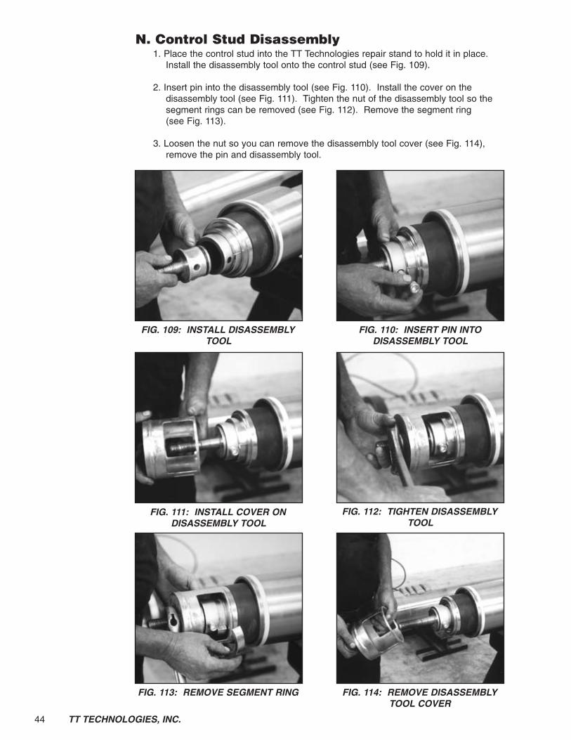
N. Control Stud Disassembly1. Place the control stud into the TT Technologies repair stand to hold it in place.
Install the disassembly tool onto the control stud (see Fig. 109).
2. Insert pin into the disassembly tool (see Fig. 110). Install the cover on thedisassembly tool (see Fig. 111). Tighten the nut of the disassembly tool so thesegment rings can be removed (see Fig. 112). Remove the segment ring(see Fig. 113).
3. Loosen the nut so you can remove the disassembly tool cover (see Fig. 114),remove the pin and disassembly tool.
FIG. 113: REMOVE SEGMENT RING FIG. 114: REMOVE DISASSEMBLYTOOL COVER
FIG. 111: INSTALL COVER ONDISASSEMBLY TOOL
FIG. 112: TIGHTEN DISASSEMBLYTOOL
FIG. 109: INSTALL DISASSEMBLYTOOL
FIG. 110: INSERT PIN INTODISASSEMBLY TOOL

45TT TECHNOLOGIES, INC.
4. Then remove the seal ring and the elastic block (see Fig. 115).
5. Remove the outer control tube section (see Fig. 116). Remove the stop ring (seeFig. 117).
6. Replace the inner control tube seal (see Fig. 118). Use a compression clamp toreform the seals (see Fig. 119 & Fig. 120).
FIG. 119: USE COMPRESSIONCLAMP TO REFORM SEAL
FIG. 120: USE COMPRESSIONCLAMP TO REFORM SEAL
FIG. 117: REMOVE STOP RING FIG. 118: REPLACE INNERCONTROL TUBE SEAL
FIG. 115: REMOVE SEAL RING ANDELASTIC BLOCK
FIG. 116: REMOVE OUTER CONTROL TUBE

46 TT TECHNOLOGIES, INC.
7. Replace the black o-ring (see Fig. 121).
O. Control Stud Assembly1. Install the outer control tube (see Fig. 122). Then you can install the sealing ring
(see Fig. 123).
2. Install the elastic block (see Fig. 124), and the seal ring (see Fig. 125).
FIG. 124: INSTALL ELASTIC BLOCK FIG. 125: INSTALL SEAL RING
FIG. 122: INSTALL OUTER CONTROL TUBE
FIG. 123: INSTALL SEALING RING
FIG. 121: REPLACE O-RING

47TT TECHNOLOGIES, INC.
3. Install the disassembly tool on the end of the control tube (see Fig. 126), installthe pin into the disassembly tool (see Fig. 127).
4. Install the disassembly tool cover and tighten the nut so the segment ring can beinstalled (see Fig. 128).
5. Install the segment ring (see Fig. 129).
IMPORTANT: Do not touch segment grooves with hand. The hydraulic press mayfail. Use tools to remove stuck segments.
FIG. 126: INSTALL DISASSEMBLYTOOL
FIG. 127: INSTALL PIN INTODISASSEMBLY TOOL
FIG. 128: TIGHTEN DISASSEMBLYTOOL
FIG. 129: INSTALL SEGMENT RING

48 TT TECHNOLOGIES, INC.
6. Once the segment ring is installed, loosen the nut to remove the disassemblytool, remove the cover, the pin and the disassembly tool. Remove the controlstud from the TT Technologies repair stand and install the control stud into themachine (see Fig. 130).
7. Attach the three draw rods by screwing them into the carrier cone. Slide theclamping plate onto the three draw rods, screw the nuts evenly onto the drawrods to ensure the clamping plate is parallel to the end of the machine body.Install the thrust piece. Insert the hydraulic cylinder and ensure that the bottomof the cylinder is on the clamping plate, then connect the hoses of the hydraulicpump. Operate the hydraulic cylinder using the manually operated pump untilthe segment ring can be installed (see Fig. 131).
8. Release the pressure on the hydraulic pump so you can remove the hydraulicpump, thrust piece, clamping plate, three draw rods carrier cone and two rings ingroove of tool body.
9. Attach hose connection to tool with three set screws (see Fig. 132). Tighten setscrews, replace cable into the groove of the tool, then attach connection air hose.
10. Specifications of the air hoses. If spare parts are required, use original spareparts for the TT companies or approved agents. The same applies to air hoses.According to the regulations, only use compressed air hoses with a minimumsafe working pressure of 145 psi.
FIG. 132: INSTALL SET SCREWS
FIG. 130: INSTALL CONTROL STUD FIG. 131: INSTALL SEGMENT RING

49TT TECHNOLOGIES, INC.
11. Function test. After assembly, check the GRUNDORAM (i.e. lay GRUNDORAMon the ground and connect it to the compressor). Open the air valve slowly andcheck if the piston reciprocates freely. Allow GRUNDORAM, operating atreduced pressure, to run in all new seals, etc., for a few minutes.
12. Remarks about the oil to be used. GRUNDO-OIL is a synthetic lubricatewith very good lubrication properties. It is odorless, non-toxic and virtuallyinflammable. GRUNDO-OIL is not harmful to synthetic materials and iscompletely biodegradable. GRUNDO-OIL is water-soluble and has anti-freezeproperties. Should you wish to use another type of oil, we recommend onlypneumatic lubricants with similar properties.

50 TT TECHNOLOGIES, INC.
10.Troubleshooting Guide
Observation Reason Solution
1. The GRUNDORAM is lackingpower. Usually the problem isthat the lubricator and moisturefrom the air compressor gum upthe inside of the barrel and theseals. Remove whip hose andpour in diesel fuel, reattach hoseand run tool. It is good practiceto clean the tool this way duringheavy use or when storing thetool during down time. Dieselfuel cuts through the moistureand helps prevent the pitting thatcan occur when water sits insidethe tool.
2. GRUNDORAM is difficult to start,after starting runs at about 50%and the air is exhausting throughthe back in an excessiveamount. Check air dischargefrom compressor, also check airdischarge temp. This will tell youhow hot the tool was running.
3. GRUNDORAM is filled withwater and silt. Do I need to takeit apart to clean it?
4. Straight Barrel Reversible ToolsOnly—Reversing GRUNDORAM,if the tool is dirty or gummed upinside it can cause the tool to runin reverse or neutral.
a) The compressor is notdeveloping its rated psi.
b) Internal piston resistance due todirt or sludge buildup.
c) Air requirements of rammer toohigh due to worn or missingseals.
d) Insufficient or incorrect type ofair tool oil.
e) Compressor dischargetemperature too high.
a) OSHA safety valve oncompressor not allowing surgeof air to start tool.
b) Seals on control stud and pistonare worn or missing, due to highair temp or lack of lubricant.High discharge pressure cancause the seals to fail also.
a) Pit was flooded before the toolwas removed.
a) Internal piston resistance due todirt or sludge buildup.
b) Reversing air line plugged or notinstalled.
a) Check air pressure at thecompressor gauge (95 to 105 psi).
b) Flush rammer with diesel fuel orcleaning solvent.
c) Disassemble rammer andinspect or replace seals.
d) Check function/setting oflubricator. Use GRUNDO-OILor approved alternative.
e) Check seals. High temps causeseals to wear faster.
a) Contact compressor servicetech for adjustment.
b) Replace worn or missing seals.Check function/setting oflubricator. Use GRUNDO-OILor approved alternative.
a) Tool normally can be cleanedwithout disassembly. Powerwash inside of tool throughcontrol stud opening or throughthe holes in the exhaust block.Lift the tool and tilt to wash anddrain. Then flush with dieselfuel or cleaning solvent.
a) Flush rammer with diesel fuel orcleaning solvent.
b) Make sure reversing air line isinstalled and open duringforward operation.

51TT TECHNOLOGIES, INC.
Warranty Information
11.DISCLAIMER FOR RAMMING MANUAL:NO WARRANTY AS TO MANUALTT Technologies makes no warranty that the information provided in this manual iscomplete, accurate in all respects, or up to date. This manual should be used as areference work to provide a starting point for addressing pipe ramming situations. Eachparticular situation is different. The user is responsible for providing the expertise andskill necessary to properly execute a given pipe-ramming job. TT Technologiesspecifically disclaims all express or implied warranties concerning this manual, includingthe implied warranties of merchantability and fitness. In no event shall TT Technologiesbe liable for consequential, special or incidental damages or contingent liabilities(including, without limitation, lost profits or goodwill, whether such claim arises in tort,contract, negligence, strict liability or any other basis) arising in any way out of the useof this manual.
LIMITED WARRANTY AS TO PRODUCTSTT provides a limited warranty to the original purchaser of its new products that newproducts will be free from defects in materials and workmanship for 90 days or 500hours of actual use, whichever occurs first, provided they are properly maintainedserviced and used for the intended purpose of the product. (A one year warrantyapplies to the barrel and piston, otherwise the period is as previously stated.) Duringthe 90 day or 500 hours period, buyer's remedies are limited to repair or replacement, atTT Technologies' discretion.
TT Technologies makes no other warranty, express or implied, and makes no warrantyof merchantability or fitness for any particular purpose. No person, representative oragent of TT Technologies has the authority to change this warranty in any mannerwhatsoever. Any oral or written statements inconsistent with this limited warranty shallnot apply.
In no event shall TT Technologies be liable for consequential, special or incidentaldamages or contingent liabilities (including, without limitation, lost profits or goodwill,whether such claim arises in tort, contract, negligence, strict liability or any other basis)arising in any way out of the use of any product or any parts thereof.

52 TT TECHNOLOGIES, INC.
12.APPENDIX
AppendixA. Parts List for 095 David
Item No Description Qty Part Number
1 Machine body 1 DF 0950150
2 Piston 1 GRU 0955141
3 Piston slide tapes (set) 1 GRU 0955130
4 Piston seal 1 GRU 0955160
5-7 Control tube with elastic block and seal ring 1 DF 0950159
5 Control tube 1 DF 0950160
6 Control stud seal (2 pcs.) 1 GRU 0956530
7 Elastic block 1 DF 0950165
8 Support ring 1 DF 0950166
9 Segment ring 1 DF 0950167
10 Lock nut 1 DF 0950121
17/19 Connection air hose with stop valve 1 AF 1300170
20 Locking coupling for Mody couplings 1 GRU 2002060
— Grundoram David 95 F complete 1 DF 0950000
— Seals, (complete set) 1 DF 0950104

53TT TECHNOLOGIES, INC.
B. Parts List for 130 Atlas
Item No Description Qty Part Number
1 Machine body 1 AF 1300150
2 Piston 1 G-Z 1305141
3 Piston slide tapes (set) 1 GRS 1305130
4 Piston seal 1 GRU 1305160
5-7 Control tube with elastic block and seal ring 1 AF 1300159
5 Control tube 1 AF 1300160
6 Control stud seal 1 A 1300107
7 Elastic block 1 AF 1300165
8 Support ring 1 AF 1300166
9 Segment ring 1 AF 1300167
w.o pic Robber buffer 1 AF 1300180
10 Lock nut 1 DF 0950121
17/19 Connection air hose with stop valve 1 AF 1300170
20 Locking coupling for Mody couplings 1 GRU 2002060
— Grundoram Atlas 130 F complete 1 AF 1300000
— Seals, (complete set) 1 AF 1300104

54 TT TECHNOLOGIES, INC.
C. Parts List for 130 Mini-Atlas
Item No Description Qty Part Number
4 Machine body with knife head and RK reception 1 AM 1300153
10 Piston 1 AM 1300103
15 Piston slide tapes (set) 1 GRS 1305130
20 Piston seal 1 GRU 1305160
25 Control tube for reverse run control 1 AM 1300156
30 Control stud seal 1 A 1300107
35 Casing end with cable connection, without cable 1 AM 1300118
40 Elastic block 1 AM 1300122
45 Adjusting nut for reverse run control 1 AM 1300121
50 Stop nut for reverse run control 1 AM 1300120
55 Segment ring for reverse run control 1 AM 1300125
60 Support ring for reverse run control 1 AM 1300128
65 Pin set (set=2 pieces) 1 AM 1300123
75-100 Connection air hose, complete, 0.3 m long 1 AM 1300160
75 Nozzle DN 25 with ring and spigot nut 1 AM 1300161
100 Sealing cap for quick-coupling DN 25 1 G-E 0902390
15, 20, 30 Seals, (complete set) 1 AM 1300115
4-100 Mini-Atlas 130 with slotted head,10 degrees receptionand 1' whip hose 1 AM 1300004

55TT TECHNOLOGIES, INC.
D. Parts List for 145 Titan
Item No Description Qty Part Number
1 Machine body 1 TF 1450150
2 Piston 1 G-E 1455141
3 Piston slide tapes (set) 1 G-E 1455130
4 Piston seal 1 G-E 1455160
5-7 Control tube with elastic block and seal ring 1 TF 1450159
5 Control tube 1 TF 1450160
6 Control stud seal 1 T 1450107
7 Elastic block 1 TF 1450165
8 Support ring 1 TF 1450166
9 Segment ring 1 TF 1450167
10 Dust cap with 55x1/6" knurled thread 1 G 2600221
17 7' air hose, complete 1 G 2600223
18 Dust plug with 55x1/6" knurled thread 1 G 2600245
19 Ball valve 55x1/6" knurled thread on both sides withlocking nuts 1 H 2200242
20 Dust cap with 55x1/6" knurled thread 1 G 2600221
20a Dust cap with 55x1/6" knurled thread 1 G 2600221
— Grundoram Titan 145 F complete 1 TF 1450000
— Seals, (complete set) 1 T 1450104

56 TT TECHNOLOGIES, INC.
E. Parts List for 180 Olympus
Item No Description Qty Part Number
1 Machine body (front thread M 60, plug) 1 OF 1800152
24 Seal plug, complete, for thread M 60 (from 01.96) 1 H 2200335
26 Pulling eye (bore-D 30) M 60, complete (from 01.96) 1 H 2200319
2 Piston 1 O 1800103
3 Piston slide tapes (set) 1 O 1800104
4 Piston seal 1 G-E 1805160
5-7 Control tube with elastic block and seal ring 1 OF 1800159
5 Control tube 1 OF 1800160
6 Control stud seal 1 O 1800107
7 Elastic block 1 OF 1800165
8 Support ring 1 OF 1800166
9 Segment ring 1 OF 1800167
10 Dust cap with 75x1/6" knurled thread 1 G 4500113
17 7' air hose 2", on both sides knurled thread connection 75x1/6" 1 G 4500381
18 Dust plug with 75x1/6" knurled thread 1 G 4500245
19 Ball valve 1 1/2", on one side 55x1/6",on the other side 75x1/6" knurled thread connection 1 HF 2200241
20 Dust cap with 55x1/6" knurled thread 1 G 2600221
20a Dust cap with 75x1/6" knurled thread 1 G 4500113
— Grundoram Olympus 180 F complete (front thread M 60, plug) 1 OF 1800005
— Seals, (complete set) 1 O 1800109

57TT TECHNOLOGIES, INC.
F. Parts List for 180 Mini-Olympus
Item No Description Qty Part Number
1 Machine body with thread M 60x3 and vent plug 1 OM 1800157
w.o. pic. Seal plug, complete, for thread M 60 1 H 2200335
w.o. pic. Pulling eye (bore-D 30) M 60, complete 1 H 2200319
2 Piston 1 OM 1800103
3 Piston slide tapes (set) 1 OM 1800104
4 Piston seal 1 G-E 1805160
5 Control tube for reverse run control 1 OM 1800156
6 Control stud seal 1 O 1800107
7 Casing end 1 OM 1800125
8 Dust cap with 55x1/6" knurled thread 1 G 2600221
9 Stop ring for reverse run control 1 OM 1800119
10 Stop nut for reverse run control 1 OM 1800120
11 Adjusting nut for reverse run control 1 OM 1800121
12 Aeration block semi-shells (set=2 halves) 1 OM 1800122
13 Pin set (set=2 pieces) 1 OM 1800123
w.o. pic. Connection whip hose 7', complete without ball valve 1 G 2600223
w.o. pic. Dust plug with 55x1/6" knurled thread 2 G 2600245
w.o. pic. Ball valve 55x1/6" knurled thread on both sides with dust caps 1 H 2200242
w.o. pic. Dust cap with 55x1/6" knurled thread 2 G 2600221
no pos. Seals, (complete set) 1 OM 1800115
w.o. pic. Mini-Olympus 180 with 10 degrees reception, thread M 60x3 1 OM 1800005

58 TT TECHNOLOGIES, INC.
G. Parts List for 220 Hercules
Item No Description Qty Part Number
1 Machine body (front thread M 60, plug) 1 HF 2200152
24 Seal plug, complete, for thread M 60 (from 01.96) 1 H 2200335
26 Pulling eye (bore-D 30) M 60, complete (from 01.96) 1 H 2200319
2 Piston 1 H 2200103
3 Piston slide tapes (set) 1 H 2200104
4 Piston seal 1 H 2200105
5-7 Control tube with elastic block and seal ring 1 HF 2200159
5 Control tube 1 HF 2200160
6 Control stud seal 1 H 2200107
7 Elastic block 1 HF 2200165
8 Support ring 1 HF 2200166
9 Segment ring 1 HF 2200167
10 Dust cap with 75x1/6" knurled thread 1 G 4500113
17 7' air hose 2", on both sides knurled thread connection 75x1/6" 1 G 4500381
18 Dust plug with 75x1/6" knurled thread 1 G 4500245
19 Ball valve 1 1/2", on one side 55x1/6",on the other side 75x1/6" knurled thread connection 1 HF 2200241
20 Dust cap with 55x1/6" knurled thread 1 G 2600221
20a Dust cap with 75x1/6" knurled thread 1 G 4500113
— Grundoram Hercules 220 F complete (front thread M 60, plug) 1 HF 2200005
— Seals, (complete set) 1 H 2200111

59TT TECHNOLOGIES, INC.
H. Parts List for 260 Gigant
Item No Description Qty Part Number
1 Machine body (front thread M 90, plug) 1 GF 2600152
24 Seal plug, complete, for thread M 90 1 703249
26 Pulling eye (bore-D 30) M 90, complete 1 G 266032
2 Piston 1 G 2600103
3 Piston slide tapes (set) 1 G 2600104
4 Piston seal 1 G 2600105
5-7 Control tube with elastic block and seal ring 1 GF 2600159
5 Control tube 1 GF 2600160
6 Control stud seal 1 G 2600107
7 Elastic block 1 GF 2600165
8 Support ring 1 GF 2600166
9 Segment ring 1 GF 2600167
10 Dust cap with 75x1/6" knurled thread 1 G 4500113
17 7' connection air hose 2", on both sides knurled thread connection 75x1/6" 1 G 4500381
18 Dust plug with 75x1/6" knurled thread 1 G 4500245
19 Ball valve 75x1/6" knurled thread on both sides with locking nuts 1 G 4500217
20 Locking nut with 75x1/6" knurled thread 1 G 4500113
20a Locking nut with 75x1/6" knurled thread 1 G 4500113
— Grundoram Gigant 260 F complete (front thread M 90, plug) 1 GF 2600005
— Seals, (complete set) 1 G 2600115

60 TT TECHNOLOGIES, INC.
I. Parts List for 260 Mini-Gigant
Item No Description Qty Part Number
1 Machine body with bore hole, plug and RK reception 1 on request (4)
w.o. pic. Seal plug, complete, for thread M 80 1 G 2600331
w.o. pic. Pulling eye (bore-D 30) M 80, complete 1 G 2600319
w.o. pic. Lock pin (set) 1 PAA 1300110
2 Piston 1 GM 2600103
3 Piston slide tapes (set) 1 GM 2600104
4 Piston seal 1 G 2600105
5 Control tube for reverse run control 1 GM 2600156
6 Control stud seal 1 G 2600107
7 Casing end 1 GM 2600118
8 Locking nut with 75x1/6" knurled thread 1 G 4500113
9 Stop ring for reverse run control 1 GM 2600119
10 Stop nut for reverse run control 1 GM 2600120
11 Adjusting nut for reverse run control 1 GM 2600121
12 Aeration block semi-shells (set=2 halves) 1 GM 2600122
13 Pin set (set=2 pieces) 1 GM 2600123
w.o. pic Dust plug with 75x1/6" knurled thread 2 G 4500245
w.o. pic Ball valve 75x1/6" knurled thread on both sides with locking nuts 1 G 4500217
w.o. pic Dust cap with 75x1/6" knurled thread 2 G 4500113
no pos. Seals, (complete set) 1 GM 2600115
— Mini-Gigant 260 with 10 degrees reception 1 GM 2600005

61TT TECHNOLOGIES, INC.
J. Parts List for 350 Koloss
Item No Description Qty Part Number1 Machine body (front thread M 100, plug) 1 KF 350015224 Seal plug, complete, for thread M 100 (from 05/97) 1 GF 450033126 Pulling eye M 100 with screw (set) (from 05/97) 1 GF 4500319
w.o. pic. Screw with nut (set) for towing eye (from 05/97) 1 GF 4500323w.o. pic. Lock pin (set) (until 04/97) alternative 1 PAA 1300110w.o. pic. Lock pin (set) for towing eye (from 05/97 alternative) 1 GF 4500322
2 Piston 1 K 35001033 Piston slide tapes (set) 1 K 35001044 Piston seal 1 K 3500105
5-7 Control tube with elastic block and seal ring 1 KF 35001595 Control tube 1 KF 35001606 Control stud seal 1 K 35001077 Elastic block 1 KF 35001658 Support ring closed 1 KF 3500166A9 Segment ring 1 KF 3500167
10 Dust cap, steel 1 GF 4500168
11 Connection whip hose, complete 1 KF 350010013 Hose coupling ND 105 1 KF 350010114 Connection air hose DN 105, blank 1 G 450011116 Swaging socket for hose ND 105 1 KF 350010316 Hose clips (set) alternative 1 G 450011017 2 meter connection air hose 2", on both sides knurled
thread connection 75x1/6" 1 G 4500381
18 Dust plug with 75x1/6" knurled thread 1 G 4500245
19 Ball valve 75x1/6" knurled thread on both sides with locking nuts 1 G 4500217
20 Dust cap with 75x1/6" knurled thread 1 G 4500113
20a Dust cap with 75x1/6" knurled thread 1 G 4500113
— Grundoram Koloss 350 F complete (front thread M 100, plug) 1 KF 3500005— Seals, (complete set) 1 K 3500109
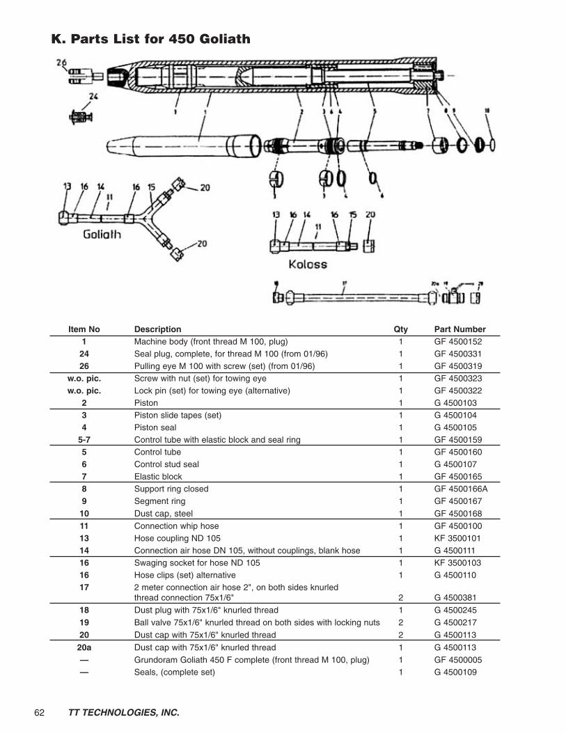
62 TT TECHNOLOGIES, INC.
K. Parts List for 450 Goliath
Item No Description Qty Part Number1 Machine body (front thread M 100, plug) 1 GF 450015224 Seal plug, complete, for thread M 100 (from 01/96) 1 GF 450033126 Pulling eye M 100 with screw (set) (from 01/96) 1 GF 4500319
w.o. pic. Screw with nut (set) for towing eye 1 GF 4500323w.o. pic. Lock pin (set) for towing eye (alternative) 1 GF 4500322
2 Piston 1 G 45001033 Piston slide tapes (set) 1 G 45001044 Piston seal 1 G 4500105
5-7 Control tube with elastic block and seal ring 1 GF 45001595 Control tube 1 GF 45001606 Control stud seal 1 G 45001077 Elastic block 1 GF 45001658 Support ring closed 1 GF 4500166A9 Segment ring 1 GF 4500167
10 Dust cap, steel 1 GF 4500168
11 Connection whip hose 1 GF 450010013 Hose coupling ND 105 1 KF 350010114 Connection air hose DN 105, without couplings, blank hose 1 G 450011116 Swaging socket for hose ND 105 1 KF 350010316 Hose clips (set) alternative 1 G 450011017 2 meter connection air hose 2", on both sides knurled
thread connection 75x1/6" 2 G 4500381
18 Dust plug with 75x1/6" knurled thread 1 G 4500245
19 Ball valve 75x1/6" knurled thread on both sides with locking nuts 2 G 4500217
20 Dust cap with 75x1/6" knurled thread 2 G 4500113
20a Dust cap with 75x1/6" knurled thread 1 G 4500113
— Grundoram Goliath 450 F complete (front thread M 100, plug) 1 GF 4500005— Seals, (complete set) 1 G 4500109

63TT TECHNOLOGIES, INC.
L. Parts List for 600 Taurus
Item No Description Qty Part Number1 Machine body (front thread M 100, plug) 1 TF 600015224 Seal plug, complete, for thread M 100 1 GF 450033126 Pulling eye M 100 with screw (set) 1 GF 4500319
w.o. pic. Screw with nut (set) for towing eye 1 GF 4500323w.o. pic. Lock pin (set) for towing eye (alternative) 1 GF 4500322
2 Piston 1 TF 60001033 Piston slide tapes (set) 1 TF 60001044 Piston seal 1 TF 6000105
5-7 Control tube with elastic block and seal ring 1 TF 60001595 Control tube 1 TF 60001606 Control stud seal 1 TF 60001077 Elastic block 1 TF 60001658 Support ring closed 1 TF 6000166A9 Segment ring 1 TF 6000167
10 Dust cap, steel 1 TF 6000168
13-16 Connection whip hose, complete 1 TF 600010113 Hose socket for hose coupling 2 TF 600017114 Connection air hose, blank 1 TF 600011115 Spigot nut for hose coupling 2 TF 600017016 Hose clips (pair) 2 TF 600011017 Connection T-piece, complete (incl. 1x Item 10 and 4x Item 18) 1 TF 6000102
18 Dust cap with 75x1/6" knurled thread 4 G 4500113
19 Ball valve 75x1/6" knurled thread on both sides with locking nuts 4 G 4500217— Grundoram Taurus 600 F complete (front thread M 100, plug) 1 TF 6000005— Seals, (complete set) (item 3, 4, 6) 1 TF 6000109

TT TECHNOLOGIES, Inc.2020 East New York Street • Aurora, IL 605041-630-851-8200 • 1-800-533-2078 • FAX 1-630-851-8299Internet http://www.tttechnologies.com • Email: [email protected] Printed in USA
TTTGRAMUG 3/02© Copyright 2002 TT TECHNOLOGIES, Inc.
®