PNEUMATIC ELECTRIC TIRE CHANGER •OPERATOR’S MANUAL - snapon.com · This tyre changer is...
56
STC 5545 PNEUMATIC ELECTRIC TIRE CHANGER DÉMONTE-PNEUS ÉLECTRO-PNEUMATIQUE ELEKTROPNEUMATISCHE REIFENMONTIERMASCHINE •OPERATOR’S MANUAL •NOTICE D’ UTILISATION •BETRIEBSANLEITUNG
Transcript of PNEUMATIC ELECTRIC TIRE CHANGER •OPERATOR’S MANUAL - snapon.com · This tyre changer is...

STC 5545
PNEUMATIC ELECTRIC TIRE CHANGER
DÉMONTE-PNEUS ÉLECTRO-PNEUMATIQUE
ELEKTROPNEUMATISCHE REIFENMONTIERMASCHINE
•OPERATOR’S MANUAL
•NOTICE D’ UTILISATION
•BETRIEBSANLEITUNG

ii
All Information in this manual has been supplied by the indicated Snap-on Technical Department:Toutes les informations fi gurant dans le présent manuel ont été fournies par le Bureau Technique indiqué :
Alle in diesem Handbuch enthaltenen Informationen wurden durch das angegebene Technische Büro von Snap-on geliefert:Вся информация, содержащаяся в данном руководстве, была доставлена по указанному технической офисе Snap-on:
Tutte le informazioni contenute in questo manuale sono fornite dall’Uffi cio Tecnico Snap-on indicato:Todas las informaciones contenidas en este manual han sido facilitadas por el Servicio Técnico Snap-on indicado:
Todas as informações contidas neste manual foram fornecidas pelo Servicio Técnico Snap-on indicado:
Snap-on Equipment Srl a unico socio
Via Provinciale per Carpi, 3342015 CORREGGIO (RE) ITALYTel.: +39-(0)522-733480Fax: +39-(0)522-733479
E-mail: [email protected]: http://www.snapon-equipment.eu
Correggio (RE) - ITALYFrancesco Frezza
date:
ENG - complies with all the relevant regulations in the following directives:FRA - est conforme à toutes les dispositions pertinentes des directives suivantes :DEU - Allen zu folgenden Richtlinien gehörenden Bestimmungen entspricht:ITA - è conforme a tutte le disposizioni pertinenti delle seguenti direttive: POR - satisfaz todas as disposições relevantes das seguintes directivas:SPA - es conforme con todas las disposiciones pertinentes a las siguientes directivas:ALB - është konform me të gjitha dispozitat që kanë të bëjnë me direktivat e mëposhtme:BUL - ����������! "! ��#$%# &!'(�&�)*#, ��)�&+!.# �� � �/�)�!.#�� )#&�%�#�#:CES - vyhovuje v�em po�adavk0m, které se vztahují na následující sm1rnice:HRV - udovoljava svim relevantnim odredbama slijede2ih smjernica:DAN - er i overensstemmelse med bestemmelserne i følgende direktiver:EST - vastab järgmiste direktiivide kõikidele asjassepuutuvatele sätetele:FIN - on seuraavien direktiivien asiaankuuluvien säännösten mukainen:ELL - 34567 89;<=5> ;3 ?@3J K7J MQ>W@XY37J 8Z3K7[XJ ;3 K7J 6[?@>\]3J >^_`43J:ISL - er í samræmi við allar viðeigandi tilskipanir eftirfarandi reglugerða:LAV - atbilst visiem attiecxgajiem noteikumiem �{d{s direktxv{s:LIT - atitinka visus toliau nurodyt| direktyv| reikalavimus:}~D - � �� ���/!�"��� �� �#�� "�&�# �) �/�)"#�� )#&�%�#�#:}ON - je u skladu sa svim relevantnim odredbama slede2ih direktiva:NLD - overeenstemt met alle toepasselijke voorschriften van de volgende richtlijnen:POL - jest zgodna �jest zgodny� ze wszystkimi zarz�dzeniami zawartymi w nast�puj�cych dyrektywach:RU} - este fabricat în conformitate cu toate prevederile în materie din urmãtoarele directive:SLO - vyhovuje v�etkým po�iadavkám, vz�ahujúcim sa na nasledujúce smernice:SLV - v skladu z vsemi predpisi, ki se nana�ajo na naslednje direktive:S�E - överensstämmer med alla bestämmelser tillhörande följande direktiv:TUR - a�a��da belirtilen yönetmeliklere ili�kin tüm hükümlere uygundur:HUN - megfelel a következ� irányelvekbe foglalt, valamennyi rendelkezésnek:RUS - ������������� ���� (&#��"����� "�&�!� �/�)��.#� )#&�%�#�:
ENG-The }anager of the Technical Of� ce is authorised to compile a technical lea� et in compliance with appendi� VII, letter A, of the ��������CE directive FRA-Le Responsable du Bureau Technique est autorisé à constituer le fascicule technique visé sous l¡anne�e VII lettre A de la directive ��������CE DEU-Der Leiter der technischen Abteilung ist bevollmächtigt, die technischen Unterlagen zu erstellen �siehe Anhang VII, Buchstabe A der Richtlinie ��������CE ITA-Il Responsabile dell¡Uf� cio Tecnico è autorizzato a costituire il fascicolo tecnico di cui all¡allegato VII lettera A della direttiva ��������CE POR-O Responsável do Gabinete Técnico está autorizado a compilar o processo técnico, referido no ane�o VII alínea A da directiva ��������CE SPA-El Responsable del Departamento Técnico está autorizado a constituir el fascículo técnico indicado en el ane�o VII letra A de la directiva ��������CE ALB-Përgjegjësi i ¢yrës Teknike është i autorizuar të realizojë fashikullin teknik sipas dokumentit bashkëngjitur VII germa A e direktivës ��������~E BUL-£�����&"#%�� "! ¤��"#$��%#� ��)�/ � �(�/"���.�" )! ����!�# ���"#$��%!�! *&�¥�&! � ����������#� � ¦&#/�+�"#� VII, §A¨, ©#&�%�#�! ��������Eª CES-¢odpov1dný pracovník technického odd1lení je oprávn1ný vypracovat technickou dokumentaci podle p«ílohy VII ¬ásti A Sm1rnice ��������ES HRV-Odgovorna osoba Tehni¬kog ureda je ovla�tena ustrojiti tehni¬ki svezak kako se vidi u dodatku VII slovo A smjernice ��������CE DAN-Chefen i den tekniske afdeling har tilladelse til udarbejdelse af den tekniske dokumentation jf bilag VII litra A i direktivet ��������EF EST-Tehnoosakonna vastutav töötaja on volitatud koostama tehnilise toimiku vastavalt direktiivi ��������EÜ VII lisa osale A FIN-Teknisen toimiston vastuuhenkilö on valtuutettu kokoamaan tekninen eritelmä direktiivin ��������E liitteen VII kohdan A mukaisesti ELL-® ̄ M39]\5>J K>\ °3Z57[>9 ±Q6<34>\ 34567 3²>\87>^>K_;X5>J 56 M6Q³²37 K>5 K3Z57[? <³[3@> 89;<=56 ;3 K> 8\5_;;X5> VII ̀ Q³;;6 A K_J >^_`46J ��������´µ ISL-Ábyrgðarmanni tækniskrifstofunnar er heimilt að gera tækniskjalið samkvæmt A-lið VII viðauka í reglugerð ��������EB LAV-Tehnisk{s noda¶as vadxt{js ir pilnvarots sast{dxt tehnisko dokument{ciju atbilsto�i ES direktxvas ��������E~ VII pielikuma A ieda¶ai LIT-u� technin· skyri| atsakingas asmuo yra ·galiotas sudaryti technin� byl�, kurios sudarymo tvarka nurodyta Direktyvos ��������EB VII priedo A dalyje }~D-£)����&"#�� "! ���"#$%#�� �))�/ � ��/!���" )! �� ����!�# ���"#$%#�� (&#&!$"#% )!)�" �� (&#/�� VII (#��� A �) )#&�%�#�!�! ��������CE }ON-Odgovorno lice Tehni¬kog ureda je ovla�teno da sastavi tehni¬ku fasciklu kako se vidi u dodatku VII slovo A direktive ��������CE NLD-Het Hoofd van de Technische Afdeling is gemachtigd om het technisch dossier samen te stellen waarover in Bijlage VII, afdeling A, van de richtlijn ��������EG POL-~ierownik Biura Projektowego jest upowa¸niony do za¹o¸enia skoroszytu technicznego, o którym mowa w ¢a¹�czniku VII litera A dyrektywy ��������UE RU}-Responsabilul Biroului Tehnic este autorizat sã întocmeascã dosarul tehnic prevãzut în ane�a VII litera A directiva ��������CE privind echipamentele tehnice SLO-¢odpovedný pracovník technického oddelenia je oprávnený vypracova� technickú dokumentáciu podºa prílohy VII ¬asti A Smernice ��������ES SLV-Vodja tehniènega urada je poobla�èena za sestavo tehniène mape, kot navedeno v prilogi VII, èrka A direktive ��������ES S�E-Ansvarig på det tekniska kontoret har behörighet att sammanställa medföljande teknisk dokumentation i enlighet med avsnitt A i bilaga VII i direktiv ��������EG TUR-Teknik Ofis Sorumlusu ��������EC önetmeli�i¡nin VII ekinin A harfinde belirtilen teknik dosyay� haz�rlamaya yetkilidir HUN-A }»szaki Iroda Irodavezet�je feljogosított a ��������E~ irányelv A részének VII }ellékletében meghatározott, m»szaki dokumentáció összeállításáraRUS-¼�%���)#��/½ ���"#$��%��� ��)�/! �(�/"���$�" ����!�#�½ ���"#$��%#¾ /#�� � ����������## � (&#/�+�"#�� VII, /#��& A )#&�%�#�� ��������CE
ITA-Direttore Operativo SPA-Director Operativo POR-Director Operacional ENG-Operations }anager FRA-Directeur Opérationnel DEU-Betriebsleiter ALB-Drejtori Operativ BUL-£(�&!�#��" )#&�%��& CES-Výkonný «editel HRV-Operativni direktor DAN-Driftsleder EST-Tegevdirektor FIN-Operatiivinen johtaja ELL-´M7Z37Q_876[?J ¿73\]\5KÀJ ISL-Starfandi framkvæmdarstjóri LAV-Operatxvais direktors LIT-Operacij| vadovas }~D-£(�&!�#��" )#&�%��& }ON-Operativni direktor NLD-Operationeel directeur POL-Dyrektor Operatywny RU}-Director Operator SLO-Výkonný riaditeº SLV-Operativni vodja S�E-Driftledare TUR-Â�letme }üdürü HUN-Operatív Igazgató RUS - Ã(&!�/��.#¾ (&�#'��)�����
2006/42/CE
2014/35/CE
2014/30/CE
ENG - DECLARATION OF CE CONFORMITYFRA - DECLARATION CE DE CONFORMITEDEU - KONFORMITÄTSERKLÄRUNGFIN - EY-VAATIMUSTENMUKAISUUSVAKUUTUSNLD - VERKLARING VAN OVEREENSTEMMINGSWE - EG-FÖRSÄKRAN OM ÖVERENSSTÄMMELSEDAN - EF-OVERENSSTEMMELSESERKLÆRINGISL - EB-SAMRÆMISYFIRLÝSINGPOL - DEKLARACJA ZGODNO�CI �CE�RUM - DECLARA�IE DE CONFORMITATE CU NORMELE CESLO - ES VYHLÁSENIE O ZHODESLV - IZJAVA O SKLADNOSTI CEALB - DEKLARATË KONFORMITETI KEHUN - EK MEGFELEL�SÉGI NYILATKOZAT
DICHIARAZIONE CE DI CONFORMITA� - ITADECLARAÇÃO CE DE CONFORMIDADE - POR
DECLARACIÓN CE DE CONFORMIDAD - SPA���!"#"$%& '" ()*+,�+(+,%� - BUL
ES PROHLÁ�ENÍ O SHOD. - CESDEKLARACIJA CE O PODOBNOSTI - HRV
EÜ VASTAVUSDEKLARATSIOON - EST/01230 CE 34556782303 - ELL
ES ATBILST9BAS DEKLAR:CIJA - LAVATITIKTIES DEKLARACIJA - LIT
�EC� ���!"#"$%;" '" (**<#"'=*(+ - MKDDEKLARACIJA CE O USKLA>ENOSTI - MON
EC UYGUNLUK BEYANNAMES? - TUR���!"#"$%& (**+,�+(+,%& (+"=�"#+"@ �( - RUS
Snap-on Equipment Srl - Via Provinciale per Carpi, 33 - 42015 Correggio (RE) Italy
ENG - takes full responsibility for declaring that the machineQ FRA - déclare sous sa propre responsabilité que la machine Q DEU - erklärt auf eigene VerantwortungX dass die MaschineQ ITA - dichiara sotto la propria responsabilità che la macchinaQ POR - declara sob a própria responsabilidade que a máquinaQ SPA - declara bajo su propia responsabilidad que la máquinaQ ALB - deklaron nën përgjegjësinë e tij se makineriaQ BUL - [\]^_`v`_ xz[ z{|z}z`~z�{X �\ �_�v~_{_Q CES - prohla�uje na �lastní �odpo��dnostX �e strojní �a�í�eníQ HRV - i�ja�ljuje pod �lastitom odgo�orno��u da strojQ DAN - erklærer på eget ans�arX at maskinenQ EST - kinnitab omal �astutuselX et aparaatQ FIN - �akuuttaa omalla �astuullaanX että koneQ ELL - ������� �������� ¡� � ¢�£��¤Q ISL - lýsir þ�í y¥ r á eigin ábyrgð að bíllinnQ LAV - ap�in¦damies sa�u atbild§bu apliecinaX ka ma�§na¨iek¦rtaQ LIT - prisiimdama atsakomyb© skelbiaX kad ma�inaQ MKD - vª«_}¬}_ xz[ �}z«_ z[|z}z`~z�{ [\]_ �_�v~_{_Q MON - i�ja�ljuje pod �lastitom odgo�oro��u da ma�inaQ NLD - �erklaart �oor eigen �erantwoordelijkheid dat de machineQ POL - owiadc�a na w®asn¯ odpowied�ialno�X °e mas�ynaQ RUM - declarã pe propria rãspundere cã ma±inaQ SLO - �yhlasuje na �lastnú �odpo�ednos²X �e strojo�é �ariadenieQ SLV - pod lastno odgo�ornostjo i�ja�ljamoX da je strojQ SWE - försäkrar under eget ans�ar att maskinenQ TUR - kendi sorumlulu³u alt´nda makinenin a±a³´da belirtilen yönetmeliklere uygun oldu³unu beyan etmektedirQ HUN - a saját felelµssége tudatában kijelentiX hogy a gépQ RUS - � xz^~z¶ z{}\{�{}\~~z�{·¸ ª_¹}^¹\{ �{z �_�v~_
TIRE CHANGERDEMONTE-PNEUS
REIFENMONTIERMASCHINESMONTAGOMME
DEMONTADORA DE PNEUSDESMONTADOR DE NEUMÁTICOS
ÇMONTUESE GOMASH!"#$%" &" '(!)%*"+ %" ,.!$
ZOUVA/KA PNEUMATIKDEMONTIRA/ GUMA
DÆKAFMONTERINGSMASKINEREHVIVAHETUSSEADE
RENKAANVAIHTOKONE012314 5657894:4 5981;53501<
AFFELGUNARVÉLRIEPU MONTÂÞAS IEKÂRTA
PADANGØ KEITIMO PRIETAISAS'(!)%*$="> %" ,.!$
DEMONTIRKA GUMABANDENLICHTER
URZ?DZENIE DO ZDEJMOWANIA OPONDISPOZITIV DE DEMONTAT CAUCIUCURI
VYZÚVA/KA PNEUMATÍKSNEMALEC GUM
DÄCKMONTERINGSMASKINLAST@K SÖKÜCÜGUMISZERELQ
#$%)!)%*"+%X[ \*"%)]
EC DECLARATION (Original document contained in Spare Parts Booklet)
DECLARATION CE (Le document original fi gurant dans le Liste des pièces détachées)
CE KONFORMITÄTSERKLÄRUNG (Originaldokument in der Ersatzteilliste enthaltenen)
ДЕКЛАРАЦИЯ EC (Оригинал документа прилагается к ведомости запчастей)
DICHIARAZIONE CE (Originale contenuta nel Libretto Ricambi)
DECLARACIÓN CE (El original se encuentra en tabla de repuestos)
DECLARAÇÃO CE (O original está contida em Lista de peças)
STC 5545
- ФАКСИМИЛЕ -

iii
DOCUMENTAZIONE DISPONIBILE
DOCUMENTAÇÃO DISPONÍVEL
DOCUMENTACIÓN DISPONIBLE
DOCUMENTATION AVAILABLEDOCUMENTATION DISPONIBLE
VERFÜGBARE DOKUMENTATIONДОСТУПНАЯ ДОКУМЕНТАЦИЯ
ABB. DESCRIPTION CODE LANGUAGESIGLE DESCRIPTION CODE LANGUE KENN. BESCHREIBUNG CODE SPRACHE
SIGLA DESCRIZIONE CODICE LINGUASIGLA DESCRIPCIÓN CÓDIGO IDIOMASIGLA DESCRIÇÃO CÓDIGO IDIOMA
:date of first publication
:date de la première édition
:Datum der Erstveröffentlichung
:data di prima pubblicazione
:fecha de la primera publicación
:data da primeira publicação
:дата первой публикации
:Product aid publicationTIRE CHANGER
:publication de support au produitDEMONTE PNEUS
:Zum Produkt gehörendes DokumentREIFENMONTIERGERÄT
:Пособие для работы с изделиемШИНОМОНТАЖНЫЙ СТАНОК
:Pubblicazione di supporto al prodottoSMONTAGOMME
:Documentação de apoio ao produtoMÁQUINA DE DESMONTAR PNEUS :publicación de soporte al producto
DESMONTA RUEDAS
Original language edition in: ITALIAN
Langue d’origine de la publication: ITALIEN
Originalausgabe in: ITALIENISCH
Edizione di lingua originale in: ITALIANO
Edición original en idioma: ITALIANO
Edição original em: ITALIANO
язык оригинального издания: АНГЛИЙСКИЙ
NOTES REGARDING DOCUMENTATION - ENG
NOTES SUR LA DOCUMENTATION - FRA
ANMERKUNGEN ZUR DOKUMENTATION - DEU
NOTE SULLA DOCUMENTAZIONE - ITA
NOTAS SOBRE A DOCUMENTAÇÃO - POR
NOTAS SOBRE LA DOCUMENTACIÓN - SPA
DICHIARAZIONE CEEC DECLARACIÓN CE
DECLARAÇÃO CE
Schema ElettricoWD Esquema Eléctrico
Esquema Eléctrico
Contenuto in SPIntegradas en SPConteúdos em SP
Contained in SPTeil der SP
Contenu dans SPСодержится в каталоге запчастей
EC DECLARATIONEC CE KONFORMITÄTSERKLÄRUNG
DECLARATION CEДЕКЛАРАЦИЯ ЕС
Wiring DiagramWD Schaltplan
Schéma électrique Схема электрических соединений
Operator’s Manual Manuel de l’Opérateur
OM Betriebsanleitung Руководство по эксплуатации
Spare Parts Booklet SP Liste des pièces détachées
Ersatzteilliste
Safety and Quick StartSécurité et Démarrage Rapide
OM Sicherheit und schneller StartБезопасность и быстрый запуск
OM Accessories Plan
Manuale OperatoreOM Manual de Operador
Manual do Operador
Libretto Ricambi SP tabla de repuestos
Lista de peças
Sicurezza e Avvio RapidoOM Segurança e Arranque Rápido
Seguridad y Arranque Rápido
OM Accessories Plan
05 / 2016

4
UPDATING REPORTS
0
Revision A of May 2016
First document issue PCN: 16G0151
Cod.: EAZ0103G20A
Safety rules are highlighted in grey.
Contents Page
1. General .............................................................. 5
2. Installation and connection ............................... 13
3. Bead breaking .................................................. 25
4. Clamping wheels .............................................. 29
5. Adjusting the mounting/demounting tool .......... 33
6. Demounting and mounting basics .................... 37
7. Demounting a tyre ............................................ 39
8. Mounting a tyre ................................................. 41
9. Infl ating a tyre ................................................... 45
10. Maintenance ..................................................... 51
11. Technical specifi cations .................................... 53
12. Disposing of the unit ......................................... 55
1.
1.1
General
Tips for the reader
Special symbols are used in this manual to facilitate
reading and understanding of pictures and written
instructions:
� Bullets indicate where an action/operation is
required.
Arrow indicating important information.
Arrow showing the direction of a
movement.
1.2 Scope
This tyre changer is designed to demount and mount
tyres with a diameter of between 10 and 24”.
Tyres can only be infl ated on the machine up to 3.3
bars.
Tyres which require a higher pressure must be
infl ated in suitable infl ating devices (safety cage and
the like).
Clamping ranges for outer and inner clamping are:
10 to 24” rim diameterOuter clamping
Inner clamping 12 to 24” rim diameter
Accessories A series of accessories are normally available for the
machine. All the accessories are listed in the attached
document (fi g. 0):
ACCESSORIES PLAN
Code: See Fig. 0
• Use the codes in the list for the purchase orders.

5
Mit Raster unterlegte Texte sind Sicherheitshinweise.
Inhalt Seite
1. Allgemeines ........................................................ 42. Aufstellen der Maschine .................................. 123. Abdrücken eines Reifens ................................ 244. Aufspannen der Räder .................................... 285. Einstellen des Montierkopfes .......................... 326. Grundsätzliche Hinweise zur Montage und
Demontage eines Reifens ............................... 367. Demontieren eines Reifens3 .............................. 88. Montieren eines Reifens ................................... 409. Füllen der Reifen .............................................. 4410. Wartung ............................................................ 5011. Technische Daten ............................................ 5212. Entsorgung ...................................................... 54
1. Allgemeines
1.1 Hinweise für den LeserIn dieser Betriebsanleitung verwendete Merkhilfen, die ein leichteres Lesen und besseres Verstehen der Bilder und Texte ermglichen sollen:
� stehen für Aufforderung zum Handeln.
Pfeilform für Zeigehinweise
Pfeilform für Bewegungsrichtung
1.2 Bestimmungsgemäße Verwendung Diese Reifenmontiermaschine können Reifen mit einem Durchmesser von 10” bis 24” demontiert und montiert werden.Das Befüllen von Reifen auf der Maschine ist nur bis 3,3 bar möglich. Reifen, die einen höheren Druck benötigen, sind in geeigneten Fülleinrichtungen (Schutzkäfig etc.) zu befüllen.
Die Spannbereiche für Außen- und Innenspannung sind: Außenspannung 10” bis 24” Felgendurchmesser Innenspannung 12” bis 24” Felgendurchmesser
Zubehör Für die Maschine steht normalerweise eine Reihe von Zubehörteilen zur Verfügung. Das gesamte Zubehör ist in dem beiliegenden Dokument aufgelistet (Abb. 0):
ACCESSORIES PLAN (Zubehörplan), Codenummer: siehe Abbildung 0
• Verwenden Sie zur Bestellung die Codenummernaus der Liste.
Les consignes de sécurité sont écrites sur fond gris.
Table des matières Page
1. Généralités ........................................................ 52. Installation et raccordement ............................ 133 .Décollage d’un pneu ....................................... 254 Serrage des roues ........................................... 295. Réglage de la tête de montage ....................... 336. Règles fondamentales de démontage et de
montage ......................................................... 377. Démontage d’un pneu ..................................... 398. Montage d’un pneu .......................................... 419. Gonflage d’un pneu ......................................... 4510. Entretien .......................................................... 5111. Données techniques ........................................ 5312. Données techniques ........................................ 55
1. Généralités
1.1 Avis au lecteur
Dans ce manuel, des symboles spéciaux ont été utilisés dans le but de faciliter la lecture et la compréhension des illustrations et des instructions:
� invite à effectuer une activité ou une opération.
Ce type de flèche indique des infos importantes.Ce type de flèche indique la direction d’un mouvement.
1.2 Domaine d’application
Cette démonte-pneus a été conçu pour le montage et démontage de pneus d’un diamètre de 10 à 24».Les pneus peuvent être gonflés usr la machine uniquement jusqu’3,3 bars. Les pneus qui demandent une pression supérieure à 3,3 bars doivent être gonflés dans un dispositif de gonflage approprié (par ex. cage de sécurité, etc.).Ce démonte-pneus possède les serrages jante intérieur et extérieur suivants:Serrage jante extérieur de 10 à 24»Serrage jante intérieur de 12 à 24»
AccessoiresUne série d’accessoires sont normalement disponibles avec la machine. Tous les accessoires sont mentionnés dans le document ci-joint (fig. 0) :
ACCESSORIES PLAN (Plan des accessoires) Code: voir Fig. 0
• Pour les commandes, prière d’utiliser les codesmentionnés dans la liste.

6
1.3 General safety rules
Only properly trained and authorized personnel shall be allowed to operate the tyre changer.
Unauthorized changes and modifications to the machine relieve the manufacturer from any liability for damages and injuries that might result therefrom and cancel the EC Declaration given.
The machine must not be used except for the scope of application and in the way specified in this manual.
When fitting tyres on rims, make sure they fit properly in size (identical nominal diameter); this means for example no tyres of nominal size in mm on rims of nominal size in inches and vice versa.
Always observe the applicable national guidelines when demounting, mounting or inflating tyres (eg WdK Guidelines; Wirtschaftsverband der deutschen Kautschukindustrie).
If troubles occur during operation of the machine, disconnect the machine from all energy supplies prior to remedy of the trouble.
In general any work on the electrical system such as fitting of a plug or changing of connections, if necessary, must be carried out by a qualified electrician in line with relevant national standards and the regulations of the local power station.
In general, it should be noted that working with technical equipment may involve unforeseen residual risks. Therefore, various self-explanatory warning labels (yellow/black triangle) are fitted on the tyre changer.
These warning labels warn the operator against residual risks, calling for his special attention so as to prevent any injuries, accidents or damage.
In general the operator should eliminate these risks in advance by proper and wise behaviour.
In this, the following special points should be observed:
• Always use suitable and proper equipment andtools.
• Wear suitable protective clothing and usesuitable protection (e.g. safety goggles, earplugs, safety boots etc.).
• Strictly follow the instructions, notes andtechnical data of the machine manufacturer ormanufacturer of the product to be handled.
For further safety rules to be observed, please refer to the individual chapters.

7
1.3 Allgemeine SicherheitshinweiseNur ausgebildetes Fachpersonal darf die Maschine betreiben.
Durch den Betreiber eigenmächtig vorgenommene Umbauten und/oder Veränderungen an der Maschine wird die berufsgenossenschaftliche Baumusterprüfung (CE Konformitätserklärung) außer Kraft gesetzt und eine Haftung seitens der Hersteller für aus den Umbauten/Veränderungen resultierende Schäden ausgeschlossen.
Die Maschine ist nur entsprechend der bestimmungsgemäßen Verwendung und der vorgegebenen Handhabung zu benutzen.
Bei der Montage ist strikt darauf zu achten, dass Reifen und Felge zueinander passen und miteinander montierbar sind(übereinstimmende Maßangaben, z. B. die Durchmesserangabe in mm bzw. inch usw.).
Bei der Demontage, Montage oder dem Füllen von Reifen sind grundsätzlich die WdK-Leitlinien (Wirtschaftsverband der deutschen Kautschukindustrie) zu beachten.
Treten während des Betriebs bzw. während des Arbeitsablaufs Störungen auf, sind vor deren Beseitigung die Energieversorgungen der Maschine abzuschalten.
Alle elektrischen Anschluss- und Umklemmarbeiten dürfen nur von einer Elektrofachkraft unter Berücksichtigung der Vorschriften des VDE und/oder des zuständigen Energie-Versorgungsunternehmens vorgenommen werden.
Generell sind bei Aufbau-, Wartungs- und Reparaturarbeiten die diesbezüglichen Unfallverhütungsvorschriften (UVV) zu beachten.
Da beim Arbeiten mit technischen Arbeitsmitteln immer eine nicht vorhersehbare Restgefahr (Restrisiko) verbleibt, sind an der Reifenmontiermaschine verschiedene selbsterklärende Warnhinweise (Dreieck gelb/schwarz) angebracht.
Diese Warnhinweise signalisieren dem Benutzer eine mögliche Restgefahr und sollen ihn zu besondere Achtsamkeit veranlassen, um Arbeitsunfälle und/oder Beschädigungen des zu bearbeitenden Produkts zu vermeiden. Generell sollte der Bediener durch sachgerechtes und umsichtiges Verhalten mögliche Restgefahren schon vorher ausschalten.
Hierbei sind besonders zu beachten:• Immer ordnungsgemäße und sachgemäße
Arbeitsund Arbeitshilfsmittel verwenden.
• Geeignete Schutzkleidung bzw. Schutzmitteltragen (Schutzbrille, Gehörschutz,Sicherheitsschuhe etc.).
• Vorgegebene Angaben, Hinweise undtechnische Daten des Maschinenherstellersbzw. des Herstellers des zu bearbeitendenProdukts beachten.
Weitere spezielle Sicherheitshinweise sind in den einzelnen Kapiteln angegeben.
1.3 Consignes de sécurité générales
L’emploi de l’appareil est consenti exclusivement au personnel expressément formé et autorisé.Toute modification ou variation de l’appareil sans l’autorisation préalable du constructeur soulève le constructeur de toute responsabilité quant aux dommages matériels et personnels dérivant de tels actes et rend nulle l’homologation délivrée (Declaration CE).L’appareil doit être utilisé exclusivement pour l’usage pour lequel il a été fabriqué et conformément aux instructions contenues dans ce manuel.Au cours du montage, vérifier attentivement si le pneu et la jante présentent exactement les mêmes dimensions et s’ils peuvent être montés ensemble (dimensions indiquées dans la même unité de mesure, soit en mm, soit en pouces etc.).Au cours du démontage montage ou gonflage des pneus, respecter d’une manière générale les lignes guides de la chambre professionnelle allemande de l’industrie du pneu (Lignes directrices WdK, par exemple; Wirtschaftsverband der deutschen Kautschukindustrie).En cas de défaut au cours du fonctionnement, avant de rechercher un possible remède, couper l’alimentation en énergie électrique de l’appareil.Toutes les interventions sur l’équipement électrique doivent être effectuées par un électricien expert en conformité avec la réglementation en vigueur dans le pays où l’appareil est utilisé.En général, au cours des interventions d’installation, entretien et réparation, il est également nécessaire de respecter la réglementation en matière de prévention des accidents du travail en vigueur.Etant donné que l’emploi d’un appareillage technique comporte toujours un risque résiduel imprévisible, le constructeur a apposé des étiquettes avec un signal de danger (triangle jaune/noir) sur le démonte-pneus.Ces étiquettes de sécurité avertissent l’opérateur d’un possible risque résiduel et attirent son attention pour éviter le risque d’accidents sur le travail et/ou dommages au produit à usiner.L’opérateur doit éviter de tels risques en adoptant un comportement avisé et prudent.A ce titre, il convient de respecter les consignes suivantes:• Utiliser exclusivement les outils et les appareils
appropriés.• Porter les équipements de protection
individuelle appropriés (ex.: des lunettes de protection, des bouchons d’oreilles, des chaussures de travail).
• Respecter les consignes, les instructions et lescaractéristiques techniques de l’appareil et/ou du fabricant du produit.
D’autres consignes de sécurité plus spécifiques sont reportées plus loin.

8
1.4 Description of operationRim clamping, tower tilting and mounting/demounting tool locking in the operating position are pneumatic operations.The turntable with four adjustable jaws is driven by an electric motor using a V-belt and worm reduction unit. The turntable can be operated at two speeds, with a pedal for switching between them.Machine movements are controlled using pedals arranged in a control unit.The mounting/demounting tool is pneumatically locked in the correct operating position relative to the rim, using a manual control valve incorporated in the locking lever on the mounting arm.For wheel clamping and unclamping, the entire tower with mounting/demounting tool and mounting arm can be tilted back, without changing the operating position set. This means wheels of identical size can be handled one after another without the need for repeated readjustment of the mounting/demounting tool. The tower is simply tilted again to the respective operating position on the rim flange.A pneumatic bead breaker for rapidly breaking the bead of tyres fitting tightly to the rim without causing damage is incorporated in the machine and is part of the standard kit.For tyre inflation the machine has a pedal-operated tyre inflating device. For details of its fitting, operation and use see chapter “Inflating a tyre”.
The GP type tyre changer operation and use are identical to those of the no GP basic type. The only difference is the added pedal-operated tyre inflating device and bead seating with powerful air jets from the clamping jaws (for bead seating tubeless tyres).For fitting, operation and use of the inflating device see § “Inflating a tyre”.
Stop buttonWhen pressing the Stop button the machine stops the turntable rotation.
ON-OFF functionalityWhen the unit does not have a power switch on and off, disconnect and reconnect the power plug to reset the electronics.
CAUTION: WE RECOMMEND SWITCHING OFF
.THE UNIT AT THE END OF EACH WORKING DAY

9
1.4 FunktionsbeschreibungDie Felgenspannung, die Kippbewegung der Montiersäule sowie die Arretierung des Montierkopfes in seiner Arbeitsposition erfolgen pneumatisch.Der Spannteller, in dem die vier verschiebbaren selbstzentrierenden Spannklauen geführt sind, wird von einem Elektromotor über Keilriemen und Schneckengetriebe angetrieben. Der Spannteller kann mit verschiedenen Geschwindigkeiten betrieben werden, Umschaltung erfolgt über Pedal.Schaltpedale, die zu einer Betätigungseinheit zusammengefasst sind, steuern die verschiedenen Arbeitsbewegungen der Maschine.Der Montierkopf wird in seiner korrekten Arbeitsposition zur Felge pneumatisch über ein handbetätigtes Steuerventil arretiert, das im Führungsgriff am Montierarm eingebaut ist.Zum Aufspannen und Abspannen des Rads wird die gesamte Montiersäule mit Montierarm und Montierkopf nach hinten gekippt, ohne dass die Arbeitsposition verstellt wird. Dadurch erübrigt sich bei der Bearbeitung mehrerer gleicher Räder hintereinander das wiederholte Neueinstellen des Montierkopfs. Die Montiersäule wird lediglich wieder in ihre Arbeitsposition an das Felgenhorn gekippt.Eine pneumatische Einrichtung zum Abdrücken fest auf der Felge sitzender Reifen ist in die Maschine integriert und gehört zum Lieferumfang.Zum Befüllen des Reifens ist die Maschine mit einer pedalbetätigten Reifenfüllanlage ausgerüstet. Montage, Funktion und Handhabung dieser Reifenfüllanlage ist im Punkt „Füllen der Reifen“ beschrieben.
Die Reifenmontiermaschine ist in Funktion und Handhabung identisch mit der GP / Nicht-GP. Der Unterschied liegt in der Ausrüstung mit einem pedalgesteuerten Füllsystem, das das Befüllen des Reifens und einen über die wirkenden Füllstoss (zum Abdichten der Wülste bei schlauchlosen Reifen) steuert. Die Montage, Funktion und Handhabung dieser Reifenfüllanlage sind im Kapitel „Füllen der Reifen“ beschrieben.
Stopp-TasteAuf das Drücken der Stopp-Taste schaltet die Maschine den Stopp der Spannteller.
Ein-/Ausschalter Wenn das Gerät nicht über einen Netzschalter ein und aus, trennen Sie den Netzstecker, um die Elektronik zurückgesetzt.
ACHTUNG: ES WIRD EMPFOHLEN, DAS GERÄT.AM ENDE DES ARBEITSTAGS AUSZUSCHALTEN
1.4 Description du fonctionnementLe serrage de la jante, l’inclinaison du montant de la machine et le blocage de la tête de montage dans sa position de travail se font par actionnement pneumatique.Le mandrin à quatre mors autocentrants réglables est entraîné par un moteur électrique moyennant une courroie trapézoïdale et un réducteur à vis sans fin. Le mandrin peut tourner à des vitesses différentes commandées par pédale a variateur.La commande des mouvements de la machine se fait par des pédales regroupées sur une unité de commande.Le blocage de la tête de montage dans sa position de travail se fait par voie pneumatique moyennant une vanne à commande manuelle, intégrée dans le levier de blocage du bras de montage.Pour le serrage et desserrage de la roue, le montant de la machine avec le bras et la tête de montage peut être incliné en arrière sans déréglage de la position de travail. Par conséquent, il est possible de démonter des roues de dimensions identiques sans devoir recommencer le réglage de la tête de montage.Il suffit donc d’incliner le montant de la machine en position de travail sur le bord de la jante.Le décolleur pneumatique incorporé dans la machine fait partie intégrante de l’équipement standard et s’utilise pour décoller rapidement y compris des pneus très serrés sur leur jante.Pour le gonflage des pneus, la machine est équipée d’un système de gonflage actionné par pédale. Pour le montage, le fonctionnement et l’emploi de ce dispositif, voir chapitre «Gonflage d’un pneu».
Le fonctionnement et l’emploi de modèles GP ces sont identiques à ceux de non-GP. Par rapport au modèle non-GP, le modèle GP est équipé d’un système de gonflage avec commande à pédale et de décollement par le biais de jets d’air (pour le montage de pneus tubeless).Pour le montage, le fonctionnement et l’emploi du système de gonflage, voir § «Gonflage des pneus».
Bouton d’arrêtSi l’on appuie sur le bouton d’arrêt, la machine exécute la fonction d’arrêt de la rotation du support roue.
Fonctionnement On / Off Lorsque l’appareil ne possède pas d’interrupteur pour allumer ou éteindre l’alimentation de la machine, pour réinitialiser débranchez et rebranchez la prise d’alimentation.
ATTENTION: IL EST CONSEILLÉ D’ÉTEINDRE LA MACHINEQUAND LA JOURNÉE DE TRAVAIL EST TERMINÉE

10
1
1.5 Overview of the machine
Fig. 1 Overview of the machine with operating elements
1 Mounting/demounting tool, with pneumatic height adjustment
2 Lever with push-button (enlarged view) for positioning the mounting/demounting tool and locking it on the rim
3 Horizontally adjustable mounting arm4 Pneumatically operated tilting tower5 Grease container support6 Turntable with clamping jaws7 Mounting lever8 Pedal – for tower tilting control9 Pedal – for clamping jaw movement control10 Pedal – for turntable rotation at two speeds
Depress pedal to first level: 7 rpm, tyres difficult to handle.Fully depress pedal: 14 rpm, tyres easy to handleLift pedal, turntable rotates backwards at only 7 rpm.
11 Pedal – for bead breaker12 Bead breaker13 Pressure gauge with tool box14 Bead pusher (optional)15 easymont PRO – pneumatic mounting tool
(optional retrofit accessory)16 Stop button.
For careful clamping of alloy rims and for careful demounting and mounting of tyres on alloy rims a whole series of plastic parts are available as optional extras.

11
1.5 Maschinenübersicht
Abb.1 Maschinenübersicht mit Funktionselementen
1 Montierkopf, pneumatisch höhenverstellbar2 Führungsgriff mit Drucktaster (vergrößerte
Abbildung) zur Positionierung und Arretierung des Montierkopfes an der Felge
3 Montierarm, horizontal verschiebbar4 Montiersäule, pneumatisch kippbar5 Halter für Montagepastengefäß6 Spannteller mit Spannklauen7 Montiereisen8 Schaltpedal – Kippbewegung der Montiersäule9 Schaltpedal – Spannklauenbewegung10 Schaltpedal – Drehbewegung des Spanntellers 2
Arbeitsgeschwindigkeiten:Pedal niedergetreten bis in erste Raste: – 7 min-1, schwer zu bearbeitende Reifen.Pedal ganz niedergetreten: 14 min-1, leicht zu bearbeitende Reifen.Pedal angehoben, Rückwärtsbewegung, nur 7 min-1
11 Schaltpedal – Reifenabdrücker12 Reifenabdrücker13 Manometer mit Ventilkasten14 Wulstniederhalter (Sonderzubehör)15 easymont PRO – pneumatische Montagehilfe
(nachrüstbares Sonderzubehör)16 Stopp-Taste
Als Sonderzubehör stehen zum schonenden Spannen von Leichtmetallfelgen sowie zum schonenden Demontieren und Montieren von Reifen auf Leichtmetallfelgen eine ganze Reihe von Kunststoffteilen zur Verfügung.
1.5 Eléments de la machine
Fig. 1 Vue de la machine
1 Tête de montage/démontage, à réglage pneumatique en hauteur
2 Levier avec bouton-poussoir (vue agrandie) pour positionner et bloquer la tête de montage sur la jante
3 Bras de montage, à réglage horizontal4 Montant de machine à inclinaison pneumatique5 Porte-réservoir lubrifiant du pneu6 Mandrin avec mors de serrage7 Levier de montage8 Pédale – inclinaison du montant9 Pédale – réglage mors de serrage10 Pédale – rotation mandrin
Pédale pour la rotation du mandrin à deux vitesses– Appuyer sur la pédale jusqu’au 1er échelon – 7tr/mn – pneus difficiles à monter/démonter– Appuyer plus à fond – 14 tr/mn – pneus facilesà monter/démonter– Soulever la pédale, rotation arrière du mandrin,à seulement 7 tr/min
11 Pédale – décolleur12 Décolleur13 Manomètre avec boîte d’accessoires14 Presse-talon (option)15 easymont PRO – outil de montage à
actionnementpneumatique (accessoire spécial fourni en option)
16 Bouton d’arrêt
Pour un serrage en délicatesse des jantes en alliage et un démontage et montage en délicatesse des pneus sur jantes en alliage, le fabricant offre un jeu complet d’éléments en plastique, en option.

12
2
2. Machine installation andconnection
During installation and connection observe Health and Safety regulations.
2.1 Installation
The tyre changer can be installed on any reinforced concrete surface or on any floor with a similarly hard covering.When choosing the installation site, consider not only the type of floor, but also Health and Safety at Work and accident prevention regulations.For installation on a higher floor, check the load-bearing capacity of the floor. We normally recommend that you consult a construction expert before installation on a higher floor.Machine dimensions are given in Fig. 1 and in § 11. Technical specifications.
2.2 Mechanical reassembly
WARNING: THE WORK DESCRIBED BELOW MUST BE DONE BY A TECHNICIAN AUTHORISED BY THE DEALER.
To optimise the packaging or to guarantee greater safety during transportation, the machine may be delivered with some parts disassembled.Upon receiving the machine, some important parts may need to be reassembled. Although these are simple operations, we recommend that you follow the instructions provided below.
Mounting the vertical column (Fig. 2):
A. Remove the column base guard (1) and the two lateral holders (if present) from the machine. Cut and remove the straps holding the shaped washers (2) in position.B.Lift the column (0) with an appropriate lifting tool (crane, fork lift) and a belt of sufficient capacity (200 kg). A second person is required to help with this operation. BE CAREFUL NOT TO DAMAGE THE AIR HOSES (3). Insert the air hose through the hole “H” in the cabinet.C.WARNING: Before inserting the column fixing pin (4), grease and position the shaped washers (2), as illustrated. Insert the column in its seat, then fit the pin (4), the two tapered bushings (5), the washers (6) and the nuts (7). Tighten the nuts evenly on both sides and manually finish tightening until the tapered bushings are locked in the seats.

13
2. Aufstellen und Anschließen
Generell sind bei Aufstellarbeiten die diesbezüglichen Unfallverhütungsvorschriften (UVV) zu beachten.
2.1 AufstellenDie Reifenmontiermaschine ist auf jedem betonierten oder mit ähnlich festem Bodenbelag ausgestatteten Boden aufzustellen.Bei der Wahl des Aufstellorts sind außer der Bodenbeschaffenheit die Richtlinien und Hinweise der Unfallverhütungsvorschrift sowie der Arbeitsstättenverordnung zu beachten.Bei Aufstellung auf Etagendecken ist deren ausreichende Tragfähigkeit zu prüfen. Generell ist zu empfehlen, bei Aufstellung auf Etagendecken einen Bausachverständigen zur Begutachtung hinzuzuziehen.In Bild 1 und in Punkt 11. Technische Daten sind die Maschinenabmessungen angegeben.
2.2 Mechanischer Zusammenbau
ACHTUNG: DIE IN DER FOLGE BESCHRIEBENEN TÄTIGKEITEN SIND FÜR DEN VOM HÄNDLER AUTORISIERTEN TECHNIKER VORGESEHEN.
Um die Verpackung zu optimieren bzw. um größere Transportsicherheit zu gewährleisten, kann es sein, dass bei der Auslieferung einige Teile der Maschine abmontiert sind.Bei Erhalt der Maschine kann es daher nötig sein, einige größere Teile wieder zusammenzubauen; obwohl es sich dabei um einfache Tätigkeiten handelt, wird empfohlen, nach den hier unten aufgeführten Anweisungen vorzugehen.
Montage der Vertikalsäule (Abb.2):A. Nehmen Sie den Schutz des Säulenfußes (1) und die beiden seitlichen Objektbehälter (falls vorhanden) ab. Schneiden Sie die Bänder, mit denen die Profilscheiben (2) in ihrer Stellung gehalten werden, durch und entfernen Sie die Bänder.B.Heben Sie die Maschinensäule (0) mit einem geeigneten Hubmittel (kleiner Kran, Gabelstapler) und einem Halteband mit ausreichender Tragkraft (200 kg) an. Dieser Vorgang sollte von zwei Personen durchgeführt werden.ACHTEN SIE DABEI DARAUF, DASS DIE LUFTSCHLÄUCHE (3) NICHT BESCHÄDIGT WERDEN. Führen Sie den Luftschlauch durch die Bohrung ‚H’ in das Maschinengehäuse führen.C.ACHTUNG: Bevor Sie den Befestigungsstift für die Säule (4) einsetzen, schmieren Sie das Ganze mit Fett und bringen Sie die Profilscheiben (2) so an, wie in der Abbildung gezeigt. Setzen Sie die Säule in ihren Sitz und setzen Sie dann den Stift (4), die beiden konischen Hülsen (5), die Unterlegscheiben (6) und die Muttern (7) ein. Schrauben Sie die Muttern gleichmäßig auf beiden Seiten fest und ziehen Sie sie mit der Hand an, bis die konischen Hülsen in den Sitzen befestigt sind.
2. Installation et raccordement
Pour l’installation et le raccordement, observer la réglementation en vigueur en matière de prévention des accidents du travail.
2.1 Installation
Le démonte-pneus peut être installé sur une superficie en béton armé ou tout autre sol d’une dureté similaire.Pour le choix de l’emplacement, tenir compte, outre des caractéristiques du sol, des règlements sur la prévention des accidents du travail et sur les lieux du travail.Si le démonte-pneus doit être installé à l’étage supérieur d’un bâtiment, vérifier la charge maximale d’utilisation dup lancher.En général, il est recommandé de consulter un expert en bâtiment avant d’installer le démonte-pneu à un étage pour qu’il dresse une expertise.Les dimensions de la machine sont indiquées Fig. 1 et rubr.§ 11. Données techniques.
2.2 Réassemblage mécanique
ATTENTION ! LES INTERVENTIONS DECRITES CI-APRES S’ADRESSENT A UN TECHNICIEN AGREE PAR LE REVENDEUR.
Pour optimiser l’emballage ou pour garantir plus de sécurité au cours du transport, la machine pourrait être livrée avec certains composants démontés.A la réception de la machine, il se pourrait que certains composants doivent être réassemblés ; bien qu’il s’agisse d’opérations simples, il est conseillé de suivre les instructions reportées ci-après.
Montage de la colonne verticale (Fig.2):
A.
Déposer le protecteur base potence (1) et les deux porte-objets latéraux (si présents). Couper et éliminer les colliers de serrage qui retiennent les rondelles (2).B.
Soulever la potence (0) avec un moyen de levage adapté (palan, chariot élévateur) et une élingue ayant une charge d’utilisation suffisante (200kg). Pour cette opération, l’assistance d’une deuxième personne est conseillée. ATTENTION A NE PAS ABIMER LES TUYAUX DE L’AIR (3). Faire passer les tuyaux de l’air par l’orifice ‘H’ dans le bâti.C.ATTENTION! Avant d’introduire la broche de fixation
potence (4), lubrifier avec de la graisse et placer les
rondelles (2), comme le montre la figure. Introduire le mât dans le propre logement puis introduire
la broche (4), les deux douilles coniques (5), les
rondelles (6) et les écrous (7). Visser les écrous de manière uniforme sur les deux côtés et serrer à la main jusqu’au blocage des douilles coniques dans les logements.

14
3
2
IMPORTANT!
THEN TIGHTEN THE NUTS “7” WITH A TIGHTENING
TORQUE OF 90 N/m.
D.Tilt the column backwards. Pull the rod (8) of the
tilting cylinder and connect it to the column with the
pin (9). Lock pin with the split pin (10).
E.Remove the left side of the machine and attach air
hose (3) (tool movement) to the pedal assembly (11).
Note: For hose connections, see the pneumatic
diagrams supplied in the Spare Parts Manual.
connector (11).
F.
Connect the diameter 8 hose (3, Fig. 2), from the
column to the inflating pedal tap as illustrated.
G.Refit the column base guard (1) and all of the parts
previously removed.
H.Secure the tyre changer to the floor.
Note: Hexagonal bar speed adjustment is described
in Chapter 5. Adjusting the mounting/demounting
tool, Fig. 20.

15
WICHTIG!ZIEHEN SIE DIE MUTTERN “7” AM ENDE MIT
EINEM ANZUGSMOMENT VON 90 N/m FEST.
D.Bewegen Sie die Montiersäule nach hinten. Ziehen
Sie an der Stange (8) des Kolbens und verbinden Sie
sie mit dem Stift (9) mit der Montiersäule. Befestigen
sie den Stift mit dem Splint (10).
E.Nehmen Sie die linke Seitenwand der Maschine
ab und schl ießen Sie den Luftschlauch (3)
(Werkzeugbewegung) an den Anschluss (11) der
Pedalsteuerung an.
Anmerkung: Für den Anschluss der Schläuche
beziehen Sie sich bitte auf die Druckluftpläne, die im
Heft der Ersatzteile enthalten sind.
F.
Schließen Sie den Schlauch mit Durchmesser 8 (3,
Bild 2), der von der Montiersäule kommt, an den Hahn
des Füllventils an, wie in der Abbildung gezeigt
G.Montieren Sie den Schutz des Säulenfußes (1) und
sämtliche Teile, die vorher ausgebaut wurden, wieder.
H.Befestigen Sie die Reifenmontiermaschine am Boden.
Hinweis: Das Einstellen der Sechskantgeschwindigkeit
wird in Kapitel 5. Einstellen des Montierkopfes, Bild 20
beschrieben.
IMPORTANT !POUR TERMINER, SERRER LES ECROUS “7”
AVEC UN COUPLE DE SERRAGE DE 90 N/m.
D.Déplacer la potence en arrière. Tirer la tige (8) du
piston et l’assembler à la potence avec le goujon (9).
Bloquer le goujon avec la goupille (10).
E.Déposer le carter côté gauche de la machine et
raccorder le tuyau de l’air (3) (mouvement outil) au
raccord (11) du pédalier.
Nota bene: Pour le raccordement des
tuyaux, voir les schémas pneumatiques fournis dans
la notice Pièce de rechange.
F.
Raccorder le tuyau diamètre 8 (3, Fig. 2) qui arrive
de la potence au robinet de la pédale de gonflage,
comme le montre la figure.
G.Remonter le protecteur base potence (1) et tous les
composants précédemment déposés.
H.Fixer le démonte-pneu au sol.
Note: Le réglage de la vitesse de la barre
hexagonale est décrit rubr. § 5. Réglage de la tête
de montage, Fig. 20.

16
2
1
3
6
5
1
2
3
6
5
7
4
5
2.3 Fitting the bead breakerFig. 5 Fitting the bead breaker
1 Bead breaker2 Hook3 Spring4 Bead breaker support5 Holes in bead breaker and support6 Pin7 Self-locking hub nut
• Place the bead breaker (1, Fig. 5) inside the support(4). The holes (5) in the bead breaker and supportmust line up.
• Lightly grease the pin (6). Fix the bead breaker inthe support with the pin (6) and hub nut (7).
• Attach the spring (3) to the hook on the frame andconnect it to the hook (2) on the bead breaker.
2.4 Mounting the pressure gauge holder and connecting the pedal controlled inflating device
Fig. 6 Pressure gauge holder with tool box
1 Pressure gauge holder2 Cabinet (left rear corner)3 Screw
• Fix the pressure gauge holder (1, Fig. 6) on thecabinet (2, Fig. 6) with the two screws (3, Fig. 6).
• Pass the pressure gauge hose through a hole inthe rear panel of the cabinet and connect it to thequick inflation valve (see also Fig. 2).
For details, consult the pneumatic diagram shown in the spare parts list.

17
2.3 Montage des AbdrückersBild 5 Montage des Abdrückers
1 Abdrücker2 Haken3 Feder4 Abdrückerhalterung5 Bohrungen an Abdrücker und Halterung6 Stift7 Selbstsichernde Überwurfmutter
• Den Abdrücker (1, Bild 5) in die Halterung (4)einsetzen. Die Bohrungen (5) von Abdrücker undHalterung müssen fluchten.
• Den Stift (6) leicht einölen. Den Abdrücker mitStift (6) und Selbstsichernde (7) in der Halterungbefestigen.
• Die Feder (3) am Haken des Rahmens und amHaken (2) des Abdrückers einhängen.
2.4 Montage der Manometer-Befestigung und Anschließen der pedalgesteuerten Reifenfüllanlage
Bild 6 Manometer–Befestigung mit Ventilkasten
1 Manometer–Befestigung2 Gehäuse (Ecke hinten links)3 Schraube
• Den Manometerhalter (1, Bild 6) mit beidenSchrauben (3, Bild 6) am Gehäuse (2, Bild 6)befestigen.
• Die Luftleitung des Manometers durch eineBohrung an der Rückseite des Gehäuses führenund an das Schnellbefüllventil anschließen (sieheauch Bild 2).
Der in der Ersatzteilliste abgebildete Pneumatikplanzeigt die Anschlusssituation.
2.3 Montage du décolleurFig. 5 Montage du décolleur
1 Décolleur2 Crochet3 Ressort4 Porte-décolleur5 Trous sur décolleur et porte-décolleur6 Goupille7 Bague autobloquante
• Placer le décolleur (1, Fig. 5) dans le porte-décolleur(4). Les trous (5) sur le décolleur et le porte-décolleur doivent coïncider.
• Huiler légèrement la goupille (6). Fixer le décolleur(1) sur le porte-décolleur au moyen de la goupille(6) et du Bague autobloquante (7).
• Accrocher le ressort (3) au crochet du cadre etau crochet (2) du décolleur.
2.4 Montage du porte-manomètre et raccordement du dispositif de gonflage à pédale
Fig. 6 Porte-manomètre avec boîte d’accessoires
1 Porte-manomètre2 Bâti de la machine (arrière, à gauche)3 Vis
• Fixer le porte-manomètre (1, Fig. 6) au moyendes deux vis (3, Fig. 6) sur le bâti (2, Fig. 6).
• Guider le tuyau pneumatique qui sort dumanomètre à travers l’ouverture dans le panneauarrière du bâti et le raccorder à la soupape àgonflage rapide (voir aussi Fig. 2).
Pour les détails, voir le plan pneumatique illustré dans la liste des pièces détachées.

18
1
6a
230 V, 1Ph, 50/60Hz, 16A
240 V, 1Ph, 50/60Hz, 16A
200 V, 1Ph, 50/60Hz, 20A
CE
UL
JA
PRO speed
Standard modelsPRO speed
2.5 Electrical connection
ATTENTION.: Any intervention on the electrical system and the connection of a plug (when necessary), must be performed only by a qualified electrician, in compliance with the applicable standards and national laws and/or local regulations.
The standard models of the tyre changers have specific electrical specifications and are supplied according to the different power supplies that they will be connected to; See the table asideThe electric motors operate with a voltage tolerance; equal to more or less 10%. The power supply cable, which is always provided with the machine, must be fitted with an adequately sized type-approved plug, in compliance with the applicable standards in the destination country.
For the installation technician The qualified electrician, when fitting a plug, must refer to the data clearly set out on the plate found on the machine electrical cable.The user must ensure that the electrical system that the machine is connected to is fitted with 10 A delayed fuses (In case of machine with INVERTER 20 A (25 A for Japan)), or alternatively, an equivalent automatic magneto-thermic switch. Check that there is an efficient earthing system.Once the connection is complete, press the self-centring rotation pedal downwards (1, Fig. 6a) and check that it rotates clockwise.Check that the power supply system is fitted with an automatic cut off device against overcurrents, with a differential calibrated to 30 mA.
WARNING: IF INVERTERS ARE PRESENT, ONLY USE TYPE B RESIDUAL CURRENT OPERATED CIRCUIT BREAKERS.
2.6 Pneumatic connectionThe tyre changer is equipped with a pressure limiting valve which limits pressure from connected inflating devices to a maximum of 3.5 bar.
Removing or tampering with this safety valve (pressure limiter) is a violation of European Safety Regulations and will relieve the manufacturer from all liability.The compressed air outlet may only be used to connect inflating devices. If the machine is connected to the compressed air network at this outlet, the compressed air system and safety devices will be destroyed.
The pressure in the compressed air network must not exceed 16 bar.For pneumatic connection of the machine make sure the jaws remain closed (risk of personal injury) and proceed as follows:• Connect the supplied bayonet connector to the
compressed air inlet.• At this connector, connect the tyre changer to
a compressed air network (operating pressure 8 to 10 bar) using a compressed air hose with an internal diameter of 8 mm / 5/16”.For further details, consult the pneumatic diagram shown in the spare parts list.

19
2.5 Elektroanschluss
ACHTUNG: Sämtliche Eingriffe an der elektrischen Anlage und den Anschluss eines Steckers (wenn erforderlich), dürfen ausschließlich von einem qualifizierten Elektriker ausgeführt werden, unter Beachtung der von der nationalen Gesetzgebung bzw. den lokalen Verordnungen vorgesehenen Rechtsvorschriften.
Die Standardmodelle der Reifenmontiermaschinen haben spezifische elektrische Eigenschaften und werden je nach den verschiedenen Versorgungsnetzen, an die sie angeschlossen werden sollen, in folgenden Ausführungen geliefert; Siehe die Tabelle beiseite. Die Elektromotoren arbeiten mit einer Spannungstoleranz von etwa 10%. Das Kabel für den Netzanschluss, mit dem alle Maschinen ausgestattet sind, muss über einen zugelassenen Stecker mit passender Größe verfügen, gemäß der im Aufstellungsland geltenden Rechtsvorschriften. Für den InstallateurSollte es erforderlich sein, dass der qualifizierte Elektriker einen Stecker montiert, muss er sich dabei an die eindeutig auf dem Schild am Anschlusskabel der Maschine angegebenen Daten halten.Wir empfehlen, bei der Vorbereitung der elektrischen Anlage, an die die Maschine angeschlossen werden soll, träge 10A-Sicherungen (20 A Bei Maschine mit WECHSELRICHTER (25A für Japan)) bzw. einen gleichwertigen automatischen Schalter (Magnetschutzschalter) zu installieren. Außerdem muss eine funktionierende Erdungsanlage vorhanden sein.Sobald der Anschluss vorgenommen wurde, das Pedal (1, Fig. 6a) für die Freigabe der Rotation des Zentrierfutters betätigen und prüfen, ob sich dieses im Uhrzeigersinn dreht.Sicherstellen, dass die Versorgungsanlage mit einem auf 30mA geeichten automatischen Trennschalter ausgerüstet ist.
WARNUNG: FALLS EIN INVERTER VORGESEHEN IST, EMPFEHLEN WIR, AUSSCHLIESSLICH DIFFERENTIALSCHALTER VOM TYP B ZU VERWENDEN.
2.6 Pneumatischer AnschlussDie Reifenmontiermaschine ist mit einem Druckbegrenzungsventil ausgestattet. Dieses Ventil begrenzt den Druck, der von Reifenbefülleinrichtungen abgegeben wird, auf max. 3,5 bar.Das Sicherheitsventil (Druckbegrenzungsventil) ist in Europa gesetzlich vorgeschrieben und darf nicht verstellt oder entfernt werden. Der Hersteller haftet nicht für Schäden, die durch Verstellen oder Entfernen dieses Ventils entstehen. Den Druckluftausgang ausschließlich zum Anschließen von Reifenfüllgeräten verwenden. Wird die Maschine hier ans Druckluftnetz angeschlossen, werden Druckluftanlage und Sicherheitsvorrichtungen zerstört.
Der Druck im Druckluftnetz darf keinesfalls über 16 bar ansteigen. Um den Druckluftanschluss der Maschine herzustellen, müssen die Spannklauen geschlossen bleiben (Verletzungsgefahr). Wie folgt vorgehen:• Am Drucklufteingang den im Lieferumfang
enthaltenen Bajonett-Anschluss anbringen.• An diesem Anschluss die Maschine mit einem
Druckluftschlauch mit 8 mm / 5/16” lichter Weite an ein Druckluftnetz mit Anschlussdruck 8 bis 10 bar anschließen. Der in der Ersatzteilliste abgebildete Pneumatikplan zeigt die Anschlusssituation.
2.5 Branchement électrique
ATTENTION! Toute intervention sur le système électrique et la connexion d’une fiche lorsque cela est nécessaire, doit être effectuée exclusivement par un électricien qualifié, conformément à la réglementation en la matière et suivant les lois nationales et/ou les règlements locaux en vigueur.
Les modèles standards des démonte-pneus possèdent des caractéristiques électriques spécifiques et sont conçus en fonction des différents réseaux d’alimentation en énergie électrique auxquels ils sont susceptibles d’être branchés: Voir la table de côté.Les moteurs électriques admettent une tolérance égale à plus ou moins 10% environ de la tension.Le câble de raccordement au réseau dont la machine est équipée, doit être muni d’une fiche homologuée, correctement dimensionnée, dans le respect des réglementations en vigueur dans le pays auquel la machine est destinée.
Pour le Technicien InstallateurL’électricien qualifié, dans le cas où il serait amener à installer une fiche, doit se référer aux données clairement reportées sur la plaquette apposée sur le câble d’alimentation électrique de la machine.La mise en conformité du réseau électrique qui alimentera la machine est à la charge de l’utilisateur. Il est recommandé d’installer des fusibles lents de 10 A (20 A dans le cas de la machine avec INVERSEUR (25A pour le Japon)) ou un interrupteur automatique (magnétothermique) équivalent.Vérifier s’il existe une mise à la terre et si elle fonctionne correctement.Le raccordement effectué, actionner vers le bas la pédale de commande de la rotation de l’autocentrant (1, Fig. 6a) et vérifier s’il tourne dans le sens horaire.Contrôler si le réseau électrique qui alimentera la machine est muni d’un dispositif d’interruption automatique contre les surintensités avec un différentiel réglé sur 30 mA.
AVERTISSEMENT : EN PRESENCE D ’UN CONVERTISSEUR, IL EST CONSEILLE D’UTILISER EXCLUSIVEMENT DES INTERRUPTEURS DIFFERENTIELS DE TYPE B.
2.6 Raccordement pneumatiqueLe démonte-pneus est équipé d’un limiteur de pression qui limite la pression des dispositifs de gonflage reliés au démonte-pneus à 3,5 bar maximum.
Le démontage ou la manipulation du limiteur de pression est une violation des normes européennes. Le constructeur décline toute responsabilité dans le cas de dommages attribuables à ces actes. N’utiliser la sortie d’air comprimé que pour le branchement des dispositifs de gonflage. Si la machine est branchée au réseau d’air comprimé par cette sortie, le système d’air comprimé et les dispositifs de sécurité seront détruits.
La pression dans le réseau d’air comprimé ne doit jamais dépasser 16 bars.Pour le raccordement pneumatique, les mors doivent rester fermés (risque d’accident). Procéder comme suit:• Brancher le raccord à baïonnette à l’entrée d’air comprimé.• A ce raccord, brancher la machine au réseau d’air
comprimé (pression de service conseillée 8 à 10 bars)en utilisant un tuyau d’un diamètre interne de 8 mm /5/16». Pour les détails, voir le plan pneumatique illustrédans la liste des pièces détachées.

20
2
1
3
4
2
1
34
5
6
78
9
8
7
2.7 Functional test after connectionAny work on the electrical system must be carried out by a qualified electrician in line with VDE (German electrotechnical association) or relevant national standards and and/or those of the local electricity supplier.
• Depress the pedal (3, Fig. 7).The turntable (5) must turn clockwise.
• Lift the pedal up.The turntable must turn anticlockwise.
• Depress pedal (3, Fig. 7) to first level: theturntable (5) must rotate slowly (7 rpm); fullydepress pedal: the turntable must rotate fast (18rpm).
• Depress the pedal (1, Fig. 7) to release thetower (7) which automatically tilts backwards.Toreturn the tower to the forward operating position,depress the pedal again.
• Press the push-button (8, Fig. 7) to centreposition.The hexagonal bar (9) must be loweredautomatically. Fully depress the push-button. Thehexagonal bar must lock. Return the push-buttonto centre position. The hexagonal bar must beraised automatically. Return the push-button tothe initial position.
• Manually open the bead breaker arm (6, Fig.7) and depress the bead breaker pedal (4). Thebead breaker must close.
• Depress the pedal (2). The four clamping jawsmust open.
• Depress the turntable plate pedal again. Theclamping jaws must close.
• Slowly depress the pedal (2) as far as the centreposition. If the pedal is released the clampingjaws remain in the position reached.
• Check that hose connections and unions aresealed.
• Adjust the oil supply to the lubricator (Fig. 8) sothat a drop of oil falls into the transparent leveltube after every two or three times the pedals areoperated (2 and 3, Fig. 7).To do this, adjust thelubricator adjusting screw with a screwdriver (1).
• Check that the pedal-operated tyre inflating devicefunctions correctly.

21
2.7 Funktionsprüfung nach dem AnschließenAlle elektrischen Anschluss- und Umklemmarbeiten dürfen nur von einer Elektrofachkraft unter Berücksichtigung der Vorschriften des VDE und/oder des zuständigen Energie-Versorgungsunternehmens vorgenommen werden.
• Das Pedal (3, Bild. 7) nach unten drücken.Der Spannteller (5) muss sich im Uhrzeigersinndrehen.
• Das Pedal wieder nach oben ziehen.Der Spannteller muss sich gegen den Uhrzeigersinndrehen.
• Das Pedal (3, Bild. 7) niedertreten bis in ersteRaste: der Spannteller (5) muss langsam (7min-1) drehen; Pedal ganz niedertreten: derSpannteller muss schnell (18 min-1) drehen.
• Das Pedal (1, Bild.7) zur Entriegelung derMontiersäule durchtreten, und die Montiersäule (7)kippt automatisch nach hinten.Das Pedal nochmals durchtreten, die Montiersäulekippt wieder in Arbeitsposition nach vorne.
• Den Drucktaster (8, Bild. 7) in Mittelstellungbringen. Der Sechskant (9) muss automatischnach unten fahren. Den Drucktaster zumArretieren voll durchdrücken. Der Sechskantmuss verriegeln. Den Drucktaster wieder inMittelstellung bringen. Der Sechskant mussautomatisch nach oben fahren. Den Drucktasterwieder in Ausgangsstellung bringen.
• Den Abdrückarm (6, Bild. 7) von Hand öffnen unddas Abdrückpedal (4) durchtreten.Die Abdrückschaufel muss sich schließen.
• Das Pedal (2) durchtreten.Die vier Spannklauen müssen sich öffnen.
• Das Spanntellerpedal erneut durchtreten.Die Spannklauen müssen sich schließen.
• Das Schaltpedal (2) dosiert bis inSchaltwegmittelstellung niedertreten. Wirddas Schaltpedal losgelassen, bleiben dieSpannklauen in der erreichten Position stehen.
• Die Dichtigkeit der Luftanschlüsse und-verbindungen prüfen.
• Ölzufuhr für den Ölnebelschmierer (Bild 8) soeinstellen, dass bei jedem zweiten oder drittenBetätigen der Pedale (2 und 3, Bild. 7) einTropfen Öl in das Schauglas fällt.Hierzu die Stellschraube des Ölers mit einemSchraubendreher einstellen (1).
• Das pedalgesteuerte Füllsystem auf Funktion prüfen.
2.7 Test de fonctionnement après le raccordement
En général, toute intervention concernant le système électrique doit être effectuée par un électricien qualifié suivant les normes nationales correspondantes et les règlements de la compagnie d’électricité sur place.
• Appuyer sur la pédale (3, Fig. 7). Le mandrin(5) doit tourner dans le sens des aiguilles d’unemontre.
• Pousser la pédale vers le haut. Le mandrin doittourner dans le sens inverse des aiguilles d’unemontre.
• Appuyer sur la pédale (3, Fig. 7) jusqu’au 1erétage: le mandrin (5) doit tourner lentement (7tr/min); apuyer la pédale à fond: le mandrin doittourner vite (18 tr/min).
• Appuyer sur la pédale (1, Fig. 7) pour débloquerle montant de la machine et le montant (7)s’incline automatiquement vers l’arrière. Remettrele montant en position de travail en appuyantencore une fois sur la pédale.
• Appuyer sur le bouton-poussoir (8, Fig. 7)jusqu’au milieu de sa course. La barre hexagonale(9) doit descendre automatiquement. Appuyer surle bouton-poussoir à fond. La barre hexagonaledoit bloquer. Retourner le bouton-poussoirau centre. La barre hexagonale doit monterautomatiquement. Retourner le bouton-poussoiren position initiale.
• Ouvrir le bras de décollage (6, Fig. 7) à la mainet appuyer sur la pédale du décolleur (4). Ledécolleur doit se fermer.
• Appuyer sur la pédale (2). Les mors de centragedoivent s’ouvrir.
• Appuyer de nouveau sur la pédale. Les mors decentrage doivent se fermer.
• Actionner la pédale (2) doucement à la moitié de lacourse. Dès que la pédale est relâchée, les morss’arrêtent dans la position atteinte.
• Contrôler si les raccords du tuyau pneumatiqueprésentent des fuites.
• Régler l’alimentation en huile du lubrificateur(Fig. 8) de sorte qu’une goutte d’huile tombedans le verre indicateur toutes les deux ou troisactionnements des pédales (2 et 3, Fig. 7). Pourainsi faire, intervenir avec un tournevis sur la visde réglage du lubrificateur (1).
• Vérifier le fonctionnement du gonfleur commandéá pedale.

22
10
9
GP versions only:
Caution: possibility of flying debris such as dirt and dust. Wear safety goggles and, if necessary, ear plugs.
Press the inflation pedal to check inflation through the air ports in the jaws / nozzle.
• Fit the cabinet lateral panel.
2.8 Securing the machine• We recommended that you secure the machine
to the floor at the four points envisaged usingM10 anchor bolts and/or suitable dowels
2.9 Transporting the machine / ResitingSuitable anchoring, lifting and and internal transport devices must be used for transporting the machine. Always mind the machine centre of gravity.
Fig. 9 Transport using a fork-lift truck• To transport the machine, secure the machine
tower and mounting arm so that they cannot tiltand/or shift.
• Tilt the machine slightly.• Lower the machine onto the fork-lift truck and
position it so that it will not tip over while beingtransported (always mind the machine centre ofgravity.
Fig. 10 Transport using lifting equipment• To transport the machine, secure the machine
tower and mounting arm so that they cannot tiltand/or shift.
• Position the lifting cables or other suitable liftinggear on the machine as illustrated in Fig. 10.
• When lifting the machine, make sure the liftingcables are correctly positioned (mind the centreof gravity of the machine) and the machine doesnot tip over while being transported.
If you resite the machine, the instructions for first installation still apply.

23
Nur für racing GP:
Caution: possibility of flying debris such as dirt and dust. Wear safety goggles and, if necessary, ear plugs.
Das Füllpedal betätigen, um die Spannklauenbefüllung auf Funktion zu prüfen.
• Das Gehäuseseitenblech anbringen.
2.8 Befestigen der Maschine• Es wird empfohlen, die Maschine an den vier
vorgesehenen Punkten mit Steinschrauben M10bzw. mit entsprechenden Dübeln am Boden zubefestigen.
2.9 Transport der Maschine / Wechsel des Aufstellorts
Zum Transport der Maschine immer geeignete Anschlag-, Hebe-bzw. Flurfördergeräte verwenden und auf den Schwerpunkt der Maschine achten.
Fig. 9 Transport mit Flurfördergerät• Für den Transport der Maschine die Montiersäule
und den Montierarm gegen Kippen bzw.Verschieben sichern. Die Maschine ankippen.• Das Flurfördergerät unterfahren.• Die Maschine auf das Flurfördergerät ablassen
und so positionieren, dass sie während desTransports nicht kippt (Maschinenschwerpunktbeachten).
Fig. 10 Transport mit Hebezeug• Für den Transport der Maschine die Montiersäule
und den Montierarm gegen Kippen bzw.Verschieben sichern.• Die Anschlagseile oder ein anderes geeignetes
Hebemittel entsprechend Bild 10 an derMaschine positionieren.
• Beim Anheben sicherstellen, dassdie Anschlagseile korrekt sitzen(Maschinenschwerpunkt beachten) und dieMaschine nicht kippt.
Bei einem Wechsel des Aufstellorts der Maschine die Vorgaben und Hinweise in gleicher Weise beachten und einhalten wie beim ersten Aufstellen.
Seulement pour les versions GP:
Attention: Projection de fragments tels que saletés ou poussière. Porter des lunettes de sécurité et, si nécessaire, des protège-oreilles.
Actionner la pédale de gonflage pour vérifier le gonflage par les buses dans les mors de serrage.
• Remettre en place le panneau latéral sur le bâti.
2.8 Fixation de la machine• Il est recommandé de fixer la machine sur le sol
aux quatre trous prévus à cet effet par des boulonsd’ancrage M10, ou par des chevilles de ce type
2.9 Transport de la machine sur place / Changement d’emplacement
Pour le transport de la machine, utiliser des câbles de levage et des appareils de levage ou les chariots de manutention appropriés et veiller au centre de gravité de la machine.
Fig. 9 Transport moyennant un chariot de manutention• Pour le transport de la machine, bloquer le
montant et le bras de montage contre toutdéplacement.
• Basculer la machine un peu.• Abaisser la machine sur le chariot et la
positionner pour ne pas qu’il se renverse pendantle transport (veiller au centre de gravité de lamachine.
Fig. 10 Transport moyennant les moyens de levage• Pour le transport de la machine, bloquer le
montant et le bras de montage contre toutdéplacement.
• Positionner les câbles de levage ou des autresmoyens de levage appropriés sur la machinecomme illustré Fig. 10.
• En soulevant la machine, veiller à ce que lescâbles de levage soient positionnés correctement(veiller au centre de gravité de la machine) et quela machine ne se renverse pas.
En cas de changement de site de la machine, observer et respecter les directives et les conseils correspondants de la même façon que pour la première mise en place.

24
11
2
1
3
3. Bead breaking
The tyre changer is equipped as standard with a pneumatic bead breaker with rotary blade. The blade can be adjusted to tyre width and rim diameter.
3.1 Adjusting the blade - Fig. 113.1.1 Adjusting the width
• For lateral adjustment (maximum opening)remove the locating bolt (3, Fig.11), move theblade (1) inwards or outwards and refit thelocating bolt.

25
3. Abdrücken eines Reifens
Die Reifenmontiermaschine ist serienmäßig mit einer pneumatisch betriebenen Reifenabdrückeinrichtung mit drehbarer Abdrückschaufel zur Anpassung an die jeweilige Reifenbreite und den jeweiligen Felgendurchmesser ausgerüstet.
3.1 Einstellen der Abdrückschaufel – Bild 11
3.1.1 Breiteneinstellung
• Für die Verstellung (maximale Öffnungsweite)den Fixierbolzen (3, Bild 11) herausziehen, dieAbdrückschaufel (1) nach außen bzw. nach innenschieben und den Fixierbolzen wieder einsetzen.
3. Décollage du pneu
La machine est équipé d’un décolleur de pneus à pelle réglable, en mesure de s’adapter à la largeur du pneu et au diamètre de la jante.
3.1 Réglage de la pelle - Fig. 113.1.1 Réglage de la largeur
• Pour le réglage (ouverture maximale) de la pelle,enlever la goupille d’arrêt (3, Fig.11), déplacerla pelle (1) vers l’intérieur ou vers l’extérieur etremettre la goupille en place.

26
12
2
3
1
3.2 Bead breaking procedure
Observe the tip of the bead breaker blade during bead breaking. It must not stop the tyre, nor go into the Denloc groove of TD rims and/or damage alloy wheels.With tightly fitted tyres (mainly TD), apply a suitable lubricant on the tyre and rim at the point where the bead breaker blade has just penetrated the rim base. Never use other products which it is only assumed have a lubricating action!
• In general before changing a wheel, clean off
any dirt and remove the old balancing weights.
• Adjust the bead breaker blade according to the sizeof the tyre to be demounted (Arrow, Fig. 12).
• Unscrew the wheel valve insert to deflate the
tyre.
• Demount the tyre starting at the wide rim shoulder.
Note: If the tire is over 12” (304 mm) wide, first setthe bead breaker in the “Wide” position
• Rest the deflated wheel at the side of the specialrubber support on the machine cabinet. First turnthe turntable so that no components (cylinder,pneumatic unions, etc.) are in contact with thetyre. If necessary, move the jaws inwards.
• Position the bead breaker blade (2, Fig. 12) onthe outside of the tyre approximately 2 cm in frontof the rim flange using the adjustable handle (1,
Fig. 12) for precision blade positioning on the rimcircumference.
• Depress pedal (3, Fig. 12). The blade moves inbetween tyre and rim. Release the pedal so thatthe blade returns to the starting position.
• Continue to rotate the wheel and repeat thebreaking procedure until the tyre has beenunseated completely.
• Proceed in the same way with the second side ofthe tyre.

27
3.2 Abdrückvorgang
Beim Abdrücken die Schaufelspitze beobachten, sie darf den Reifen nicht einklemmen, bei TD-Felgen nicht in die Denloc-Rille eintauchen bzw. bei Leichtmetallfelgen diese nicht beschädigen. Bei sehr fest sitzenden Reifen (bei TD-Reifen grundsätzlich) in die jeweils freigedrückte Partie ein handelsübliches fl üssiges Gleitmittel einsprühen bzw. mit Gleitpaste einstreichen. Keinesfalls andere, vermeintliche Gleitmittel verwenden!
• Generell vor dem Bearbeiten eines Radseventuell am Rad anhaftenden Schmutz undalte Ausgleichsgewichte entfernen.
• Die Abdrückschaufel entsprechend demabzudrückenden Reifen voreinstellen (Pfeil, Bild12).
• Den Ventileinsatz des Radventilsherausschrauben, damit der Reifen druckloswird.
• Die breite Felgenschulter zuerst abdrücken.
Hinweis: Wenn das Rad breiter als 12” (304 mm)
ist, bringen Sie den der größten Ausdehnung
“Largo” (extended).
• Das drucklose Rad seitlich an die spezielleGummianlage am Maschinengehäuse anlegen.Vorher den Spannteller so drehen, dass keineBauteile (Zylinder, pneumatische Verschraubungenusw.) vom anliegenden Reifen berührt werdenkönnen, eventuell die Spannklauen nach innenfahren.
• Mit dem Führungshebel (1, Bild 12) die
Abdrückschaufel (2, Bild 12) auf der Außenpartiedes Reifens etwa 2 cm vor der Felgenhornkanteaufl egen. Mit dem Führungshebel ist einegenaue Positionierung der Abdrückschaufel amFelgenumfang möglich.
• Das Schaltpedal (3, Bild 12) niedertreten. DieAbdrückschaufel drückt im Eintauchbereichden Reifen von der Felge ab. Das Schaltpedalloslassen, damit die Abdrückschaufel wiederzurückschwenkt.
• Das Rad weiterdrehen und den Abdrückvorgangwiederholen, bis der Reifen segmentweiserundum von der Felge gelöst ist.
• Mit der zweiten Radseite ebenso verfahren.
3.2 Décollage du pneu
Observer la pelle pendant le décollage; elle ne doit pas coincer le pneu, ni s’engager dans la gorge Denloc des jantes TD, ni endommager les jantes en alliage léger. Avec des pneus très serrrés (pneus TD), il est recommandé d’appliquer un lubrifiant prévu à cet effet surle pneu et la jante au point où la pelle de décollage pénètre dans la base de la jante. Ne jamais utiliser un produit lubrifiant non spécifique pour pneus!
• En général, avant de changer de roue,éliminer les impuretés présentes et lesmasses d’équilibrage.
• Régler la pelle de décollage suivant les dimensionsdu pneu à décoller (Flèche, Fig. 12).
• Dévisser le mécanisme de la valve de la rouepour dégonfler le pneu.
• Démonter le pneu de l’assise du pneu longue enpremier lieu.
Remarque: Si le pneu est plus large que 12”(304mm), placer tout d’abord le bras de détalonnage dans la position “Large”.
• Présenter la roue non gonflée verticalement auxbutées spéciales en caoutchouc prévues sur lebâti de la machine. Tourner d’abord le mandrinde sorte que le pneu ne touche aucun composant(vérin, raccords pneumatiques,etc.). Si nécessaire,avancer les mors de serrage vers l’intérieur.
• Poser la pelle de décollage (2, Fig. 12) sur lapartie extérieure, à peu près 1 cm du rebord dela jante en utilisant la manche orientable (1, Fig.12) pour un positionnement exact.
• Actionner la pédale (3, Fig. 12). La pelle pénètreentre le pneu et la jante. Relâcher la pédale pourque la pelle rentre en position de repos.
• Continuer à faire tourner la roue et répéterle décollage jusqu’à ce que le pneu soitcomplètement décollé.
• Procéder par analogie pour décoller le deuxièmetalon du pneu.

28
13
16
15
14
2
3
1
1
4. Clamping wheels
• Before clamping a wheel, release the mounting/demounting tool (1, Fig. 13), move the mounting/demounting tool to its highest position, push themounting arm fully backwards and lock it again.Depress the pedal (3, Fig. 13) to tilt the tower (2,Fig. 13) backwards.
• Clean the wheel and remove the old balancingweights.
4.1 Outer clamping of rims with a diameter of between 10 and 24”
• Position the wheel• Fully depress the pedal (1, Fig. 14) then take
your foot off the pedal. The wheel is clamped(Fig. 15).
• Depress the pedal past the lower end of strokeposition then release it. The wheel is unclamped.
Rims with an asymmetrically arranged drop base should be positioned so that the narrow shoul-der faces upwards (see rim in Fig. 19).
The clamping jaws can be preset for wheels that are diffi cult to clamp (sidewall of tyre is very stiff).
4.2 Presetting the clamping jawsCaution! Make sure all four clamping jaws are
mounted identically (1 or 2, Fig. 16). Otherwise the
rim may come loose and injure the operator!
Very Important: look for proper insertion of the pin
• Depress pedal (1, Fig. 14) smoothly as far as
the centre position. If the pedal is released,
the clamping jaws remain in the position they
reached.
Rim diameters are shown in inches on the turntable
(A, Fig. 16). The diameter setting (mark on jaw (B)
must coincide with mark on turntable) depends on
the clamping jaw position 1, or 2.
• In jaws position 1 the diameter is preset directly
(1, Fig. 16). In position 2 (2, Fig. 16) 4” have to
be added.
• Position the wheel and press it down on the
turntable manually.
• Depress pedal past the end of stroke position and
release it. The wheel is clamped.

29
4. Aufspannen der Räder
• Vor dem Aufspannen eines Rads die Arretierungdes Montierkopfs lösen (1, Bild 13), denMontierkopf in die höchste Stellung bringen,den Montierarm bis zum Anschlag nach hintenschieben und wieder arretieren. Das Schaltpedal(3, Bild 13) niedertreten, um die Montiersäule (2,Bild 13) nach hinten zu kippen.
• Am zu bearbeitenden Rad anhaftenden Schmutzund alte Ausgleichsgewichte entfernen.
4.1 Außenspannung 10” bis 24” Felgendurchmesser
• Das Rad aufl egen.• Das Schaltpedal (1, Bild 14) ganz niedertreten
und den Fuß wegnehmen. Das Rad wirdgespannt (Bild 15).
• Das Schaltpedal über den unteren Anschlagpunkthinaus niedertreten und loslassen. Das Rad wirdentspannt.
Felgen mit asymmetrisch angeordnetem Tiefbett sind so aufzulegen, dass die schmale Felgen-schulter oben ist (siehe Felge in Bild 19).
Für schwierig zu spannende Räder (Seitenfl anke des Reifens ist sehr steif) können die Spannklauen voreingestellt werden.
4.2 Voreinstellen der SpannklauenVorsicht! Sicherstellen, dass alle 4 Spannklauen in
derselben Position montiert sind (Bild 16, Pos. 1,
oder Pos. 2). Ansonsten kann sich die Felge lösen
und Verletzungen verursachen!
Sehr Wichtig: sehen sie für die ordnungsgemässe
aufnahme des pin
• Das Schaltpedal (1, Bild 14) dosiert bis in
Schaltwegmittelstellung niedertreten. Wird
das Schaltpedal losgelassen, bleiben die
Spannklauen in der erreichten Position stehen.
Auf dem Spannteller sind die Felgendurchmesser in
Zoll angegeben (Bild 16, Pos. A). Je nach Vorein-
stellung der Spannklauen (Markierungen auf Klaue
(Pos. B) und Spannteller beachten) in Position 1
oder 2 ergeben sich unterschiedliche Durchmesser-
werte.
• In Position 1 der Spannklauen wird der
Durchmesser direkt voreingestellt (1, Bild 16). In
Position 2 (2, Bild 16) sind 4” zum Durchmesser
hinzuzuaddieren.
• Das Rad aufl egen und von Hand auf denSpannteller niederdrücken.
• Das Schaltpedal über den Anschlagpunkt hinausniedertreten und loslassen. Das Rad wirdgespannt.
4. Serrage des roues
• Avant de serrer la roue, débloquer la tête demontage (1, Fig. 13), la monter tout en haut,pousser le bras de montage complètement enarrière et le bloquer de nouveau. Appuyer sur lapédale (3, Fig. 13) pour incliner le montant (2,Fig. 13) en arrière.
• Nettoyer la roue et enlever les massesd’équilibrage.
4.1 Serrage extérieur des jantes d’un diamètre de 10 à 24»
• Mettre la roue en place• Actionner la pédale (1, Fig. 14) à fond et
relâcher. La roue est serrée (Fig. 15).• Actionner la pédale au-delà de l’arrêt et relâcher.
La roue est desserrée.
Positionner les jantes à gorce creuse asymétrique de sorte que l’assise étroite du pneu se trouve en haut (voir la jante en Fig. 19).
Pour les roues diffi ciles à serrer (fl anc latéral du pneu assez infl exible), les mors de serrage peuvent être préréglés.
4.2 Préréglage des mors de serrage
Attention! Veiller à ce que tous les quattre mors de
serrage se trouvent dans des positions identiques
(Fig. 16, Pos. 1 ou 2). Sinon, la jante peut tomber du
mandrin et blesser l’opérateur!
Tres Important: faire une bonne insertion de pin
• Actionner la pédale (1, Fig. 14) doucement à
la moitié de la course. Dès que la pédale est
relâchée, les mors s’arrêtent dans la position
atteinte .
Les diamètres des jantes sont indiqués en pouces
sur le mandrin (Fig. 16, Pos. A). Le préréglage du
diamètre (repère sur les mors (Pos. B) à coïncider
avec le repère rond sur le mandrin) dépend de la
position des mors (positions 1 ou 2.
• Dans la position 1 des mors, le diamètre de la
jante est préréglé directement (1, Fig. 16). Dans
la position 2 (2, Fig. 16) il faut ajouter 4 pouces.
• Mettre la roue en place et la presser sur le
mandrin à la main
• Actionner la pédale au-delà de l’arrêt et relâcher.
La roue est serrée.

30
17
16
15
14
1
4.3 Fitting special clamping jawsFor light-truck wheels with a rim diameter of 17.5” and asymmetrically arranged drop base which must be mounted with the disc facing downwards (1, Fig. 17) and for motorcycle or scooter wheels with a rimdiameter of 8” to 15” (2, Fig. 17), special clamping jaws are available. Special clamping jaws are simply positioned on the clamping jaws already present and snapped into place.
4.4 Inner clamping of rims with a diam-eter of between 12 and 24”
• Fully depress the pedal (1, Fig. 14) then takeyour foot off the pedal. The clamping jaws moveinwards.
• Position rim and the wheel.
• Depress the pedal past the lower end of strokepoint then release it. The wheel is clamped.
• Depress the pedal. The wheel is unclamped. Toavoid damaging the surface fi nish of alloy rims,they should be only be clamped from the outside.
Special plastic caps are available as optional extras for the clamping jaws so that alloy rims can be clamped carefully.

31
4.3 Fitting special clamping jawsFür LLkw-Räder von 17,5” Felgendurchmesser mit asymmetrisch angeordnetem Tiefbett, die mit der Felgenschüssel nach unten auf den Spannteller aufgelegt montiert werden müssen (1, Bild 17) und für Motorrad- und Motorrolleräder mit 8” bis 15” Felgendurchmesser (2, Bild 17) sind Sonderspannklauen lieferbar.Die Sonderspannklauen werden jeweils auf die vorhandenen Spannklauen aufgesetzt und mit einem Schnellverschluss festgeklemmt.
4.4 Innenspannung 12” bis 24” Felgen-durchmesser
• Das Schaltpedal (1, Bild 14) ganz niedertreten,und den Fuß wegnehmen. Die Spannklauenbewegen sich ganz nach innen.
• Das Rad bzw. die Felge aufl egen.
• Das Schaltpedal über den unteren Anschlagpunkthinaus niedertreten und loslassen. Das Rad wirdgespannt.
• Das Schaltpedal niedertreten. Das Rad wirdentspannt.
Damit die Oberfl äche von Leichtmetallfelgen beim Spannen nicht beschädigt wird, Leichtmetallfelgen nur von außen spannen.Zum schonenden Spannen der Leichtmetallfelgen sind als Zubehör spezielle Kunststoffkappen für Spannklauen lieferbar.
4.3 Mise en place des mors spéciaux Pour les roues de camionnettes d’un diamètre de jante de 17,5» et d’une gorge interne asymétriques (roues qui doivent être montées sur la machine, le disque tourné vers le bas) (1, Fig. 17) et les roues de moto ou de moto-scooters d’un diamètre jante de 8» à 15» (2, Fig. 17), il existe des mors de serrage spéciaux en option.Tous les mors spéciaux sont simplement montés sur les mors de serrage et fi xés à l’aide d’un dispositif de fermeture rapide.
4.4 Serrage intérieur des jante d’un dia-mètre de 12 à 24»
• Actionner la pédale (1, Fig. 14) à fond etrelâcher. Les mors de serrage se rapprochent ducentre du mandrin.
• Mettre la jante ou la roue en place.
• Actionner la pédale au-delà de l’arrêt et relâcher.La roue est serrée.
• Actionner la pédale. La roue est desserrée. Pourne pas abîmer la superfi cie des jantes en alliageléger, celles-ci sont serrées uniquement del’extérieur.
Des capuchons spéciaux en matière plastique sont disponibles en option pour les mors de serrage pour serrer les jantes avec délicatesse.

32
19
18
2
3
1
4
5
2 3
1
1 2
24
5. Adjusting the mounting/demounting tool
Before demounting and/or mounting a tyre, make sure the mounting arm is pushed fully backwards and the mounting/demounting tool is in its highest position.
When handling several wheels with the same dimensions, the mounting/demounting tool can remain in the operating position set for the fi rst wheel.
To avoid damaging alloy rims when tyres are mounted and demounted, the mounting/demounting tool must be applied to the rim very carefully. It has also proved useful to set clearances slightly larger than shown in Fig. 19 between the mounting/demounting tool and the rim.
Hexagonal bar speed adjustment is described under Fig. 20.
Fig. 18 Mounting/demounting tool setting
1 Horizontally adjustable mounting arm2 Push-button for positioning and locking the
mounting/demounting tool3 Height-adjustable mounting/demounting tool
support 4 Tilting tower5 Pedal for tilting the tower
• Fully depress the pedal (5, Fig. 18). The tower istilted into the operating position.
• Release the mounting/demounting tool lockingmechanism.
• Move the mounting/demounting tool towards therim and position it on the rim. The beak-shapedtool and the bead guide roller may make contactwith the rim (Fig. 19).
• Operate the push-button (2, Fig. 18) formounting/demounting tool automatic height andlateral clearance adjustment and locking in theoperating position (Fig. 19).

33
5. Einstellen des Montierkopfes
Vor Beginn einer Reifendemontage bzw. -montage darauf achten, dass der Montierarm bis zum Anschlag nach hinten eingeschoben ist und der Montierkopf in oberster Stellung steht.
Bei Bearbeitung mehrerer Räder mit gleichen Radmaßen kann der Montierkopf in der am ersten Rad eingestellten Arbeitsposition bleiben.
Damit Leichtmetallfelgen bei der Reifenmontage bzw. -demontage nicht beschädigt werden, ist der Antastvorgang des Montierkopfs an die Felge mit entsprechender Sorgfalt vorzunehmen. Außerdem ist es zweckmäßig, die Abstände zwischen Montierkopf und Felge etwas größer einzustellen als in Bild 19 angegeben.
Das Einstellen der Sechskantgeschwindigkeit wird unter Bild 20 beschrieben.
Bild. 18 Einstellen des Montierkopfs
1 Montierarm, horizontal verschiebbar2 Drucktaster für Positionierung und Arretierung
des Montierkopfs3 Montierkopfhalter mit Montierkopf,
höhenverstellbar 4 Montiersäule, kippbar5 Schaltpedal für Kippbewegung der Montiersäule
• Das Schaltpedal (5, Bild 18) ganz niedertreten.Die Montiersäule kippt in die Arbeitspositionheran.
• Die Arretierung des Montierkopfes lösen.
• Den Montierkopf an das Felgenhorn heranführenund aufsetzen. Dabei können der Montierfi ngerund die Wulstführungsrolle die jeweiligeFelgenkontur berühren (Bild 19).
• Den Drucktaster (2, Bild 18) betätigen, um denMontierkopf automatisch in Höhe und seitlichemAbstand in seine Arbeitsposition einzustellen undzu arretieren (Bild 19).
5. Réglage de la tête de montage
Avant le démontage ou le montage d’un pneu, faire attention à ce que le bras de montage soit poussé complètement en arrière et que la tête de montage soit en position supérieure.
Si plusieurs roues de dimensions identiques sont manipulées, il suffi t de régler la tête de montage une seule fois et de la laisser ensuite dans cette position de travail.
Afi n de ne pas endommager les jantes en alliage pendant le montage ou démontage du pneu, l’approche de la tête de montage de la jante doit se faire avec beaucoup de précaution. De plus, il est recommandé de régler les écartements entre la tête de montage et la jante un peu plus grands que illustrés dans la Fig. 19.
Le réglage de la vitesse de la barre hexagonale est décrit Fig. 20.
Fig. 18 Réglage de la tête de montage
1 Bras de montage, à déplacement horizontal2 Bouton-poussoir pour bloquer la tête de montage3 Porte-tête de montage avec tête de montage, à
réglage vertical4 Montant de machine, inclinable5 Pédale pour incliner le montant de machine
• Appuyer complètement la pédale (5, Fig. 18). Lemontant de la machine est incliné en position detravail.
• Débloquer la tête de montage.
• Approcher la tête de montage du rebord de janteet la poser dessus. Le bec de montage et le galetguide-talon pourraient toucher la jante (Fig. 19).
• Appuyer sur le bouton-poussoir (2, Fig. 18)pour régler et arrêter la tête de montageautomatiquement en position de travail parrapport à son niveau vertical et à l’écart latéral(Fig. 19).
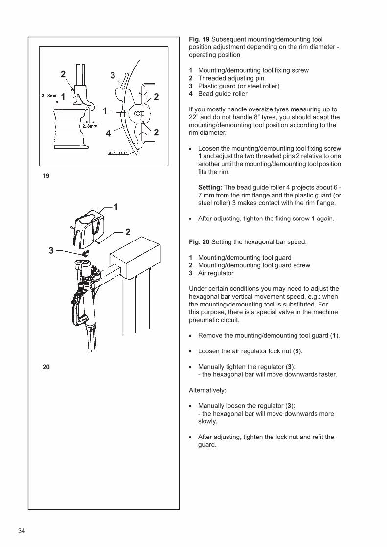
34
20
19
2
3
1
2 3
1
1 2
24
Fig. 19 Subsequent mounting/demounting tool position adjustment depending on the rim diameter - operating position
1 Mounting/demounting tool fi xing screw2 Threaded adjusting pin3 Plastic guard (or steel roller)4 Bead guide roller
If you mostly handle oversize tyres measuring up to 22” and do not handle 8” tyres, you should adapt the mounting/demounting tool position according to the rim diameter.
• Loosen the mounting/demounting tool fi xing screw1 and adjust the two threaded pins 2 relative to oneanother until the mounting/demounting tool positionfi ts the rim.
Setting: The bead guide roller 4 projects about 6 -7 mm from the rim fl ange and the plastic guard (orsteel roller) 3 makes contact with the rim fl ange.
• After adjusting, tighten the fi xing screw 1 again.
Fig. 20 Setting the hexagonal bar speed.
1 Mounting/demounting tool guard2 Mounting/demounting tool guard screw3 Air regulator
Under certain conditions you may need to adjust the hexagonal bar vertical movement speed, e.g.: when the mounting/demounting tool is substituted. For this purpose, there is a special valve in the machine pneumatic circuit.
• Remove the mounting/demounting tool guard (1).
• Loosen the air regulator lock nut (3).
• Manually tighten the regulator (3):- the hexagonal bar will move downwards faster.
Alternatively:
• Manually loosen the regulator (3):- the hexagonal bar will move downwards moreslowly.
• After adjusting, tighten the lock nut and refi t theguard.

35
Bild 19 Nachstellen der Montierkopfl age zum Felgendurchmesser– Arbeitsposition
1 Halteschraube des Montierkopfs2 Gewindestift für Verstellung3 Kunststoffschutz (oder Stahlanlaufrolle)4 Wulstführungsrolle
Bei vorwiegender Bearbeitung von großen Rädern bis 22” bzw. kleinen 8” Rädern ist es zweckmäßig, die Montierkopfstellung dem Felgendurchmesser anzupassen.
• Die Halteschraube 1 des Montierkopfes lösenund die beiden Gewindestifte 2 so gegeneinanderverstellen, dass die Lage des Montierkopfs derFelge entspricht.
Einstellung: Die Wulstführungsrolle 4steht ca. 6– 7 mm am Felgenhorn über, derKunststoffschutz (oder die Stahlanlaufrolle) 3 liegtam Felgenhorn an.
• Nach dem Einstellen die Halteschraube 1 wiederfestziehen.
Bild 20 Einstellen der Geschwindigkeit des Sechskants
1 Montierkopfabdeckung2 Schraube für Montierkopfabdeckung3 Luftregler
Unter bestimmten Umständen kann es nötig sein, die Geschwindigkeit der Vertikalbewegung des Sechskantes zu verstellen, z. B. wenn der Montierkopf ersetzt werden muss. Dazu ist im Pneumatikkreislauf der Maschine ein spezielles Ventil vorgesehen.
• Die Abdeckung des Montierkopfes (1)demontieren.
• Die Kontermutter des Luftreglers (3) lösen.
• Den Regler (3) manuell fester drehen:– der Sechskant bewegt sich schneller nachunten.
Alternativ:
• Den Regler (3) manuell lösen:– der Sechskant bewegt sich langsamer nachunten.
• Nach der Einstellung die Kontermutter wiederanziehen und die Abdeckung wieder montieren.
Fig. 19 Réglage de la tête de montage en fonction du diamètre de la jante - Position de travail
1 Vis de fi xation de la tête de montage2 Goupille fi letée pour le réglage3 Protection en plastique (ou butée en acier)4 Galet guide-talon
Si on opère principalement sur des roues de grandes jusqu’à 22», ou sur de petites roues de 8», il est recommandé de régler la tête de montage fonction du diamètre de la jante.
• Desserrer la vis de fi xation 1 de la tête de montageet régler les deux goupilles fi letées 2, une parrapport à l’autre, pour que la position de la têtecorrisponde à celle de la jante.
Réglage: Le galet guide-talon 4 dépasse d’environ 6-7 mm du bord de la jante et la proteciton en plastique (ou le rouleau en acier) 3 est au contact du bord de la jante.
• Après le réglage, resserrer la vis de fi xation 1.
Fig. 20 Réglage de la vitesse de la barre hexagonale.
1 Couvercle de la tête de montage2 Vis du couvercle de la tête de montage3 Régulateur d’air
Dans certaines conditions, il faut régler la vitesse du mouvement vertical de la barre hexagonale, par exemple quand la tête de montage doit être remplacée. Dans ce but, une valve spéciale est prévue dans le circuit pneumatique de la machine.
• Enlever le couvercle de la tête de montage (1).
• Desserrer le contre-écrou du régulateur d’air (3)
• Serrer le régulateur (3) à la main):- La barre hexagonale descendra plusrapidement.
Autre possibilités:
• Desserrer le régulateur (3) à la main:- La barre hexagonale descendra plus lentement.
• Le réglage terminé, serrer le contre-écrou etremettre en place le couvercle.

36
1
6. Tyre mounting and demountingbasics
• Use the plastic parts for clamping, a plasticmounting/demounting tool and special mountinglevers (coated or the like) to avoid damagingrims, in particular alloy rims, when mounting ordemounting tyres.
• Before demounting and/or mounting a tyre, applya suitable amount of commercial lubricant (liquidor paste) to the outside and inside of the beadand, for TD tyres, to the Denloc grooves. Neveruse other products which its is only assumedhave a lubricating action!
• Before demounting and/or mounting a tyre, checkthe rim for damage (deformation and/or damagedsurface of rim fl anges, rim lateral and radial run-out, corrosion, wear in general).
• With some tyre types, during mounting payattention to the sidewall rib and the direction ofmounting indicated on the tyre.
• When infl ating a tyre, increase the pressuregradually and if possible constantly monitoringthe bead. A seating pressure of 3.3 bar mustnot be exceeded. Make sure the tyre is correctlyseated relative to the rim. Do not exceed apressure of 3.5 bar (see also Chapter 9. Infl atinga tyre. Tyres which require a higher pressuremust be infl ated in suitable infl ating devices(safety cage and the like).
• Always fi t tyres on rims of correct size (identicalnominal diameter). For example, do not fi t tyreswith nominal size in mm on rims with nominalsize in inches and vice versa.
• For runfl at tyres always use the (1, Fig.15)pneumatic mounting tool, taking into account thespecifi c mounting and demounting instructionsprovided by the runfl at system manufacturer.
• Never fi t inner tubes in TD tyres.
• For instructions on RFT tyre changing (alsoapplicable to wide tyres), consult the separateinstructions, ref. no. EAZ0033G27A.
• Always pay attention to special mountingand demounting instructions provided by tyremanufacturers.

37
6. Grundsätzliche Hinweise zur Montageund Demontage eines Reifens
• Um bei den Arbeitsgängen die Felgen, besondersdie Leichtmetallfelgen, nicht zu beschädigen,sollten Kunststoffschutzteile zum Spannen,der Kunststoffmontagekopf und präparierteMontierhebel (Schutzüberzug, ummantelteAusführung oder Ähnliches) verwendet werden.
• Vor der Demontage bzw. Montage einesReifens die Wulstaußen- und -innenseiten, dieFelgenhörner und Felgenschultern, bei TD-Reifenauch die Denloc-Rille, mit einem geeignetenhandelsüblichen Gleitmittel (Fluid oderGleitpaste) ausreichend bestreichen. Keinesfallsandere, vermeintliche Gleitmittel verwenden.
• Vor jeder Demontage bzw. Montage einesReifens die Felge auf eventuelle Beschädigungen(Verformung und/oder Oberfl ächenbeschädigungder Felgenhörner, Höhen-und Seitenschlagder Felge, Korrosionsschäden, allgemeinerVerschleiß) kontrollieren.
• Bei einigen Reifentypen ist bei der Montage aufdie äußere Scheuerleiste oder auf die am Reifenangegebene Montagerichtung zu achten.
• Beim Füllen eines Reifens den Luftdruckmöglichst unter ständiger Beobachtung desWulsts stufenweise aufbauen. Ein Springdruckvon 3,3 bar sollte nicht überschritten werden.Auf den exakten Verlauf der Kennlinie desReifens zur Felge achten. 3,5 bar Setzdrucknicht überschreiten (siehe auch Punkt 9. Füllender Reifen). Reifen, die einen höheren Druckbenötigen, sind in geeigneten Fülleinrichtungen(Schutzkäfi g etc.) zu befüllen.
• Reifen immer nur auf Felgen der passendenGröße (gleiches Durchmesser-Nennmaß)montieren. Keine Reifen mit Nennmaß in mmauf Felgen mit Nennmaß in Zoll und umgekehrtmontieren.
• Räder mit Notlaufeigenschaften immer mitder pneumatischen Montagehilfe (1, Fig.15)montieren und dabei die herstellerspezifi schenMontage- und Demontageanleitungen beachten.
• TD-Reifen nur schlauchlos montieren,
• Hinweise für die Demontage und Montage vonRFT-Reifen (auch anwendbar bei Breitreifen)sind in der separaten Anleitung Best.-Nr.EAZ0033G27A aufgeführt.
• Spezielle Demontage- bzw. Montagehinweisedes Reifenherstellers beachten.
6. Règles fondamentales de démontageet de montage d’un pneu
• Pour ne pas endommager les jantes, surtout lesjantes en alliage, il est recommandé d’utiliser lespièces spéciales en matière plastique, une tête demontage en plastique et les leviers de montagespéciaux (rembourrés ou assimilés) au cours desdifférentes opérations.
• Avant le démontage et/ou le montage d’un pneu,appliquer une quantité suffisante de lubrifiantapproprié (liquide ou pâte) sur les côtés intérieuret extérieur de la jante (pneus TD) ainsi que dansla gorge Denloc des pneus TD. Ne jamais utiliserun produit lubrifi ant non spécifi que pour pneus!
• Avant le démontage et/ou le montage d’unpneu, contrôler si la jante présente des défauts(déformation et/ou surface endommagée desrebords de jante, voilage et faux-rond de la jante,corrosion, usure en général).
• Pour certains types de pneus, faire attention à lanervure latérale et au sens de montage indiqué surle pneu.
• Pendant le gonflage du pneu, augmenter lapression graduellement tout en observant le talonconstamment.On ne doit pas dépasser une pression de 3,3 bars.Veiller à ce que le fi let de centrage du pneu soitcentré exactement relatif au rebord de jante. Ne pasprogrammer la pression au-delà de 3,5 bars (voirégalement § 9. Gonfl age des pneus. Les pneus quidemandent une pression supérieure à 3,3 bar doiventêtre gonfl és dans un dispositif de gonfl age appropprié(par ex. cage de sécurité, etc.).
• Toujours chausser les pneus sur des jantes dontles dimensions sont appropriées (même diamètrenominal). Ne pas monter un pneu dont la mesurenominale est exprimée en mm sur une jante dontla mesure nominale est exprimée en pouces et viceversa.
• Pour les roues à roulage plat, utiliser toujours ledispositif pneumatique (1, Fig.15), en observant lesinstructions de montage et démontage spécifi quesdu fabricant de la roue à roulage plat.
• Ne jamais monter des chambres à air dans despneus TD.
• Pour les instructions de montage et démontage despneus RFT (également applicable pour les pneuslarges), voir l’instruction séparée, réf. EAZ0033G27A.
• Toujours faire attention aux instructions spécialesde montage et démontage du constructeur depneus.

38
A
B
21
22
23
2
1
7. Demounting a tyre
Always observe WdK or applicable national guidelines when demounting tyres.Demounting a tyre is much easier if, before demounting, a commercial lubricant is applied to the bead and the rim fl ange over which the bead will be demounted. Never use other products which it is only assumed have a lubricating action!
• Rotate or adjust the clamped wheel (1, Fig.22) sothat the wheel valve is approx. 10 cm in front of themounting/demounting tool (Fig. 21).
• Depress the pedal (2, Fig.22) to tilt the tower intothe operating position.
• Check the mounting/demounting tool setting and/or adjust it as described in Chapter 5. Adjustingthe mounting/demounting tool.
• Lift the upper bead over the mounting/demountingtool tip with the tyre lever (Fig. 21, arrow).
• To facilitate lifting, press the upper tyre beaddown on the opposite side to the mounting/demounting tool and push it into the rim dropbase (Fig. 23A, arrow).
• Depress pedal (1, Fig.22) to start turntable rotation.
• Leave the tyre lever on the mounting/demountingtool arm and press against the latter (Fig. 21,
arrow) until part of the tyre bead has gone overthe rim fl ange.
• Remove the tyre lever and rotate the turntablefurther.
• Continuing the demounting, make sure the part ofthe tyre bead opposite the mounting/demountingtool is in the drop base and avoid excessive beadtension (Fig. 23A, arrow).
• If the turntable stops as a result of excessive beadtension, turn the turntable backwards by liftingup the pedal and pressing the bead opposite themounting/demounting tool as far as possible intothe drop base, then continue demounting.
• In case of tyres with inner tubes, remove the tubebefore demounting the lower bead.
• To demount the lower tyre bead, push the part ofthe bead opposite the mounting/demounting toolinto the drop base and lift the tyre directly underthe mounting/demounting tool (Fig. 23B).
• Then proceed with demounting as described for theupper bead, with the bead always going correctlyover the beak-shaped tool (Fig. 23B, arrow).
• When the tyre has been demounted (2, Fig.22),depress the pedal to tilt the tower backwards.

39
7. Demontieren eines Reifens
Bei der Demontage von Reifen sind grundsätzlich die WdKLeitlinien (Wirtschaftsverband der deutschen Kautschukindustrie) zu beachten. Die Demontage eines Reifens wird wesentlich erleichtert, wenn vor dem Demontiervorgang die Wulstpartie und das Felgenhorn, über das montiert wird, mit einer handelsüblichen Montagepaste bestrichen werden. Keinesfalls andere, vermeintliche Gleitmittel verwenden!
• Das aufgespannte Rad so drehen (1, Bild 22) bzw.
stellen, dass das Radventil etwa 10 cm vor dem
Montierkopf steht (Bild 21).
• Das Schaltpedal niederdrücken (2, Bild 22). Die
Montiersäule kippt heran.
• Die Einstellung des Montierkopfes prüfen bzw.
wie unter Punkt 5. Einstellen des Montierkopfes
beschrieben einstellen.
• Den oberen Reifenwulst mit dem Montierhebel über
die Nase des Montierkopfs hebeln (Bild 21, Pfeil).
• Um das Aufhebeln zu erleichtern, auf der dem
Montierkopf gegenüberliegenden Radseite den
oberen Reifenwulst nach unten drücken und in das
Felgentiefbett hineinschieben (Bild 23A, Pfeil).
• Das Schaltpedal (1, Bild 22) niedertreten
(Arbeitsbewegung des Spanntellers).
• Den Montierhebel noch etwas auf dem Steg des
Montierkopfes halten und gleichzeitig gegen den
Montierkopf andrücken (Bild 21, Pfeil), bis ein Teil
des Reifenwulsts über das Felgenhorn gelaufen ist.
• Den Montierhebel wegnehmen und den Spannteller
weiterdrehen lassen.
• Während des weiteren Demontagevorgangs
darauf achten, dass der Reifenwulstteil gegenüber
dem Montierkopf im Tiefbett liegt und zu große
Wulstspannung vermieden wird (Bild 23A, Pfeil).
• Sollte der Spannteller infolge zu hoher Wulstspannung
stehen bleiben, den Spannteller durch Anheben des
Schaltpedals etwas zurückdrehen, den Reifenwulst
gegenüber dem Montierkopf so weit wie möglich
in das Tiefbett einschieben und die Demontage
fortsetzen.
• Bei Schlauchreifen den Schlauch vor der Demontage
des unteren Reifenwulsts herausnehmen.
• Zum Aufhebeln des unteren Reifenwulsts den
Wulstteil gegenüber dem Montierkopf in das Tiefbett
einschieben, und den Reifen direkt unter dem
Montierkopf anheben (Bild 23B).
• Nach dem Aufhebeln die Demontage in gleicher
Weise durchführen wie beim oberen Wulst.
Dabei muss der Wulst immer korrekt über den
Montierfi nger muss (Bild 23B, Pfeil).
• Nach der Demontage das Schaltpedal (2, Bild 22)niedertreten. Die Montiersäule kippt nach hinten.
7. Démontage des pneus
Observer strictement les règlements nationaux en vigueur pour le démontage des pneus.Le démontage d’un pneu est nettement facilité s’il est précédé de l’application d’un lubrifi ant approprié sur le talon et sur le bord de la jante d’où il sera démonté.Ne jamais utiliser un produit lubrifi ant non spécifi que pour pneus!
• Tourner ou régler la roue bloquée (1, Fig.22) demanière à ce que la roue se trouve à 10 cm environdevant la tête de montage (Fig. 21).
• Appuyer sur la pédale (2, Fig.22) pour incliner lemontant de machine en position de travail.
• Contrôler le réglage de la tête de montage, oula régler suivant le § 5. Réglage de la tête demontage.
• Passer le talon supérieur, par l’intermédiaire dulevier de montage, au-dessus du bec de la têtede montage (Fig. 21, fl èche).
• Pour faciliter cette opération, appuyer sur le talonsupérieur, opposé à la tête de montage, et le faireglisser dans la base de la jante (Fig. 23A, fl èche).
• Appuyer sur la pédale (1, Fig.22) pour mettre lemandrin en rotation.
• Laisser le levier de montage sur la traverse de latête de montage et le presser contre la tête (Fig.21, fl èche) jusqu’à ce qu’une partie du talon soitmontée sur le rebord de jante.
• Ensuite enlever le levier et continuer à fairetourner le andrin.
• En continuant le démontage, veiller à ce quele talon opposé à la tête de montage se trouvedans la base creuse de la jante et qu’une tensionextrême du talon soit empêchée (Fig. 23A, fl èche).
• Si le mandrin s’arrête par ce que le talon esttrop serré, faire tourner le mandrin en arrièreen soulevant la prédale et en pressant le talonopposé à la tête de montage dans la base creusede la jante. Puis continuer le démontage.
• S’il s’agit de pneus avec chambre à air, enlever lachambre à air avant le démontage du deuxièmetalon.
• Pour démonter le talon inférieur du pneu, presserle talon opposé à la tête de montage dans labase creuse et appliquer le levier directement au-dessous de la tête de montage (Fig. 23B).
• Continuer le démontage comme décrit pour letalon supérieur en veillant à ce que le talon passetoujours correctement au-dessus du bec demontage (Fig. 23B, fl èche).
• Après le démontage du pneu, appuyer sur lapédale (2, Fig.22) pour incliner le montant enarrière.

40
A
B
1
24
25
26
2
8. Montieren eines Reifens
Always observe WdK or applicable nationalguidelines when mounting tyres.Mounting a tyre is much easier if, before mounting, a commercial lubricant is applied to the bead and the rim fl ange over which the bead will be mounted. Never use other products which its is only assumed have a lubricating action!
• Clamp and/or adjust the rim so that the wheelvalve is approximately 180 degrees from themounting/demounting tool.
• Apply suffi cient lubricant to the tyre and rim.
• Place the tyre on the rim at an angle (Fig 24).
• Depress the pedal (2, Fig.25) to tilt the tower intothe operating position.
• Check the mounting/demounting tool setting and/or adjust as described in Chapter 5. Adjusting themounting/demounting tool.
• Position the tyre on the mounting/demounting toolso that the lower tyre bead runs from below themounting/demounting tool tip upwards over thebead guide support lip (Fig. 26A, arrow).
• Start mounting by depressing the pedal (1, Fig.
25). During mounting observe the correct bead run,otherwise stop and correct by hand, then proceeduntil the tyre bead has gone in completely over therim fl ange.
• In the case of tyres with inner tubes, insert thetube after mounting the lower tyre bead. To avoiddamage to the tube once fi tted, pay attention to thetube position as you continue with tyre mounting.
• To mount the upper tyre bead, position tyre againso that the bead runs from below the mounting/demounting tool tip upwards over the bead support lip(Fig. 26B, arrow).
• Start mounting the upper bead by depressingthe pedal (1, Fig. 25). After a part of the beadmeasuring approximately 10 - 15 cm has beenmounted over the rim fl ange, stop turntable

41
8. Montieren eines Reifens
Bei der Montage von Reifen sind grundsätzlich die WdKLeitlinien (Wirtschaftsverband der deutschen Kautschukindustrie) zu beachten.Die Montage eines Reifens wird wesentlich erleichtert, wenn vor dem Montiervorgang die Wulstpartie und das Felgenhorn, über das montiert wird, mit einer handelsüblichen Montagepaste bestrichen werden. Keinesfalls andere, vermeintliche Gleitmittel verwenden!
• Die Felge so aufspannen bzw. einstellen, dass
das Radventil etwa 180 Grad gegenüber dem
Montierkopf steht.
• Den Reifen und die Felge ausreichend mit
Montagepaste bestreichen.
• Den Reifen schräg auf die Felge legen (Bild 24).
• Das Schaltpedal (2, Bild 25) niederdrücken. Die
Montiersäule kippt heran.
• Die Einstellung des Montierkopfs prüfen bzw.
wie unter Punkt 5. Einstellen des Montierkopfs
beschrieben einstellen.
• Den Reifen jetzt so am Montierkopf positionieren,
dass der untere Reifenwulst von unterhalb der
Montiernase hoch über den Führungsbund der
Wulstführung verläuft (Bild 26A, Pfeil).
• Die Montage durch Niedertreten des
Schaltpedals (1, Bild 25) einleiten. Während des
Montagevorganges den korrekten Wulstverlauf
beobachten, wenn nötig den Vorgang stoppen,
den Wulstverlauf von Hand korrigieren und die
Montage fortsetzen, bis der Reifenwulst rundum
über das Felgenhorn eingelaufen ist.
• Bei Schlauchreifen den Schlauch nach der
Montage des unteren Reifenwulsts einlegen.
Damit der eingelegte Schlauch nicht beschädigt
wird, beim weiteren Montieren auf das Verhalten
des Schlauchs achten.
• Für die Montage des oberen Reifenwulsts den Reifen
ebenso positionieren, dass der Wulst von unterhalb
der Montiernase hoch über den Führungsbund der
Wulstführung verläuft (Bild 26B, Pfeil).
• Durch Niedertreten des Schaltpedals (1, Bild25) die Montage des oberen Wulsts einleiten.
Nachdem ein Teil des Wulsts von etwa 10–15 cm
über das Felgenhorn montiert ist, die
8. Montage des pneus
Observer strictement les règlements nationaux en
vigueur pour le montage des pneus.
Le montage d’un pneu est nettement facilité s’il est
précédé de l’application d’un lubrifi ant approprié sur le talon et sur le bord de la jante d’où il sera monté.Ne jamais utiliser un produit lubrifiant non spécifi que pour pneus!
• Serrer et/ou positionner la jante de sorte que lavalve de la roue se trouve environ à 180 degréspar rapport à la tête de montage.
• Appliquer une quantité suffi sante du lubrifi ant surle pneu et la jante.
• Puis poser le pneu en position inclinée sur lajante (Fig.24).
• Appuyer sur la pédale (2, Fig.25) pour incliner lemontant de machine en position de travail.
• Contrôler le réglage de la tête de montage, ou larégler comme décrit sous § 5. Réglage de la têtede montage.
• Positionner le pneu par rapport à la tête demontage de sorte que le talon inférieur monted’au-dessous du bec de montage au-dessus ducollet du galet guide-talon (Fig. 26A, fl èche).
• Commencer le montage par actionnement dela pédale (1, Fig. 25). Pendant le montage,observer le talon et interrompre le processus, sinécessaire, pour corriger la position du talon àla main. Ensuite continuer le montage jusqu’àce que le talon soit monté complètement sur lerebord de jante.
• S’il s’agit de pneus avec chambre à air, monter lachambre avant le deuxième talon. Faire attentionà la chambre à air au cours de la phase suivantepour ne pas l’abîmer.
• Pour le montage du talon supérieur, positionnerle pneu encore une foisde sorte que le talonmonte d’au-dessous du bec de montage au-dessus du collet du galet guide-talon (Fig. 26B,fl èche).
• Commencer le montage par actionnement dela pédale (1, Fig. 25). Une fois qu’une partie dupneu est montée d’environ 10 à 15 cm sur lerebord de jante, arrêter le mandrin, appuyer sur

42
27
rotation and press the mounted part of the bead downwards directly behind the mounting/demounting tool so that the bead is forced into the drop base of the rim and bead tension remains low (Fig. 27, arrow).
• Proceed with mounting until the tyre bead isounted completely.
• For subsequent tyre infl ation, loosen wheelclamping.
If the turntable speed slows excessively during assembly by abnormal bead friction, stop the procedure, turn the turntable back slightly, press the part of the bead already mounted down into the rim, if necessary using a bead pusher, then continue mounting. With easily mountable tyres and/or a skilled operator, mounting is possible without interruptions.One or two optionally available bead pushers (1, Fig. 27 and 14, Fig. 1) or the MH PRO pneumatic mounting tool (2, Fig. 27 and 15, Fig. 1) can be used to hold the tyre still during mounting.

43
Spanntellerbewegung stoppen, den montierten Wulstteil direkt hinter dem Montierkopf nach unten drücken, damit der Wulst ins Tiefbett der Felge gleitet und die Wulstspannung gering bleibt (Bild 27, Pfeil).
• Anschließend die Montage sinngemäß fortsetzen,bis der Reifenwulst rundum montiert ist.
• Zum anschließenden Füllen des Reifens dieRadspannung lösen.
Wenn der Drehteller Geschwindigkeit verlangsamt übermäßig bei der Montage durch anomale Wulst Reibung, den Vorgang stoppen, durch Anheben des Schaltpedals (1, Bild 21) den Spannteller etwas zurückdrehen, den schon montierten Reifenwulst nochmals kräftig nach unten in die Felge drücken, eventuell Wulstniederhalter einsetzen und die Montage fortsetzen. Bei leicht montierbaren Reifen bzw. geübter Bedienperson ist die Montage auch in einem Zug durchführbar. Für das Niederdrücken des Reifens während der Montage können ein oder zwei als Zubehör lieferbare Wulstniederhalter (1, Bild 27 sowie 14,Bild 1) oder die pneumatische Montagehilfe (2, Bild 27 sowie 15. Bild 1) verwendet werden.
la partie du pneu déjà montée et qui se trouve derrière la tête de montage, pour que le talon glisse dans la base creuse de la jante et limiter le serrage du talon (Fig. 27, fl èche).
• Continuer le montage jusqu’à ce que le talon soitmonté complètement.
• Pour le gonfl age du pneu, desserrer la roue.
Si la vitesse du plateau tournant ralentit excessivement lors du montage à cause du talon trop serré, arrêter la procédure, tourner légèrement en arrière le mandrin, presser le talon qui est déjà monté avec force vers le bas dans la jante, le cas échéant, utiliser un presse-talon, et poursuivre le montage. Pour immobiliser le pneu pendant le montage, Il est possible d’utiliser un ou deux presse-talons disponibles comme options (1, Fig. 27 et 14, Fig. 1) ou de l’outil de montage à actionnement pneumatique (2, Fig. 27 et 15, Fig. 1), qui sont disponibles en option.

44
9. Infl ating a tyre
For safety reasons, wear safety goggles and ear plugs when infl ating a tyre, particularly when using infl ating devices with air jets.When infl ating a tyre always follow WdK and applicable national guidelines and relevant safety standards to avoid most personal injuries and material damage.The infl ating pressure must not exceed the tyre operating pressure by more than 50% (recommended by WdK, German rubber industry economic association). Seating pressure should not exceed 3.3 bar. The fi nal pressure must not exceed 3.5 bar.
9.1 General information about tyre infl ating devices
For use in Germany, tyre infl ating devices (Fig. 28 / 31) are subject to German law with respect to calibration (Offi cial Journal - Measuring and calibration system law of 11 July 1969, paragraph one, No. 2, section 3).
Pressure gauge calibration lasts for two years after the end of the calendar year in which the equipment was last calibrated. For calibration in accordance with German regulations, the year until which the equipment is considered calibrated is specifi ed and/or for EC calibration, the date when the equipment was calibrated is stated.
The operator is responsible for any recalibration. When calibration has to be repeated, the equipment user must request calibration at the relevant offi ce.
For safety reasons a quick-infl ating valve preset to 3.5 bar is fi tted upstream of the pressure gauge for the pedal-operated infl ating device, guaranteeing that the maximum infl ating pressure does not exceed 3.5 bar. All valve switching operations during infl ation are clearly audible as a clicking noise, therefore this is not a malfunction.
If wheels require a higher pressure, they have to be infl ated using a special infl ation station equipped with safety devices such as a safety cage, retaining means and the like).

45
9. Füllen der Reifen
Aus Sicherheitsgründen ist beim Befüllen eines Reifens, besonders bei Verwendung von Füllanlagen mit Füllstoß, entsprechender Gehörschutz und eine Schutzbrille zu tragen.Beim Füllen eines Reifens mit Luft sind die WdK-Leitlinien sowie einige allgemeine Sicherheitskriterien zu beachten, damit eine Gefährdung für Personal und Arbeitsmittel weitgehend ausgeschlossen ist.Der Montagefülldruck darf den Betriebsdruck des Reifens nur bis zu 50 % überschreiten (Empfehlung des WdK – Wirtschaftsverband der Deutschen Kautschukindustrie).Der Springdruck soll 3,3 bar, der Setzdruck darf 3,5 bar nicht übersteigen.
9.1 Allgemeines zur Reifenfüllanlage
Die Reifenfüllanlagen (Bild 28 / 31) müssen bei Verwendung in der Bundesrepublik Deutschland geeicht sein und unterliegen der gesetzlich vorgeschriebenen Eichpfl icht (Bundesgesetzblatt – Gesetz über Mess- und Eichwesen vom 11. Juli1969, Erster Abschnitt § 2, Abs. 3).
Die Gültigkeit der Eichung für Luftdruckmessgeräte beträgt zwei Jahre und wird in Jahren nach Ablauf des Kalenderjahrs bemessen, in dem das Gerät zuletzt geeicht wurde. Bei Eichung nach deutscher Norm wird das Jahr angegeben, bis wann das Gerät geeicht ist, bzw. bei EG-Eichung, wann das Gerät geeicht wurde.
Für die jeweilige Nacheichung ist der Betreiber verantwortlich.Er wird hiermit aufgefordert, zum jeweiligen Zeitpunkt die Nacheichung beim zuständigen Eichamt zu beantragen.
Aus Sicherheitsgründen ist vor dem Manometer für die pedalbetätigte Füllanlage ein auf 3,5 bar eingestelltes Schnellbefüllventil eingebaut, das gewährleistet, dass der maximale Befülldruck nicht mehr als 3,5 bar beträgt. Die Schaltvorgänge sind als Klacken während des Füllvorgangs deutlich hörbar undstellen keine Fehlfunktion dar.
Müssen Räder mit höherem Setzdruck bearbeitet werden, ist zum Befüllen solcher Räder eine spezielle Füllstation zu verwenden, welche mit Sicherheitseinrichtungen (z. B. Sicherheitskäfi g, Festhaltevorrichtung usw.) versehen ist.
9. Gonfl age des pneus
Pour des raisons de sécurité, porter des lunettes de protection et des protège-oreilles pendant le gonfl age du pneu, notamment si on utiliser des systèmes de gonfl age à jet.Pour le gonfl age des pneus, observer toujours les règlements nationaux en vigueur et les normes de sécurité qui s’appliquent pour exclure tout dommage à des personnes ou tout dommage matériel.La pression de gonfl age ne doit pas dépasser la pression d’exercice du pneu de plus de 50 pour-cent (recommandé par l’Union des Industries de Caoutchouc Allemande).La pression de gonfl age ne doit pas dépasser 3,3 bar, la pression programmée ne doit pas dépasser 3,5 bars.
9.1 Généralités concernant le dispositif
de gonfl age Pour un emploi en Allemagne, les systèmes de gonfl age (Fig. 28 / 31) sont soumis à la législation allemande concernant l’étalonnage.Au cas où il serait nécessaire à l’étranger, l’étalonnage est à la charge et à la responsabilité du client.
Pour des raisons de sécurité, une soupape à gonfl age rapide préréglée à 3,5 bars est montée en amont du manomètre, pour le dispositif de gonfl age actionné par pédale pour assurer que la pression de gonfl age maximale ne dépasse pas 3,5 bars. Le passage d’un état à l’autre de la soupape pendant le gonfl age est clairement perceptible: il ne s’agit pas d’un défaut de fonctionnement.
S’il faut gonfl er des pneus sous une pression plus élevée, utiliser un poste de gonfl age spécial avec dispositifs de sécurité (comme par ex. une cage de sécurité, des moyens de retenue, etc.).

46
9.2 Beading the tiresBeading means the initial grip of the tire bead on the rim, in order to allow the infl ation operations and subsequent settling in the seat on the rim.
Safety Precautions:
WARNING: DO NOT USE THE TIRE CHANGER TO INFLATE TIRES.
COMPRESSED AIR DEVICES ON THE TIRE CHANGER ARE ONLY DESIGNED TO FACILITATE THE TUBELESS TIRE BEADING OPERATION.
NEVER EXCEED THE MAXIMUM PRESSURE ALLOWED BY THE TIRE MANUFACTURER.
THE OPERATOR MUST STAND SAFELY CLEAR FROM THE WHEEL WHEN BEADING THE TIRE, AND PRESSURE MUST BE MONITORED FREQUENTLY TO AVOID EXCESSIVE PRESSURE.
BEFORE BEADING, CHECK THE CONDITION OF TIRE AND RIM.
CHECK FOR CORRECT SEALING BETWEEN THE VALVE AND THE FITTING AT THE END OF THE AIR HOSE. AN AIR LEAK CAN GIVE INCORRECT PRESSURE READINGS AND CREATE SAFETY HAZARDS
CHECK THAT THE READING ON THE PRESSURE GAUGE IS “ZERO” WHEN IT IS NOT IN USE.
THE COMPLETE SEATING THE BEAD ON THE RIM IS A VERY DANGEROUS STAGE OF THE TIRE MOUNTING PROCEDURE.
TO COMPLETE THE BEADING OPERATION AND INFLATE THE TIRE CORRECTLY, PLACE IT IN AN APPROPRIATE TYPE APPROVED CAGE.
A TIRE BURST, WHATEVER ITS CAUSE, CAN RESULT IN SERIOUS INJURY OR DEATH.
AVOID MOUNTING TIRES THAT ARE 1/2” SMALLER IN DIAMETER THAN THE RIM, DOING SO FAILS TO ENSURE THAT THE BEADS ARE SEALED PROPERLY IN THEIR SEATS: THIS COULD BE A SOURCE OF DANGER WHEN DRIVING.

47
9.2 Eindrücken der ReifenwülsteUnter Wulsteindrücken wird verstanden, dass man die Reifenwülste anfänglich so an der Felge anlegt, dass das Rad danach gefüllt werden kann und sich die Wülste dadurch vollständig in ihre Sitzen an der Felge einfügen.
Vorsichtmaßnahmen:
ACHTUNG: VERWENDEN SIE DAS REIFENMONTIERGERÄT NICHT ALS FÜLLVORRICHTUNG.
VORRICHTUNGEN ZUM EINFÜLLEN VON DRUCKLUFT, DIE AM REIFENMONTIERGERÄT VORHANDEN SIND, HABEN NUR DEN ZWECK, DAS WULSTEINDRÜCKEN SCHLAUCHLOSER REIFEN BZW.
DER VOM HERSTELLER VORGEGEBENE REIFENDRUCK DARF IN KEINEM FALL ÜBERSCHRITTEN WERDEN.
BEIM EINDRÜCKEN DES WULSTES MUss DER BEDIENER dEN SICHERHEITSABSTAND EINHALTEN, UND DER DRUCK MUss häufi g KONTROLLIERT WERDEN, UM EINEN ÜBERDRUCK ZU VERMEIDEN.
VOR DEM WULSTEINDRÜCKEN EINES REIFENS SIND DER ZUSTAND DES REIFENS UND DER FELGE ZU ÜBERPRÜFEN.
SICHERSTELLEN, DASS DER ANSCHLUSSTUTZEN DES LUFTEINFÜLLSCHLAUCHS FEST AUF DEM VENTIL SITZT. DURCH EINEN LUFTVERLUST AN DIESER STELLE KANN DIE DRUCKANZEIGE VERFÄLSCHT WERDEN, WAS EINE GEFAHR DARSTELLT.
SICHERSTELLEN, DASS DER ZEIGER DES DRUCKMESSERS IM RUHEZUSTAND AUF ‚NULL’ STEHT.
DIE VÖLLIGE ANPASSUNG DES WULSTES IN DER FELGE IST EINE SEHR GEFÄHRLICHE PHASE BEI DER MONTAGE EINES REIFENS.
UM DAS EINDRÜCKEN DES WULSTES ABZUSCHLIESSEN UND DAS RAD ANGEMESSEN ZU FÜLLEN, LEGT MAN ES IN EINEN ZUGELASSENEN KÄFIG.
EIN AUS WELCHEN GRÜNDEN AUCH IMMER PLATZENDER REIFEN KANN SCHWERE ODER SOGAR TÖDLICHE VERLETZUNGEN VERURSACHEN.
ES IST ZU VERMEIDEN, REIFEN MIT EINEM DURCHMESSER EINZUSETZEN, DER UM 1/2” KLEINER IST ALS DIE FELGE. IN DIESEM FALL KANN DER RICHTIGE HALT DER WÜLSTE IN IHREM SITZ NICHT GEWÄHRLEISTET WERDEN, WAS IM ENDEFFEKT EINE GEFAHR BEIM FAHREN DARSTELLT.
9.2 Enjantage du talon des pneusPar enjantage du talon, on entend l’adhérence intiale du talon du pneu à la jante, de manière à permettre la suite des opérations à savoir le gonfl age et une parfaite pénétration du talon dans le logement de la jante.
Consignes de sécurité:
ATTENTION : NE PAS UTILISER LE DEMONTE-PNEUS COMME DISPOSITIF DE GONFLAGE.
LES DISPOSITIFS DE GONFLAGE A AIR COMPRIME, PRESENTS SUR LE DEMONTE-PNEUS ONT COMME BUT DE FACILITER L’ENJANTAGE DU TALON DU PNEU TUBELESS.
IL EST ABSOLUMENT INTERDIT DE DEPASSER LA PRESSION MAXIMALE ADMISSIBLE PAR LE FABRICANT DU PNEUMATIQUE.
L’OPERATEUR DOIT RESTER A UNE DISTANCE DE SECURITE QUAND IL PROCEDE L’ENJANTAGE DU TALON DU PNEU. LA PRESSION DOIT ETRE CONTROLEE FREQUEMMENT POUR EVITER UN GONFLAGE EXCESSIF.
AVANT D’ENJANTER LE TALON DU PNEU, CONTROLER L’ETAT DU CAOUTCHOUC ET DE LA JANTE.
S’ASSURER DE L’ETANCHEITE ENTRE LE RACCORD DE LA VALVE ET L’EXTREMITE DU TUBE D’AIR COMPRIME. UNE FUITE D’AIR PEUT DETERMINER UNE LECTURE ERRONEE DE LA PRESSION ET UNE SITUATION DE DANGER.
VERIFIER SI L’AIGUILLE DU MANOMETRE EST SUR ZERO, EN CONDITION DE REPOS.
LA PHASE AU COURS DE LAQUELLE LE TALON VIENT PRENDRE PARFAITEMENT SA PLACE DANS LE LOGEMENT DE LA JANTE EST UNE PHASE EXTREMEMENT DANGEREUSE DU MONTAGE D’UN PNEU.
POUR COMPLETER L’ENJANTAGE DU TALON ET GONFLER LA ROUE CORRECTEMENT, LA PLACER DANS UNE CABINE HOMOLOGUEE.
QUELLE QU’EN SOIT L’ORIGINE, L’EXPLOSION D’UN PNEU PEUT PROVOQUER DES BLESSURES GRAVES VOIRE MORTELLES.
MEME S’IL EST POSSIBLE D’INTRODUIRE DES PNEUS AYANT UN DIAMETRE DE ½” PLUS PETIT QUE LA JANTE, LA TENUE DES TALONS DANS LES LOGEMENTS DE LA JANTE DANS UN TEL CAS N’EST PAS GARANTIE ET PEUT REPRESENTER UN DANGER POUR LES OCCUPANTS DU VEHICULE.

48
34
1
1
2
30
29
28
Beading Tubeless: tires
Perform the beading with the wheel blocked on the tire changer.
• Ensure that both the beads and the inside of therim are thoroughly lubricated.
• Screw the valve insert.
• Connect the compressed air hose to the valve (1,Figure 28).
• Operate the compressed air to ensure the beadsare seated.
STOP THE COMPRESSED AIR AS SOON AS THE BEADS GRIP THE RIM WELL.
• Place the wheel in a type approved cage to fi nishinfl ating and completely settle the beads in their
seats on the rim.
Beading tubeless tires is sometimes diffi cult because the beads may be very close together (e.g. owing to incorrect stacking) and so fail to seal against the rim properly.In this event it may be helpful to place the wheel on the fl oor in a vertical position and ‘bounce’
it while introducing air with the pedal control or with
the nozzle (Figura 29).
Beading with the GT device:
The machine can be provided with a GT device,
necessary for bead seating of tubeless tires.
• Connect the compressed air hose to the valve
(1,Figure 28).
• Position the GT device beading nozzle between
tire and rim, pointing the air jet inside the tire
(2,Figure 28).
• Press the infl ation pedal (1, Fig. 30) and the
button (3, Fig. 30) on the Nozzle. The injectors
(4, Fig. 30) eject a large volume of air and the
tyre beads properly seal the rim fl anges allowing
the subsequent infl ation.
STOP THE COMPRESSED AIR AS SOON AS THE
BEADS GRIP THE RIM WELL.
• Place the wheel in a type approved cage to fi nishinfl ating and completely settle the beads in their
seats on the rim.
WARNING: WHEN OPERATING THE BEADING
DEVICE IT IS COMPULSORY TO WEAR EAR
DEFENDERS TO PROTECTAGAINST NOISE
AND SAFETY GOGGLES TO PREVENT ANY
CONTAMINATION BY DUST AND OTHER
IMPURITIES BLOWN BY THE AIR JET.

49
Wulsteindrücken bei schlauchlosen Reifen:
Beim Wulsteindrücken muss das Rad am Reifenmontiergerät aufgespannt sein.
• Sicherstellen, dass beide Wülste und dieInnenseite der Felge gründlich geschmiert sind.
• Den Ventilaufsatz anschrauben.
• Den Druckluftschlauch an das Ventil anschließen(1, Bild 28).
• Die Steuerung für die Druckluft betätigen, umzu gewährleisten, dass sich die Wülste guteinpassen.
DIE STEUERUNG STOPPEN, SOBALD DIE WÜLSTE GUT AN DER FELGE ANLIEGEN.
• Das Rad in einen zugelassenen Käfi g legen,um es fertig zu füllen und damit sich die Wülstevollständig an die Felge anlegen.
Das Wulsteindrücken erweist sich manchmal als schwierig, da die Wülste (z.B. aufgrund falscher Lagerung) zu stark gegeneinander gedrückt sind und deshalb die Anpassung an die Felge nicht einfach ist.In diesem Fall kann es hilfreich sein, das Rad auf den Boden zu legen und in die senkrecht Stellung springen zu lassen, während man mit dem Pedal oder mit der Pistole die Luft einlässt (Bild 29).
Wulsteindrücken mit der GT-Vorrichtung:
Die Maschine kann mit einer GT-Vorrichtung ausgestattet sein, die zur Wulstanpassung von schlauchlosen Reifen nötig ist.
• Den Druckluftschlauch an das Ventil anschließen(1, Bild 28).
• Die Wulsteindrückdüse der GT-Vorrichtungzwischen Reifen und Felge platzieren und denLuftstoß in den Reifen richten (2, Bild 28).
• Das Reifenfüllpedal (1, Bild 30) und den Knopfauf der GP Düse (3, Bild 30) ganz durchdrücken.Aus den Injektionsdüsen (4, Bild 30) strömteine große Luftmenge, und die Wulste werdengegen das Felgenhorn gepreßt, wodurch dasnachträgliche Reifenfüllen ermöglicht wird.
DIE STEUERUNG STOPPEN, SOBALD DIE WÜLSTE GUT AN DER FELGE ANLIEGEN.
• Das Rad in einen zugelassenen Käfi g legen,um es fertig zu füllen und damit sich die Wülsteendgültig in die Felge einfügen.
WARNUNG: WÄHREND DER BETÄTIGUNG DER WULSTEINDRÜCKVORRICHTUNG IST ES FÜR DEN BEDIENER PFLICHT, EINEN GEHÖRSCHUTZ UND EINE SCHUTZBRILLE ZU TRAGEN, DAMIT VOM LUFTSTRAHL AUFGEWIRBELTER STAUB NICHT DIE AUGEN ERREICHEN KANN.
Enjantage talon de pneus Tubeless:
Effectuer l’enjantage talon avec la roue bloquée sur le démonte-pneus.
• S’assurer que les deux talons et l’intérieur de lajante sont bien lubrifi és.
• Visser l’insert valve.
• Raccorder le tube de l’air comprimé à la valve (1,Figure 28).
• Actionner la commande de l’air comprimé pourgarantir que les talons pénètrent bien dans leurlogement.
ARRETER LA COMMANDE DES QUE LES TALONS ADHERENT PARFAITEMENT A LA JANTE.
• Placer la roue dans une cage homologuée pourterminer le gonfl age et faire en sorte que les talonspénètrent bien dans leur logement sur la jante.
Il arrive parfois que les pneus tubeless soient diffi ciles à enjanter, les talons ayant été forcés au cours du stockage, ce qui ne facilite pas la tenue sur la jante.Dans ce cas, il peut être utile de poser la roue sur le sol et de la faire sauter en position verticale au moment où on envoie avec la pédale ou le pistolet de l’air comprimé (Figura 29).
Enjantage talon avec dispositif GT:
La machine peut être équipée d’un dispositif GT, nécessaire pour le montage des pneus tubeless sur jante.
• Raccorder le tube de l’air comprimé à la valve(1,Figure 28).
• Placer la buse d’enjantage talon du dispositifGT entre le pneu et la jante, en orientant le jet àl’intérieur du pneu (2,Figure 28).
• Appuyer à fond sur la pédale de gonfl age (1,Fig. 30) et le bouton du Bec Gicleur (3, Fig.30). Une grande quantité d’air est expulsée parles injecteurs (4, Fig. 30) et les talons adhèrentau bord de la jante en permettant le successifgonfl age.
ARRETER LA COMMANDE DES QUE LES TALONS ADHERENT PARFAITEMENT A LA JANTE.
• Placer la roue dans une cage homologuée pourprocéder au gonfl age et faire en sorte que le talon pénètre bien dans son logement sur la jante.
ATTENTION : QUAND LE DISPOSITIF D’ENJANTAGE TALON EST EN MARCHE, LE PORT D’EQUIPEMENTS DE PROTECTION DES YEUX ET DES OREILLES EST OBLIGATOIRE, LE JET D’AIR POUVANT PROJETER IMPURETES ET POUSSIERES.

50
31
2
1
3
4
56
78
10. MaintenanceBefore maintenance work is carried out, disconnect the machine from the supply lines and make sure that it cannot be switched on again accidentally.The Health and Safety at Work (UVV) regulations applicable must be observed for maintenance work.
Basically, the tyre changer requires no particular maintenance.The reduction unit is for-life lubricated and so does not require maintenance.Maintenance work which must be carried out at regular intervals to ensure proper and fault-free operation is listed below:• Clean the machine daily. Remove dirt from the
clamping jaw guides and lubricate the guides. • Check the oil level in lubricator every 2 or 3 days.
The oil level in the lubricator (Fig. 31) must never drop below the suction pipe.Only oil with a viscosity of 2.5 °- 7° (16 - 55 cST) at 50°C must be used for topping up (for oils allowed see label on machine). After topping up, always adjust the lubricator as follows.
• Check oil dosage: After operating the pedals (6and 8, Fig. 31) 2 - 3 times, one drop of oil should fall into the sight glass. If necessary adjust using the dosing screw (1, Fig. 31).
• Regularly drain the condensation from the fi ltercollector (3, Fig. 31). To do so, turn the locking ring (4, Fig. 31) anti-clockwise.
• Once a month, disconnect the machine from thecompressed air network (2, Fig. 31) and clean the fi lter condensation collector (3, Fig. 31).
• At least once a year clean the worst of the dirtfrom the bearings, guides and the like and keep them running smoothly.
• At least once a year lubricate with a commerciallubricant.
• Whenever necessary, clean the lubricator leveltube only with water, petroleum or spirit (not petrol for use in cars!).
10.1 TroubleshootingBefore any repair work is carried out, disconnect the machine from the supply lines and make sure that it cannot be switched on again accidentally.During repair work, the Health and Safety at Work (UVV) regulations applicable must be observed.
If faults occur which cannot be eliminated by the operator, call the after-sales service.
10.2 After-sales service, spare partsWhen ordering spare parts, remember to indicate the serial number shown on the data plate.
After-sales service:
The company website provides information about the Customer Assistance service around the world:
http://www.snapon-equipment.euHotline (International) +49 8634 622-8996
Hotline (German): +49 8634 622-8994Reception +49 8634 622-0
· Snap-on Equipment Germany ·· Konrad-Zuse-Straße,1 D-84579 Unterneukirchen

51
10. Wartung
Bei Wartungsarbeiten ist die Maschine von den Versorgungsnetzen zu trennen und gegen unbeabsichtigtes Einschalten zu sichern.Generell sind bei Wartungsarbeiten die diesbezüglichen Unfallverhütungsvorschriften (UVV) zu beachten.
Die Reifenmontiermaschine bedarf keiner besonderen Wartung.Das Getriebe ist mit einer Dauerschmierstoffüllung versehen und wartungsfrei.Nachfolgend sind die Wartungsarbeiten aufgeführt, die regelmäßig durchgeführt werden müssen, um den ordnungsgemäßen Betrieb und eine störungsfreie und zuverlässige zu gewährleisten:• Maschine täglich reinigen. Dabei Schmutz aus
den Gleitbahnen der Spannklauen entfernen undGleitbahnen schmieren.
• Alle 2 bis 3 Tage Ölstand im Nebelöler prüfen.Der Nebelöler (Bild 31) muss stets bis über dasSaugrohr mit Öl gefüllt sein. Zum Nachfüllen nurein Öl mit einer Viskosität von 2,5° – 7° (16–55cST) bei 50 °C verwenden (zulässige Öle sieheMaschinenaufkleber). Nach dem Nachfüllen ist derNebelöler stets wie folgt einzustellen.
• Öldosierung prüfen. Nach 2 – 3 Schaltvorgängenmit den Pedalen (Bild 31, Pos. 6 und 8) muss einTropfen Öl in die Schaukuppel fallen, gegebenenfallsüber die Dosierschraube (Bild 31, Pos. 1) einstellen.
• Kondensat im Auffangbehälter des Filters (Bild 31,Pos. 3) regelmäßig ablassen. Hierzu die Nutmutter(Bild 31, Pos. 4) gegen den Uhrzeigersinn drehen.
• Monatlich die Maschine vom Druckluftnetz trennen(Bild 31, Pos. 2) und den Kondensat-Auffangbehälterdes Filters (Bild 31, Pos. 3) reinigen.
• Mindestens einmal jährlich Lagerstellen, Gleit- undFührungsbahnen von übermäßig angefallenemSchmutz säubern und gängig halten.
• Mindestens einmal jährlich mit einem handelsüblichenSchmierfett schmieren: Gelenkbolzen, Lagerstellen,Gleitbahnen sowie die Spanneinrichtung.
• Das Schauglas des Nebelölers bei Bedarf nur mitWasser, Petroleum oder Reinigungsbenzin (kein Kfz-Kraftstoff) reinigen.
10.1 StörungenBei Reparaturarbeiten ist die Maschine von den Versorgungsnetzen zu trennen und gegen unbeabsichtigtes Einschalten zu sichern.Generell sind bei Reparaturarbeiten die diesbezüglichen Unfallverhütungsvorschriften (UVV) zu beachten.
Sollten Störungen auftreten, welche vom Betreiber nicht zu beheben sind, den Kundendienst anfordern.
10.2 Kundendienst, ErsatzteileBei Bestellung von Ersatzteilen immer die Maschinennummer (Typenschild) angeben.Kundendienst in der Bundesrepublik :Auf der Internet-Seite sind Informationen über den Kundendienst in den verschiedenen Ländern verfügbar:
http://www.snapon-equipment.euHotline (International) +49 8634 622-8996
Hotline (German): +49 8634 622-8994Reception +49 8634 622-0
· Snap-on Equipment Germany ·· Konrad-Zuse-Straße,1 D-84579 Unterneukirchen
10. Entretien
Avant l’entretien, débrancher la machine de toutes les lignes d’alimentation en énergie et la verrouiller pour éviter une mise en marche accidentelle.En général, pour les travaux d’entretien, respecter la réglementation en matière de prévention des accidents du travail.
En principe, le démonte-pneus n’a pas besoin d’un entretien particulier.Les engrenages sont graissés à vie et ne requièrent aucun type d’entretien.Voici la liste des travaux d’entretien qui doivent être effectués régulièrement pour assurer un fonctionnement impeccable:• Nettoyer la machine chaque jour. Nettoyer les glissières
des mors de serrage et lubrifi er les glissières.• Vérifi er le niveau d’huile dans le lubrifi cateur tous les
2 ou 3 jours. Le lubrifi cateur (Fig. 31) doit toujoursêtre rempli d’huile au-delà du tube d’aspiration.Pour l’appoint, n’utiliser qu’une huile d’uneviscosité de 2,5° - 7° E (16 - 55 cST) à 50 °C(pour les huiles préconisées, voir l’étiquetteadhésive sur la machine). Après l’appoint,toujours régler le lubrifi cateur comme suit.
• Vérifi er le dosage de l’huile. Après avoir actionnéles pédales (6 et 8, Fig. 31) deux à trois coups, unegotte d’huile doit tomber dans le verre indicateur;sinon, régler la vis de dosage (1, Fig. 31).
• Purger périodiquement le collecteur decondensat du fi ltre (3, Fig. 31) en tournant labague (4, Fig. 31) dans le sens inverse desaiguilles d’une montre.
• Chaque mois, débrancher la machine du réseaupneumatique (2, Fig. 31) et nettoyer le collecteurde condensat du fi ltre (3, Fig. 31).
• Au moins une fois par an, débarrasser lescoussinets, les glissières etc. des incrustationspour améliorer le roulement.
• Au moins une fois par an, lubrifi er avec unegraisse en vente dans le commerce.
• Nettoyer le tube de niveau du lubrificateur, le cas échéant.Avec de l’eau, du pétrole ou de l’essence détergente (nejamais utiliser de l’essence pour voitures!).
10.1 DéfautsAvant une réparation, débrancher la machine de toutes les lignes d’alimentation en énergie et la verrouiller pour éviter une mise en marche accidentelle. En général, pour les réparations, respecter la réglementation en matière de prévention des accidents du travail.
Si la panne ne peut être réparée par l’opérateur, faire appel au service d’assistance.
10.2 Service après vente, pièces détachées
Dans une commande de pièces détachées, toujours préciser le numéro de série indiqué sur la plaque signalétique. Service après vente:Le site Internet fournit des informations concernant le service après-vente dans les différents pays:
http://www.snapon-equipment.euHotline (International) +49 8634 622-8996
Hotline (German): +49 8634 622-8994Reception +49 8634 622-0
· Snap-on Equipment Germany ·· Konrad-Zuse-Straße,1 D-84579 Unterneukirchen

52
10” - 24”12” - 24”15” - 23”
1”-17”/40-440 mm3 - 14”
230VAC, 1Ph, 50-60Hz, 16A240VAC, 1Ph, 50-60Hz, 16A200VAC, 1Ph, 50-60Hz, 20A
1000 Nm0,9 kW
7/18
7” - 13”17.5””
1000 mm
8–12 bar
12060 N250–330 l70 dB (A)
88,7 dB (A)
1700 mm1350 mm1950 mm
230 kg
WHITE MINERAL OIL 15ONDINA OIL 15ENERGOL WT3LOBELIA SB 15
MARCOL 82
11. Technical specifi cations
(Basic version)External clamping rangeInternal clamping rangewith motorcycle jawsBead breaking range:Rim width
- Std Electrical connections -
(Standard)(USA)(Japan) Torque
Motor power
Turntable speed (rpm)
- Wheels specifi cation -
with special jaws for trolley and mini wheelswith special jaws for light-truck wheels Max. wheel diameter
Compressed air supplyBead breaker force at 10 bar pressureand 200 mm arm openingAir consumption per wheel, approx. Sound levelSound level when infl ating with air jet system
- Machine dimensions -
Max. depth (including space for tower tilting) Max. widthMax. heightApprox. weight
- Appropriate oil for oiler -
TAMOIL:SHELL :BP :TOTAL :ESSO :

53
10” - 24”12” - 24”15” - 23”
1”-17” (40-440 mm)3 - 14”
230VAC, 1Ph, 50-60Hz, 16A240VAC, 1Ph, 50-60Hz, 16A200VAC, 1Ph, 50-60Hz, 20A
1000 Nm0,9 kW
7/18
7” - 13”17.5””
1000 mm
8–12 bar
12060 N250–330 l70 dB (A)
88,7 dB (A)
1700 mm1350 mm1950 mm
230 kg
WHITE MINERAL OIL 15ONDINA OIL 15ENERGOL WT3LOBELIA SB 15
MARCOL 82
10” - 24”12” - 24”15” - 23”
1”-17”/40-440 mm3 - 14”
230VAC, 1Ph, 50-60Hz, 16A240VAC, 1Ph, 50-60Hz, 16A200VAC, 1Ph, 50-60Hz, 20A
1000 Nm0,9 kW
7/18
7” - 13”17.5””
1000 mm
8–12 bar
12060 N250–330 l70 dB (A)
88,7 dB (A)
1700 mm1350 mm1950 mm
230 kg
WHITE MINERAL OIL 15ONDINA OIL 15ENERGOL WT3LOBELIA SB 15
MARCOL 82
11. Technische Daten
(Basisversion)AußenspannungsbereichInnenspannungsbereichmit MotorradspannklauenAbdrückbereichFelgenbreite
- Elektroanschluss -(Standard)(USA)(Japan) AntriebsmomentMotorleistungArbeitsgeschwindigkeit des Spanntellers (U/m)
- Räder-Spezifi kation -mit Sonderspannklauen für Karren-und Kleinrädermit Sonderspannklauen für LLkw-Räder Maximaler Raddurchmesser
LuftanschlussAbdrückkraft bei 10 bar Pressdruckund 200 mm ArmöffnungLuftbedarf pro Rad, etwaGeräuschemissionGeräuschemission bei Befüllung mit Luftfüllstoß
- Maschinenabmessungen -Tiefe max. (mit Platz zum Kippen der Säule) Breite max. Höhe max. Gewicht ca.
- Für den Filter/Luftöler empfohlene Öle -TAMOIL:SHELL :BP :TOTAL :ESSO :
11. Données techniques
(Version base)Gamme de serrage de l’extérieurGamme de serrage de l’intérieuravec mors pour roues de motoGamme de décollage:Largeur jantes
- Alimentation électrique -(Standard)(USA)(Japan) Couple d’entraînementPuissance du moteurVitesse de service du mandrin (t/min)
- Spécifi cation Roues -avec mors pour roues mini et de chariotsavec mors spéciaux pour camionnettes Diamètre roue maxi
Air compriméPression du décolleur à 10 barset ouverture du bras de 200 mmConsommation d’air par roue, env. Niveau sonoreNiveau sonore pendant le gonfl age avecun système de gonfl age à jet d’air
- Dimensions de la machine -Profondeur maxi - (y compris l’espace pour l’inclinaison du montant) Largeur maxiHauteur maxiPoids environ
- Huiles conseillées pour fi ltre/ huileur -TAMOIL:SHELL :BP :TOTAL :ESSO :

54
12. Disposing of the unit
When you decide to get rid of your unit, contact your reseller for a quote or for the regulations on disposal which apply to the unit.
12.1 Instructions for disposalFor waste electrical and electronic equipment
At the time of disposal, at the end of the lifetime of this equipment, you must:
1. NOT dispose of the equipment as municipal wasteand separate collection is mandatory.
2. Ask the retailer about collection points authorisedfor regular disposal.
3. Stick to the standards for correct waste management,to prevent potential effects on the environment andhuman health.
This symbol indicates that separate collection of waste electrical and electronic equipment is mandatory for scrapping.

55
12. Entsorgung
Wenn das Gerät entsorgt werden soll, setzen Sie sich bitte mit Ihrem Händler in Verbindung und fragen Sie ihn nach einem Preisangebot bzw. nach den Bestimmungen zur Entsorgung des Geräts.
12.1 Anleitung zur EntsorgungFür elektrische und elektronische Geräte
Für die Entsorgung des Geräts am Ende seiner Lebensdauer gelten folgende Vorschriften:
1. Das Gerät darf NICHT als Hausmüll entsorgtwerden, sondern muss dem Sondermüll zugeführtwerden.
2. Informieren Sie sich bei Ihrem Händler über dieMüllsammelzentren, die zur ordnungsgemäßenEntsorgung befugt sind.
3. Befolgen Sie die Richtlinien für dieordnungsgemäße Behandlung von Müll, ummögliche Gefahren für die Umwelt und für dieGesundheit zu vermeiden.
Dieses Symbol zeigt an, dass es Pfl icht ist, elektrische und elektronische Geräte nach der Verschrottung dem Sondermüll zuzuführen.
12. Vente
Lorsque vous décidez de vendre la machine, contactez votre revendeur pour obtenir le prix offert ou les règlements appropriés pour la revente de la machine.
12.1 Consignes de démolitionInstructions d’equipements electriques et electroniques
Au moment de la mise à la décharge, à la fi n de la vie de cet équipement, il est obligatoire de :
1. NE PAS ELIMINER cet appareillage commedéchet urbain mais d’effectuer le tri sélectif de sescomposants.
2. S’informer auprès du revendeur sur les centresde collecte autorisés au tri et au traitement de cetype de déchet.
3. Respecter les normes sur la gestion des déchetspour éviter tout risque probable de nuisances àl’environnement et à la santé des personnes.
Ce symbole indique l’obligation d’effectuer le tri sélectif des appareils électriques et électroniques au moment de sa mise à la décharge.

Manufacturing Facility
Snap-on Equipment S.r.L.
Via Provinciale per Carpi 33,
42015 Correggio (R.E.), Italy
Tel.: ++39 (0)522 733480
Fax: ++39 (0)522 733479
Tech
nic
al m
odifi
catio
ns
rese
rved.
copyright 2016
GB
FR
DE
SO
E D
igital C
ode: O
M_
SU
N S
TC
5545_
16-0
5_
EN
-FR
-DE
_A
_Z
EE
WH
119A
03
Notice: The information contained in this document is subject to change without notice. SUN makes no war-
ranty with regard to present documentation. SUN shall not be liable for errors contained herein or for in-
cidental consequential damages in connection with furnishings, performance, or use of this material.