Tap changer
42
A tap changer is a device fitted to power transformers for regulation of the output voltage to required levels. This is normally achieved by changing the ratios of the transformers on the system by altering the number of turns in one winding of the appropriate transformer/s. Tap changers offer variable control to keep the supply voltage within the limits. The 2 ½% step can be used on transformers with
-
Upload
vivek1292 -
Category
Engineering
-
view
475 -
download
6
Transcript of Tap changer

A tap changer is a device fitted
to power transformers for
regulation of the output voltage
to required levels. This is
normally achieved by changing
the ratios of the transformers
on the system by altering the
number of turns in one winding
of the appropriate
transformer/s. Tap changers
offer variable control to keep
the supply voltage within the
limits. The 2 ½% step can be
used on transformers with

Voltage regulation is normally achieved by changing
the ratios of the transformers on the system by altering
the number of turns in one winding of the appropriate
transformer/s. Tap changers offer variable control to
keep the supply voltage within these limits. Tap
changers can be on load or off load. On load tap
changers generally consist of a diverter switch and a
selector switch operating as a unit to effect transfer
current from one voltage tap to the next. Tap changers
can be adjusted to fit the application needs.

To supply a desired voltage to the load.
To counter the voltage drops due to loads.
To counter the input supply voltage changes on load.
Additionally required to perform the task of regulation of
active and reactive power flows.

Some form of impedance is present to
prevent short circuiting of the tapped
section.
A duplicate circuit is provided so that
the
load current can be carried by one circuit
whilst switching is being carried out on the
other.

Nominal Voltage set point.
Bandwidth (the amount of variation allowed before a
tap change
occurs).
Time delay (The amount of time the voltage must be
outside the
bandwidth before a tap change occurs) .
Line drop compensation ( a way vary the set point
voltage to
compensate for heavy loads)

Tap point is placed In star connected winding, near the star point.
In delta connected winding, at the center of the winding.
In autotransformer, between the series and common windings

Tap changers connected to the primary or
secondary side windings of the transformer
depending on:
Current rating of the transformer.
Insulation levels present.
Type of winding within the transformer (eg. Star, delta or
autotransformer).
Position of tap changer in the winding.
Losses associated with different tap changer configurations eg.
Coarse tap or
reverse winding.
Step voltage and circulating currents.
Cost.
Physical size.

No-Load Tap Changer (NLTC or
DETC)
On Load Tap Changer (OLTC
Mechanical tap changers
Thyristor-assisted tap changers
Solid state (thyristor) tap
changers

No-Load Tap Changer (NLTC or
DETC)In low power, low voltage transformers, the tap point can
take the form of a connection terminal, requiring a power lead to
be disconnected by hand and connected to the new terminal.
Since the different tap points are at different voltages, the two
connections can not be made simultaneously, as this would
short-circuit a number of turns in the winding and produce
excessive circulating current.Mechanical tap
changersA mechanical tap changer
physically makes the new
connection before releasing the
old using multiple tap selector
switches, but avoids creating
high circulating currents by
using a diverter switch to
temporarily place a large

Solid state (thyristor) tap changer
Recently developed which uses thyristors both to
switch the load current and to pass the load current in the
steady state. Their disadvantage is that all of the non-
conducting thyristors connected to the unselected taps still
dissipate power due to their leakage current.
Thyristor-assisted tap changers
Thyristor-assisted tap changers use thyristors to
take the on-load current while the main contacts change
over from one tap to the previous. This prevents arcing on
the main contacts and can lead to a longer service life.

On Load Tap Changer (OLTC)
OLTCs enable voltage regulation and/or phase shifting by
varying the transformer ratio under load without interruption. On
load tap changers generally consist of a diverter switch and a
selector switch operating as a unit to effect transfer current from
one voltage tap to the next. The selector selects the taps and is
operating in the transformer oil. The diverter is the actual switch
with high current contacts that balances the load from one tap to
the other. The divertor is inside a separate compartment inside the
transformer tank. The diverter and selector are positionned above
each-other and driven by the same axe. The voltage between the
taps is known as the step voltage, which normally lies between
0.8 % and 2.5 % of the rated voltage of the transformer.Two switching principles have been used for load
transfer
operation :
1.the high-speed resistor-type OLTCs
2.the reactor-type OLTCs.
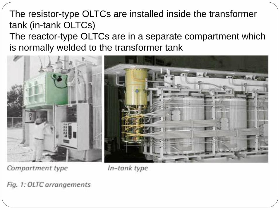
The resistor-type OLTCs are installed inside the transformer
tank (in-tank OLTCs)
The reactor-type OLTCs are in a separate compartment which
is normally welded to the transformer tank


The OLTC changes the ratio of a transformer by adding or
subtracting to and turns from either the primary or the secondary
winding.

The “make before break contact concept”, is used. The transition
impedance in the form of a resistor or reactor consists of one or
more units that bridge adjacent taps for the purpose of transferring
load from one tap to the other without interruption or appreciable
change in the load current. At the same time they limit the
circulating current (IC ) for the period when both taps are used.

Examples of commonly used winding
schemesIn star/wye connection, windings have
regulation applied to the neutral end.

Regulation of delta-connected windings requires a three-
phase OLTC whose three phases are insulated according
to the highest system voltage applied.
Today, the design limit for three-phase OLTCs with phase-
to-phase insulation is the highest voltage for equipment of
145 kV.
To reduce the phase-to-phase stresses on the delta-
OLTC the three pole mid-winding arrangement (fig. 7 c)
can be used.

For regulated autotransformers, the most appropriate
scheme is chosen with
regard to regulating range, system conditions and/or
requirements, as well as weight and size restrictions during
transportation. Autotransformers are always wye-connected.

The switching capacity itself is primarily a function of the
contact design, contact speed and arc-quenching agent.
Based on that OLTC are of two type:
1. Oil-type OLTCs
2. Vacuum-type OLTCs
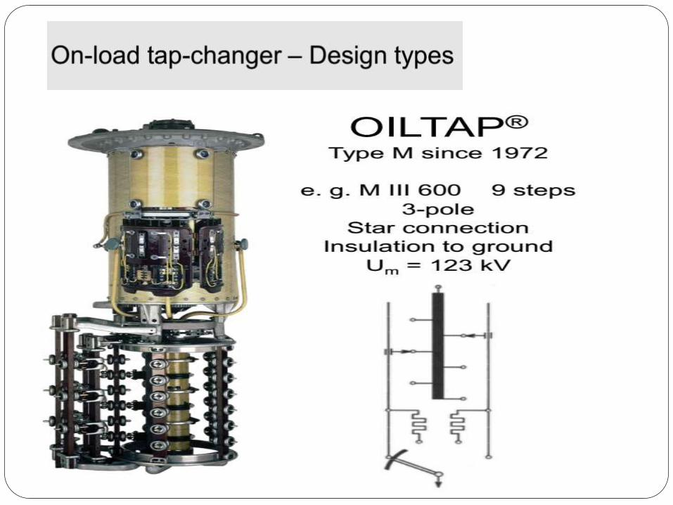
Resistor oil-type OLTCs
In an oil-type OLTC, the OLTC is immersed in
transformer oil and switching contacts make and break
current under oil.
For higher ratings and higher voltages comprises a
diverter switch (arcing switch) and a tap selector.
For lower ratings, OLTC designs in which the functions of
the diverter switch (arcing switch) and the tap selector are
combined in a selector switch (arcing tap switch) are used.

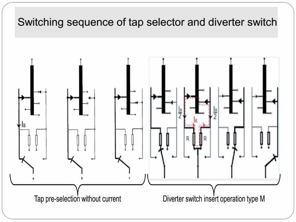
1. With a diverter switch & a tap selector operation takes place in two steps :
a. The next is preselected by the tap selector at no load.
b. The diverter switch then transfers the load current from the tap in
operation to the preselected tap.
The OLTC is operated by means of a drive mechanism.
Switching time of a divertor switch is b/w 40 &60 ms.
Transition resistor are inserted which are loaded for 20-30 ms.
Total operation time 3-1o sec.
2. A selector switch(arcing tap switch) carries out the tap in one step from the
tap in service to the adjacent tap


Reactor oil-type OLTCsThe following types of switching are used for reactor oil-
type OLTCs:
1. Selector switch (arcing tap switch)
2. Diverter switch (arcing switch) with tap selector


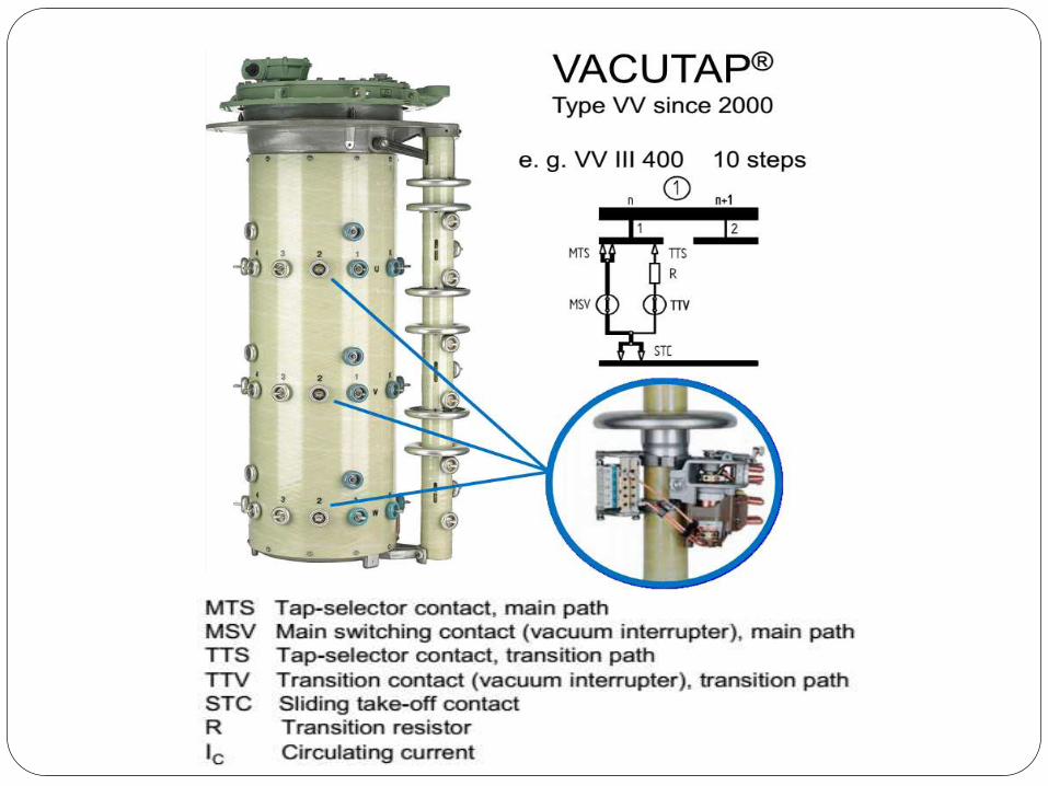
Technical features The vacuum interrupter is a hermetically-sealed system.
There is no interaction with the surrounding medium, despite the arc.
The switching characteristics do not depend on the surrounding medium.
Low energy consumption.
Reduced contact wear.
Elimination of the insulating medium as the arc quenching agent.
Elimination of by-products e. g. carbon when using transformer oil.
On-line filter is unnecessary.
Easy disposal.
No aging of the quenching medium.
Constant or even improving switching characteristics throughout the entire
lifespan of the
vacuum interrupters (getter effect).
No interaction/oxidation during switching.
High rate of recondensation of metal vapour on contacts extends contact
life.
Constantly low contact resistance.
Extraordinary fast dielectric recovery of up to 10 kV/µs.
Ensures short arcing times (maximum one halfcycle) even in the case of
large phase angles


To select the appropriate OLTC, the following key data
of the corresponding transformer windings should be
known:
MVA rating.
Connection of tap winding (for wye, delta or singlephase
connection).
Rated voltage and regulating range.
Number of service tap positions.
Insulation level to ground.
Lightning impulse and power frequency voltage of internal
insulation.
The following OLTC operating data may be derived
from this information:
Rated through-current: Iu
Rated step voltage: Ui

The appropriate tap-changer can be
determined:
OLTC type
Number of poles
Nominal voltage level of OLTC
Tap selector size/insulation level
Basic connection diagram

During the operation of the diverter switch (arcing switch)
from the end of the tap winding to the end of the coarse
winding and vice versa, all turns of the whole tap winding and
coarse winding are inserted in the circuit.
This results in a leakage impedance value which is
substantially higher than during operation within the tap
winding where only negligible leakage impedance of one step
is relevant. The higher impedance value in series with the
transition resistors has an effect on the circulating current
which is flowing in the opposite direction through coarse
winding and tap winding during diverter switch operation.
Consequently a phase shift between switched current and
recovery voltage takes place at the transition contacts of the
diverter switch and may result in an extended arcing time.
In order to ensure optimal selection, it is necessary to
specify the leakage impedance of coarse winding and tap


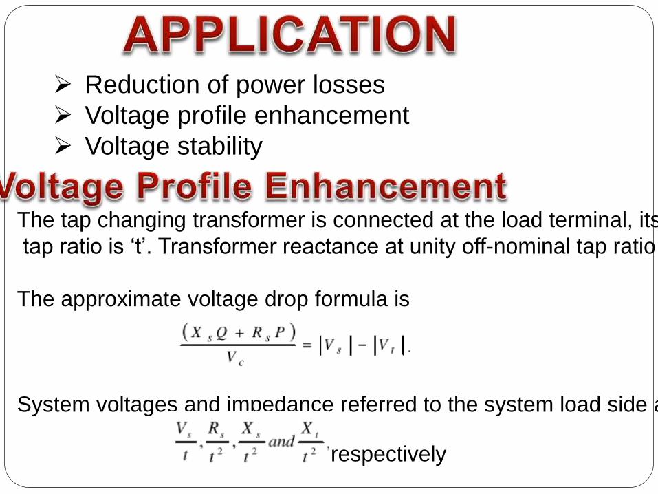
Reduction of power losses
Voltage profile enhancement
Voltage stability
The tap changing transformer is connected at the load terminal, its off
tap ratio is ‘t’. Transformer reactance at unity off-nominal tap ratio is X.
The approximate voltage drop formula is
System voltages and impedance referred to the system load side are
respectively


Voltage value of sec. terminal of transformer can be
regulated using tap changer. This regulation also affects
the calculation of the thevenin equivalent parameters.
Changes of equivalent parameters cause a change of
voltage stability conditions.

In the radial distribution system, each radial feeder is
divided into load sections with a tap changing transformer at
the beginning of the distribution network. However, there is the
need to find the tap setting of the substation transformer that
would give minimum distribution loss while satisfying the
operating constraints under a certain load pattern. These
operating constraints are voltage drop, current capacity and
radial operating structure of the system. The mathematical
formulation for the minimization of power loss tap changer
problems is


![11KV TAP CHANGER TYPE [A] ABS - On Load Gears LOAD GEARS 11KV TAP CHANGER TYPE [A] ABS TECHNICAL DETAILS [A]ABS11 OLTC is air insulated, externally mounted On Load Tap Changer. This](https://static.fdocuments.in/doc/165x107/5aaeb09e7f8b9adb688ca6f2/11kv-tap-changer-type-a-abs-on-load-load-gears-11kv-tap-changer-type-a-abs.jpg)