Pneumatic - lowenberg.rs Catalogue-UK… · ADEX Valves Compact body with large flow Providing...
20
Catalogue PD0C00005GB01-ev Directional Control Valves M3 - M5 - G1/8 Pneumatic
Transcript of Pneumatic - lowenberg.rs Catalogue-UK… · ADEX Valves Compact body with large flow Providing...

Catalogue PD0C00005GB01-ev
Directional Control ValvesM3 - M5 - G1/8
Pneumatic
ADEX Valves
Summary Page
Introduction 4-5Adex valves overview 6-7
A00 Series characteristics 8A00 Series order codes 9-10
A05/A12 Series characteristics 11A05R/A12R Series valve order codes 12A05R/A12R Series manifold order codes 13A05P/A12P Series valve order codes 14A05P/A12P Series manifold order codes 15A05/A12 Series accessories order codes 16
A00 valves dimensions 17A05R/A12R in-line valve dimensions 18A05R/A12R manifold dimensions 19A05P/A12P subbases valve dimensions 20A05P/A12P manifold dimensions 21

ADEX Valves
Compact body with large flowProviding flexibility for your application plus saving spaceand costs saving in maintenance and installation.This series is ideal for driving cylinders of Ø10 toØ100 in diameter.
Quick response time,faster than 10ms(A05 series, Single solenoid)Uniquely designed pilot valve with fast response timeand low power consumption.
Tested life time more than50,000,000 times(Based on Parker laboratory test conditions)ADEX valves feature the well-reputed WCS (WearCompensation System) in the main spool, resulting in lowsliding friction and long service life.
Low power consumption only 0,6W(With indicator light and surge suppressor)Direct drive from PLC is possible, contributing to costreduction as well as down sizing of the DC power supply.
Multipin connector versionConnection by sub-D 25 on subbase.
Inline or subbases mounted (sideported) versions
Valves
A00SeriesA05SeriesA12Series
A05 5/2 and 5/3 versions
Body width
10 mm
A12 5/2 and 5/3 versions
Body width
15 mm
A00 3/2 NO and 3/2 NC versions
Body width
10 mm

ADEX Valves
Outputs ports selectable
Series Standard
Tapped hole
A00 M3 - M5
A05 M5
A12 G1/8
Manual overrideScrewdriver-operated manual override is standard.
Multipurpose tag availableFor the convenience of installation, testing, maintenance atag can be fixed to the top side of solenoid valve body.
Captured exhaust from main valveand pilot valve(Subbase mounting type)Exhaust air from pilot valve is captured together withexhaust air from main valve.Unlike conventional exhaust systems, exhaust air frompilot valve is not directly discharged to outside.This helps prevent air contamination in the atmosphere.
Tag

Internal Pilot Supply
Single Solenoid 3/2
Single Solenoid 5/2
Double Solenoid 5/2
Closed Center 5/3
Vented Center 5/3
Pressurised Center 5/3
Indicator LED & Surge Suppressor
Manual Override
Inline Mounting
IEM Manifold Mounting
Subbase Mounting
Electrical Collective Wiring
Port Sizes
M3
M5
G1/8
4mm Push-in Connector
6mm Push-in Connector
Ø6
Ø10
Ø16
Ø20
Ø25
Ø32
Ø40
Ø50
Ø63
Ø80
Ø100
ADEX Valves
Direct Operated Solenoid Inline IEM Valves
Series A00 A05R
Diameter of controlled cylinderPressure : 5 barLoad factor : 0.5Cylinder speed m/s 0,15 0,30 0,45 0,60 0,75Tube lenght : 1mTube diameter : A05 : 6 x 4 mm
A12 : 8 x 6 mm
M3 - M5 M5

A12R A05P A12P
ADEX Valves
Subbase Mounted Valves

A00 Series 3/2 Poppet Seal M3
• 0,6W low power solenoid
• NO or NC versions
• Ultra fast response time
• Suitable for vacuum operation
• Impulse or turn to lock manual override
Working pressure : NC : 0 to 7,1 bar or vacuum to 6,1bar*
: NO : 0 to 5,1 bar or vacuum to 4,2bar*
Working temperature : -5OC to 50OCStorage temperature : -40OC + 70OCFluid : air or gas 50µm filtered lubricated
or notResponse time : DC on 5ms off 5msExpected mechanical lifewith dry air at 6 bar 20OC 1 Hz: 50 million cycles
NOTE : All data applies for intermittent duty, for continuous duty : please consult Technical Dept'.
Operating information
Orientation : any planeMaximum operatingfrequency : cycles/min: 600 (10Hz)Degree of protection : IP40
Operating voltage : 12 and 24 V DC-10% to +10% intermittent dutyand -10% to 0% continuous duty
Surge suppression : Diode for DC versionConsumption : 0,55 W (without LED)
0,6W (with LED indicator light)Wiring : Connector 2,54mm pin spacingCv : 0,01
Additional information
* For vacuum operation: with normally open version; air supply is inverted i.e.
P - Vacuum, R - Pressured air
with normally closed version P - Pressured air, R - Vacuum
Normally closed valves (A005C23•P) cannot be mounted together with normally open valves (A005 23•P) on the same manifold
C23 : NC 1 : DC 24V P - Orientation top with LED and suppressorO23 : NO 2 : DC 12V
Manifold type No. of stations Type of solenoid Output port A, size
MMFS 8 A00 M3
Solenoid Function V oltage Connector
A00S C23 1 P
References
from 2 up to 16 A00 series M3 or M5 ports (20 on request)
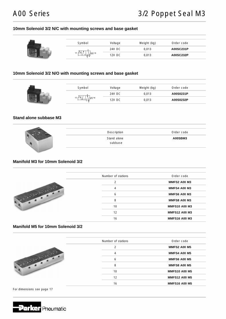
A00 Series 3/2 Poppet Seal M3
10mm Solenoid 3/2 N/C with mounting screws and base gasket
10mm Solenoid 3/2 N/O with mounting screws and base gasket
Stand alone subbase M3
Manifold M3 for 10mm Solenoid 3/2
Symbol Voltage Weight (kg) Order code
24V DC 0,013 A00SC231P
12V DC 0,013 A00SC232P
Symbol Voltage Weight (kg) Order code
24V DC 0,013 A00S0231P
12V DC 0,013 A00S0232P
Description Order code
Stand alone A00SBM3
Number of stations Order code
2 MMFS2 A00 M3
4 MMFS4 A00 M3
6 MMFS6 A00 M3
8 MMFS8 A00 M3
10 MMFS10 A00 M3
12 MMFS12 A00 M3
16 MMFS16 A00 M3
For dimensions see page 17
Manifold M5 for 10mm Solenoid 3/2
Number of stations Order code
2 MMFS2 A00 M5
4 MMFS4 A00 M5
6 MMFS6 A00 M5
8 MMFS8 A00 M5
10 MMFS10 A00 M5
12 MMFS12 A00 M5
16 MMFS16 A00 M5
subbase

A00 Series Mounting and Wiring Accessories
Description Order code
Connector with lead wire A05PDCCL5black (-), red (+), length 500mm
Connector with lead wire A05PDCCL10black (-), red (+), length 1000mm
Base gasket (pack of 10) A00SG
Pack of screws (pack of 20) A00SS
Blanking plate kit A00SBP
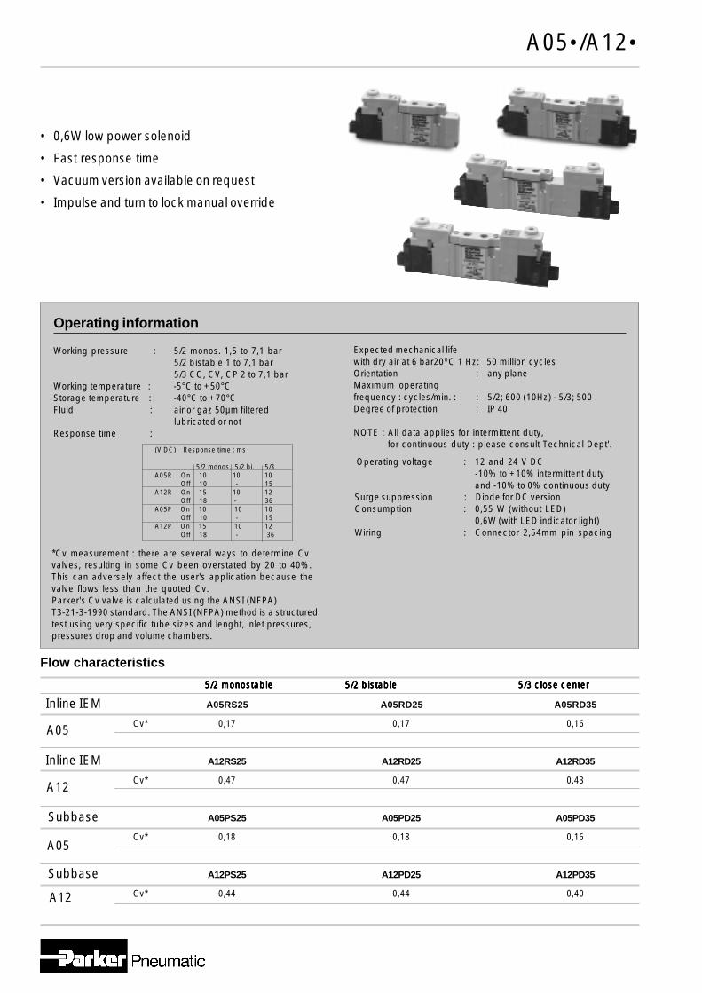
A05•/A12•
• 0,6W low power solenoid
• Fast response time
• Vacuum version available on request
• Impulse and turn to lock manual override
Operating information
Operating voltage : 12 and 24 V DC-10% to +10% intermittent dutyand -10% to 0% continuous duty
Surge suppression : Diode for DC versionConsumption : 0,55 W (without LED)
0,6W (with LED indicator light)Wiring : Connector 2,54mm pin spacing
Flow characteristics
Inline IEM A05RS25 A05RD25 A05RD35
Cv* 0,17 0,17 0,16
Inline IEM A12RS25 A12RD25 A12RD35
Cv* 0,47 0,47 0,43
Subbase A05PS25 A05PD25 A05PD35
Cv* 0,18 0,18 0,16
Subbase A12PS25 A12PD25 A12PD35
Cv* 0,44 0,44 0,40
A05
A12
A12
A05
5/2 monostable 5/2 monostable 5/2 monostable 5/2 monostable 5/2 monostable 5/2 bistable 5/2 bistable 5/2 bistable 5/2 bistable 5/2 bistable 5/3 close center 5/3 close center 5/3 close center 5/3 close center 5/3 close center
Expected mechanical lifewith dry air at 6 bar20OC 1 Hz: 50 million cyclesOrientation : any planeMaximum operatingfrequency : cycles/min. : : 5/2; 600 (10Hz) - 5/3; 500Degree of protection : IP 40
NOTE : All data applies for intermittent duty, for continuous duty : please consult Technical Dept'.
(V DC) Response time : ms
5/2 monos. 5/2 bi. 5/3A05R On 10 10 10
Off 10 - 15A12R On 15 10 12
Off 18 - 36A05P On 10 10 10
Off 10 - 15A12P On 15 10 12
Off 18 - 36
*Cv measurement : there are several ways to determine Cvvalves, resulting in some Cv been overstated by 20 to 40%.This can adversely affect the user's application because thevalve flows less than the quoted Cv.Parker's Cv valve is calculated using the ANSI (NFPA)T3-21-3-1990 standard. The ANSI (NFPA) method is a structuredtest using very specific tube sizes and lenght, inlet pressures,pressures drop and volume chambers.
Working pressure : 5/2 monos. 1,5 to 7,1 bar5/2 bistable 1 to 7,1 bar5/3 CC, CV, CP 2 to 7,1 bar
Working temperature : -5°C to +50°CStorage temperature : -40°C to +70°CFluid : air or gaz 50µm filtered
lubricated or notResponse time :

Main data for directional control valves A05R and A12R series
For dimensions see page 18
A05R/A12R Series Inline / IEM mounting type
Electrically actuated 5/2 single solenoid
Symbol Threaded Voltage Order codeconnection
M5 24V DC A05RS251PM5MF
G1/8 24V DC A12RS251PG1MF
Electrically actuated 5/2 double solenoid
Symbol Threaded Voltage Order codeconnection
M5 24V DC A05RD251PM5MF
G1/8 24V DC A12RD251PG1MF
Electrically actuated 5/3 closed center
Symbol Threaded Voltage Order codeconnection
M5 24V DC A05RD351PM5MF
G1/8 24V DC A12RD351PG1MF
Electrically actuated 5/3 vented center
Symbol Threaded Voltage Order codeconnection
M5 24V DC A05RE351PM5MF
G1/8 24V DC A12RE351PG1MF
Electrically actuated 5/3 pressurised center
Symbol Threaded Voltage Order codeconnection
M5 24V DC A05R0351PM5MF
G1/8 24V DC A12R0351PG1MF
Gasket and screwsfor IEM mountingsupplied with eachvalve
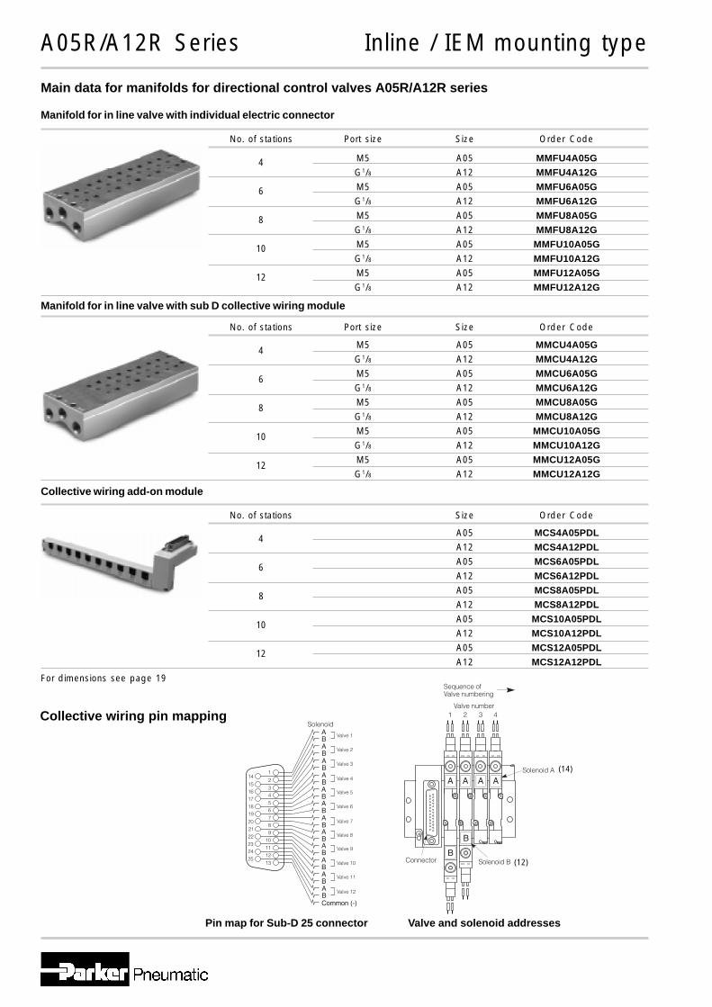
Main data for manifolds for directional control valves A05R/A12R series
For dimensions see page 19
A05R/A12R Series Inline / IEM mounting type
Manifold for in line valve with individual electric connector
No. of stations Port size Size Order Code
M5 A05 MMFU4A05G
G1/8 A12 MMFU4A12G
M5 A05 MMFU6A05G
G1/8 A12 MMFU6A12G
M5 A05 MMFU8A05G
G1/8 A12 MMFU8A12G
M5 A05 MMFU10A05G
G1/8 A12 MMFU10A12G
M5 A05 MMFU12A05G
G1/8 A12 MMFU12A12G
4
6
8
10
12
Manifold for in line valve with sub D collective wiring module
No. of stations Port size Size Order Code
M5 A05 MMCU4A05G
G1/8 A12 MMCU4A12G
M5 A05 MMCU6A05G
G1/8 A12 MMCU6A12G
M5 A05 MMCU8A05G
G1/8 A12 MMCU8A12G
M5 A05 MMCU10A05G
G1/8 A12 MMCU10A12G
M5 A05 MMCU12A05G
G1/8 A12 MMCU12A12G
4
6
8
10
12
Collective wiring add-on module
No. of stations Size Order Code
A05 MCS4A05PDL
A12 MCS4A12PDL
A05 MCS6A05PDL
A12 MCS6A12PDL
A05 MCS8A05PDL
A12 MCS8A12PDL
A05 MCS10A05PDL
A12 MCS10A12PDL
A05 MCS12A05PDL
A12 MCS12A12PDL
4
6
8
10
12
Collective wiring pin mapping
Pin map for Sub-D 25 connector Valve and solenoid addresses
(14)
(12)
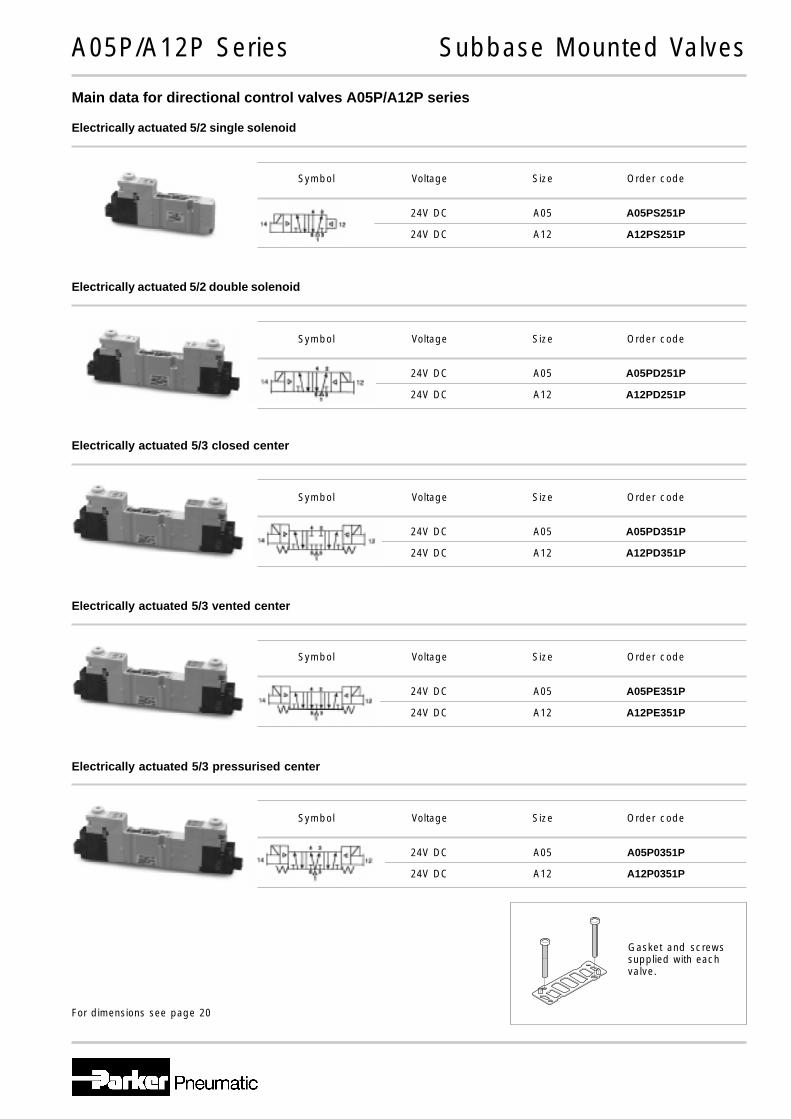
Main data for directional control valves A05P/A12P series
For dimensions see page 20
A05P/A12P Series Subbase Mounted Valves
Electrically actuated 5/2 single solenoid
Symbol Voltage Size Order code
24V DC A05 A05PS251P
24V DC A12 A12PS251P
Electrically actuated 5/2 double solenoid
Electrically actuated 5/3 closed center
Electrically actuated 5/3 vented center
Electrically actuated 5/3 pressurised center
Gasket and screwssupplied with eachvalve.
Symbol Voltage Size Order code
24V DC A05 A05PD251P
24V DC A12 A12PD251P
Symbol Voltage Size Order code
24V DC A05 A05PD351P
24V DC A12 A12PD351P
Symbol Voltage Size Order code
24V DC A05 A05PE351P
24V DC A12 A12PE351P
Symbol Voltage Size Order code
24V DC A05 A05P0351P
24V DC A12 A12P0351P
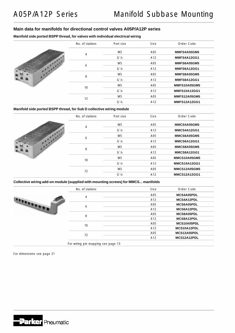
M5 A05 MMFS4A05GM5
G1/8 A12 MMFS4A12GG1
M5 A05 MMFS6A05GM5
G1/8 A12 MMFS6A12GG1
M5 A05 MMFS8A05GM5
G1/8 A12 MMFS8A12GG1
M5 A05 MMFS10A05GM5
G1/8 A12 MMFS10A12GG1
M5 A05 MMFS12A05GM5
G1/8 A12 MMFS12A12GG1
Main data for manifolds for directional control valves A05P/A12P series
A05P/A12P Series Manifold Subbase Mounting
Manifold side ported BSPP thread, for valves with individual electrical wiring
No. of stations Port size Size Order Code
4
6
8
10
12
M5 A05 MMCS4A05GM5
G1/8 A12 MMCS4A12GG1
M5 A05 MMCS6A05GM5
G1/8 A12 MMCS6A12GG1
M5 A05 MMCS8A05GM5
G1/8 A12 MMCS8A12GG1
M5 A05 MMCS10A05GM5
G1/8 A12 MMCS10A12GG1
M5 A05 MMCS12A05GM5
G1/8 A12 MMCS12A12GG1
Manifold side ported BSPP thread, for Sub D collective wiring module
No. of stations Port size Size Order Code
4
6
8
10
12
Collective wiring add-on module (supplied with mounting screws) for MMCS... manifolds
For dimensions see page 21
For wiring pin mapping see page 13
No. of stations Size Order Code
A05 MCS4A05PDL
A12 MCS4A12PDL
A05 MCS6A05PDL
A12 MCS6A12PDL
A05 MCS8A05PDL
A12 MCS8A12PDL
A05 MCS10A05PDL
A12 MCS10A12PDL
A05 MCS12A05PDL
A12 MCS12A12PDL
4
6
8
10
12

A05•/A12• Series Mounting and Wiring Accessories
Description Order code
Connector with lead wire A05PDCCL5black (-), red (+), length 500mm
Connector with lead wire A05PDCCL10black (-), red (+), length 1000mm
Mounting bracket A05R (1 bracket with 2 screws) A05RBS
Mounting bracket A12R (1 bracket with 2 screws) A12RBS
Identification tag for subbase valves A05PN(pack of 10)
IEM gasket (pack of 10) A05RGfor A05R/A12R A12RG
IEM mounting screws (pack of 20) A05RSfor A05R/A12R A12RS
Collective wiring connector A05PSCCMSingle solenoid PNP A12PSCCM
Collective wiring connector A05PDCCMDouble solenoid PNP A12PDCCM
Subbase gasket (pack of 10) A05PGfor A05P/A12P A12PG
Subbase mounting screws (pack of 20) A05PSfor A05P/A12P A12PS
IEM blanking plate kit (pack of 5) A05RGBPA12RGBP
Subbase blanking plate kit (pack of 5) A05PGBPA12PGBP

A00 Series Dimensions
A00 - Subbase
A B C D E25,4 10,5 0,4 4,4 20
F G H J K3 7 39,2 5 28,2
L M N P Q8,2 4,5 12 2,5 10
R S T15 2,7 9,7
Dimensions in mm
A00 - Manifold
A B C D E9,2 25,4 8 2,5 13
F G H J K8 10 41,5 5 30,5
L M N P Q5 8,5 0,6 10,5 12
Dimensions in mm
n = number of stations
A00 - Subbase
A00 - Manifold
6,5+10,5n
11,5+10,5n
M3 or M5threaded ports
M5 threaded2 portsboth ends
S (2 mtg. holes)
S (2 mtg. holes)
Manualoverride
M3 threaded3 ports
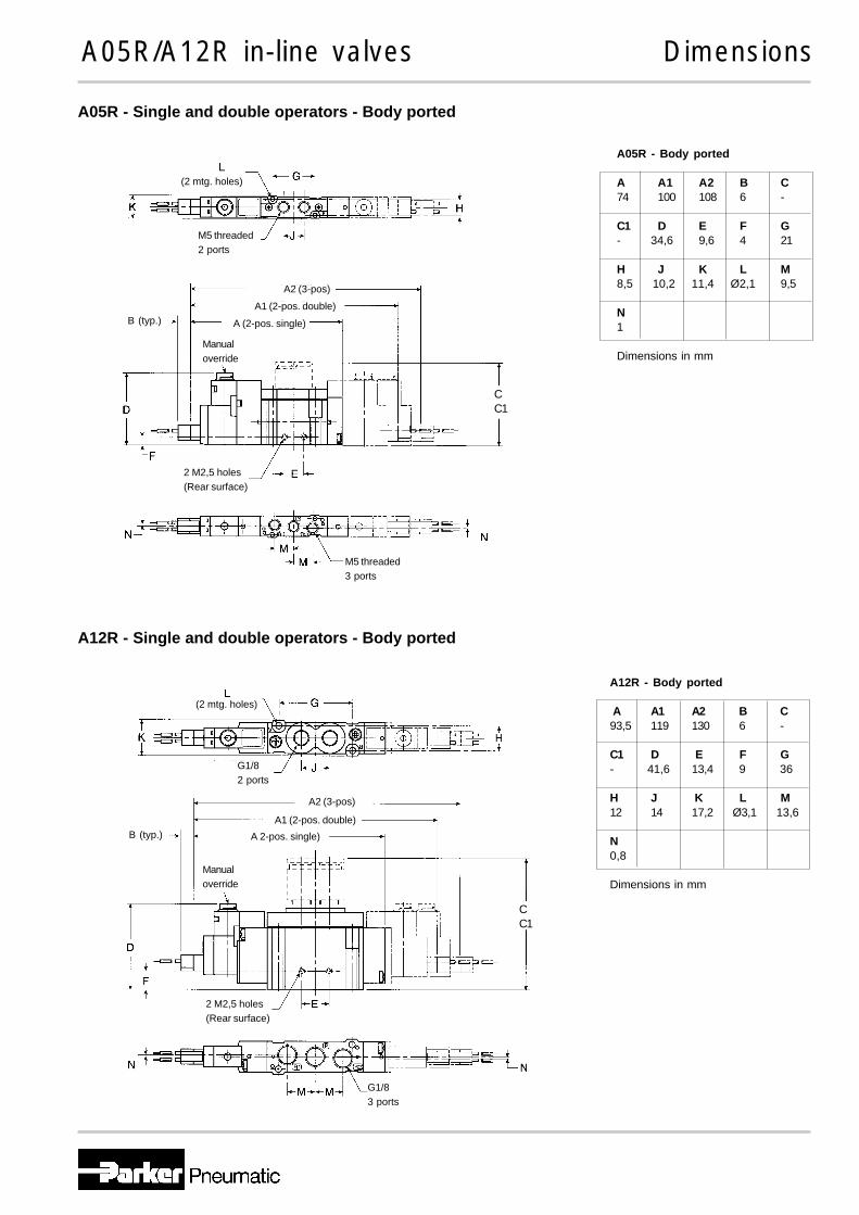
A05R/A12R in-line valves Dimensions
A12R - Body ported
A A1 A2 B C93,5 119 130 6 -
C1 D E F G- 41,6 13,4 9 36
H J K L M12 14 17,2 Ø3,1 13,6
N0,8
Dimensions in mm
A05R - Single and double operators - Body ported
A12R - Single and double operators - Body ported
A05R - Body ported
A A1 A2 B C74 100 108 6 -
C1 D E F G- 34,6 9,6 4 21
H J K L M8,5 10,2 11,4 Ø2,1 9,5
N1
Dimensions in mm
CC1
CC1
(2 mtg. holes)
M5 threaded2 ports
A2 (3-pos)
A1 (2-pos. double)
A (2-pos. single)B (typ.)
Manualoverride
M5 threaded3 ports
2 M2,5 holes(Rear surface)
(2 mtg. holes)
G1/82 ports
A2 (3-pos)
A1 (2-pos. double)
A 2-pos. single)B (typ.)
Manualoverride
G1/83 ports
2 M2,5 holes(Rear surface)
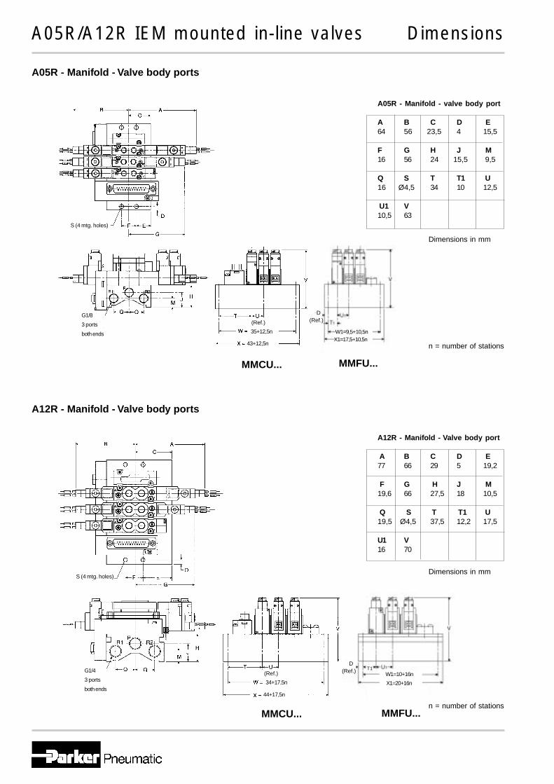
A05R/A12R IEM mounted in-line valves Dimensions
A05R - Manifold - valve body port
A B C D E64 56 23,5 4 15,5
F G H J M16 56 24 15,5 9,5
Q S T T1 U16 Ø4,5 34 10 12,5
U1 V10,5 63
A12R - Manifold - Valve body port
A B C D E77 66 29 5 19,2
F G H J M19,6 66 27,5 18 10,5
Q S T T1 U19,5 Ø4,5 37,5 12,2 17,5
U1 V16 70
A05R - Manifold - Valve body ports
A12R - Manifold - Valve body ports
S (4 mtg. holes)
G1/8
3 ports
both ends
(Ref.)
35+12,5n
43+12,5n
S (4 mtg. holes)
G1/4
3 ports
both ends
(Ref.)
34+17,5n
44+17,5n
MMCU...
MMCU...
Dimensions in mm
n = number of stations
Dimensions in mm
n = number of stations
W1=9,5+10,5nX1=17,5+10,5n
D(Ref.)
MMFU...
MMFU...
W1=10+16n
X1=20+16n
D(Ref.) T1

A05P/A12P subbases valves Dimensions
A12P - Subbase
A A1 A2 B D93,5 119 130 6 39,1
G H K L 34 12 15 Ø3,1
Dimensions in mm
A05P - Single and double operators - Subbase
A12P - Single and double operators - Subbase
A05P - Subbase
A A1 A2 B D74 100 108 6 35,1
G H K L19 8,5 10 Ø2,1
Dimensions in mm
(2 mtg. holes)
A2 (3-pos)
A1 (2-pos. double)
A (2-pos. single)B (typ.)
Manualoverride
(2 mtg. holes)
A2 (3-pos)
A1 (2-pos. double)
A 2-pos. single)B (typ.)
Manualoverride

A05P/A12P manifolds Dimensions
A05P - Manifold - Side ports
A B C D E 64 56 30,2 4 25,5
F F1 G H J 16 4,7 56 32 28
L M N P Q14,5 11,5 14 3 16
R S T T1 U 18 Ø4,5 33,8 10 12,5
U1 V10,5 67
A05P - Manifold - Side ports
A12P - Manifolds - Side ports
A12P - Manifold - Side ports
A B C D E77 66 40,4 5 31,7
F F1 G H J19,6 11 66 39,5 35
K L M N P20,5 18 14 22 1
Q R S T T119,5 23 Ø4,5 37,2 12,7
U V17,5 79
M5 threaded
3 ports
both ends
G1/4
3 ports
both ends(Ref.)
G1/8
ports34+17,5n
44+17,5n
S (4 mtg. holes)
(Ref.)
43+12,5n
S (4 mtg. holes)
MMCS... MMFS...
MMCS...
UG1/8
3 ports
both endsM5 threaded
2 ports
both ends
Dimensions in mm
n = number of stations
D
X1=17,5+10,5nW1=9,5+10,5n
(Ref.)
Dimensions in mm
n = number of stationsMMFS...
X1=18,5+17,5nW1=8,5+17,5n
D(Ref.)
G1/8
ports
M5 threaded
ports
35+12,5n
M5 threaded
ports