PMT-24V100W1Ax (November 2018, Rev. 03) · CB Certified for worldwide use Model Number:...
14
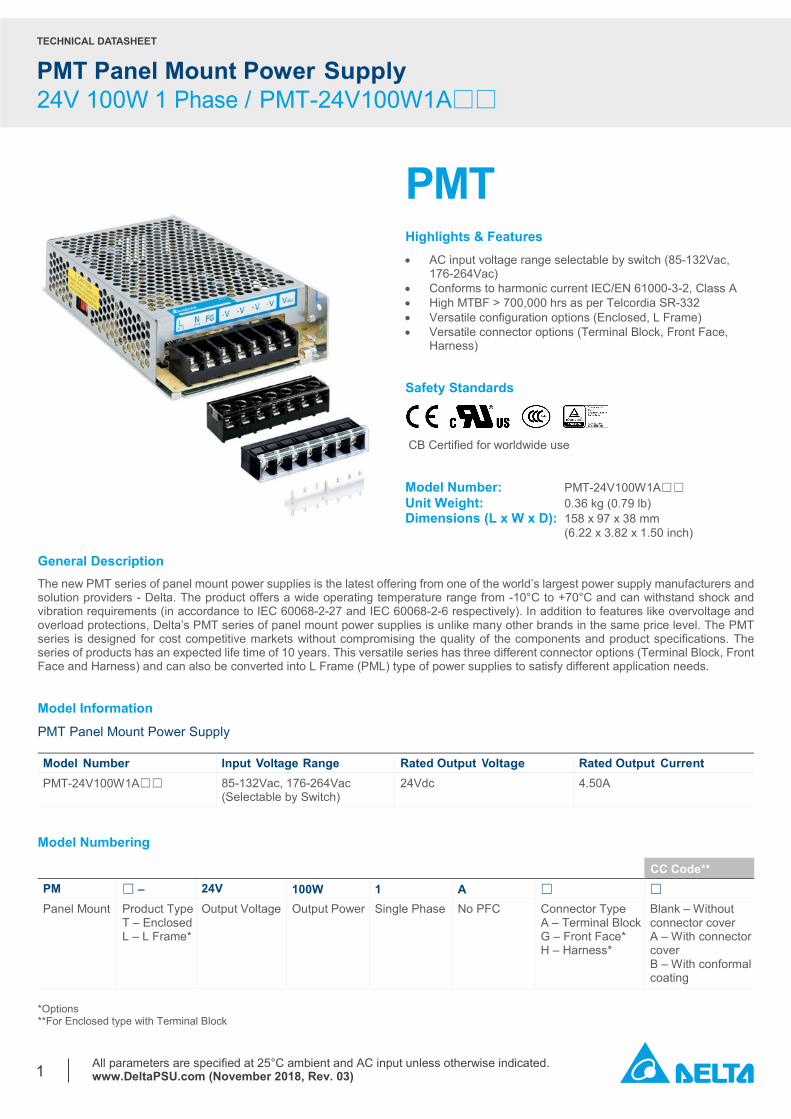
TECHNICAL DATASHEET PMT Panel Mount Power Supply 24V 100W 1 Phase / PMT-24V100W1A□□ All parameters are specified at 25°C ambient and AC input unless otherwise indicated. www.DeltaPSU.com (November 2018, Rev. 03) 1 PMT Highlights & Features • AC input voltage range selectable by switch (85-132Vac, 176-264Vac) • Conforms to harmonic current IEC/EN 61000-3-2, Class A • High MTBF > 700,000 hrs as per Telcordia SR-332 • Versatile configuration options (Enclosed, L Frame) • Versatile connector options (Terminal Block, Front Face, Harness) Safety Standards CB Certified for worldwide use Model Number: PMT-24V100W1A☐☐ Unit Weight: 0.36 kg (0.79 lb) Dimensions (L x W x D): 158 x 97 x 38 mm (6.22 x 3.82 x 1.50 inch) General Description The new PMT series of panel mount power supplies is the latest offering from one of the world’s largest power supply manufacturers and solution providers - Delta. The product offers a wide operating temperature range from -10°C to +70°C and can withstand shock and vibration requirements (in accordance to IEC 60068-2-27 and IEC 60068-2-6 respectively). In addition to features like overvoltage and overload protections, Delta’s PMT series of panel mount power supplies is unlike many other brands in the same price level. The PMT series is designed for cost competitive markets without compromising the quality of the components and product specifications. The series of products has an expected life time of 10 years. This versatile series has three different connector options (Terminal Block, Front Face and Harness) and can also be converted into L Frame (PML) type of power supplies to satisfy different application needs. Model Information PMT Panel Mount Power Supply Model Number Input Voltage Range Rated Output Voltage Rated Output Current PMT-24V100W1A☐☐ 85-132Vac, 176-264Vac (Selectable by Switch) 24Vdc 4.50A Model Numbering CC Code** PM □ – 24V 100W 1 A □ □ Panel Mount Product Type T – Enclosed L – L Frame* Output Voltage Output Power Single Phase No PFC Connector Type A – Terminal Block G – Front Face* H – Harness* Blank – Without connector cover A – With connector cover B – With conformal coating *Options **For Enclosed type with Terminal Block
Transcript of PMT-24V100W1Ax (November 2018, Rev. 03) · CB Certified for worldwide use Model Number:...
TECHNICAL DATASHEET
PMT Panel Mount Power Supply 24V 100W 1 Phase / PMT-24V100W1A□□
All parameters are specified at 25°C ambient and AC input unless otherwise indicated. www.DeltaPSU.com (November 2018, Rev. 03)
1
PMT Highlights & Features • AC input voltage range selectable by switch (85-132Vac,
176-264Vac) • Conforms to harmonic current IEC/EN 61000-3-2, Class A • High MTBF > 700,000 hrs as per Telcordia SR-332 • Versatile configuration options (Enclosed, L Frame) • Versatile connector options (Terminal Block, Front Face,
Harness)
Safety Standards
CB Certified for worldwide use
Model Number: PMT-24V100W1A☐☐ Unit Weight: 0.36 kg (0.79 lb) Dimensions (L x W x D): 158 x 97 x 38 mm
(6.22 x 3.82 x 1.50 inch) General Description The new PMT series of panel mount power supplies is the latest offering from one of the world’s largest power supply manufacturers and solution providers - Delta. The product offers a wide operating temperature range from -10°C to +70°C and can withstand shock and vibration requirements (in accordance to IEC 60068-2-27 and IEC 60068-2-6 respectively). In addition to features like overvoltage and overload protections, Delta’s PMT series of panel mount power supplies is unlike many other brands in the same price level. The PMT series is designed for cost competitive markets without compromising the quality of the components and product specifications. The series of products has an expected life time of 10 years. This versatile series has three different connector options (Terminal Block, Front Face and Harness) and can also be converted into L Frame (PML) type of power supplies to satisfy different application needs. Model Information PMT Panel Mount Power Supply Model Number Input Voltage Range Rated Output Voltage Rated Output Current PMT-24V100W1A☐☐ 85-132Vac, 176-264Vac
(Selectable by Switch) 24Vdc 4.50A
Model Numbering
CC Code** PM □ – 24V 100W 1 A □ □ Panel Mount Product Type
T – Enclosed L – L Frame*
Output Voltage Output Power Single Phase No PFC Connector Type A – Terminal Block G – Front Face* H – Harness*
Blank – Without connector cover A – With connector cover B – With conformal coating
*Options **For Enclosed type with Terminal Block
TECHNICAL DATASHEET
PMT Panel Mount Power Supply 24V 100W 1 Phase / PMT-24V100W1A□□
All parameters are specified at 25°C ambient and AC input unless otherwise indicated. www.DeltaPSU.com (November 2018, Rev. 03)
2
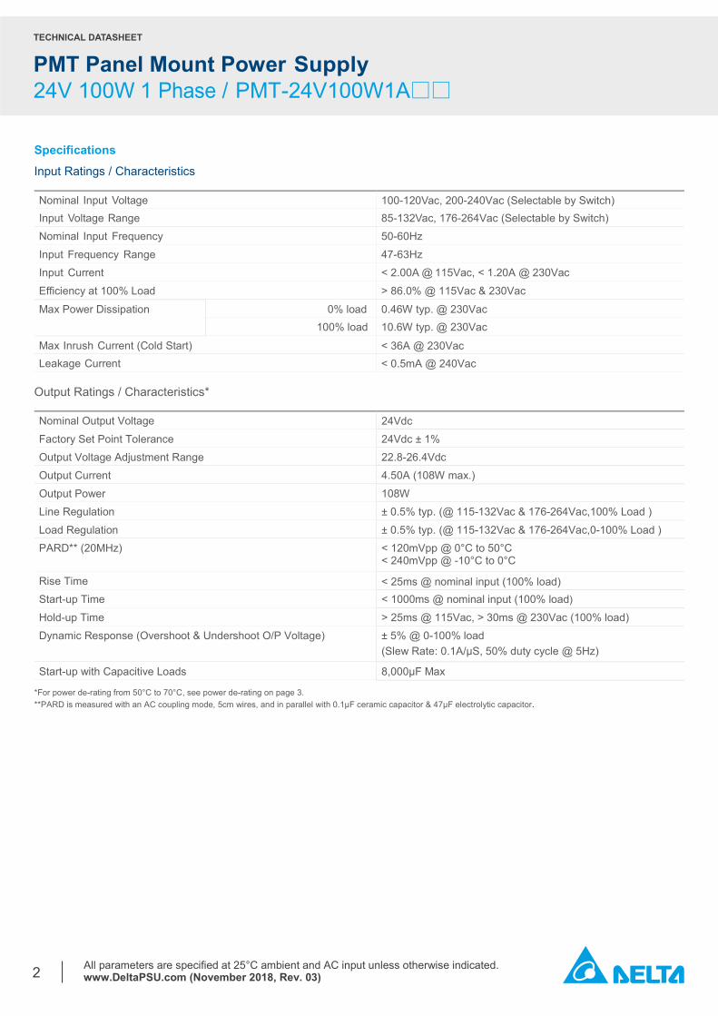
Specifications Input Ratings / Characteristics Nominal Input Voltage 100-120Vac, 200-240Vac (Selectable by Switch) Input Voltage Range 85-132Vac, 176-264Vac (Selectable by Switch) Nominal Input Frequency 50-60Hz Input Frequency Range 47-63Hz Input Current < 2.00A @ 115Vac, < 1.20A @ 230Vac Efficiency at 100% Load > 86.0% @ 115Vac & 230Vac Max Power Dissipation 0% load 0.46W typ. @ 230Vac 100% load 10.6W typ. @ 230Vac
Max Inrush Current (Cold Start) < 36A @ 230Vac Leakage Current < 0.5mA @ 240Vac
Output Ratings / Characteristics* Nominal Output Voltage 24Vdc Factory Set Point Tolerance 24Vdc ± 1% Output Voltage Adjustment Range 22.8-26.4Vdc Output Current 4.50A (108W max.) Output Power 108W Line Regulation ± 0.5% typ. (@ 115-132Vac & 176-264Vac,100% Load ) Load Regulation ± 0.5% typ. (@ 115-132Vac & 176-264Vac,0-100% Load ) PARD** (20MHz) < 120mVpp @ 0°C to 50°C
< 240mVpp @ -10°C to 0°C
Rise Time < 25ms @ nominal input (100% load) Start-up Time < 1000ms @ nominal input (100% load) Hold-up Time > 25ms @ 115Vac, > 30ms @ 230Vac (100% load)
Dynamic Response (Overshoot & Undershoot O/P Voltage) ± 5% @ 0-100% load (Slew Rate: 0.1A/μS, 50% duty cycle @ 5Hz)
Start-up with Capacitive Loads 8,000µF Max
*For power de-rating from 50°C to 70°C, see power de-rating on page 3. **PARD is measured with an AC coupling mode, 5cm wires, and in parallel with 0.1µF ceramic capacitor & 47µF electrolytic capacitor.
TECHNICAL DATASHEET
PMT Panel Mount Power Supply 24V 100W 1 Phase / PMT-24V100W1A□□
All parameters are specified at 25°C ambient and AC input unless otherwise indicated. www.DeltaPSU.com (November 2018, Rev. 03)
3
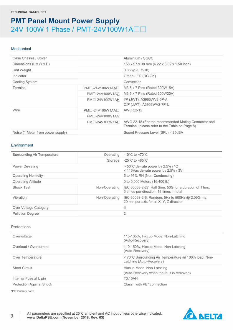
Mechanical Case Chassis / Cover Aluminium / SGCC Dimensions (L x W x D) 158 x 97 x 38 mm (6.22 x 3.82 x 1.50 inch)
Unit Weight 0.36 kg (0.79 lb) Indicator Green LED (DC OK) Cooling System Convection Terminal PM☐-24V100W1AA☐ M3.5 x 7 Pins (Rated 300V/15A) PM☐-24V100W1AG M3.5 x 7 Pins (Rated 300V/20A) PM☐-24V100W1AH I/P (JWT): A3963WV2-5P-A
O/P (JWT): A3963WV2-7P-U Wire PM☐-24V100W1AA☐ AWG 22-12 PM☐-24V100W1AG PM☐-24V100W1AH AWG 22-18 (For the recommended Mating Connector and
Terminal, please refer to the Table on Page 8)
Noise (1 Meter from power supply) Sound Pressure Level (SPL) < 25dBA Environment Surrounding Air Temperature Operating -10°C to +70°C Storage -25°C to +85°C Power De-rating > 50°C de-rate power by 2.5% / °C
< 115Vac de-rate power by 2.5% / 3V Operating Humidity 5 to 95% RH (Non-Condensing) Operating Altitude 0 to 5,000 Meters (16,400 ft.) Shock Test Non-Operating IEC 60068-2-27, Half Sine: 50G for a duration of 11ms,
3 times per direction, 18 times in total
Vibration Non-Operating IEC 60068-2-6, Random: 5Hz to 500Hz @ 2.09Grms, 20 min per axis for all X, Y, Z direction
Over Voltage Category II Pollution Degree 2
Protections Overvoltage 115-135%, Hiccup Mode, Non-Latching
(Auto-Recovery)
Overload / Overcurrent 110-150%, Hiccup Mode, Non-Latching (Auto-Recovery)
Over Temperature < 70°C Surrounding Air Temperature @ 100% load, Non-Latching (Auto-Recovery)
Short Circuit Hiccup Mode, Non-Latching (Auto-Recovery when the fault is removed)
Internal Fuse at L pin T3.15AH Protection Against Shock Class I with PE* connection
*PE: Primary Earth
TECHNICAL DATASHEET
PMT Panel Mount Power Supply 24V 100W 1 Phase / PMT-24V100W1A□□
All parameters are specified at 25°C ambient and AC input unless otherwise indicated. www.DeltaPSU.com (November 2018, Rev. 03)
4
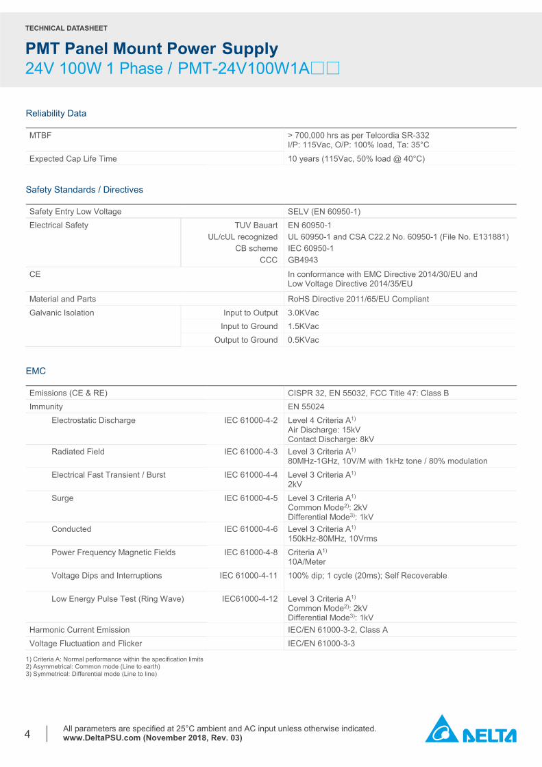
Reliability Data MTBF > 700,000 hrs as per Telcordia SR-332
I/P: 115Vac, O/P: 100% load, Ta: 35°C
Expected Cap Life Time 10 years (115Vac, 50% load @ 40°C) Safety Standards / Directives Safety Entry Low Voltage SELV (EN 60950-1) Electrical Safety TUV Bauart
UL/cUL recognized CB scheme
CCC
EN 60950-1 UL 60950-1 and CSA C22.2 No. 60950-1 (File No. E131881) IEC 60950-1 GB4943
CE In conformance with EMC Directive 2014/30/EU and Low Voltage Directive 2014/35/EU
Material and Parts RoHS Directive 2011/65/EU Compliant Galvanic Isolation Input to Output 3.0KVac Input to Ground 1.5KVac Output to Ground 0.5KVac
EMC Emissions (CE & RE) CISPR 32, EN 55032, FCC Title 47: Class B Immunity EN 55024
Electrostatic Discharge IEC 61000-4-2 Level 4 Criteria A1) Air Discharge: 15kV Contact Discharge: 8kV
Radiated Field IEC 61000-4-3 Level 3 Criteria A1) 80MHz-1GHz, 10V/M with 1kHz tone / 80% modulation
Electrical Fast Transient / Burst IEC 61000-4-4 Level 3 Criteria A1) 2kV
Surge IEC 61000-4-5 Level 3 Criteria A1) Common Mode2): 2kV Differential Mode3): 1kV
Conducted IEC 61000-4-6 Level 3 Criteria A1) 150kHz-80MHz, 10Vrms
Power Frequency Magnetic Fields IEC 61000-4-8 Criteria A1) 10A/Meter
Voltage Dips and Interruptions IEC 61000-4-11 100% dip; 1 cycle (20ms); Self Recoverable
Low Energy Pulse Test (Ring Wave) IEC61000-4-12 Level 3 Criteria A1) Common Mode2): 2kV Differential Mode3): 1kV
Harmonic Current Emission IEC/EN 61000-3-2, Class A Voltage Fluctuation and Flicker IEC/EN 61000-3-3
1) Criteria A: Normal performance within the specification limits 2) Asymmetrical: Common mode (Line to earth) 3) Symmetrical: Differential mode (Line to line)
TECHNICAL DATASHEET
PMT Panel Mount Power Supply 24V 100W 1 Phase / PMT-24V100W1A□□
All parameters are specified at 25°C ambient and AC input unless otherwise indicated. www.DeltaPSU.com (November 2018, Rev. 03)
5
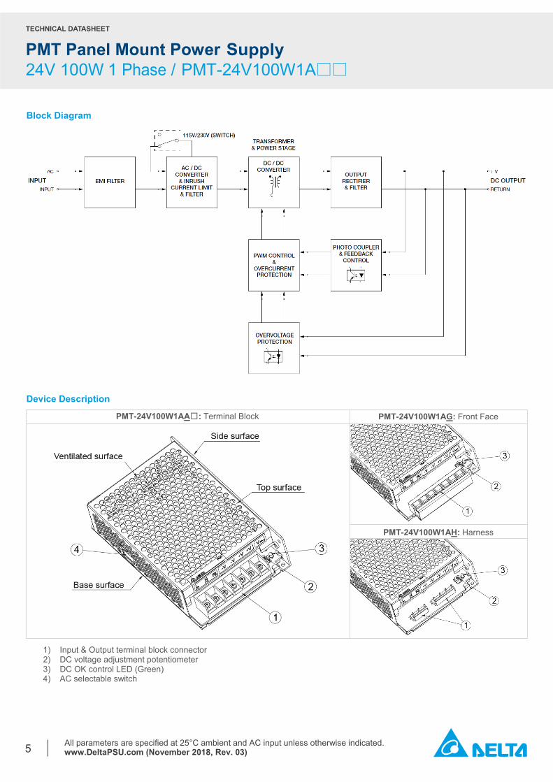
Block Diagram
Device Description
1) Input & Output terminal block connector 2) DC voltage adjustment potentiometer 3) DC OK control LED (Green) 4) AC selectable switch
PMT-24V100W1AH: Harness
PMT-24V100W1AA☐: Terminal Block PMT-24V100W1AG: Front Face
TECHNICAL DATASHEET
PMT Panel Mount Power Supply 24V 100W 1 Phase / PMT-24V100W1A□□
All parameters are specified at 25°C ambient and AC input unless otherwise indicated. www.DeltaPSU.com (November 2018, Rev. 03)
6
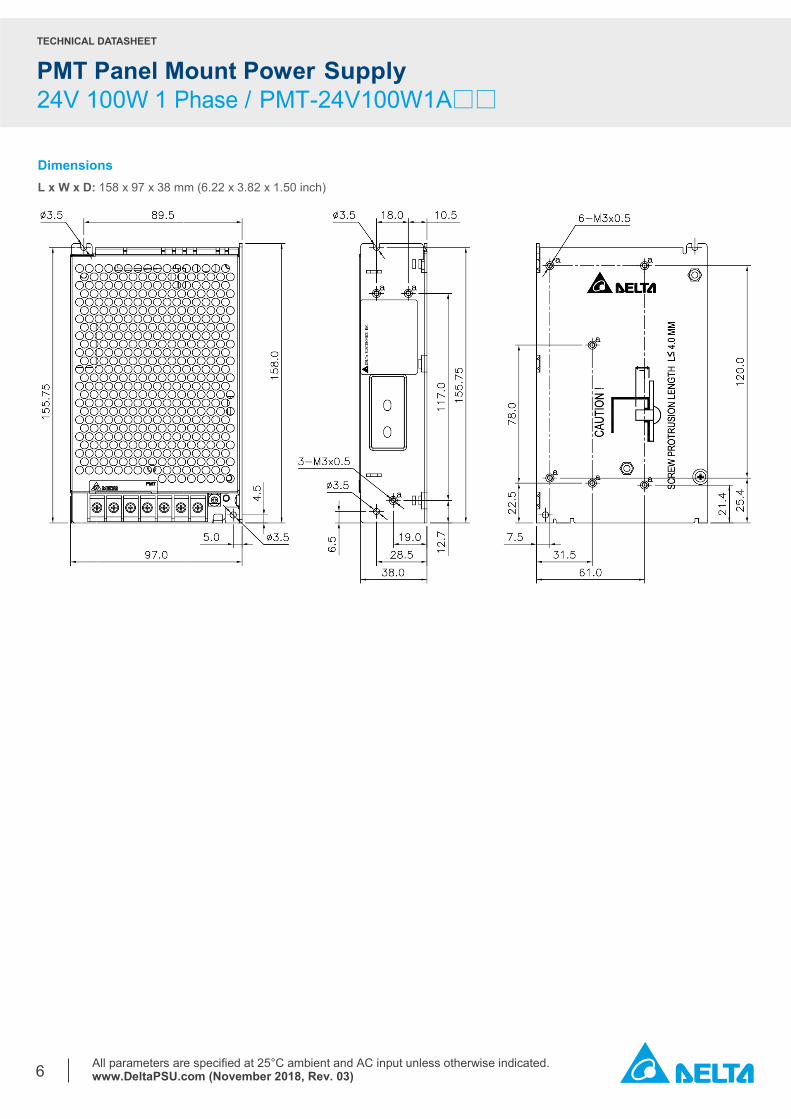
Dimensions L x W x D: 158 x 97 x 38 mm (6.22 x 3.82 x 1.50 inch)
TECHNICAL DATASHEET
PMT Panel Mount Power Supply 24V 100W 1 Phase / PMT-24V100W1A□□
All parameters are specified at 25°C ambient and AC input unless otherwise indicated. www.DeltaPSU.com (November 2018, Rev. 03)
7
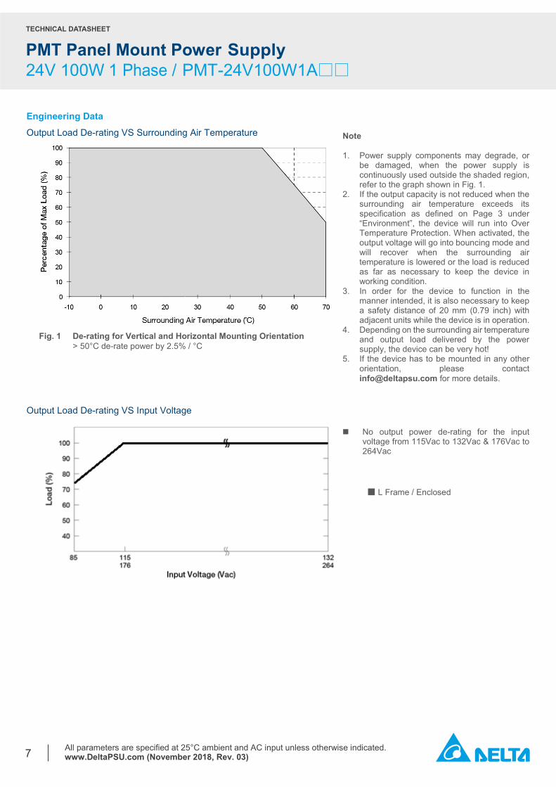
Engineering Data Output Load De-rating VS Surrounding Air Temperature
Output Load De-rating VS Input Voltage
Note 1. Power supply components may degrade, or
be damaged, when the power supply is continuously used outside the shaded region, refer to the graph shown in Fig. 1.
2. If the output capacity is not reduced when the surrounding air temperature exceeds its specification as defined on Page 3 under “Environment”, the device will run into Over Temperature Protection. When activated, the output voltage will go into bouncing mode and will recover when the surrounding air temperature is lowered or the load is reduced as far as necessary to keep the device in working condition.
3. In order for the device to function in the manner intended, it is also necessary to keep a safety distance of 20 mm (0.79 inch) with adjacent units while the device is in operation.
4. Depending on the surrounding air temperature and output load delivered by the power supply, the device can be very hot!
5. If the device has to be mounted in any other orientation, please contact [email protected] for more details.
Fig. 1 De-rating for Vertical and Horizontal Mounting Orientation > 50°C de-rate power by 2.5% / °C
No output power de-rating for the input voltage from 115Vac to 132Vac & 176Vac to 264Vac ■ L Frame / Enclosed
TECHNICAL DATASHEET
PMT Panel Mount Power Supply 24V 100W 1 Phase / PMT-24V100W1A□□
All parameters are specified at 25°C ambient and AC input unless otherwise indicated. www.DeltaPSU.com (November 2018, Rev. 03)
8
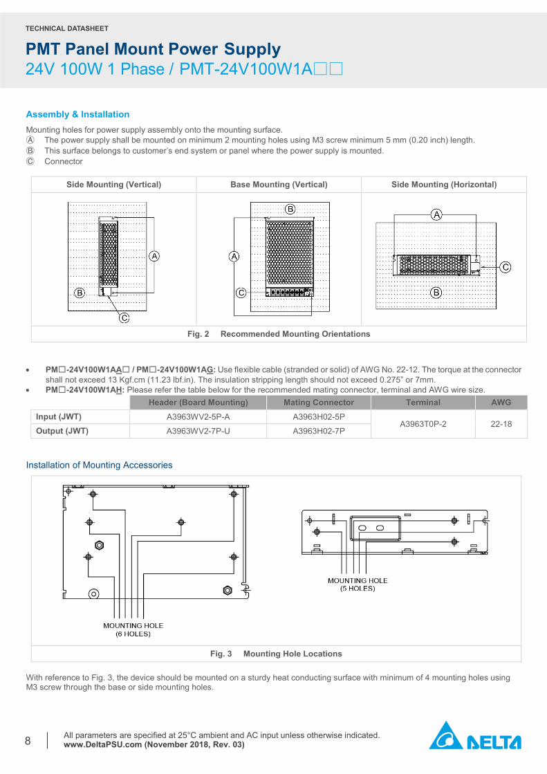
Assembly & Installation Mounting holes for power supply assembly onto the mounting surface. Ⓐ The power supply shall be mounted on minimum 2 mounting holes using M3 screw minimum 5 mm (0.20 inch) length. Ⓑ This surface belongs to customer’s end system or panel where the power supply is mounted. Ⓒ Connector
Side Mounting (Vertical) Base Mounting (Vertical) Side Mounting (Horizontal)
Fig. 2 Recommended Mounting Orientations
• PM☐-24V100W1AA☐ / PM☐-24V100W1AG: Use flexible cable (stranded or solid) of AWG No. 22-12. The torque at the connector
shall not exceed 13 Kgf.cm (11.23 lbf.in). The insulation stripping length should not exceed 0.275” or 7mm. • PM☐-24V100W1AH: Please refer the table below for the recommended mating connector, terminal and AWG wire size.
Header (Board Mounting) Mating Connector Terminal AWG Input (JWT) A3963WV2-5P-A A3963H02-5P
A3963T0P-2 22-18 Output (JWT) A3963WV2-7P-U A3963H02-7P
Installation of Mounting Accessories
Fig. 3 Mounting Hole Locations With reference to Fig. 3, the device should be mounted on a sturdy heat conducting surface with minimum of 4 mounting holes using M3 screw through the base or side mounting holes.
TECHNICAL DATASHEET
PMT Panel Mount Power Supply 24V 100W 1 Phase / PMT-24V100W1A□□
All parameters are specified at 25°C ambient and AC input unless otherwise indicated. www.DeltaPSU.com (November 2018, Rev. 03)
9
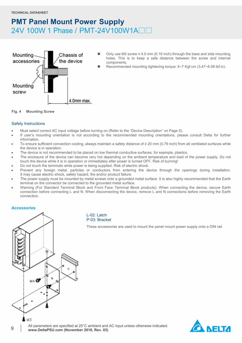
Fig. 4 Mounting Screw Safety Instructions
• Must select correct AC input voltage before turning on (Refer to the “Device Description” on Page 5). • If user’s mounting orientation is not according to the recommended mounting orientations, please consult Delta for further
information. • To ensure sufficient convection cooling, always maintain a safety distance of ≥ 20 mm (0.79 inch) from all ventilated surfaces while
the device is in operation. • The device is not recommended to be placed on low thermal conductive surfaces, for example, plastics. • The enclosure of the device can become very hot depending on the ambient temperature and load of the power supply. Do not
touch the device while it is in operation or immediately after power is turned OFF. Risk of burning! • Do not touch the terminals while power is being supplied. Risk of electric shock. • Prevent any foreign metal, particles or conductors from entering the device through the openings during installation.
It may cause electric shock, safety hazard, fire and/or product failure. • The power supply must be mounted by metal screws onto a grounded metal surface. It is also highly recommended that the Earth
terminal on the connector be connected to the grounded metal surface. • Warning (For Standard Terminal Block and Front Face Terminal Block products): When connecting the device, secure Earth
connection before connecting L and N. When disconnecting the device, remove L and N connections before removing the Earth connection.
Accessories
L-02: Latch P-03: Bracket These accessories are used to mount the panel mount power supply onto a DIN rail.
Only use M3 screw ≤ 4.0 mm (0.16 inch) through the base and side mounting holes. This is to keep a safe distance between the screw and internal components.
Recommended mounting tightening torque: 4~7 Kgf.cm (3.47~6.08 lbf.in).
TECHNICAL DATASHEET
PMT Panel Mount Power Supply 24V 100W 1 Phase / PMT-24V100W1A□□
All parameters are specified at 25°C ambient and AC input unless otherwise indicated. www.DeltaPSU.com (November 2018, Rev. 03)
10
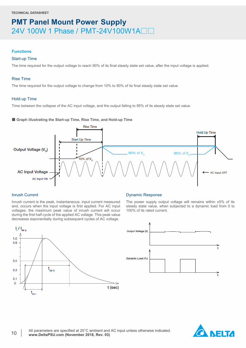
Functions Start-up Time The time required for the output voltage to reach 90% of its final steady state set value, after the input voltage is applied. Rise Time The time required for the output voltage to change from 10% to 90% of its final steady state set value. Hold-up Time Time between the collapse of the AC input voltage, and the output falling to 95% of its steady state set value. ■ Graph illustrating the Start-up Time, Rise Time, and Hold-up Time
Inrush Current Inrush current is the peak, instantaneous, input current measured and, occurs when the input voltage is first applied. For AC input voltages, the maximum peak value of inrush current will occur during the first half cycle of the applied AC voltage. This peak value decreases exponentially during subsequent cycles of AC voltage.
Dynamic Response The power supply output voltage will remains within ±5% of its steady state value, when subjected to a dynamic load from 0 to 100% of its rated current.
TECHNICAL DATASHEET
PMT Panel Mount Power Supply 24V 100W 1 Phase / PMT-24V100W1A□□
All parameters are specified at 25°C ambient and AC input unless otherwise indicated. www.DeltaPSU.com (November 2018, Rev. 03)
11
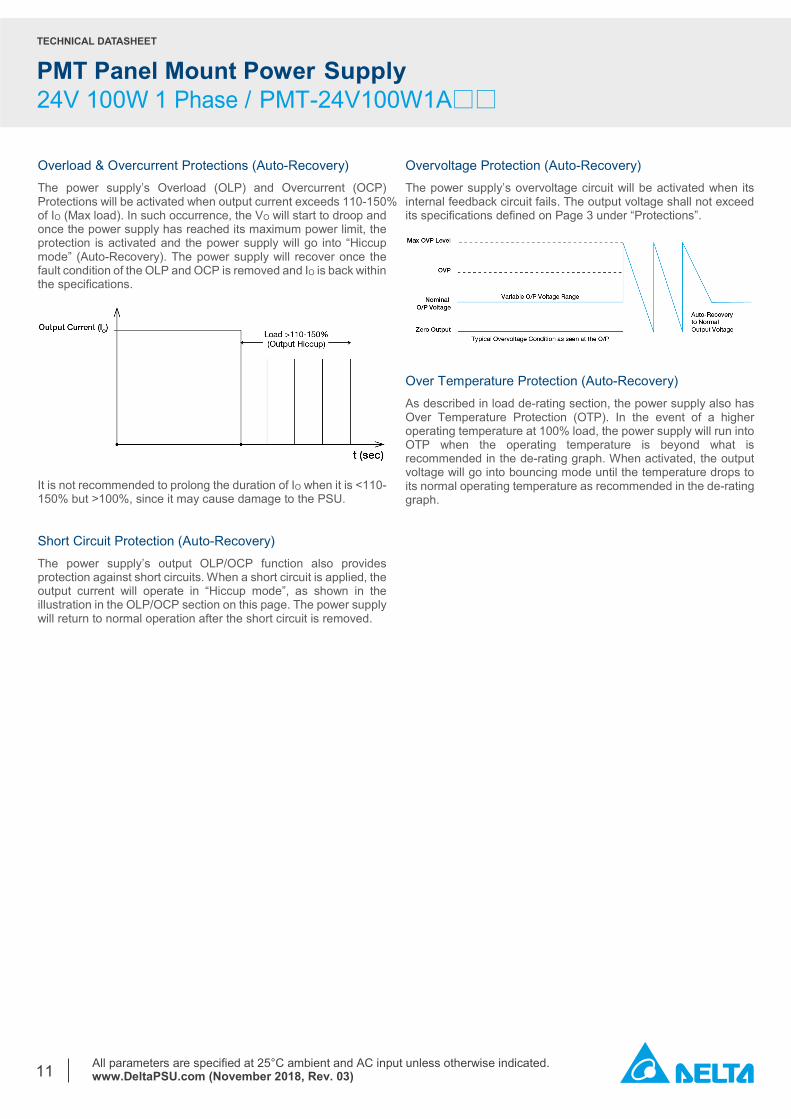
Overload & Overcurrent Protections (Auto-Recovery) The power supply’s Overload (OLP) and Overcurrent (OCP) Protections will be activated when output current exceeds 110-150% of IO (Max load). In such occurrence, the VO will start to droop and once the power supply has reached its maximum power limit, the protection is activated and the power supply will go into “Hiccup mode” (Auto-Recovery). The power supply will recover once the fault condition of the OLP and OCP is removed and IO is back within the specifications.
It is not recommended to prolong the duration of IO when it is <110-150% but >100%, since it may cause damage to the PSU.
Overvoltage Protection (Auto-Recovery) The power supply’s overvoltage circuit will be activated when its internal feedback circuit fails. The output voltage shall not exceed its specifications defined on Page 3 under “Protections”.
Over Temperature Protection (Auto-Recovery) As described in load de-rating section, the power supply also has Over Temperature Protection (OTP). In the event of a higher operating temperature at 100% load, the power supply will run into OTP when the operating temperature is beyond what is recommended in the de-rating graph. When activated, the output voltage will go into bouncing mode until the temperature drops to its normal operating temperature as recommended in the de-rating graph.
Short Circuit Protection (Auto-Recovery) The power supply’s output OLP/OCP function also provides protection against short circuits. When a short circuit is applied, the output current will operate in “Hiccup mode”, as shown in the illustration in the OLP/OCP section on this page. The power supply will return to normal operation after the short circuit is removed.
TECHNICAL DATASHEET
PMT Panel Mount Power Supply 24V 100W 1 Phase / PMT-24V100W1A□□
All parameters are specified at 25°C ambient and AC input unless otherwise indicated. www.DeltaPSU.com (November 2018, Rev. 03)
12
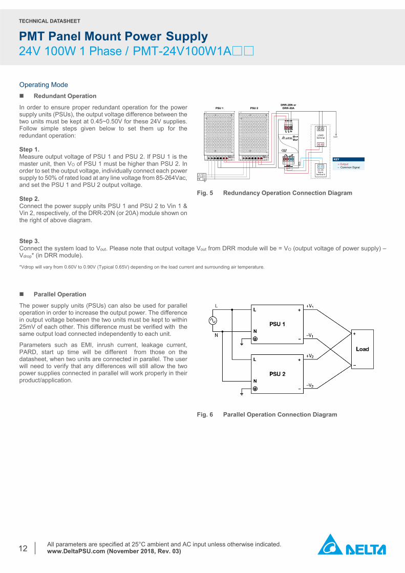
Operating Mode Redundant Operation
In order to ensure proper redundant operation for the power supply units (PSUs), the output voltage difference between the two units must be kept at 0.45~0.50V for these 24V supplies. Follow simple steps given below to set them up for the redundant operation: Step 1. Measure output voltage of PSU 1 and PSU 2. If PSU 1 is the master unit, then VO of PSU 1 must be higher than PSU 2. In order to set the output voltage, individually connect each power supply to 50% of rated load at any line voltage from 85-264Vac, and set the PSU 1 and PSU 2 output voltage. Step 2. Connect the power supply units PSU 1 and PSU 2 to Vin 1 & Vin 2, respectively, of the DRR-20N (or 20A) module shown on the right of above diagram.
Fig. 5 Redundancy Operation Connection Diagram
Step 3. Connect the system load to Vout. Please note that output voltage Vout from DRR module will be = VO (output voltage of power supply) – Vdrop* (in DRR module). *Vdrop will vary from 0.60V to 0.90V (Typical 0.65V) depending on the load current and surrounding air temperature. Parallel Operation
The power supply units (PSUs) can also be used for parallel operation in order to increase the output power. The difference in output voltage between the two units must be kept to within 25mV of each other. This difference must be verified with the same output load connected independently to each unit.
Parameters such as EMI, inrush current, leakage current, PARD, start up time will be different from those on the datasheet, when two units are connected in parallel. The user will need to verify that any differences will still allow the two power supplies connected in parallel will work properly in their product/application.
Fig. 6 Parallel Operation Connection Diagram
PSU 2PSU 1DRR-20N or
DRR-20A
L (L1)N (L2)PE
+ Output– Common Signal
KEY
LOADTerminal Com
DC OKSignal
Terminal N
TECHNICAL DATASHEET
PMT Panel Mount Power Supply 24V 100W 1 Phase / PMT-24V100W1A□□
All parameters are specified at 25°C ambient and AC input unless otherwise indicated. www.DeltaPSU.com (November 2018, Rev. 03)
13
Others Delta RoHS Compliant
Restriction of the usage of hazardous substances
The European directive 2011/65/EU limits the maximum impurity level of homogeneous materials such as lead, mercury, cadmium, chrome, polybrominated flame retardants PBB and PBDE for the use in electrical and electronic equipment. RoHS is the abbreviation for “Restriction of the use of certain hazardous substances in electrical and electronic equipment”.
This product conforms to this standard.
PFC – Norm EN 61000-3-2
Line Current Harmonic content
Typically, the input current waveform is not sinusoidal due to the periodical peak charging of the input capacitor. In industrial environment, complying with EN 61000-3-2 is only necessary under special conditions. Complying to this standard can have some technical drawbacks, such as lower efficiency as well as some commercial aspects such as higher purchasing costs. Frequently, the user does not profit from fulfilling this standard, therefore, it is important to know whether it is mandatory to meet this standard for a specific application.
Attention Delta provides all information in the datasheets on an “AS IS” basis and does not offer any kind of warranty through the information for using the product. In the event of any discrepancy between the information in the catalog and datasheets, the datasheets shall prevail (please refer to www.DeltaPSU.com for the latest datasheets information). Delta shall have no liability of indemnification for any claim or action arising from any error for the provided information in the datasheets. Customer shall take its responsibility for evaluation of using the product before placing an order with Delta. Delta reserves the right to make changes to the information described in the datasheets without notice.
Mouser Electronics
Authorized Distributor
Click to View Pricing, Inventory, Delivery & Lifecycle Information: Delta Electronics:
PMT-24V100W1AA PML-24V100W1AA PML-24V100W1AG PML-24V100W1AH PMT-24V100W1AG PMT-
24V100W1AH