Olympus PMT-35TA and PMT-35RA Photomacrographic System ... · PMT-35TA PMT-35RA This instruction...
27
PHOTOMACROGRAPHIC SYSTEM MODELS PMT-35TA PMT-35RA This instructi on manual is for use of the Photomacrographic System Model PMT-35A. We recomm end you read the manual carefully in ord er to familiarize you rse lf f ully wi th th eu se of this system so that you can obtain maximum performance. The photomacrographic syst em PM T-35A is divi ded into two types, incl ud ing Model PMT-35TA (for transmitted light) and Model PMT·3 5RA (for reflected li ght). OLYMPUS
Transcript of Olympus PMT-35TA and PMT-35RA Photomacrographic System ... · PMT-35TA PMT-35RA This instruction...
PHOTOMACROGRAPHIC SYSTEM
MODELS
PMT-35TAPMT-35RA
This instruction manual is for use of the Photomacrographic
System Model PMT-35A. We recommend you read the manual
carefully in order to familiarize yourself fully with the use of
this system so that you can obtain maximum performance.
The photomacrographic system PMT-35A is divided into two
types, including Model PMT-35TA (for transmitted light) and
Model PM T·35RA (for reflected light).
OLYMPUS
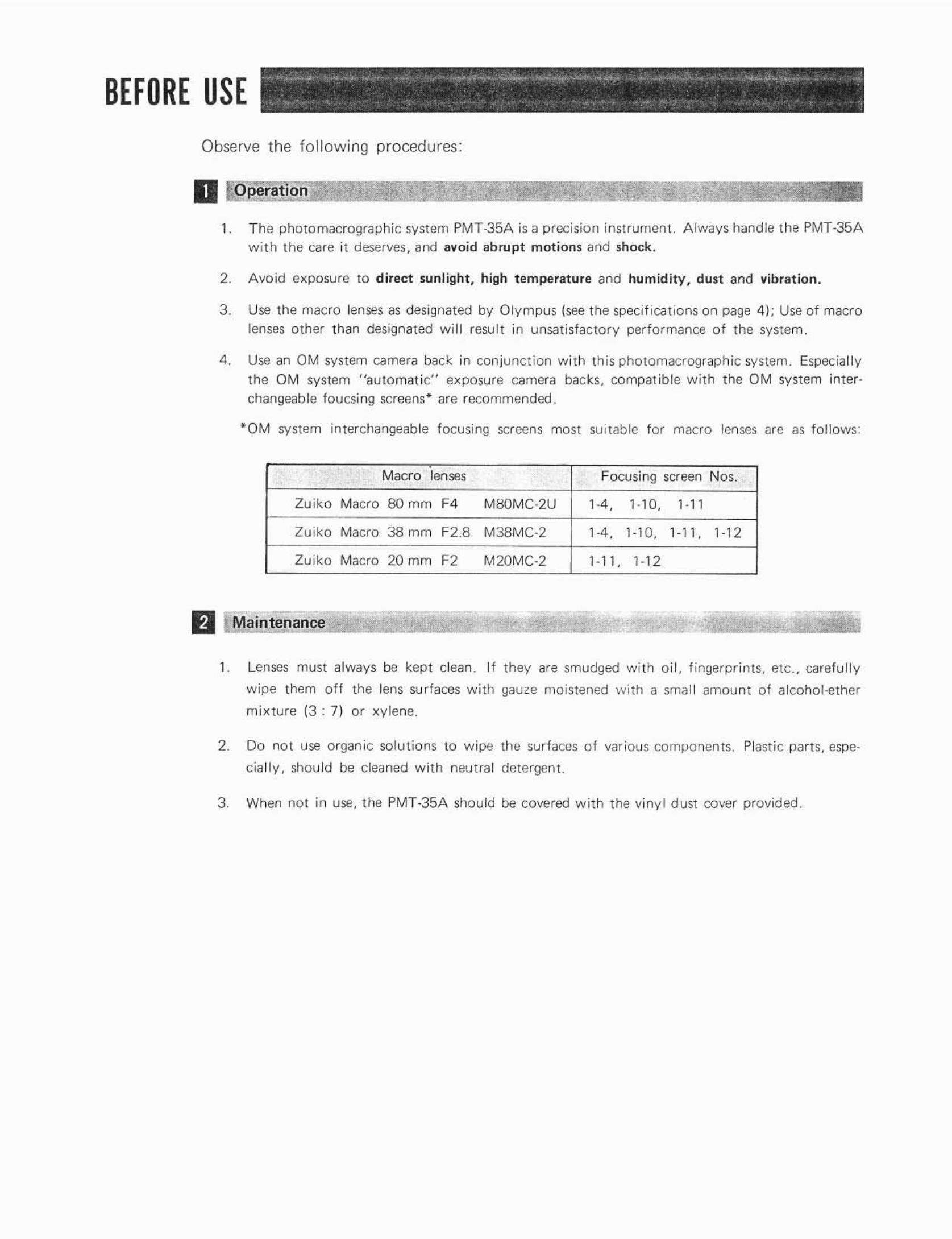
BEFORE USEObserve the foll owi ng procedures:
D Operat1 o
1. T he photomacrographic system PMT-35A is a precision instrument. A lways hand le the PMT-35Awith the care it deserves, and avoid abru pt motions and shock.
2. Avoid exposure to direct sunlight , high t emperature and hum idity . dust and vibrat ion.
3. Use the macro lenses as designated by Olympus (see the speci f ica t ions on page 4); Use of macrolenses othe r than designa ted will resu lt in unsatisfactory performance o f the system.
4. Use an OM system camera back in conjunction with th is photomacrographic system. Especiall yt he OM system "au tomatic" exposure camera backs, compa t ib le w ith t he OM system interchangeab le toucsing screens" are recommended .
· OM system interchangeable focusing screens most su itable for macro lenses are as foll ows:
Macro lenses Focusing screen Nos.
Zu iko Macro BOmm F4 MBOMC.2U 1·4, 1·10, 1-11
Zu iko Macro 38mm F2.8 M38MC·2 1·4, 1·10, 1-11, 1-12
Zu iko Macro 20 mm F2 M20MC·2 1-11, 1-12
fJ Maintenance
1. Lenses must always be kept clean. If they are smudged w ith o i l , f ingerpr ints, etc.. carefully
w ipe them off the lens su rfaces w ith gauze moistened with a small amount of alcohol -ether
mixture (3 : 7) or xy lene.
2. Do no t use organ ic solutions to w ipe the surfaces o f var ious components. Plast ic parts , espe
ciall y , shou ld be cleaned w ith neutra l detergent.
3. When not in use, the PMT-35A should be covered w ith t he viny l dust cover provided.
CONTENTS. ~ . . ,/'
. '". "-
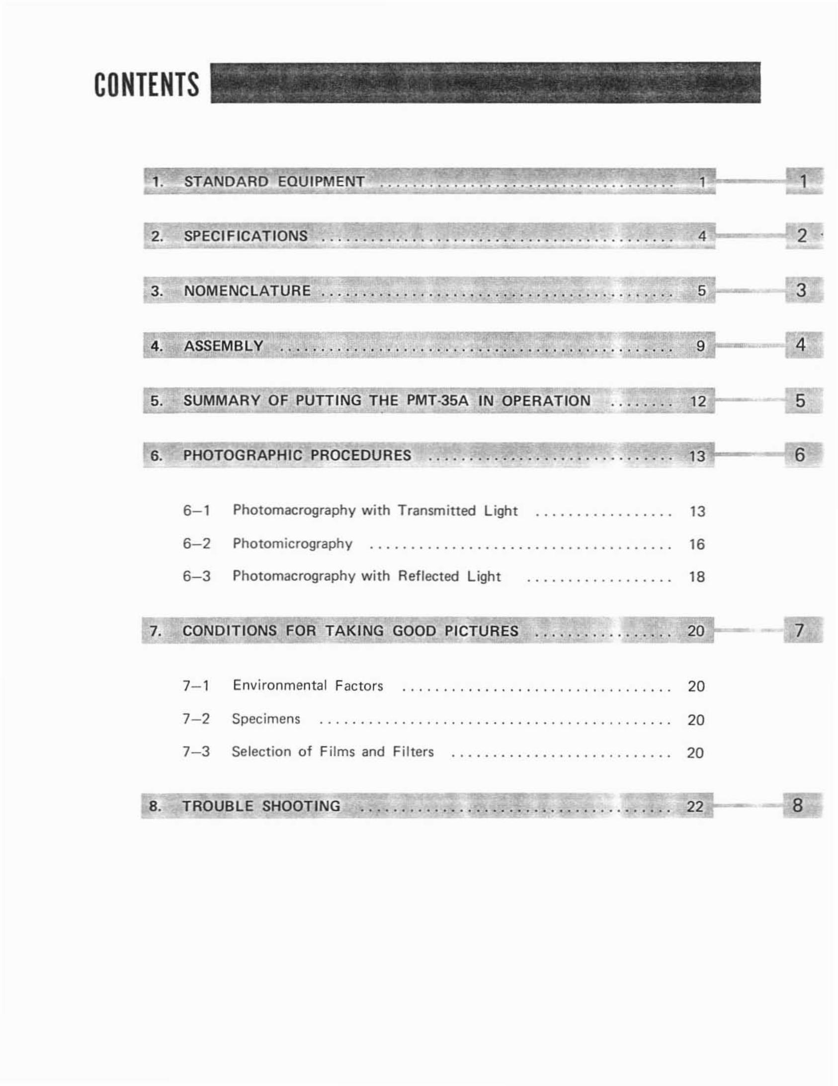
1. STAND ARD EOUIPMENT 1 1
2. SPECiFiCATIONS :.~. .: .:.:.=4~-- - 2 .
3. NOMENC LATURE . .... . . . . ... .. . ... . . . . . . . . . . . . . .. . . . . . . . . . . 5 3
4. ASSEMBLY :..: .:.:. .:.=]9~---ll!:
5. SUMMARY OF PUTTING THE PMT·35A IN OPERATION 5
6
6- 1
6-2
6- 3
Photomacrography with Transmitted Light
Photomicrography .
Photomacrography with Reflected Light
13
16
18
7. CONDITIONS FOR TAKING GOOO PICTURES 20 7
Selection of Films and Filters 20
Environmental Factors7- 1
7- 2
7- 3
Specimens
... , . . . . . . . . . . . . . . . . . . . . . . . . . . . . .
. . . . . . . . . . . . .. , . .... . .. . . . . . . . . . . . . . . . . . . . .
20
20
8. TROUBLE SHOOTING · 22:2i1--- 8
I STANDARD EQUIPMENT ~ ..;< _. • .-,- .. ... ,,~-. ~ . -~. , "
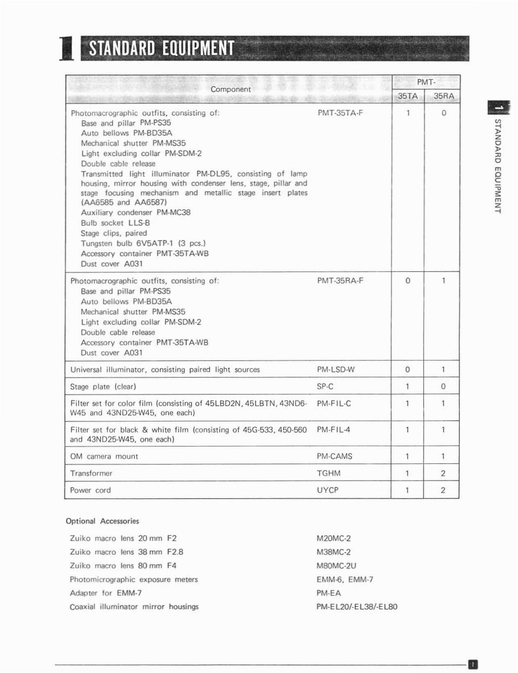
PMT-Component
35TA 35RA
Pho tomacrographic ou tfits, consisting of: PMT-35TA-F 1 0Base and pillar PM-PS35A uto bellows PM-BD35AMechanical shutter PM-MS35L ight excluding co llar PM-SDM-2
Double cable releaseTransmitted light illuminator PM-D L95, consisti ng of lamphousi ng, mirror housing with condenser lens, stage, p illar andSlage focusing mechanism and metallic Slage insert plates(AA6585 and AA6587)Auxiliary condenser PM·MC38Bulb socket LLS-BStage clips. pairedTungsten bul b 6V5ATP-l (3 pcs .]
Accessory container PMT-35TAWaDust cover A 031
Photomacrograph ic outf its, consisting o f : PMT-35RA- F 0 1Base and pillar PM-PS35Auto bellows PM-BD35AMechanical shutter PM·MS35Light excluding collar PM·SDM·2Doub le cab le releaseAccessory container PMT-35TA -WBDust cover A03 1
Universal i lluminator . consist ing paired l ight sources PM·lSO-W 0 1
Stage plate (clear) SP·C 1 0
Filter set for color fi lm (consisting of 45 lBD2N, 45LBTN. 43N D6- PM·F l l ·C 1 1W45 and 43ND25W45. one each)
Filter set for black & white f ilm {consisti ng of 45G-533, 450·560 PM·F 1L4 1 1and 43N D25-W4 5, one each)
OM camera mou nt PM·CAMS 1 1
Transfor mer TGHM 1 2
Power cord uvcr 1 2
Optional Accessories
~"o,.'"omoC-e
'"m"-l
Zuiko macro lens 20 mm F2
Zuikc macro lens 38 mm F2.8
Zuiko macro lens 80 mm F4
Photomicrographic exposure meters
Adapter for EMM·7
Coaxial illuminator mirror housings
M20MC-2
M38MC·2
M80MC·2U
EMM-6. EMM-7
PM·EA
PM·El20/·E l 38/ ·EL80
- - - - --- - - - - - - - - - --- - - - - - 0
u ,
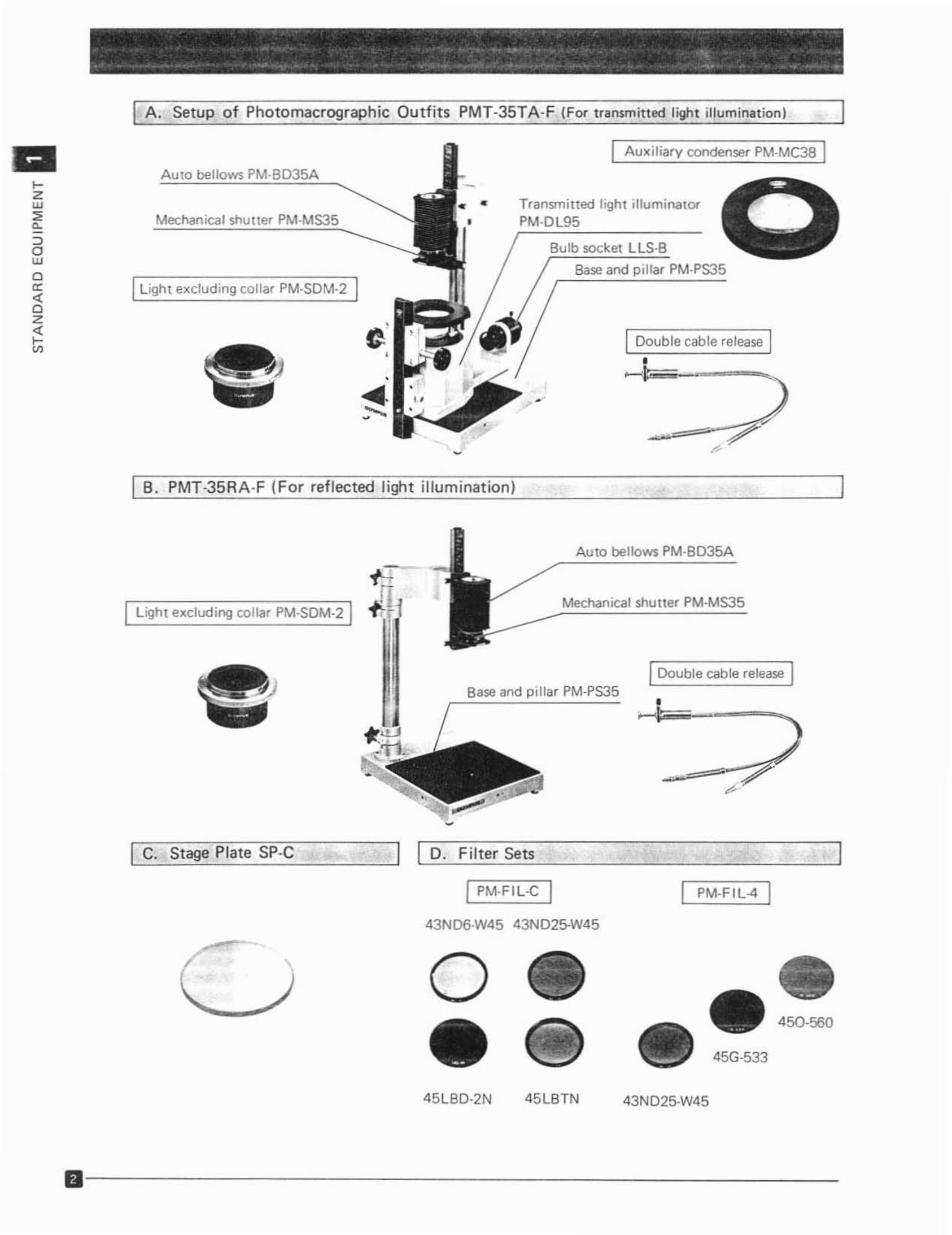
~ ~ - . .. ...I A. Setup of Photo macrographic Outfits PMT·35TA· F (For transmitted light illumination)
I Awc i liary condenser PM-MC3B I
IDouble cable release I•- 1--=
Bu lb socket LlS·B
Base and pillar PM·PS35
Tra nsm itted light illuminatorPM·Dl95
•
Auto bellows PM·BD35A
ILight excluding collar PM·SDM·2 I
>zw
"e,
::>awac:
'"oz'"t;;
I B. PMT-35RA·F (For reflected light ill uminat ion)
Auto bellows PM·BD35A
IDouble ca ble re lease I•
~l'==---_
Mechanical shu t ter PM-MS35
Base and pillar PM-PS35
I Light excluding collar PM.SDM-2 1
II PM-FI L" I
L:::---"'=--'--"=-=--=--- I I D. Filter Sets
I PM-FI L-C
43ND6W45 43ND25W45
I C. Stage Plate SP-C
o•45G·533
450-560
45LBTN 43ND25·W45
1lI- - - - - - - - - - - - - - - - - - - - - -
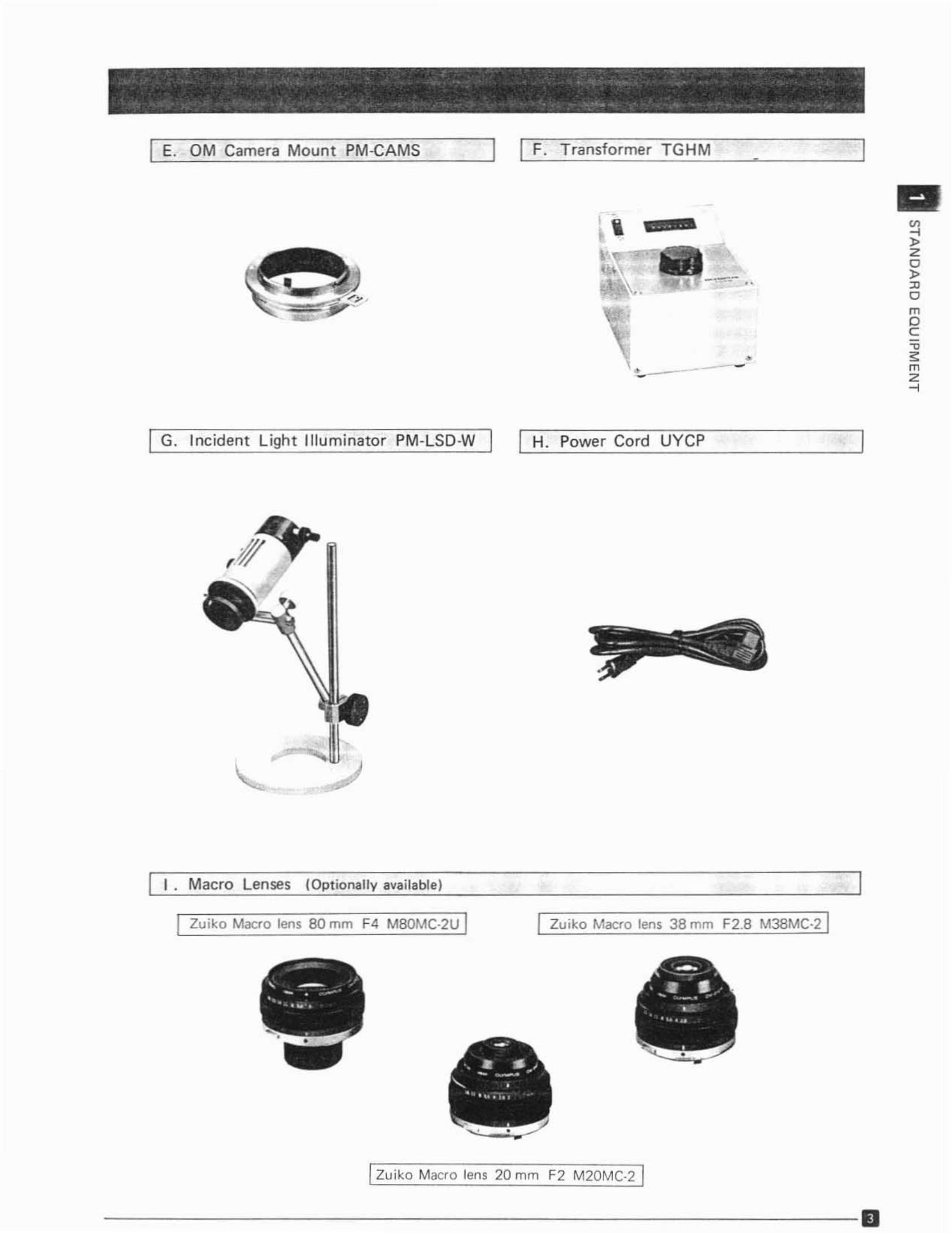
I E. OM Camera Mount PM-CAMS I F. Transformer TGHM•
IIIG ~...,.
zo
-~-
,.• • '"o
m0C-c
• "• - - m- z...
I G. Incident Light Illuminator PM·LSD·W I I H. Power Cord UYCP
•
I . Macro Lenses (Optionally available)
Zuiko Macro lens 80 mm F4 MBOMC·2U I I Zuiko Macro lens 38 mm F2.B M38MC.21
IZuiko Macro lens 20 mm F2 M20MC·2 I
-------- - - - - - --- - - - - - - 0
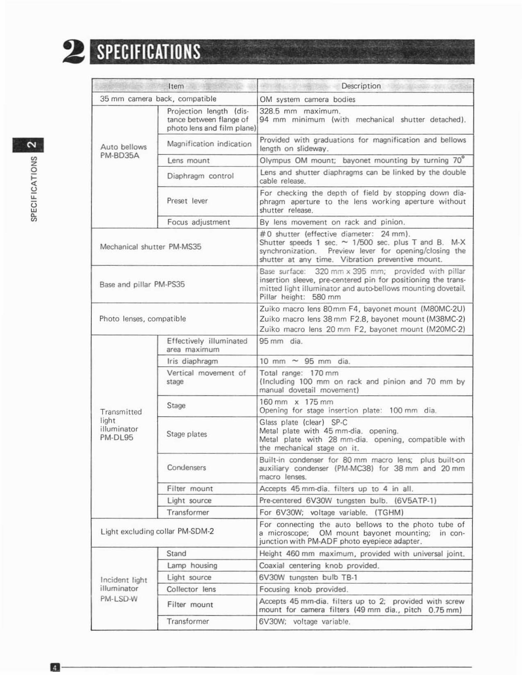
SPECIFICATIONS _ _ .
Item Description
35 mm camera back, compatib le OM system camera bod ies
Pro jection length (dis- 328.5 mm maximum.lance between flange o f 94 mm nummum (with mechanical shutter detached).photo lens and f ilm plane)
Magnif icat ion ind ication Provided w ith graduat ions for magnif icat ion and bellowsAuto bellows length on shdewav.PM-BD35A
Lens moun t Olympus OM mount; bayonet mounting by turn ing 700
Diaphragm contro l Lens and shutter d iaphragms can be li nked by the doublecable release.
FO' checking t he depth o f f ield by slopping down dla-Prese t lever phragm aperture to the lens work ing aperture without
shutter release.
Focu s ad justment By lens movement on rack and p inion .
#0 shu tter {effective diameter : 24 mm J.Sh utter speeds 1 sec. - 11500 sec. plus T and B. M·X
Mechanical shutter PM·MS35 synchron ization. Preview lever for opening/closing theshutter at any t ime. Vibration preventive mount.
Base surface : 320 mrr. x 395 mm; provided w ith p illar
Base and pillar PM·PS35inser tion sleeve, pre -centered p in for po sit ioning the trans-mined l igh t i ll uminator and auto-bellows mounting dovetail.Pi llar height : 580mm
Zui ko macro lens 80mm F4 , bayonet mount (M80MC·2U)Photo lenses, compatible Zuiko macro lens 38 mm F2.8, bayonet mount (M38MC·2)
z utko macro lens 20 mm F2, bayonet mount (M20MC·2 )
Effect ively illuminated 95mm dia.area maxrmurn
Ir is diaphragm 10 mm - 95 mm dia.
Vertical movement of Total range: 170 mm
""" (Includ ing 100 mm on rack and pinion and 70 mm bymanual doveta il movement )
Stage 160 mm x 175 mmTransmitted Opening for stage insertion plate: l 00 mm d ia.light Glass p late (clear ) SP·cil lum inator
Stage plates Metal p late w ith 45 mm-dia. cper unq.PM·DL95 Metal p late with 28 rnm-d!a. opening, compatible with
the mechanical stage on it.
Bui lt-in condenser for 80 mm macro lens; plus built-enCondensers auxiliary condenser (PM-MC38) fo' 38mm and 20mm
macro lenses.
Filter mount Accepts 45 mm-dia. fi lters up to 4 in au.Light source Pre-centered 6V3f.JN tungsten bu lb. (6V5ATP-1)
Transformer For 6V3(JoN; vol tage var iable. ITGHM I
Fo' connecti ng tne auto bellows to the photo tube ofLight excluding collar PM-SDM-2 a rmcroscooe: OM mount bayonet mounting; m con-
junct ion w ith PM·AD F photo eyepiece adapter.
Stand Heigh t 460 mm maximum, provided with universal jo int.
WImp housing Coaxial centering knob provided.
Incident light Light source 6V3(}N tungsten bu lb TB·l
i llum inator Collector lens Focusing knob provided .PM-LSD W
Fi lter mount Accepts 45 rnm-dia. f ilters up to 2; provided with screwmount to- camera fi lters {49 mm dia., pitch 0 .75 mm J
Transformer 6V30W; voltage variable.
11 - - - - - - - - - - - - - - - - - - - - - - - -
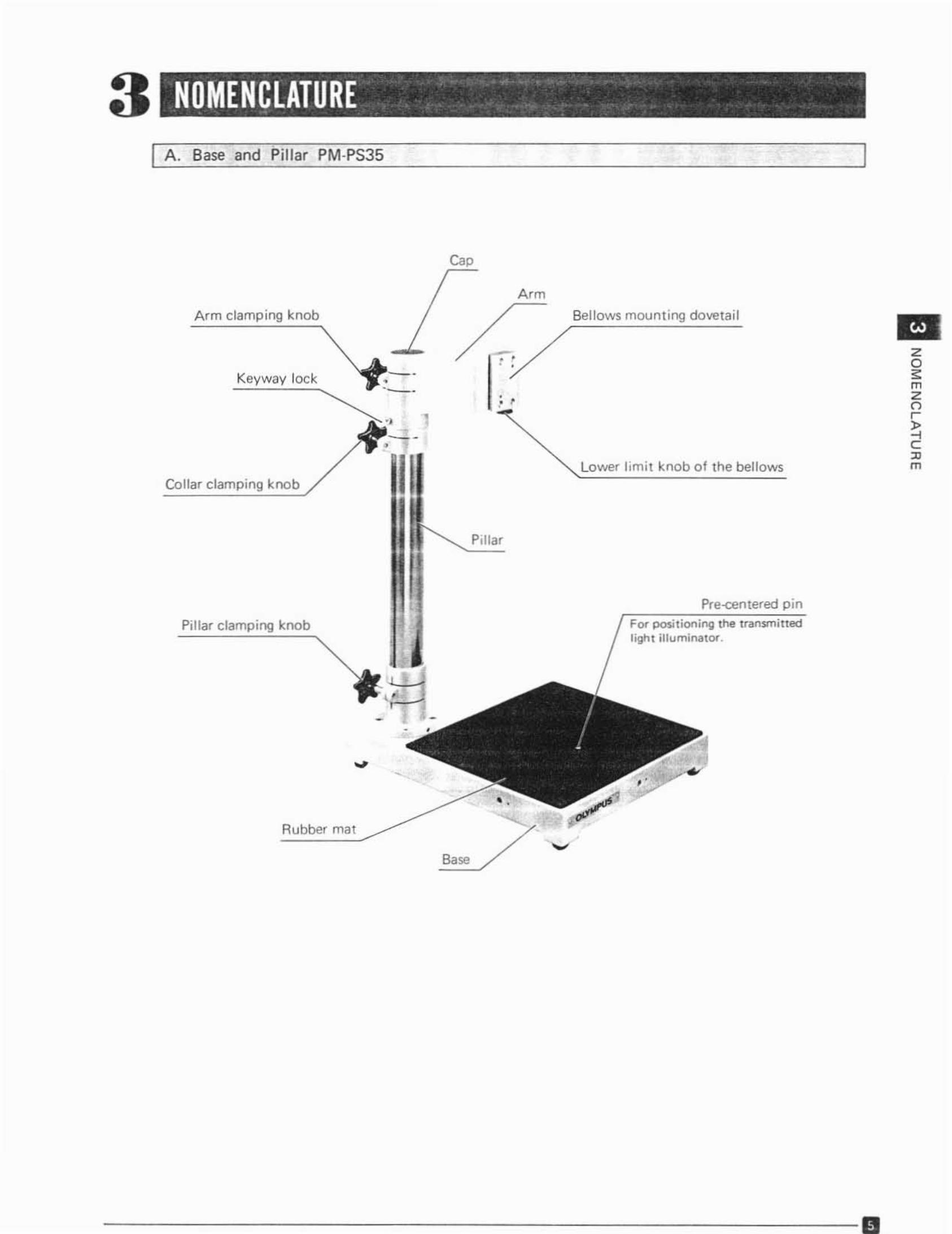
3 NOMENCLATURE .
A. Base and Pillar PM·PS35
Cap
zo
"mZor-
~"m
I!!I
Pre-centered p inFor POSi tion ing the tran$lTl in edlight illuminator .
Lower l imit knob of the bell ows
Bellows moun ting dovetail
A' m
•..~/• •
Pilla r
B""
••
- -
~..- -•
I
Rubber mat
Keyway lock
Arm clamping knob
Pillar clamping knob
Collar clamping k l')Qb
- - - - - - - --- ------- - - - - --- 0
~ .•• • - 0- _~ _ . __ • , ,.... -.......- ..._ ~ _
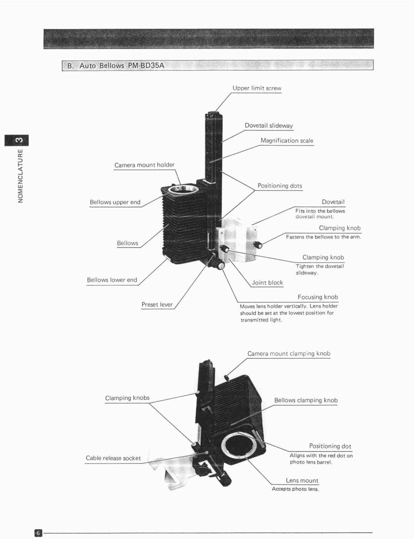
I B. Auto Bellows PM-BD35A
ur
'"::>3ozw
"oz
Camera mount holder
Bellows upper end
Bellows
Bellows lower end
Preset lever
Upper limi t screw
Doveta il slidewav
Magnif icat ion scale
Posit ioning dots
Doveta il
Fi ts into the be llow sdo~eta il mount.
Clamping knob
Clamping knobTigh ten the dovetai lsuoewav.
Joint block
Focusing knob
Moves lens holder vert ica lly. Lens holdershould be set at the lowest position fortransmi tted light .
Camera mount clamping knob
Clamping kno bs
Cable release socket
Bellows clamping knob
Posit ion ing dot
A ligns wi th t he red do t onpho to lens bar rel.
l ens mountAccepts photo lens .
11---- - - - - - --- - - - - - - -
• •.' .-' ~., "' . "",," • L
. , . . . . .
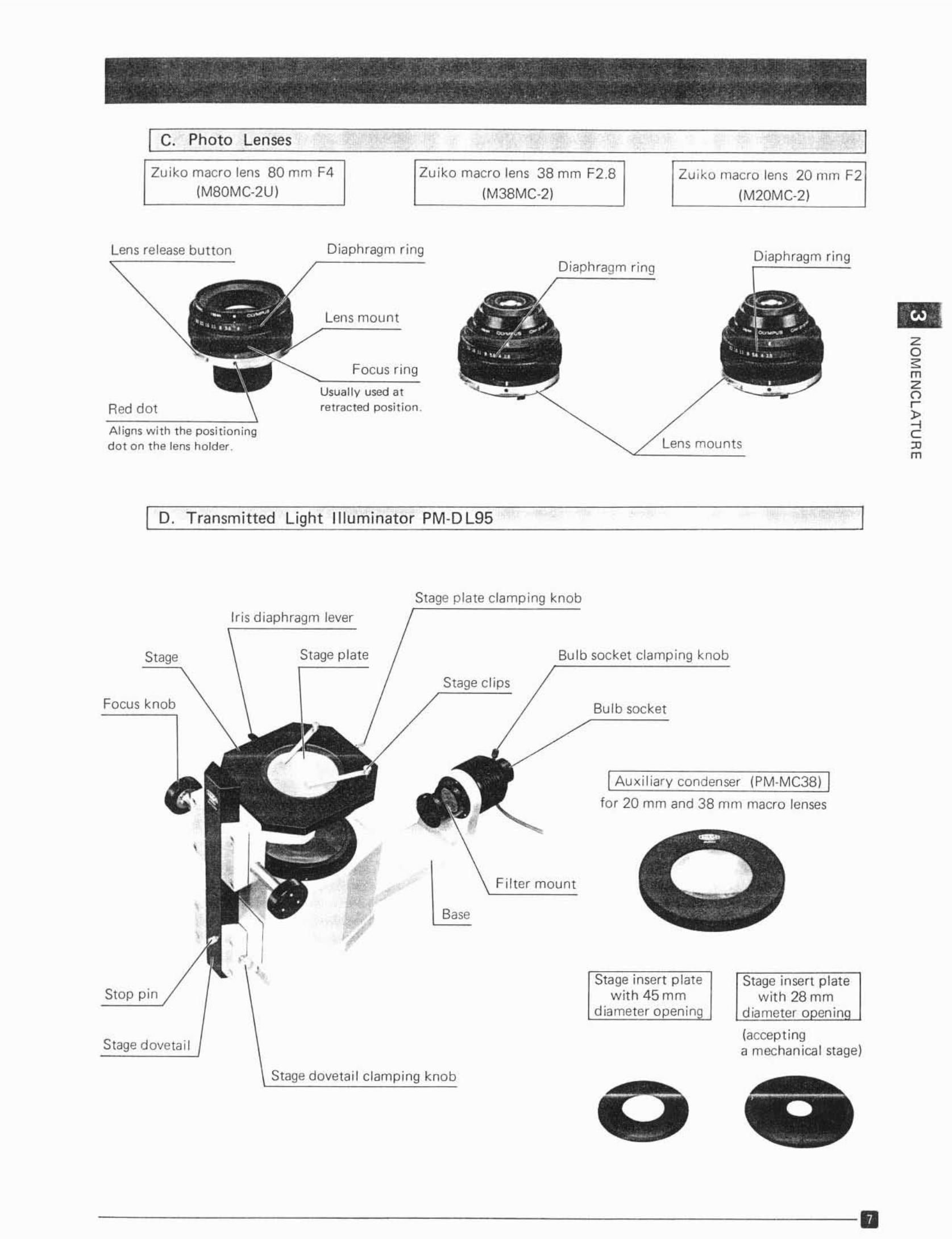
I C Photo Lenses•
Zui ko macro lens 80 mm F4 Zuiko macro lens 38 mm F2.8 Zui ko macro lens 20 rum F2(M80MC-2U) (M38MC·2( (M20MC·2 )
Lens release button
Red dot
Aligns wi th the p osi t ion ingdot on the lens holder
Diaphragm ring
Lens mount
Focus ring
Usua lly used a tretracted posit ion.
Diaphragm ring
Lens mounts
Diaphragm ring
zo
"mZor-
"....c:'"m
I D. Transmitted Light Illuminato r PM-DL9S
Stage plate clamping knob
Iris diaphragm lever
Stage Stage plate Bulb socket clamping knob
1Au xiliary condenser (pM·MC38) I
for 20 mm and 38 mm macro lenses
Focus knob
Stop pin
Stage dovetail
Stage clips
Filter mOUn!
Base
Bulb socket
Stage insert p lat ew it h 45 01 01
diameter open in
Stage insert platewith 28 01 01
diameter oneninn
(accept inga mechan ica l stage)
Stage dovetail clamping knob
--------- ---------- 0
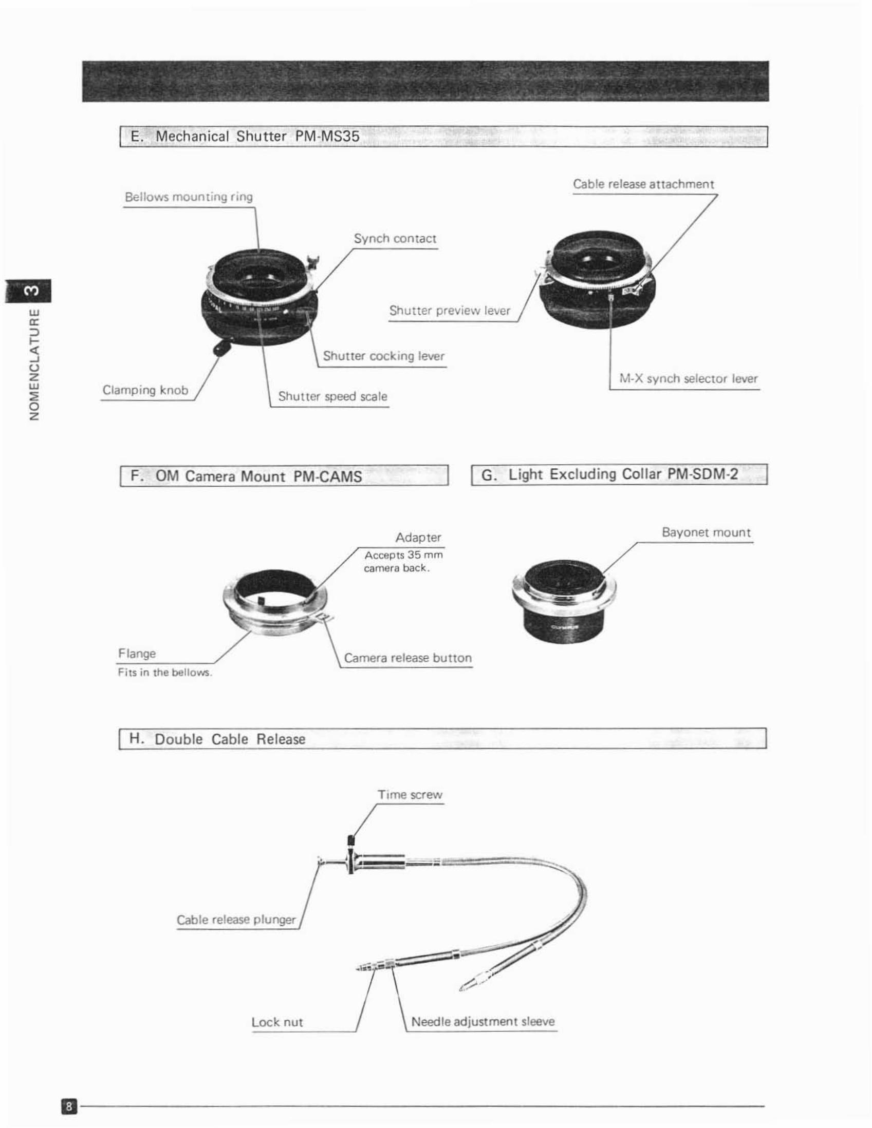
I E. Mechanical Shutter PM -MS35
Cab le release attachmentBellows mounting r ing
M·X synch selector lever
Shutter pre .... iew le....er
Shutter coc king lever
Shutter speed scale
Synch contact
Clamping knob
wori''"~uzw
"oz
I F. OM Camera Mount PM-CAMS I G. Ught Exclud ing Collar PM·SOM·2
Flange
Fi ts in the bellows.
AdapterAccepts 35 mmcamera beck .
Camera release button
Bayonet mount
I H. Double Cable Release
Time screw
Cable release plunger
.•"....,,",.=--e,"'-' ..-:?:,-? .»
Loc k. nut Need le adjustment sleeve
1iI - - - - - - - - - - - - - - - - - - -
4• •
,ASSEMBLY. . ;:;'. -: -:',- ..:;,: ' . '
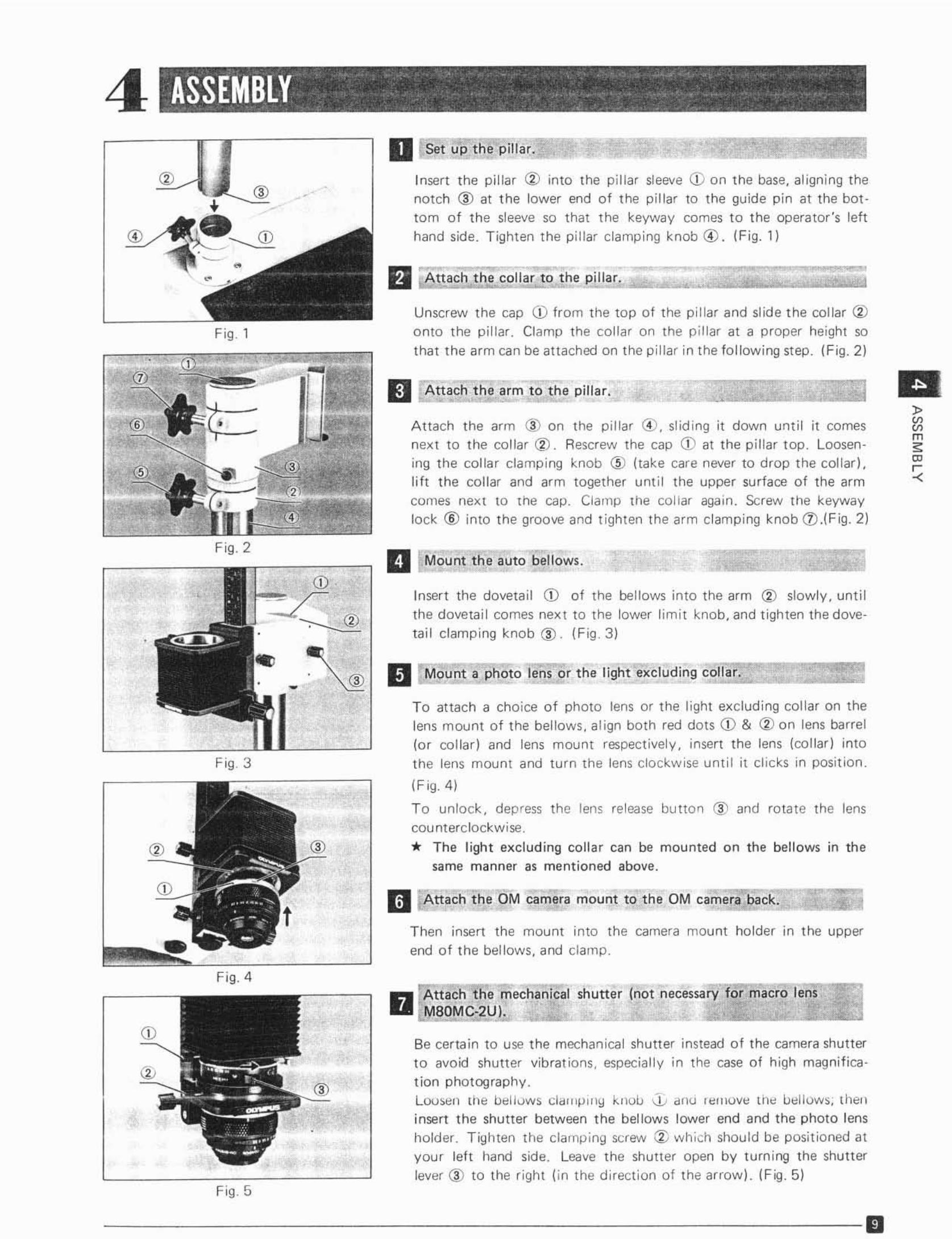
Attach t he arm (3,) on the pillar 00 . slid ing it down until it comesnext to t he colla r @ . Rescrew the cap CD at t he p ill ar top. Loosening t he colla r clamp ing knob @ (take care never to drop the collar),lift t he collar and arm together until the upper surface of the armcomes next to the cap. Clamp the collar agai n. Screw the keywaylock ® into the groove and t ighten the arm clamp ing knob CV.( Fig. 2 )
D Set u p the pillar..
Insert the pillar @ into the pillar sl eeve Q) on t he base, aligni ng thenotch @ at t he lower end of the pillar to the guide pin at the bot tom of the sleeve so that the keyway comes to t he operator 's lefthand side. Tighten t he pillar clamp ing knob ® . (F ig. 1)
II Attach the collar to· the, . p~i~II~'~'.":::':·;:·:·~::::::::::i
Unscrew the cap Q) from t he top of the p illar and slide t he collar <Vonto the pillar. Clamp the cottar on the p illar at a proper height sothat the arm can be attached on the pi llar in the following step. (Fig.2)
II Attach t he arm t o the pilla r.
Fig 1
-II
® • L
Fig . 2 1:1 Mount t il e auto bellows.
Insert the dovetail CD of the bellows into the arm ® slow ly, unt ilthe dovetai l comes next to the lower lim it knob, and t ighten the do vetai l clamp ing knob ® . (F ig,3)
_~ Ell Mount a p etc lens or the light excluding c~o~"~,~, ,::::::::==To attach a cho ice o f photo lens or the light excluding collar on thelens mount of the bellows, al ign both red dots CD & CV on lens barrel(o r collar] and lens mount respectively, insert the lens (collar) into
Fig.3 the lens mount and turn the lens clockw ise unt il it cl ic ks In position.
(F ig. 4 )
To un lock, depress the lens release button ~) and rotate the lenscounterclockwise.
* The l ight excl ud ing co llar can be mounted on the bell ows in thesame manner as mentioned above.
II r6ttach t he OM camera mount to the OM camera back.
Then insert the mount into the camera mount ho lder in the upperend of the bellows. and clamp.
Fig.4
CDD Attacn t lie mecnanical shutter (not necessary for macro tens
M80M C-2UI.
Be certain to use t he mechan ical shutt er instead o f t he camera shutterto avoid shutter vibrat ions. especially in the case of high magnifica·
t fon photography .Loosen me bettows ddllllJl lI>l knob J., anc 1I::11l0W the bellows, theninsert the shutter between the bellows lower end and the photo lensholder. T iyhten the clamp ing screw ::1; which should be posit ioned atyour left hand side. Leave the shutter open by turn ing the shutterlever (3) to the right (in the direction of the arrow). (Fig. 5)
Fig.5
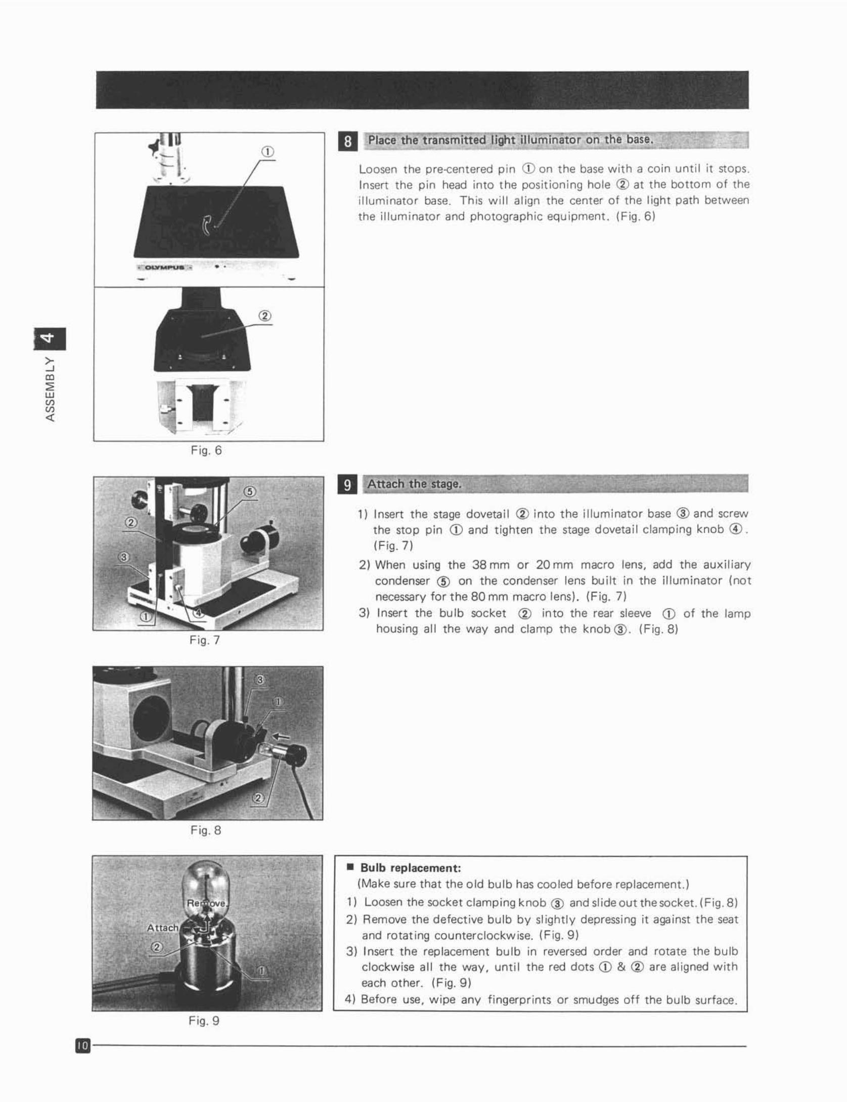
II ~Iace t l'ie t ransmitteCl ig t 11 umlnator on li1)~'~~"~'~.:::::::::1
Loosen the pre-centered p in CD on t he base w ith a co in unt il it stops
Insert the pin head into the position ing hole ® at the bottom o f theill umi nato r base. This will align the cen ter of the lig ht path between
the illum inator and photographic equ ipment. (Fig.61
---.. _.-
:I:Fig. 6
11 \<\ttach the stage.
1) Insert the stage dovetai l <V into the illuminator base ® and screw
the sto p pin CD and t ighten the stage dovetail clamping knob CD .(Fig.7)
2) When using the 38 mm or 20 mm macro lens, add the au xiliarycondenser @ on the condenser lens built in the illuminato r (not
necessary for t he 80 mm macro lens) . (Fig . 7)
3) Inser t the bulb socket <V into the rear sleeve CD of the lamphousing all the way and clamp the knob@ . (Fig.8)
Fig.8
Fig. 9
• Bulb replacement:(Make sure that the old bulb has cooled before replacernent.I
l ] Loosen the socket clam ping knob @ and slide out the socket . (Fig . 8)
2) Remove the defective bulb by slightly depress ing it against the seat
and rota ting counterclockw ise. (F ig. 9)
3 ) Insert the replacement bulb in reversed order and rota te the bu lbclockwise all the way. unt il the red dots CD & <V are aligned witheach other. (Fig. 9)
4 ) Befo re use, w ipe any f ingerpr ints or smudges oft the bul b su rface.
ID-- - --- - - - - ---- - - - ----
. ~' .. ,.. . . ",.. ,~,....,.~.,." ..~ .. .
!
Fig, 10
Fig, 11
Fig. 12
Fig, 13
GJ
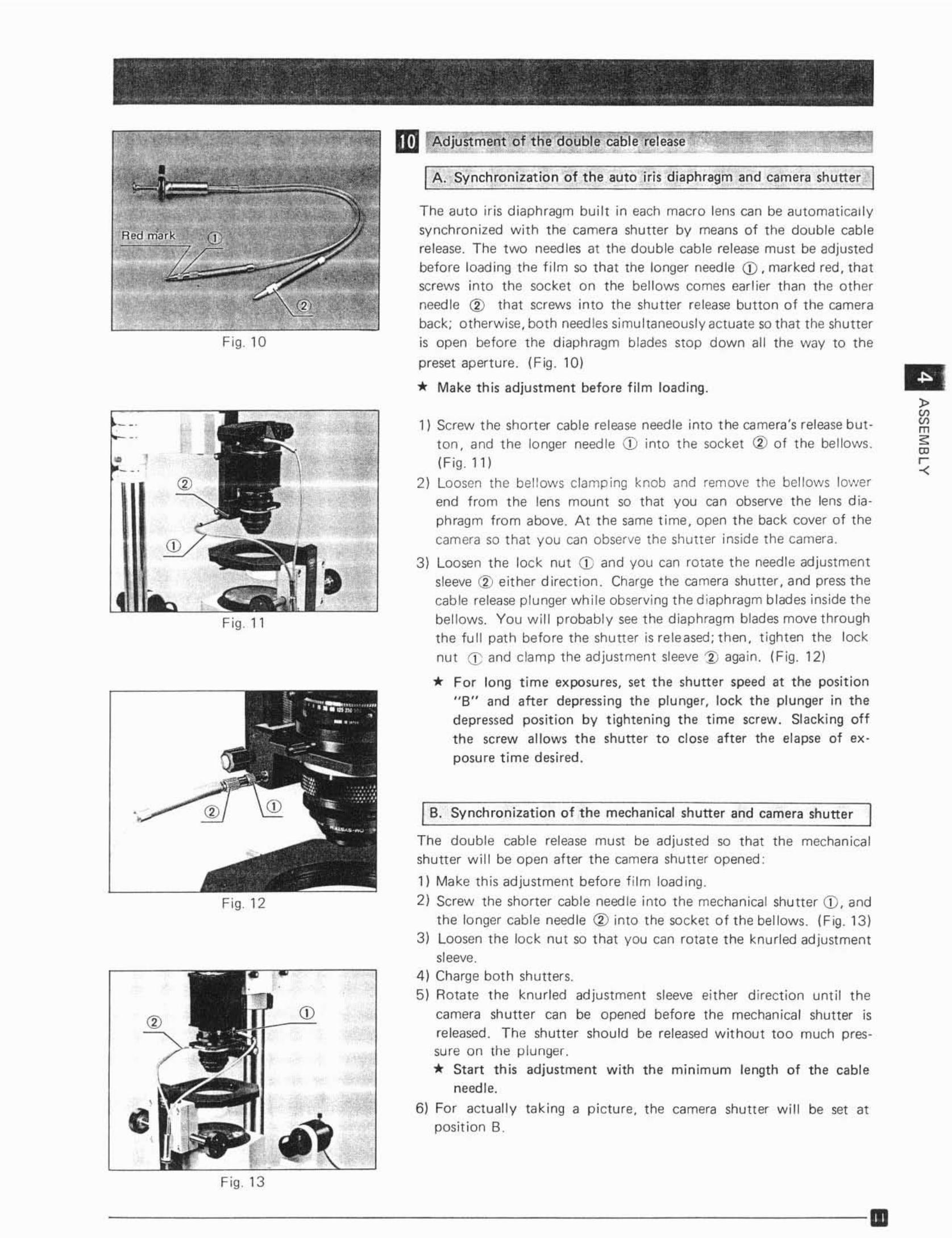
A . Synchronization of the auto ir is diaphragm and camera shutt er
The auto iris diaphragm bui lt in each macro lens can be automaticallysynchronized with t he camera shutter by means o f t he double cablerelease. The two needles at the double cable release must be adjustedbefore loading the fi lm so that the longer needle CD . marked red, thatscrews into the soc ket on the bellows comes ear lier than the o therneedle <V that screws into the shutter release button of the cameraback; otherwise , both needles simultaneously actuate so that t he shutteris open before t he diaphraqrn blades stop down all the way to the
pr eset aperture. (Fig. 10)
* Make this adjustment before film loading.
1) Screw the shorter cable release needle into the camera's release but ton, and the longer need le CD into the socket <V of t he bellows.(F ig. 11 )
2} Loosen the bellows damping knob and rem ove the bellows IO'Nerend from t he lens mount so that you can observe the lens diaphragm from abo ve . At the same time, open the back cover of thecamera so that you can observe the shutter inside the camera.
3) Loose n the lock nut CD and you can rotate t he needle adju stmentsleeve (2) eit her direct ion. Charge t he camera shutter , and press t hecab le release p lunger whi le observing the diaphragm blades inside t hebellows. You will probably see t he diaphragm blades move t hroughthe fu ll path befo re the shu tter is released; then, ti ghten t he lock
nut CD and clamp the adjustment sleeve i) aga in. (Fig , 12)
* For long t ime exposures, set t he shutter speed at the position"B" and after depressing the plu nger, lock the plunger in thedepressed position by t ightening t he t ime screw. Sl acking offthe screw allows the shutter to close after the elapse of ex posure time desir ed .
B. Synchronizat ion of the mechanical shutter and camera shutter
The double cable release must be adjusted so that the mechanicalshutter will be open alter the camera shutter opened :
1) Make thi s adjustment before film loading.
2} Screw the shorter cable need le into the mechanical shu tt er CD, andthe longer cable needle <V into the socket of the bellows. (Fig.1 3)
3) Loosen the lock nut so t hat you can rotate the knurled adjustmentsleeve.
4 ) Charge both shutters.5) Rotate the knurled ad ju stment sleeve either d irection until the
camera sh utter can be opened befo re the mechanica l shutter isreleased. The shutter should be released w ithout too much pressure on the plunger.* Start this adjustment w ith the minimum length of t he cable
needle.
6) For actually taking a pi ctu re, the camera shutt er w i ll be set atposition B.
J>l:lm
"~r-<
--- --------- - - - ---- --- m
EI
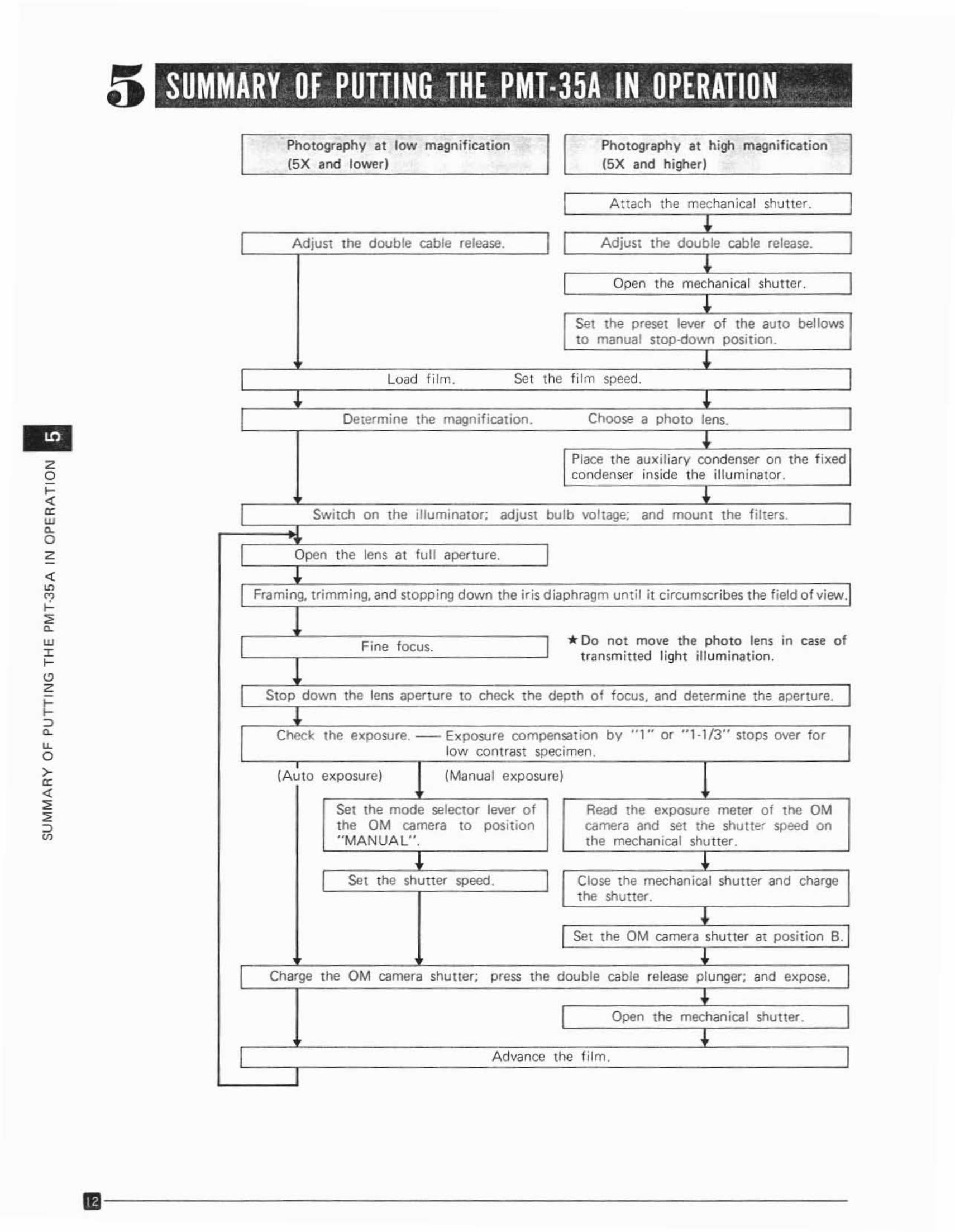
SUMMARY OF PUlTINGJHE PMl·35A IN..OPERATION. - . . -. . . - . ,- ~ .. '- _. .
Photography at low magnification Photography at high magnification(5X and lower) (5X and higher )
I A ttach the mechanical shutter . I~
I A djust the doub le cable release. I I Adjust the double cable release. I!
I Open the mechanical shutter. I~
Set the preset lever of the auto bellowsto manua l Slop-down position.
~
I Load f ilm . Set the fi lm speed. I! ~
I Determine the magnif icat ion . Choose a photo lens. I!
Place the auxil iary condenser on the f ixedcondenser inside the illum inator .
~
I Switch on the illuminator; adj ust bulb vo ltage; and mount the f ilters. I
I Open the lens at ful l aper ture. I!
I Framing, trimming, and slopp ing down the iris d iaphragm until it ci rcumscribes t he f ield of view.I
I Fine focu s. I * Do not mo ve the photo lens ,n case oft ransm itted li ght illumination .
I Stop down the lens aperture to check t he depth of focus, and determine the aper ture. I~
Chock the exposure. Exposure co mpensat ion by " 1" or " 1-113" stops over fo rlow contrast specimen.
(A uto exposure) (Manual exposure)
Set the mode selector lever o f Read the exposure meter of the OMtne OM camera to posit io n camera and set tne shutter speed on" MA NUA L". the mechanical shutter .
! !I Set the shutter speed . I Clo se the mechanical shutter and charge
the shutter.
~
I Set the OM camera shutter at posit ion B.I!
I Charge the OM camera shutter; press the double cable release plunger; and expose.
~
I Open the mechanical shutter . I~
I Advance 'ho f ilm . I
1IiI - - - - - - - - - - - - - - - - - - - - - -
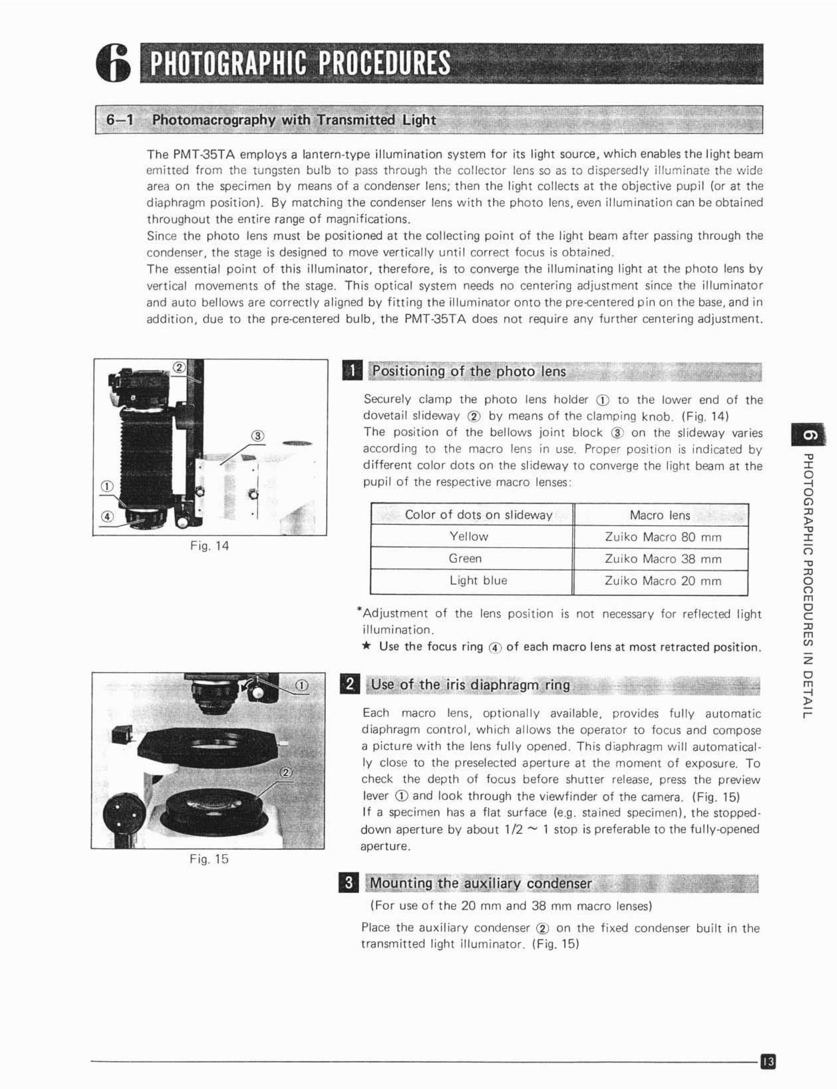
6 PHOTOGRAPHIC PROCEDURES ., - '.' . " . . .J. . .; , .~~_ '_.J~" ".' _ "',
6-1 Photomacrography with Transmitted Light
The PMT.J5TA employs a tentem-tvoe illumination system for its li ght source, which enables t he light beamemitted from the tungsten bulb to pass through t he collec tor lens so as to dispersedly illum inate the widearea on the specimen by means of a condense r lens; t hen the !igh l collects at the objective pup i l (or at thed iaphragm posi tion). By matching the condenser lens w ith the pho to lens, even ill um ination can be obtainedthroughout the entire range of magnifications.Since the photo lens must be posit ioned at t he collecting point of the light beam after passing t hrough thecondenser , the stage is designed to move vertically unti l co rrect focus is ob tained.The essential point of this illuminator, t herefore, is to converge t he illum inating light at the photo lens byvert ical movements of the stage. This opt ical system needs no center ing adjust ment since t he illuminato rand auto bellows are correct ly al igned by filt ing the illuminator onto the pre-cen te red p in on t he base, and Inaddit ion, due to the pre-centered bu lb, t he PMT-35TA does not require any fu rther centering adjustment.
-c
'"":)o"'""-c'"o-c.no"moC
'"m~
zem
i!r-
,
Color o f dots on slideway Macro lens
Yellow Zuiko Macro 80 mm
Green Zu iko Macro 38 mm
Light blu e Zu iko Macro 20 mm
Each macro lens, op tio nally available, prov ides fu ll y automat icdiaphragm control , wh ich al lows the operator to focus and composea pictu re with t he lens full y opened . Th is d iaphragm w ill autornatical
ly clo se to the preselected aperture at the moment of exposure. Tocheck the depth of focus before shutter release, press the preview
lever CD and look through the viewfinder of the camera. (Fig. 15)If a specimen has a flat surface (e ,g . stained specimen), t he stopped down aperture by about 1/2 ...... 1 stop is preferable to the fully-openedaperture.
*Adjust ment of the lens posit ion IS not necessa ry for ref lected lighti llum ination.
* Use the focus r ing (4) o f each macro lens at most retracted posit ion .
D pOfifjo ning of die p.:tiO!O lens
Securely clamp t he photo lens holder CD to the lower end of thedoveta il slideway (2) by means of the clamp ing knob. (Fig. 14)The posit ion of the bellows jo int b lock (j) on the sl ideway variesaccord ing to the macro lens in use, Proper posit ion is ind icated bydifferent co lor dots on the sl ideway to converge the light bea m at t hepupi l o f the respective macro lenses:
fJ Use of t he iris dlap'hragm ring
II MounttQ9 the ~uxi liary c~on~lla~e!!!n~s~!or::===~=:::=:::(For use o f t he 20 mm and 38 mm macro lenses)
Place the auxil iary condenser CV on the f ixed condenser bu ilt in thetransmitted light il lum inator. (Fig. 15)
,
(j)
Fig, 15
....~....-
F ig. 14
- - ----------------- ----- 11]
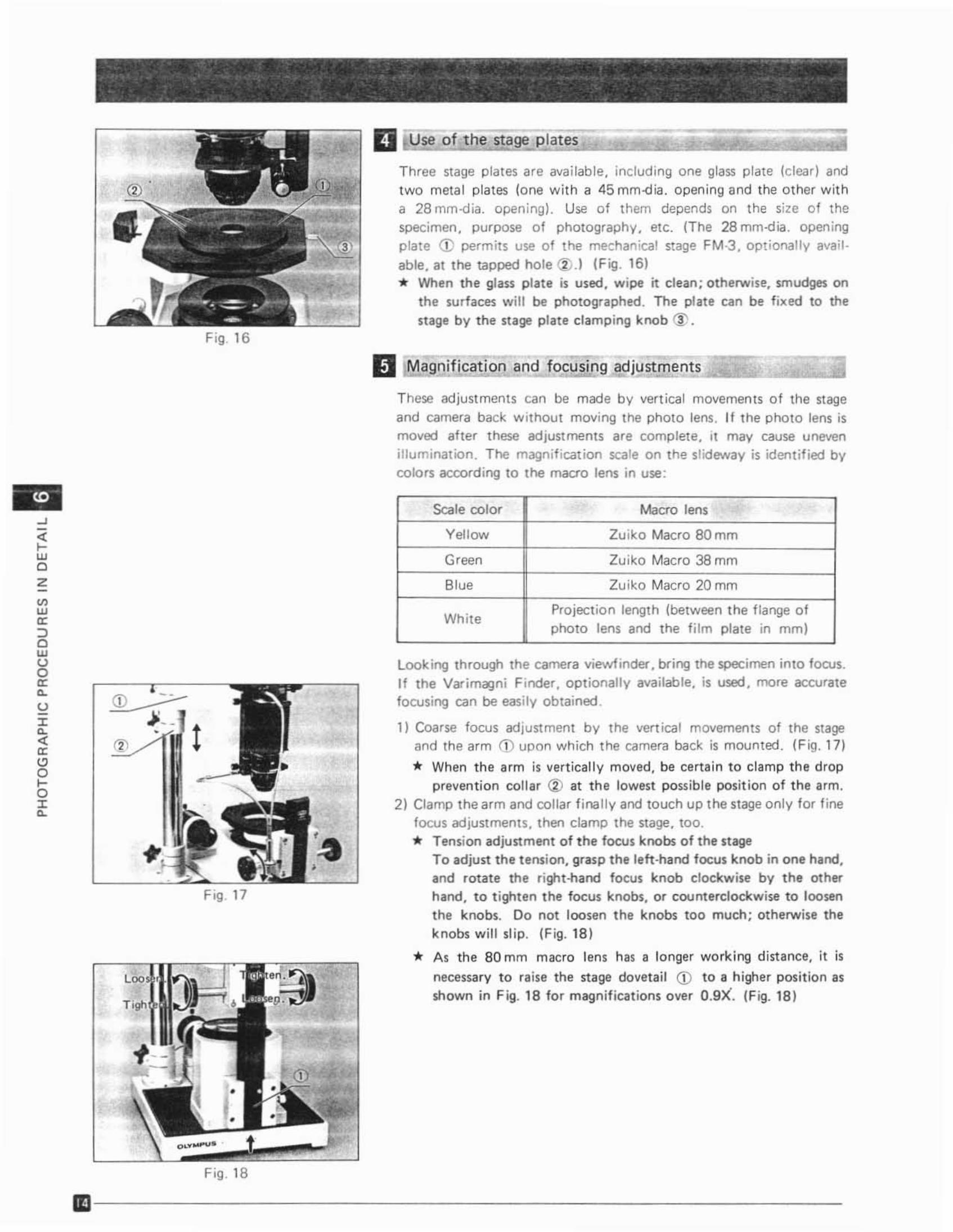
--o Use of the sta~ p'lates
Three stage plates are ava il able, including one glass p late (clear) andtwo metal plates (one w ith a 45 mrn-dia . opening and the other w itha 28 mm-dia . opening). Use of t hem depends on the size of thespecimen, purpose o f photography . etc. (The 28 mrn-d ia. open ingp late CD permits use o f the mechan ical stage FM·3 . opt ionally available . at the tapped ho le (j).1 (Fig . 16)* When the glass plate is used, wipe it clean; otherwise. smudges on
the surfaces will be photographed . The plate can be fixed to thestage by the stage plate cla m ping knob {j' .
II Magnificat ion and focusing adju~st[i]m~e~n~t~s":==:"_'::'.:JThese adjustments can be made by vertical movements of the stageand camera back w ithout mov ing the photo lens. If t he photo lens ismoved after these adjust ments are compl ete. It may cause unevenillumination. The magn if ication scale on the slideway is ident ified bycolors according to the macro lens in use:
~
jOwczV>w'"OJcws'"e,
u:re,
"o:ogo:rc,
Fig , 17
Fig, 18
Scale color Macro lens
Yellow Zu iko Macro 80 mm
Green Zu iko Macro 38 mm
Blue Zu tko Macro 20 mm
WhiteProject ion length (between the f lange o fphoto lens and the fi lm plate in mm)
Look ing through the camera viewfinder, bring the specimen into focus.If the Var imagni Finder , optionally availab le. is used , more accuratefocusing can be easi ly obtained.
1) Coarse focus adjustment by the vertical movements of the stageand the arm (j) upon which the camera back is mounted. (F ig. 17)
* When t he arm is vertically moved, be certai n to clamp t he dropprevention collar CV at the lowest possib le position of t he arm.
2) Clamp the arm and collar f inally and touch up the stage only for f inefocus adjustments, then clamp the stage , too.* Tension adjustment of the focus knobs of the stage
To adjust the t ension, grasp the left-hand focus kn ob in one hand,and rotate the right -hand focus kn ob clockwise by the otherhand, to t ighten t he focus knobs, or counterclockwise to loo senthe knobs. Do not loosen the knobs too much; otherwise thek nobs will slip. (Fig. 18 )
* A s t he 80 mm macro lens has a longer wo rking d istance, it is
necessary to raise the stage dovetail CD to a h igher posit ion asshown in F ig. 18 for magnif icat ions over O.9X·. (Fig. 18 )
III - - - - - - - - - - - - - - - - - - - - - - - -
~ • • ft •
. ,~ . , .... -'-: '
CD
Fig. 19
'.,.~• •
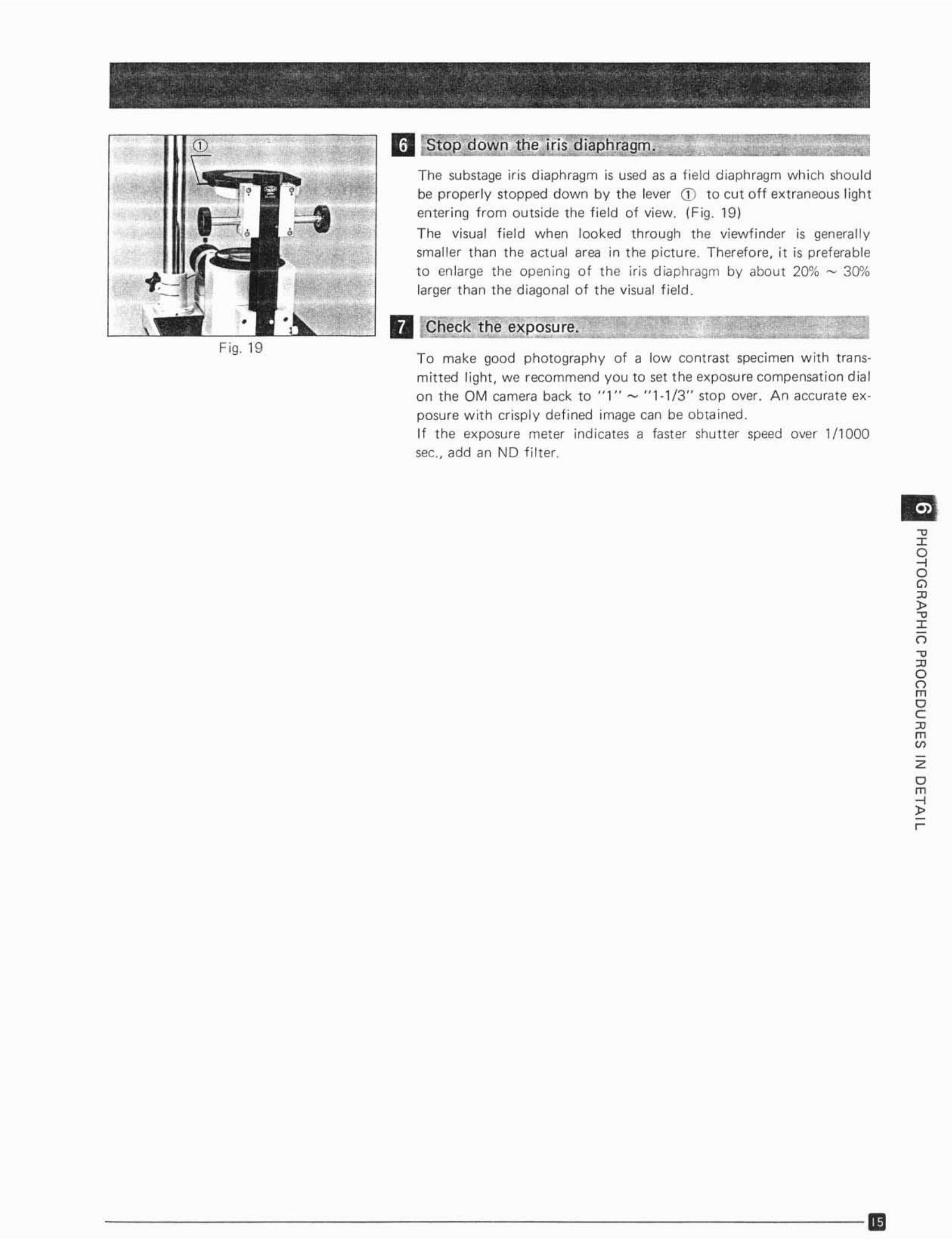
The substage ir is d iaphragm is used as a fie ld d iaphragm which shou ldbe properly stopped down by the lever CD to cut off extraneous l ightentering from outside the f ield of view. (Fig. 19)
The visual f ield when looked th rough the viewfinder is generallysmaller t han the actual area in t he pictu re. Therefore , it is preferableto enlarge the open ing of the iris d iaphragm by about 20% - 30"10larger t han the diagonal of the visual f ield .
Q t"Q:hec the exposure,
To make good ph otography of a low contrast specimen w it h transmitt ed light, we recommend you to set t he expo su re compensation dialon the OM camera back to "1 " ...... " 1·1 / 3 " stop over. An accurate exposure w ith crispl y defi ned image can be obtained.If t he exposure met er ind icates a faster shutter speed over 1/1000sec.. add an NO filter.
-e:l:
So"""-e:l:o-c
"oomoC
"monzom
i!r-
- - - - - - - - - --- - - - -------11:'1
J
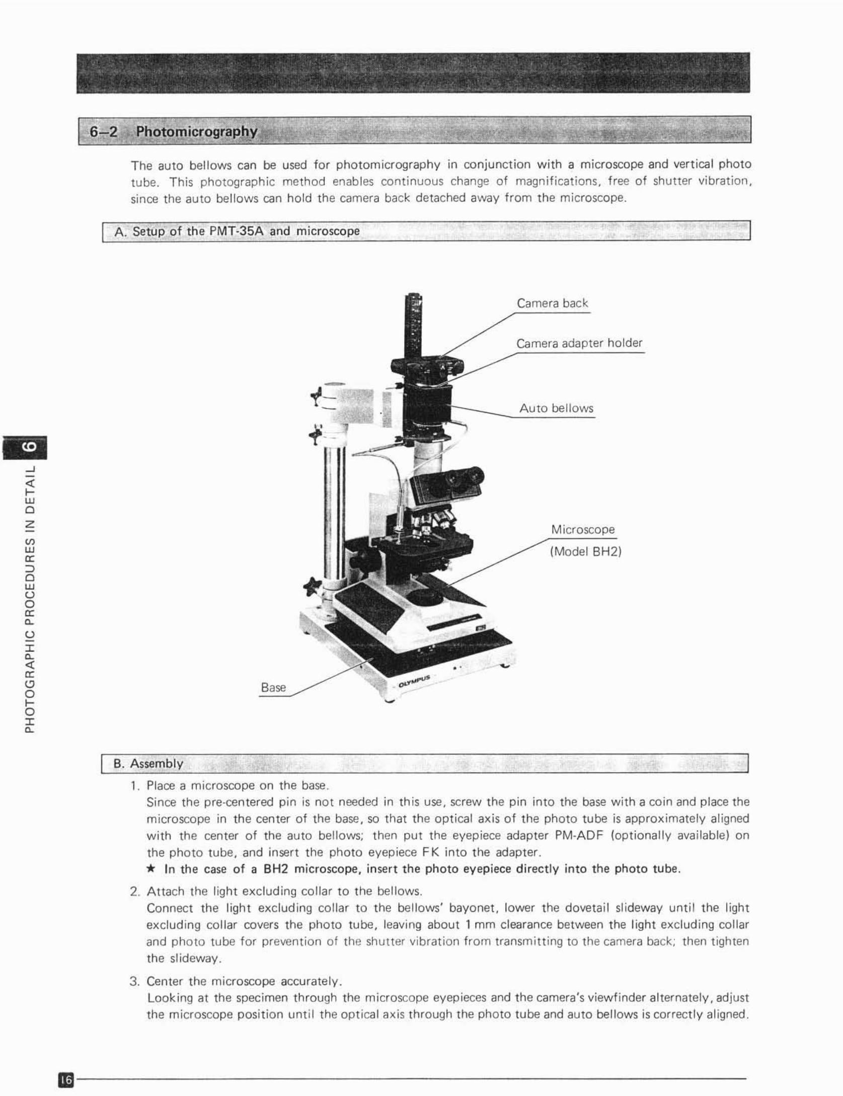
The auto bell ows can be used for photomicrography in conjunction w ith a microscope and vert ica l phototube. This photographic method enables continuous change of magnifications, f ree of shutter vibration,
since the auto bellows can hold the camera back detached away from the microscope.
A. Setup of the PMT-35A and microscope
Microscope
(Model BH2)
Auto bellows
Camera back
Camera adapter holder
~
;':waZ
I B. Assembly
1. Place a microscope on the base.Since the pre-centered pin is not needed In this use, screw the pin into the base with a coin and place themicroscope in the center of the base, so that the optical axis of the photo tube is approximately alignedwith the center of the auto bellows; then put the eyepiece adapter PM·AD F (optionally available) on
the photo tube, and insert the photo eyepiece FK into t he adapter.* In the case of a BH2 microscope. insert the pho to eyep iece d irect ly into the photo tu be.
2. Attach the light excluding collar to the bellows.Connect the light exclud ing collar to the bellows' bayonet, lower the dovetail slideway until the light
exclud ing collar covers the photo tube. leaving about 1 mm clearance between the light excluding collarand photo tube for prevention of the shutter Vibration from transmitt ing to the camera back; then tighten
the slideway,
3. Center t he microscope accurately .Looking at the specimen through the microscope eyepieces and the camera's viewfinder alternately. adjustthe microscope position unti l t he optical axis through the photo tube and auto bellows is correctly aligned.
1Iil - - - - - - - - - - - - - - - - ----- - - -
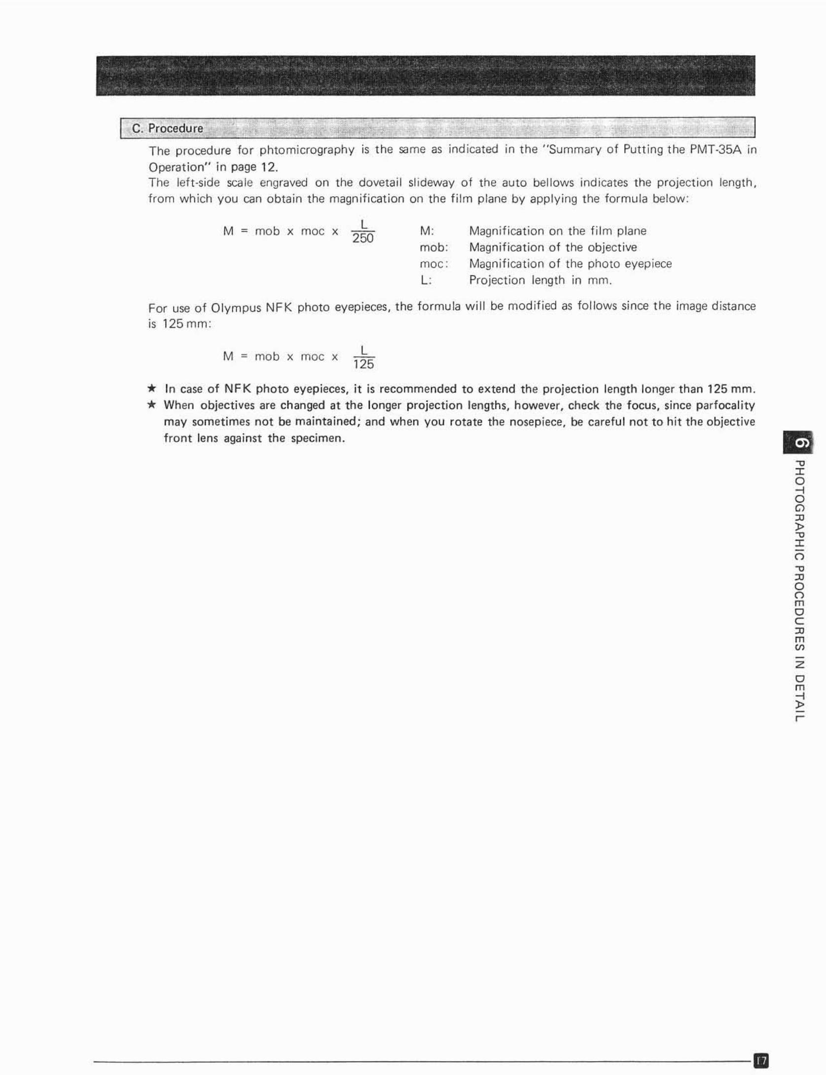
C. Procedure
The procedure for phtomicrography is the sa me as indicated in the " Summary of Put t ing t he PMT-35A in
Operat ion" in page 12.The lett-side scale engraved on the dovetail slideway o f the auto bellows indicates t he proj ection length,from wh ich you can obtain the magnifi cation on the f ilm p lane by app ly ing the formu la below:
M= mob x moc x L250
M,mob:moc:
L'
Magnif ication on the f ilm planeMag nif icat ion o f the objecti veMag nif icat ion of the photo eyep ieceProject ion length in mm.
For use o f Ol y mpus NFK photo eyepieces, t he formula w i ll be mod ified as follows since the image distance
is 125 mm:
M = mob x moc x L125
* In case of NF K photo eyepieces, it is recommended to extend t he project ion length longer than 125 mm.* When object ives are changed at the longer project ion lengths, however, check the focus, since parfocalitv
may somet imes not be maintained; and when you rotate the nosepiece, be careful not to h it the objectivef ron t lens against the specimen.
- - ----- ---------------Iil
-e
'"o-<oo~,.-c
'"o-cznoomoc;
'"m'"Z
om:;!r-
6-3 Photomacrography with Reflected Ught
Ref lected l ight can be employed in a w ide range of photomacrographi c appl ications. depending upon thevarious forms and conditions of specimens or photographi c purposes. Some of the typical applicat ions ofthis photomacrograph ic equipment (pMT·35AAl. includ ing sta ndard or optional components, will be explained as follows:
D e "llummation
•
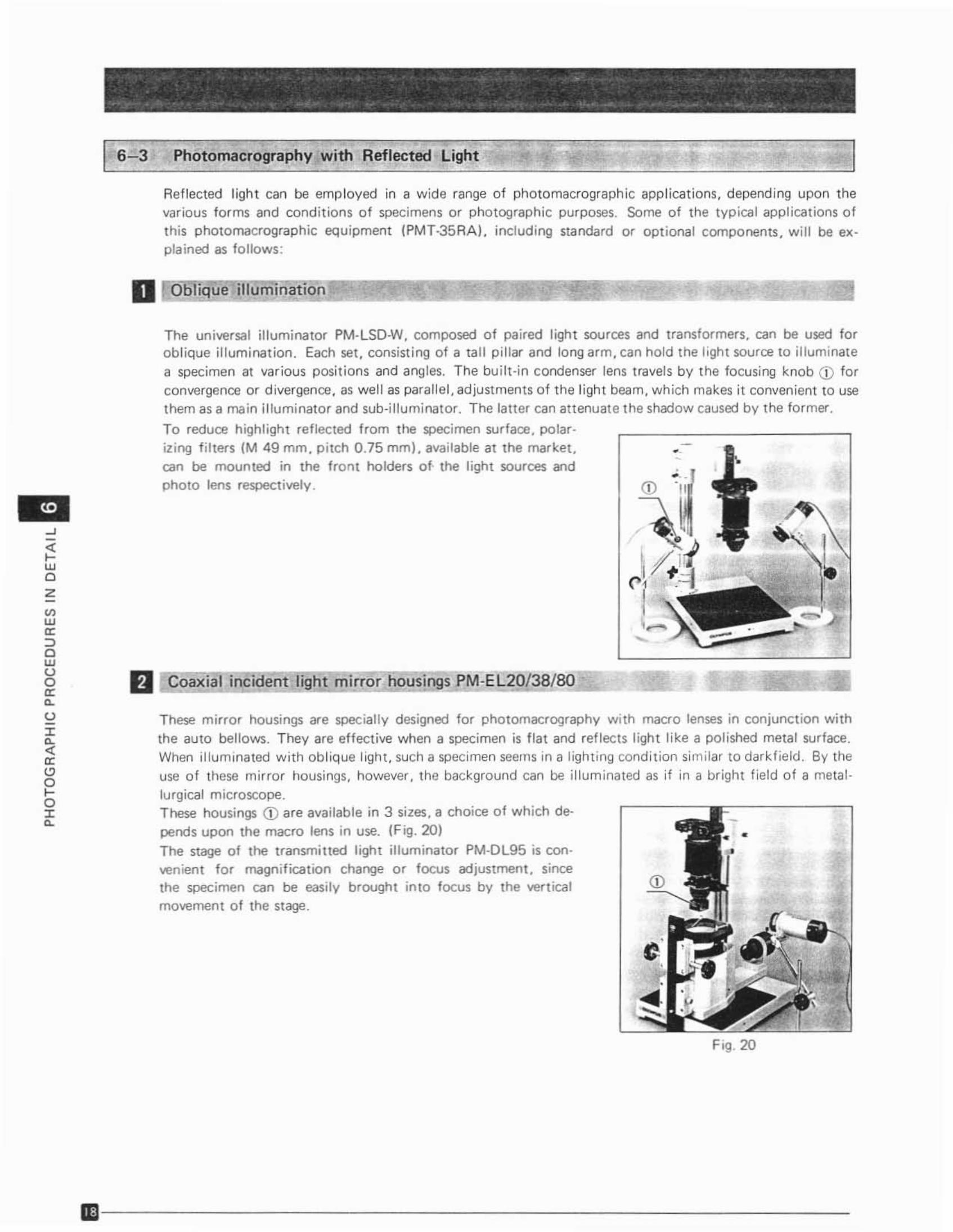
The universal il luminator PM-LSD-W. composed of paired ligh t sources and transformers, can be used foroblique illumination . Each set, consisting of a tall pillar and long arm, can hold the l ight source to illuminate
a specimen at var ious posit ions and angles. The bui lt -in condenser lens travels by the focusing knob CD forcon vergence or d ivergence, as well as parallel , adjustments of t he l ight beam, which makes it convenient to usethem as a main illuminator and sub-illuminat or. The latter can attenuate the shadow caused by t he former,
To reduce highl ight ref lected from the specimen surface , cotar.izing f ilters (M 49 mm, pitch 0 .75 mml, available at the market ,can be mounted in the front holders o f. the light sources andphoto lens respect ively .
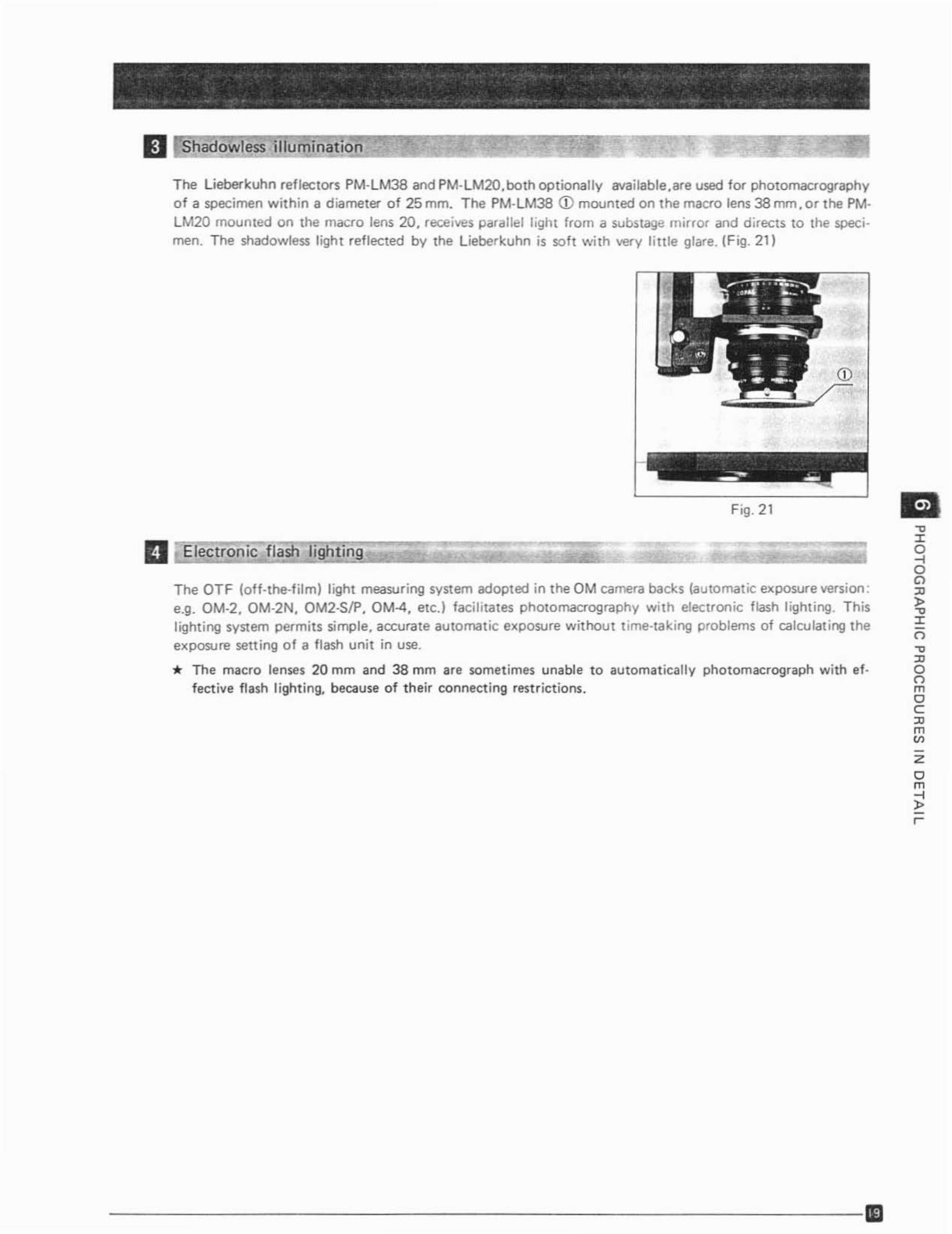
These mirror housi ngs are spec ially designed for photomacrography w ith macro lenses in conjunction with
the auto bellows . They are effect ive when a specimen is f lat and reflect s l ight li ke a polished metal surface .When illuminated w ith obl ique light , such a specimen seems in a light ing condition sim ilar to darkf ield . By theuse of these mi rror housings, however , the background can be illuminated as if in a bright f ield of a metallurgical microscope.Trese housings CD are available in 3 sizes, a choice o f wh ich de
pends upon the macro lens in use. (Fig . 20)
The stage of the transmitted light illuminator PM-DL95 is convenient for magnifica tion change or focus adjustment , sincethe specimen can be easily brought in to focus by the vertical _(j),"",~movement o f the stage.
D oaxlal incuJent ignt mirror nousioos PM-E L20/38/BO...._
....-;;wcz
'"w<r::>owoo<re,
oJ:e,
'"<rcoloJ:e,
Fig. 20
ID- - - - - - - - - - - - - - - - - - - - - -
D Sflaoowless iIIummation
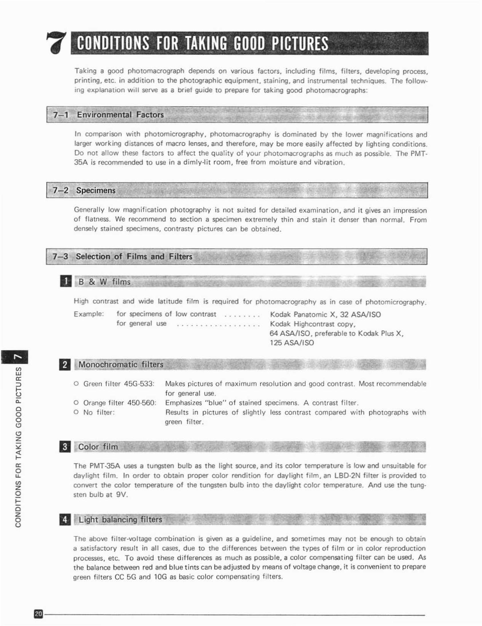
The Lleberkubn ref lectors PM-LM38 and PM -LM20.both op t iona lly eveuebte.are used for photomacrographyo f a specimen with in a diameter of 25 mm. T he PM·LM38 Q) mounted on the macro lens 38 rrvn.c r the PM·LM 20 mounted on the macro lens 20. receives paralle l light from a substagoa mirror and directs to the sceclmen. The shadcwless l ight reflected by the Lieberku hn is soft with very l ittle glare. IFig. 21)
Fig.21
II Electronic f1aSti lignting
The OTF {ott-tne -fltm) light measur ing system adopted in the OM camera backs (automatic exposure version ;e.q. OM·2. OM-2N. OM2-SIP. OM-4, etc.} faci htates photomacrography with electronic flash lighting. Thisl ighting system permits simple. accurate automatic exp osure w it hou t t ime·tak ing problems of calcu lating t he
exposure setting of a f lash unit in use.
* The macro lenses 20 mm and 38 mm are sometimes unable to automat ically photomacrograph with ef ·fect lve f lash li ght ing. because of their connect ing restr ict ions.
- --- ------ - ----- - - - - --ID
-c:z:8o<l
"~:z:o~
"gmoC
"m~
zom~r-
7 CONDITIONS FOR TAKING GOOD PICTURES• •• • •
Taking a good phc tc macroqraph depends on var ious factors . including f ilms, f ilters, developing process,printing, etc. in add it ion to the pho tograph ic equ ipment. staining, and instrumen tal techniques. The fo llowing explana tion w il l serve as a br ief guide to prepare for taking good pho tomacrog raphs :
In co mparison w ith photomicrography. pho tomacrography is dominated by the lower magn ifications andlarger work ing d istances o f macro lenses, and therefore, may be more easi ly affected by l ight ing conditions.Do not all ow th ese factors to affect the qual ity of your cnotomecrccraobs as much as possible. The PMT35A is recommended to use in a dimly-l it r oom . free from moisture and vibration .
I7-2 Specimens. "
•
Generall y low magn if icat ion photography is not suited for detailed examination , and it gives an impressiono f fla tness. We recom mend to section a specimen extremely thin and stain it denser than normal. Fromdensely stained specimens, con rrastv pictures can be obtained.
7-3 Selection of Films and Filtersl' = I
D [Li9fE!~~==========::J
Makes pictures o f maximum reso lu tion and good con trast . Most recommendablefor general use.Emphasizes "blue" o f stained specimens. A contrast f ilter .Results in p ictures of Sligh tly less cont rast compared with photographs withgreen fi lter .
o Green fi lter 45G·533:
o Orange filter 450·560:o No f ilter :
H igh contrast and w ide latitude f ilm is required for pho tomacrography as in case of photomicr ography .
Example: for specimens of low contrast Kodak Panato rmc X, 32 A SA!ISOfor general use Kodak Hiqhccmrast co py,
64 ASA/I SO, preferable to Kodak Plus X,125 ASA/ ISO
The PMT-35A uses a tungsten bulb as the light source, and its color temperature is low and unsuitable fo r
dayl ight film. In order to obtain proper color rendit ion for daylight fi lm , an l BO·2N fiher is provided toco nvert the co lor temperatu re o f the tungsten bulb into the daylight co lor temperature. And use the tuoqsten bulb at 9V.
D Monochromatic f ilters
II Color f ilm
"'w
'"::>roe,
cooC>C>Z
'""a:ou,
"'zorczoo
-
The above tnter-vcnece combinat ion is given as a guideline. and sometimes may not be enough to obtaina satisfactory resu lt in all cases. due to the d ifferences between the types of film or in co lor reproductionprocesses. etc. To avoid these d ifferences as much as possible. a co lor compensa ting f ilter can be used. Asthe balance between red and blue t ints can be adjusted by means of voltage change. it is convenient to prepare
green filters CC 5G and 10G as basic color compensating f ilters.
Bil- - - - - - - - - - - - - - --- - - - - -
II Neutra aenslty. fi ters
It is necessary to reduce l ight intensity when illuminat ion is too bright , especially when the transmittedlight illuminator is used in low magnification . To avoi d voltage change wh ich affects color rendition , NOfilters are preferable .
u : = " ' ,, _.
Color reversal fil m is suited to obtain color slides or transparencies; whi le color negat ive is used for duplicatecolor prints. When printing co lor dupli cates f rom negative f ilm the processing laboratory has wider lat itudein reproducing co lor tones t han w ith reversal fi lm. The laboratory automaticall y adjusts color reproductionwhen pr inting famil iar objects as landscapes, portraits, etc.When processing ohotomrcro or photomacrographic prints, however, the laboratory has no exper ience togu ide them; and we therefore suggest a photomacrographer to si multaneously photograph the specimen ona color reversa l exposed under identical condi t ions (including ident ica l or suitably adjusted color temperature). and supply the labora tory wi th a transparency to guide them in t he selection of the correct co lo rhues of the print . Or it is also advisable to d irect ly pr int from the reversal.
- - ---------------- --- --f.D
8zo
'"oz~
-no">!"z""ooo-c
~"m~
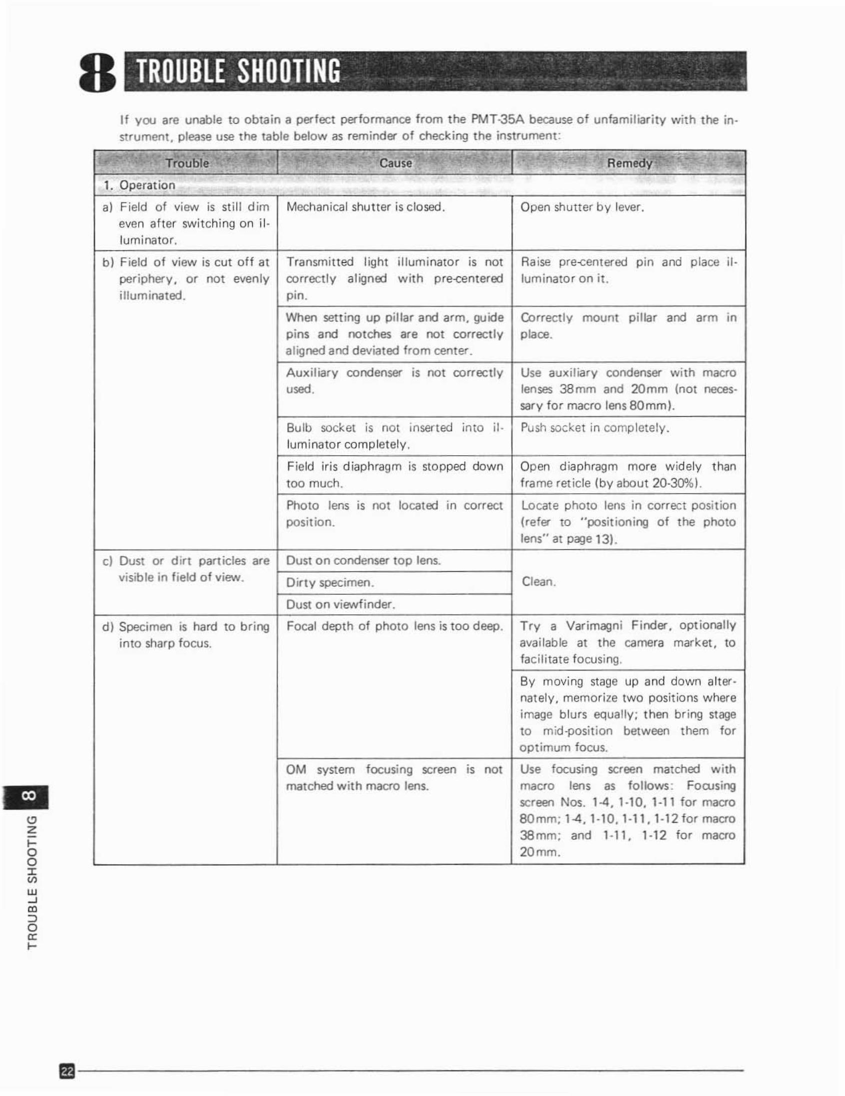
8 TROUBLE SHOOTING . ... .. ..If you are unable to obta in a perfect performance from t he PMT·35A because o f unfami liar ity with the instrument . please use t he table below as rem ind er of checking t he instrument :
oZIoo;:;w~
'"::>o'"I-
T~·~ub le, C.' .. .., ... . .. ..
R .m'dY"''' '~''.. Cause ' .1. Operat ion
a) Field of view is still dim Mechanica l shutter is clo sed . Open shutter by lever.even after switching on il -lum inator.
b] Field o f view is cut off at Transmitted light illuminator rs not Raise pre-centered pin and place il-pe riphery. 0' not evenly correctly a ligned w it h p re-centered luminato r on it.
illum inated . pm.
When sett ing up pillar and arm, guide Correct ly mount pilla r and aIm inpins a nd notches ate not correct ly place.a ligned a nd deviated from center.
Auxiliary condenser is not correctly Use 3UJdliary condenser with macro
" sed, lenses 38mm and 20mm Inot reces-sarv for macro lens BOmml.
Bulb socket rs not inserted into iI· Push socket in complete ly.lum inato r completely .
Field iris d iaphragm is stopped down Open diaphragm more w idely than
too much. f rame ret ide (by about 20-30%).
Photo lens rs not locat ed In correct Locate photo lens in correct posit ionposition. (refer to "positioning o f t he photo
lens" at peqe 13).
c) Dust or d irt part id es ate Dust on condenser top lens.
visible in f ield o f view. D irty specimen . Clean.
Oust on viewfinder.
d) Specimen is hard to br ing Focal depth of photo lens is too deep. T I Y a Var imagni Finder, optionall y
into sharp focus. available at the camera market , tofac ilitate focusing.
By moving stage up and down alter-natelv, memor ize two posit ions whereimage blurs equally ; then bring stageto rnld -posl tion between them toroptimum focu s.
OM svstem focusing screen rs not U,. focusing screen matched withmatched w ith macro lens. macro Ierts as follows : Focusing
screen Nos. 1-4, 1-1 0 , 1-1 1 for macro8Omm; 14, 1-1 0, 1-11, 1-12 for macro
38mm; and 1-11 , 1-12 tor macro
20mm.
" • - . ; " < - cause , . L~ - I"''''fi '' , . " Remedy',
Trouble ,, ,
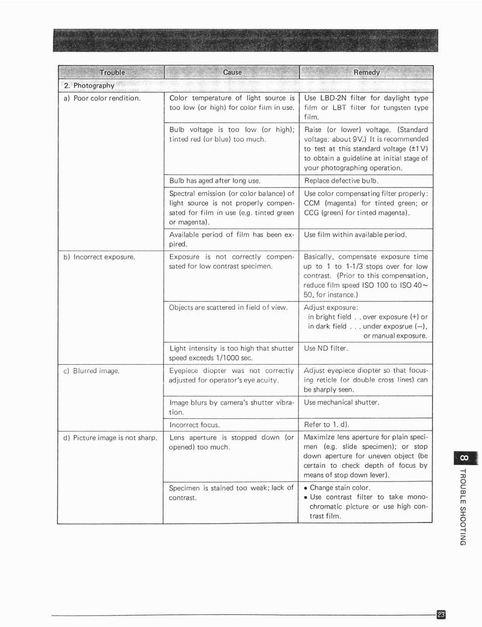
2, Photography
,} Poor color rend it ion. Colo r temperature of light source is Use LBD-2N filter for daylight typetoo low (or high) fo r co lo r f ilm in use. f ilm or LBT f il ter for tungsten type
f ilm.
Bu lb voltage rs too low (0' high); Ra ise (0' lower) vol tage. (Standa rdt inted red (or blue) too much . vo ltage: abou t 9V.l It is recommended
to test at this standard voltage (±1 V)to obta in a guideline at initia l stage ofyour photographing opera tion.
Bulb has aged after long use, Replace defect ive bu lb.
Spectra l emission (or co lor balance) of Use color compensating fi lt er properly:light source is not proper ly cc rnpen- CCM (magenta) fo r tinted green; 0'sated fo r fi lm in use (e.g . t inted green CCG (gre en) f or t inted magenta).or magenta} .
Ava ilab le per iod of fil m has been ex- Use fi lm w ithin availab le per iod.
pired.
b ) Incorrect expo sure. Exposu re rs not co rrectly comoen. Basically , compensate exposure t imesated for low contrast specimen. up to 1 to 1·1/3 stops over for low
contrast . (Prior to this compensat ion,
reduce fi lm speed ISO 100 to ISO 40-50, for instance.)
Obj ects are scattered in fie ld o f view. Adjust exposure:in br ight f ield . . over exposure {+} orin dark fie ld . . . under exposrue (-J.
or manual exposure.
Light intensity is too high t hat shutter Use ND filt er .
speed exceeds 1/1000 sec.
cl B lurred i rn a~e . Eyep iece d iopter w", em correctl y A djust eyep iece d iopter so tha t tocus-
adjust ed for operato r's eye acu ity _ ing reticle (o r doub le cross lines] canbe sharp ly seen.
Image b lurs by camera's shutter vib ra- Use mechanical shutter .t fon.
Incorrect focus Refer to 1. d).
d) Pi ctu re image is not sharp . Lens aperture rs stopped down (0 ' Maxim ize lens apertu re for plai n specl-
opened) too much. moe (e.g. slide specimen); 0' stopdown aperture for uneven object (becerta in to check depth of focus bymeans of stop down lever).
Specimen is sta ined too weak; lack of • Change stain color .
con trast . • Use contrast filter to take mono-
chromatic p icture or use high con-trast film .
--i
'"oC<Dem
"'Ioc::Zo

OLYMPUS OPTICAL CO. LTO. OLYMPLTS. S OKYO""':...SAN.E1 BUILDING, 22_2 . N ISHISHINJ UKU1.CHOME. SHIN JUKU.KU. TO KYO, JAPAN
Printed in J8Pl1n 8~08 M 03