pm-band-30 - Adaptive Technologies Group
1
PM-BAND-30 PoleStar ® Pole Banding Kits for 30” Bands Secure signs, mounts and other objects to round poles and columns using this band kit. The PM-Band-30 kit offers a pair of 30” long bands and tensioning hardware. They are designed for 4” to 6”/152mm pole diameters. The unique bolt kit requires only a socket wrench to secure and tension bands by hand. No special tools or equipment necessary. The 201 stainless band material is easy to work with, offers high strength, a clean appearance and good resistance to oxidation and weathering. These kits are great for both indoor and outdoor use. Custom lengths are available too. For marine applications, please ask our customer service for an alternative grade of stainless steel banding. SPECIFICATIONS: Material: Stainless Steel Finish: Silver WLL: 300 lb / 136 Kg single speaker *WLL = Working Load Limit Adaptive Technologies Group 1635 E. Burnett Street | Signal Hill, CA 90755 USA Ph: 562.424.1100 | Fax: 562.424.3520 www.adapttechgroup.com ALWAYS INSTALL SAFETY CABLES WARNING: Mounting and/or suspension of audio and video equipment requires experienced professionals. Improperly installed loudspeakers can result in property damage, personal injury and/or liability to the installing contractor. POLESTAR ® STANDARD FEATURES: Securely attaches items to poles and columns Model Length Width Max Dia WLL Weight PM-BAND-30 30”/76.2cm .75/19mm 6”/152mm 300 / 136kg 1.5 lb. /0.7 kg PM-BAND-90 90”/228.6mm .75/19mm 25”/635mm 300 / 136kg 2.5 lb. /1.1 kg Bevel Sliding retainer block 4”-6” Strap Fixed retainer block 6” carriage block PM-Series part Strap Fixed retainer block Sliding retainer block Pole or columns 4”- 6” Figure 2 Pole adapter Apply threadlock here Tighten nut Flat washer Pole or columns 1/2” Minimum
Transcript of pm-band-30 - Adaptive Technologies Group
PM-BAND-30
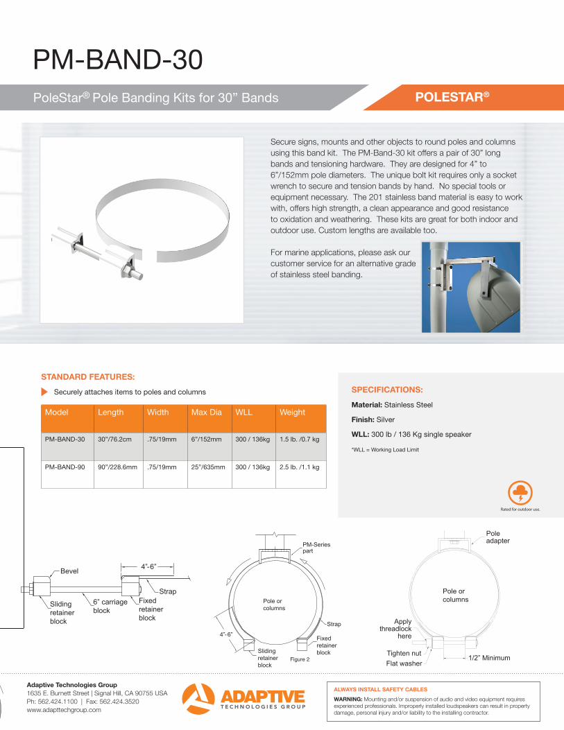
PoleStar® Pole Banding Kits for 30” Bands
Secure signs, mounts and other objects to round poles and columns using this band kit. The PM-Band-30 kit offers a pair of 30” long bands and tensioning hardware. They are designed for 4” to 6”/152mm pole diameters. The unique bolt kit requires only a socket wrench to secure and tension bands by hand. No special tools or equipment necessary. The 201 stainless band material is easy to work with, offers high strength, a clean appearance and good resistance to oxidation and weathering. These kits are great for both indoor and outdoor use. Custom lengths are available too.
For marine applications, please ask our customer service for an alternative grade of stainless steel banding.
SPECIFICATIONS:
Material: Stainless Steel
Finish: Silver
WLL: 300 lb / 136 Kg single speaker
*WLL = Working Load Limit
Adaptive Technologies Group1635 E. Burnett Street | Signal Hill, CA 90755 USAPh: 562.424.1100 | Fax: 562.424.3520www.adapttechgroup.com
ALWAYS INSTALL SAFETY CABLES
WARNING: Mounting and/or suspension of audio and video equipment requires experienced professionals. Improperly installed loudspeakers can result in property damage, personal injury and/or liability to the installing contractor.
POLESTAR®
STANDARD FEATURES:
Securely attaches items to poles and columns
Model Length Width Max Dia WLL Weight
PM-BAND-30 30”/76.2cm .75/19mm 6”/152mm 300 / 136kg 1.5 lb. /0.7 kg
PM-BAND-90 90”/228.6mm .75/19mm 25”/635mm 300 / 136kg 2.5 lb. /1.1 kg
This family of all-weather, load rated components provides a round strong foundation for mounting and aiming loudspeakers to poles and columns, both indoors and outdoors. The Polestar system is comprised of five components: a stainless steel support arm, pole adapters, a dual adapter and a choice of band kits and a safety anchor. Everything needed at the job site is available from stock. Starting with the popular load rated pole adapters, the following describes all the components that are available to complete your loud-speaker installation. For square poles see SAS-200-24-G.
INSTALLERS TAKE NOTE: Always secure mounted objects to the mounting structure with safety cables.
ALWAYS INSTALL SAFETY CABLESWARNING: Mounting and/or suspension loudspeakers requires experi-enced professionals. Improperly installed loudspeakers can result in prop-erty damage, personal injury and/or liability to the installing contractor.
Adaptive Technologies Group 1635 E. Burnett Street | Signal Hill, CA 90755 USAPh: 562.424.1100 | Fax: 562.424.3520www.adapttechgroup.com
POLESTAR® / MARINEALL-WEATHER POLE AND COLUMN MOUNTING SYSTEM
POLESTAR®
This type of installation assumes that the selected loudspeaker come with its own yoke style mounting arm. The installation then further requires a Support Arm, a Pole Adapter and a Band Kit. Each of these components is constructed of stainless steel material and come with the required assembly hardware. If a yoke arm is not supplied with the selected loudspeaker, contact us at:
This type of installation assumes that the pole is 6” in diameter or larger and the speakers come with their own yoke style mounting arms. This installation requires a dual adapter arm, the larger pole adapter and a band kit. When an adequate anchor point is not available, include the safety anchor. Each of these components are all-weather rated and come with the required assembly hardware. If a yoke arm is not supplied with the selected loudspeakers, contact us at:[email protected]
This type of installation assumes that the pole diameter is a 6” or larger and that the selected loudspeakers come with their own yoke style mounting arms. This installation requires a support arm, a dual adapter arm, the larger pole adapter and a band kit. When an adequate anchor point is not available, include the safety anchor. Each of these components are all-weather rated and come with the required assem-bly hardware. If a yoke arm is not supplied with the selected loudspeakers,contact us at [email protected]
SINGLE LOUDSPEAKER INSTALLATIONFOR 2-3/8”-6” POLES & LARGER
DUAL LOUDSPEAKER INSTALLATION FOR 6” DIAMETER POLES & LARGER
THREE LOUDSPEAKER INSTALLATION FOR 6” DIAMETER POLES & LARGER
Installation Guide PM-BAND-SERIESPoleStar Pole Banding Kit 30” - 90”
This all-weather, aluminum and stainless steel banding strap kit is designed toattach objects to indoor and outdoor poles and columns.
Contents:Be sure that all of the following items are included in this kit before proceeding:
2 pcs Banding straps 1 pc Fixed Bolt Retainer Block (30” or 90” long)1 pc Sliding Bolt Retainer Block 1 pc 3/8-16 x 6” Coated Carriage Bolt1 pc 3/8-16 Coated Flange Nut 2 pcs 3/8” Stainless Flat Washer1 pc Tube of thread lock 1 pc Instruction sheet
PM-BAND-30,-60-90
Bevel
Slidingretainerblock
4”-6”
StrapFixed retainer block
6” carriage block
PM-Series part
Strap
Fixed retainer blockSliding
retainer block
Pole or columns
4”-6”
Slidingretainerblock
Fixed retainer block
REV00-050720151 of 2
Installation GuidePoleStar Pole Banding Kit
This all-weather, aluminum and stainless steel banding strap kit is designed to attach objects to indoor and outdoor poles and columns.
Step 1: Assemble Fixed Retainer Block Mark the strap at least 4-6 inches from the end from the end and fold the strap at the mark. Strike the strap at the bend to create a sharp radius. Slide the strap through the Fixed Retainer Block so that its bend will pass over the beveled end of the block (Figure 1).Step 2: Assemble the Pole Adapter to the strap Insert the free end of the strap through the Pole Adapter’s slots, then through the Sliding Retainer Block, non-beveled end first (Figure 2).
Note to installersDue to the wide variety of wall structures, materials and mounting methods, these instructions assume that the installing contractor will exercise proper judgment in selecting the mounting area and hardware.As a guide, the installation, when complete should be capable of supporting 5 to 10 times the actual applied load. Also, always use a back up safety system such as a safety cable.To assure a trouble free installation, read through and follow these instructions carefully before beginning. If you have doubts about the integrity of the structure you are mounting to or you are not sure about the proper hardware to use, consult a structural and/or hardware specialist. Follow these instructions for the most efficient and safest mounting results. Do not exceed the working load limit of 300 lbs /136 kg.and always install safety cables.Be sure that all of the following items are included in this kit before proceeding:2 pcs Banding straps 1 pc Fixed Bolt Retainer Block (30”or 60” or 90” long) 1 pc Sliding Bolt Retainer Block 1 pc 3/8-16 x 6” Coated Carriage Bolt 1 pc 3/8-16 Coated Flange Nut 2 pcs 3/8” Stainless Flat Washer 1 pc Tube of thread lock 1 pc Instruction sheet
Figure 1
Figure 2
Figure 3
Installation Procedure:
Step 1: Assemble Fixed Retainer BlockMark the strap at least 4-6 inches from the end from the end and fold the strap at the mark. Strike the strap at the bend to create a sharp radius. Slide the strap through the Fixed Retainer Block so that its bend will pass over the beveled end of the block (Figure 1).
Step 2: Assemble the Pole Adapter to the strapInsert the free end of the strap through the Pole Adapter’s slots, then through the Sliding Retainer Block, non-beveled end fi rst (Figure 2).
Step 3: Determine Strap length for PoleHolding the Fixed Block fi rmly against the pole, overlap the strap. Move the Sliding Block up against the Fixed block so that their two beveled edges meeteach other (Figure 2).
PM-BAND-30,-60-90
Bevel
Slidingretainerblock
4”-6”
StrapFixed retainer block
6” carriage block
PM-Series part
Strap
Fixed retainer blockSliding
retainer block
Pole or columns
4”-6”
Slidingretainerblock
Fixed retainer block
REV00-050720151 of 2
Installation GuidePoleStar Pole Banding Kit
This all-weather, aluminum and stainless steel banding strap kit is designed to attach objects to indoor and outdoor poles and columns.
Step 1: Assemble Fixed Retainer Block Mark the strap at least 4-6 inches from the end from the end and fold the strap at the mark. Strike the strap at the bend to create a sharp radius. Slide the strap through the Fixed Retainer Block so that its bend will pass over the beveled end of the block (Figure 1).Step 2: Assemble the Pole Adapter to the strap Insert the free end of the strap through the Pole Adapter’s slots, then through the Sliding Retainer Block, non-beveled end first (Figure 2).
Note to installersDue to the wide variety of wall structures, materials and mounting methods, these instructions assume that the installing contractor will exercise proper judgment in selecting the mounting area and hardware.As a guide, the installation, when complete should be capable of supporting 5 to 10 times the actual applied load. Also, always use a back up safety system such as a safety cable.To assure a trouble free installation, read through and follow these instructions carefully before beginning. If you have doubts about the integrity of the structure you are mounting to or you are not sure about the proper hardware to use, consult a structural and/or hardware specialist. Follow these instructions for the most efficient and safest mounting results. Do not exceed the working load limit of 300 lbs /136 kg.and always install safety cables.Be sure that all of the following items are included in this kit before proceeding:2 pcs Banding straps 1 pc Fixed Bolt Retainer Block (30”or 60” or 90” long) 1 pc Sliding Bolt Retainer Block 1 pc 3/8-16 x 6” Coated Carriage Bolt 1 pc 3/8-16 Coated Flange Nut 2 pcs 3/8” Stainless Flat Washer 1 pc Tube of thread lock 1 pc Instruction sheet
Figure 1
Figure 2
Figure 3
Figure 1
Figure 2
Adaptive Technologies Group1635 E. Burnett Street | Signal Hill, CA 90755 USAPh: 562.424.1100 | Fax: 562.424.3520www.adapttechgroup.com
ALWAYS INSTALL SAFETY CABLES
WARNING: Mounting and/or suspension of audio and video equipment requires experienced professionals. Improperly installed loudspeakers can result in property damage, personal injury and/or liability to the installing contractor.
Step 4: Move the Sliding Block back at least 1”-2” and fold the strap at the Sliding Block’s beveled end. Strike the bend to form a sharp radius. Trim away the excess strap material leaving 4” or more of left over material. A Longer tail length provides more effective locking. Feed any excess strap material through the Pole Adapter’s slots, if necessary (Figure 4).
Step 5: Bend the strap at both Retainer Blocks, near the non-beveled ends to allow the Carriage Bolt to easily pass through each of the Retainer Blocks (Figure 3 and 4).
Step 6: Place the strap assembly around the pole, at the fi nal mounting height and secure the Retaining Blocks with the Carriage Bolt, Flange Nut and Flat Washer. Be sure that the Pole Adapter is oriented into the right direction and with the bolt assembly on the opposite side of the Pole Adapters (Figure 2 and 4).
Step 7: Tighen the Carriage Bolt Assembly until all slack has been removed from the fully loaded assembly. retainer blocks must have a minimum of 1/2” gap after fully tightened. Do not overtighten (Figure 5).
Step 8: Apply thread lock to the threads around the nut Step 9: Repeat above procedures for next strap assembly.
Installation Guide
Note to installers:
Due to the wide variety of wall structures, materials and mounting methods, the installing contractor must exercise proper judgment in selecting the mounting area and hardware.
As a guide, the installation, when complete should be capable of supporting 5 to 10 times the actual applied load. Always use a backup safety system such as a safety cable.
To assure a trouble-free installation, read through and follow these instructions carefully before beginning. If you have doubts about the integrity of the structure you are mounting to or you are not sure about the proper hardware to use, consult a structural and/or hardware specialist.
PM-BAND-30,-60-90
ALWAYS INSTALL SAFETY CABLESWARNING: Mounting and/or suspension loudspeakers requires experienced professionals. Improperly installed loudspeakers can result in property damage, personal injury and/or liability to the installing contractor.
Adaptive Technologies Group 1635 E. Burnett Street | Signal Hill, CA 90755 USAPh: 562.424.1100 | Fax: 562.424.3520www.adapttechgroup.com
Slidingretainerblock
StrapPole/Column
Fixed retainer block
Pole adapter
Apply threadlock
here
Tighten nutFlat washer
Pole or columns
1/2” Minimum
REV00-050720152 of 2
Installation GuidePoleStar Pole Banding Kit
Step 3: Determine Strap length for Pole Holding the Fixed Block firmly against the pole, overlap the strap. Move the Sliding Block up against the Fixed block so that their two beveled edges meet each other (Figure 2).Step 4: Move the Sliding Block back at least 1”-2” and fold the strap at the Sliding Block’s beveled end. Strike the bend to form a sharp radius. Trim away the excess strap material leaving 4” or more of left over material. A Longer tail length provides more effective locking. Feed any excess strap material through the Pole Adapter’s slots, if necessary (Figure 4).Step 5: Bend the strap at both Retainer Blocks, near the non-beveled ends to allow the Carriage Bolt to easily pass through each of the Retainer Blocks (Figure 3 and 4).Step 6: Place the strap assembly around the pole, at the final mounting height and secure the Retaining Blocks with the Carriage Bolt, Flange Nut and Flat Washer. Be sure that the Pole Adapter is oriented into the right direction and with the bolt assembly on the opposite side of the Pole Adapters (Figure 2 and 4).Step 7: Tighen the Carriage Bolt Assembly until all slack has been removed from the fully loaded assembly. retainer blocks must have a minimum of 1/2” gap after fully tightened. Do not overtighten (Figure 5).Step 8: Apply thread lock to the threads around the nut Step 9: Repeat above procedures for next strap assembly.Note: Always install Safety Cables
Figure 4
Figure 5
Caution: Due to the wide variety of structures, environments, materials and rigging methods, the installing contractor must exercise good judgment in selecting the proper mounting area and hardware.
PM-BAND-30,-60-90
Bevel
Slidingretainerblock
4”-6”
StrapFixed retainer block
6” carriage block
PM-Series part
Strap
Fixed retainer blockSliding
retainer block
Pole or columns
4”-6”
Slidingretainerblock
Fixed retainer block
REV00-050720151 of 2
Installation GuidePoleStar Pole Banding Kit
This all-weather, aluminum and stainless steel banding strap kit is designed to attach objects to indoor and outdoor poles and columns.
Step 1: Assemble Fixed Retainer Block Mark the strap at least 4-6 inches from the end from the end and fold the strap at the mark. Strike the strap at the bend to create a sharp radius. Slide the strap through the Fixed Retainer Block so that its bend will pass over the beveled end of the block (Figure 1).Step 2: Assemble the Pole Adapter to the strap Insert the free end of the strap through the Pole Adapter’s slots, then through the Sliding Retainer Block, non-beveled end first (Figure 2).
Note to installersDue to the wide variety of wall structures, materials and mounting methods, these instructions assume that the installing contractor will exercise proper judgment in selecting the mounting area and hardware.As a guide, the installation, when complete should be capable of supporting 5 to 10 times the actual applied load. Also, always use a back up safety system such as a safety cable.To assure a trouble free installation, read through and follow these instructions carefully before beginning. If you have doubts about the integrity of the structure you are mounting to or you are not sure about the proper hardware to use, consult a structural and/or hardware specialist. Follow these instructions for the most efficient and safest mounting results. Do not exceed the working load limit of 300 lbs /136 kg.and always install safety cables.Be sure that all of the following items are included in this kit before proceeding:2 pcs Banding straps 1 pc Fixed Bolt Retainer Block (30”or 60” or 90” long) 1 pc Sliding Bolt Retainer Block 1 pc 3/8-16 x 6” Coated Carriage Bolt 1 pc 3/8-16 Coated Flange Nut 2 pcs 3/8” Stainless Flat Washer 1 pc Tube of thread lock 1 pc Instruction sheet
Figure 1
Figure 2
Figure 3
PM-BAND-30,-60-90
ALWAYS INSTALL SAFETY CABLESWARNING: Mounting and/or suspension loudspeakers requires experienced professionals. Improperly installed loudspeakers can result in property damage, personal injury and/or liability to the installing contractor.
Adaptive Technologies Group 1635 E. Burnett Street | Signal Hill, CA 90755 USAPh: 562.424.1100 | Fax: 562.424.3520www.adapttechgroup.com
Slidingretainerblock
StrapPole/Column
Fixed retainer block
Pole adapter
Apply threadlock
here
Tighten nutFlat washer
Pole or columns
1/2” Minimum
REV00-050720152 of 2
Installation GuidePoleStar Pole Banding Kit
Step 3: Determine Strap length for Pole Holding the Fixed Block firmly against the pole, overlap the strap. Move the Sliding Block up against the Fixed block so that their two beveled edges meet each other (Figure 2).Step 4: Move the Sliding Block back at least 1”-2” and fold the strap at the Sliding Block’s beveled end. Strike the bend to form a sharp radius. Trim away the excess strap material leaving 4” or more of left over material. A Longer tail length provides more effective locking. Feed any excess strap material through the Pole Adapter’s slots, if necessary (Figure 4).Step 5: Bend the strap at both Retainer Blocks, near the non-beveled ends to allow the Carriage Bolt to easily pass through each of the Retainer Blocks (Figure 3 and 4).Step 6: Place the strap assembly around the pole, at the final mounting height and secure the Retaining Blocks with the Carriage Bolt, Flange Nut and Flat Washer. Be sure that the Pole Adapter is oriented into the right direction and with the bolt assembly on the opposite side of the Pole Adapters (Figure 2 and 4).Step 7: Tighen the Carriage Bolt Assembly until all slack has been removed from the fully loaded assembly. retainer blocks must have a minimum of 1/2” gap after fully tightened. Do not overtighten (Figure 5).Step 8: Apply thread lock to the threads around the nut Step 9: Repeat above procedures for next strap assembly.Note: Always install Safety Cables
Figure 4
Figure 5
Figure 3 Figure 4
Figure 5
Adaptive Technologies Group1635 E. Burnett Street | Signal Hill, CA 90755 USAPh: 562.424.1100 | Fax: 562.424.3520www.adapttechgroup.com
ALWAYS INSTALL SAFETY CABLES
WARNING: Mounting and/or suspension of audio and video equipment requires experienced professionals. Improperly installed loudspeakers can result in property damage, personal injury and/or liability to the installing contractor.
PM-BAND-SERIESPoleStar Pole Banding Kit 30” - 90”