
DSP based adaptive hysteresis-band current controlled active
17
MultiCraft International Journal of Engineering, Science and Technology Vol. 3, No. 4, 2011, pp. 236-252 INTERNATIONAL JOURNAL OF ENGINEERING, SCIENCE AND TECHNOLOGY www.ijest-ng.com © 2010 MultiCraft Limited. All rights reserved DSP based adaptive hysteresis-band current controlled active filter for power quality conditioning under non-sinusoidal supply voltages N. Gupta 1 *, S. P. Singh 1 , S. P. Dubey 2 1 Department of Electrical Engineering, Indian Institute of Technology Roorkee, INDIA 2 Department of Electrical Engineering, RCET, Bhilai, INDIA * Corresponding Author: e-mail: [email protected], [email protected] Tel +91-9219652760 Abstract The use of non-linear loads critically affects the quality of supply by drawing harmonic currents and reactive power from the electrical distribution system. Active power filters are the most viable solution for solving such power quality problems in compliance with the harmonic standards. This article presents a digital signal processor (DSP) based fundamental-tuned-filter (FTF) algorithm for elimination of harmonics and reactive power compensation under distorted voltage without the use of conventional phase-locked-loop or low-pass filter blocks. FTF offers easy tracking of fundamental or selected frequency component from the contaminated signal. The limitation of fixed band hysteresis control i.e. variable switching frequency is resolved at some extent by generating switching pattern of active power filter switches using adaptive hysteresis-band control strategy. The bandwidth of hysteresis-band changes according to the slope of the reference current, modulation frequency, supply voltage and DC-capacitor voltage which give nearly constant switching frequency. Reference current signal is generated using DC-bus energy balance without sensing the load or filter current, hence, offers easy implementation using DSP with less sensor count. To prove the viability of proposed controller, first it is realized in MATLAB-Simulink environment, and subsequently a laboratory prototype is developed based on TMS320F28335, 32-bit floating-point DSP to show the effectiveness of the proposed strategy. Keywords: Power electronics, harmonics, reactive power compensation, shunt active power filter, fundamental tuned filter, adaptive hysteresis band, digital signal processor. 1. Introduction The use of solid state power converters such as single-phase / three-phase inverters, rectifiers, cycloconverters etc. are rapidly increasing with various industrial to commercial loads. These loads are known as nonlinear load. The main advantage of these power converters are flexibility in control, high efficiency and reduced cost. In spite of above advantages these nonlinear loads are drawing harmonic current and more reactive power from the utility (Akagi, 2005; Singh et al., 1999). Power quality pollutions distort the voltage and current waveforms. This causes severe deterioration of power-factor and other adverse effects such as, increases R.M.S. value of supply current, overheating of distribution transformer, interference to communication lines, power loss and poor system efficiency (Akagi, 2005; Singh et al., 1999; Dehini et al., 2010). This harmonic contaminated supply distorts the supply voltage profile at the point of common coupling (PCC) and increases the distortions in supply voltage (Akagi, 2005; Patidar and Singh, 2010). This distorted voltage affects the performance of nearby connected consumers. If the supply voltage is already distorted, which is more common case in electrical distribution system, then the current distortions will be more and can be classified as (a) customer generated harmonics, (b) utility generated harmonics. Current harmonics due to non-linear load is termed as customer generated harmonics whereas distortions present in supply voltage causes utility generated current harmonics (Patidar and Singh, 2010). The main objective of electricity distribution companies is to maintain uninterrupted sinusoidal supply of requisite quality which includes low harmonic contents that should not exceed stipulated limits. In view of this, designers of power quality compensator systems are required to follow the recommendation regarding harmonics limits provided by the international regulating bodies such as IEEE 519-1992, IEC61000-3-2, IEC 1000-3-2, and IEC
Transcript of DSP based adaptive hysteresis-band current controlled active
MultiCraft
International Journal of Engineering, Science and Technology
Vol. 3, No. 4, 2011, pp. 236-252
INTERNATIONAL JOURNAL OF
ENGINEERING, SCIENCE AND TECHNOLOGY
www.ijest-ng.com
© 2010 MultiCraft Limited. All rights reserved
DSP based adaptive hysteresis-band current controlled active filter for power quality conditioning under non-sinusoidal supply voltages
N. Gupta1*, S. P. Singh1, S. P. Dubey2
1Department of Electrical Engineering, Indian Institute of Technology Roorkee, INDIA
2 Department of Electrical Engineering, RCET, Bhilai, INDIA *Corresponding Author: e-mail: [email protected], [email protected] Tel +91-9219652760
Abstract The use of non-linear loads critically affects the quality of supply by drawing harmonic currents and reactive power from the electrical distribution system. Active power filters are the most viable solution for solving such power quality problems in compliance with the harmonic standards. This article presents a digital signal processor (DSP) based fundamental-tuned-filter (FTF) algorithm for elimination of harmonics and reactive power compensation under distorted voltage without the use of conventional phase-locked-loop or low-pass filter blocks. FTF offers easy tracking of fundamental or selected frequency component from the contaminated signal. The limitation of fixed band hysteresis control i.e. variable switching frequency is resolved at some extent by generating switching pattern of active power filter switches using adaptive hysteresis-band control strategy. The bandwidth of hysteresis-band changes according to the slope of the reference current, modulation frequency, supply voltage and DC-capacitor voltage which give nearly constant switching frequency. Reference current signal is generated using DC-bus energy balance without sensing the load or filter current, hence, offers easy implementation using DSP with less sensor count. To prove the viability of proposed controller, first it is realized in MATLAB-Simulink environment, and subsequently a laboratory prototype is developed based on TMS320F28335, 32-bit floating-point DSP to show the effectiveness of the proposed strategy. Keywords: Power electronics, harmonics, reactive power compensation, shunt active power filter, fundamental tuned filter, adaptive hysteresis band, digital signal processor.
1. Introduction The use of solid state power converters such as single-phase / three-phase inverters, rectifiers, cycloconverters etc. are rapidly increasing with various industrial to commercial loads. These loads are known as nonlinear load. The main advantage of these power converters are flexibility in control, high efficiency and reduced cost. In spite of above advantages these nonlinear loads are drawing harmonic current and more reactive power from the utility (Akagi, 2005; Singh et al., 1999). Power quality pollutions distort the voltage and current waveforms. This causes severe deterioration of power-factor and other adverse effects such as, increases R.M.S. value of supply current, overheating of distribution transformer, interference to communication lines, power loss and poor system efficiency (Akagi, 2005; Singh et al., 1999; Dehini et al., 2010). This harmonic contaminated supply distorts the supply voltage profile at the point of common coupling (PCC) and increases the distortions in supply voltage (Akagi, 2005; Patidar and Singh, 2010). This distorted voltage affects the performance of nearby connected consumers. If the supply voltage is already distorted, which is more common case in electrical distribution system, then the current distortions will be more and can be classified as (a) customer generated harmonics, (b) utility generated harmonics. Current harmonics due to non-linear load is termed as customer generated harmonics whereas distortions present in supply voltage causes utility generated current harmonics (Patidar and Singh, 2010). The main objective of electricity distribution companies is to maintain uninterrupted sinusoidal supply of requisite quality which includes low harmonic contents that should not exceed stipulated limits. In view of this, designers of power quality compensator systems are required to follow the recommendation regarding harmonics limits provided by the international regulating bodies such as IEEE 519-1992, IEC61000-3-2, IEC 1000-3-2, and IEC
Gupta et al. / International Journal of Engineering, Science and Technology, Vol. 3, No. 4, 2011, pp. 236-252
237
1000-3-4. Conventionally, passive filters and active power filters are the possible solutions for power quality problems. Tuned passive filters (inductors and capacitors) are cheap and effective compensator for the elimination of specific harmonic components, but they are associated with several drawbacks such as fixed compensation, large size and resonance (Dehini et al., 2010; Pal et al., 2011). These shortcomings of passive filter have been circumvented by a remarkable progress in the last two decades on the analysis, design and cost effective solution of active power filter by various researchers (Singh et al., 1999; Akagi et al., 2007; El-Habrouk et al., 2000; Pal et al., 2011; Singh et al., 2007). Active power filters (APF) with proper control algorithm has proven their ability to compensate most of the major power quality problems with customer and utility generated harmonics. Various topologies have been developed so far based on compensation requirement, converter type and number of phases, etc. (Singh et al., 1999). The shunt active filter based on current controlled voltage source inverter has proved to be effective for the elimination of current harmonics and reactive power compensation. In general, shunt APF draw / supply harmonic current from / to the utility so that and supply current at source side can be maintained sinusoidal. The performance of APF is greatly affected by proper selection of control algorithm for the generation of reference or compensating signal. This requires minimization of calculation and conversion steps involved in control scheme to make it simple and fast. Several control approaches, such as instantaneous PQ theory (Akagi et al., 2007), synchronous reference frame theory, notch filters, proportional-integral (PI) controller (Helder et al., 2008; Chaoui et al., 2007), artificial intelligence (Dehini et al., 2010) and sinusoid current generation technique (Chatterjee et al., 1999) etc. have been implemented to control APF. All the above mentioned techniques are very attractive for providing better compensation signal. However, transformation of voltage or current signal, elimination of switching ripples from the source current (Singh et al., 2000), current control techniques (direct and indirect control), computational time, control accuracy under ideal and non-ideal supply voltage (Ucar and Ozdemir, 2008; Kale and Ozdemir, 2005) and requirement of sensors (Helder et al., 2008; Chandra et al., 2000) are the main primary attention of the research. Despite wide advancement in APF topologies and their control techniques, most of control algorithms are complex or difficult in real-time implementation to exhibit their capability and validation for harmonic elimination, reactive power compensation, power factor improvement under non-ideal supply voltage conditions. The control algorithm also gets affected with supply voltage distortions. Hence, some suitable and robust technique should be use so that control algorithm for the reference current signal should not affect with these distortions. Kale and Ozdemir, 2005; Ucar and Ozdemir, 2008 used low-pass filter for the extraction of fundamental voltage. Phase-locked loop (PLL) is another technique which can be used for fundamental signal generation. But it has some limitations as enumerated by Hirve et al. 2007. In view of these limitations this paper explore a different approach based on fundamental tuned filter (FTF), which is employed for extracting particular given frequency or fundamental signal from distorted supply voltage without using any phase-locked-loop (PLL), low pass filter (LPF) or high pass filter (HPF) block. This makes the control robust against supply distortions. In the process of reference signal generation different pulse-width modulation (PWM) techniques are used for generating the switching patterns of IGBTs. The switching patterns decide the required compensation of current harmonics. The hysteresis-band current control method is one of the well-known current control method used in voltage-fed PWM converters among the various modulation technique. The basic advantages of hysteresis-band control are its simplicity, easy implementation, fast-response current loop, lack of tracking error, and good dynamics (Bose, 1990; Ordonez and Sadarnac, 2008). However, current control with a fixed hysteresis-band has the disadvantage of variable switching frequency (Bose, 1990; Malesani et al., 1997). Different operating conditions with hysteresis band define the actual current waveform. The slope of current waveform may vary widely and the peak amplitude of current waveform may go over the hysteresis band. Hence, inverter switches will be operated at higher switching frequency in order to achieve higher ripple requirement. This also affects the rating of inverter switches, snubbers and drivers specification. Moreover, the variable switching frequency makes it difficult for the designing of inductive filters and to fix the dc bus voltage value (Ordonez and Sadarnac, 2008). In order to overcome these limitations and discussion, this paper presents DSP based DC bus energy balance technique based on sinusoidal current generation, tuned filter and adaptive hysteresis band technique by sensing only source current and supply voltage for the computation of reference source signal. Proposed methodology has been applied to calculate the reference source currents under the distorted supply voltage system. The control offers less sensor count, which makes the control attractive and cost effective. This paper is presented as follows. In section 2, the basic architecture of DSP-based three-phase shunt APF is presented. Section 3, describes the fundamental signal extraction and reference source current signal generation technique using indirect current control. Section 4 presents the derivation of adaptive hysteresis-band current controller. In section 5, system performance has been verified by simulation studies under steady-state and transient conditions. Finally, section 6 validates simulated studies by experimental validation of fundamental tuned filter and adaptive hysteresis band control based APF using Texas TMS320F28335 floating-point digital signal processor. Simulated and experimental results show that active filter with fundamental tuned filter and adaptive hysteresis band controller brings the system %THD within the limits imposed by IEEE standards.
Gupta et al. / International Journal of Engineering, Science and Technology, Vol. 3, No. 4, 2011, pp. 236-252
238
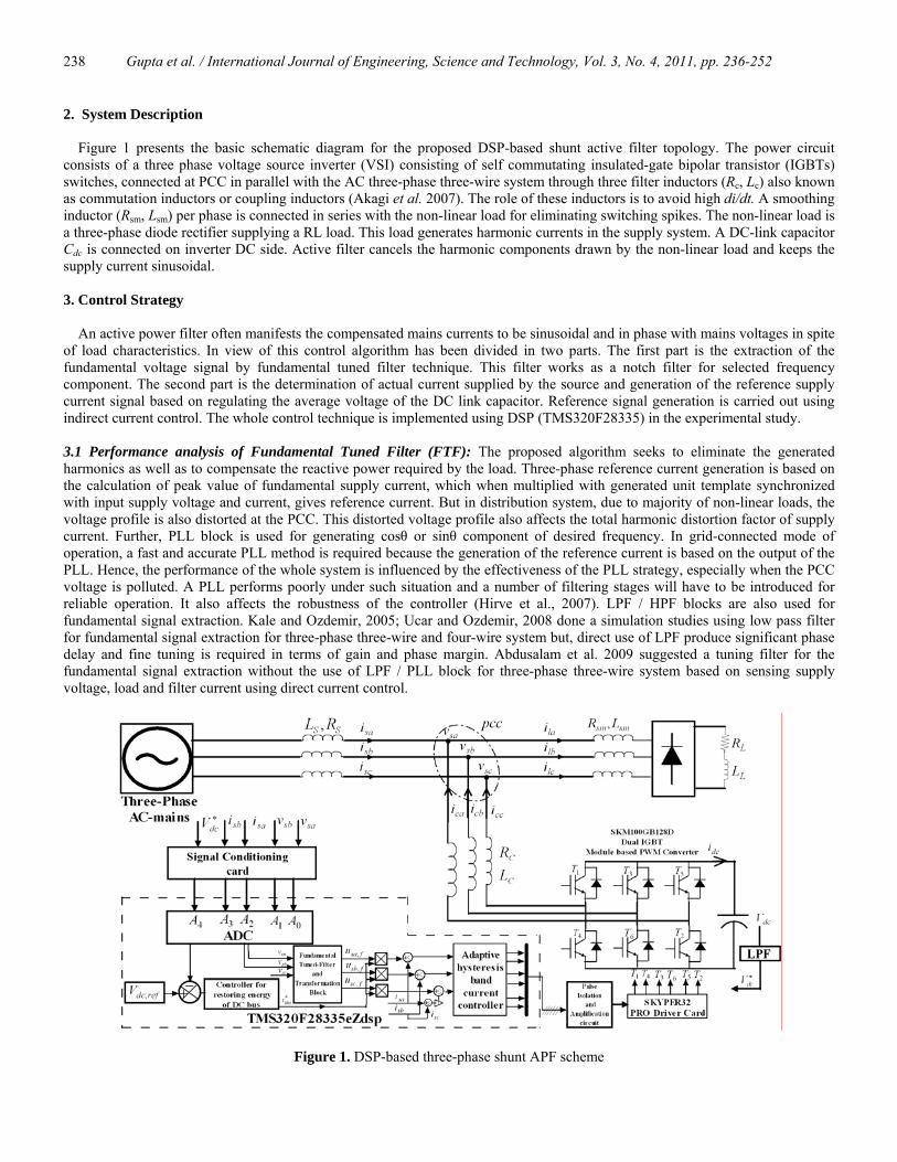
2. System Description Figure 1 presents the basic schematic diagram for the proposed DSP-based shunt active filter topology. The power circuit consists of a three phase voltage source inverter (VSI) consisting of self commutating insulated-gate bipolar transistor (IGBTs) switches, connected at PCC in parallel with the AC three-phase three-wire system through three filter inductors (Rc, Lc) also known as commutation inductors or coupling inductors (Akagi et al. 2007). The role of these inductors is to avoid high di/dt. A smoothing inductor (Rsm, Lsm) per phase is connected in series with the non-linear load for eliminating switching spikes. The non-linear load is a three-phase diode rectifier supplying a RL load. This load generates harmonic currents in the supply system. A DC-link capacitor Cdc is connected on inverter DC side. Active filter cancels the harmonic components drawn by the non-linear load and keeps the supply current sinusoidal. 3. Control Strategy An active power filter often manifests the compensated mains currents to be sinusoidal and in phase with mains voltages in spite of load characteristics. In view of this control algorithm has been divided in two parts. The first part is the extraction of the fundamental voltage signal by fundamental tuned filter technique. This filter works as a notch filter for selected frequency component. The second part is the determination of actual current supplied by the source and generation of the reference supply current signal based on regulating the average voltage of the DC link capacitor. Reference signal generation is carried out using indirect current control. The whole control technique is implemented using DSP (TMS320F28335) in the experimental study. 3.1 Performance analysis of Fundamental Tuned Filter (FTF): The proposed algorithm seeks to eliminate the generated harmonics as well as to compensate the reactive power required by the load. Three-phase reference current generation is based on the calculation of peak value of fundamental supply current, which when multiplied with generated unit template synchronized with input supply voltage and current, gives reference current. But in distribution system, due to majority of non-linear loads, the voltage profile is also distorted at the PCC. This distorted voltage profile also affects the total harmonic distortion factor of supply current. Further, PLL block is used for generating cosθ or sinθ component of desired frequency. In grid-connected mode of operation, a fast and accurate PLL method is required because the generation of the reference current is based on the output of the PLL. Hence, the performance of the whole system is influenced by the effectiveness of the PLL strategy, especially when the PCC voltage is polluted. A PLL performs poorly under such situation and a number of filtering stages will have to be introduced for reliable operation. It also affects the robustness of the controller (Hirve et al., 2007). LPF / HPF blocks are also used for fundamental signal extraction. Kale and Ozdemir, 2005; Ucar and Ozdemir, 2008 done a simulation studies using low pass filter for fundamental signal extraction for three-phase three-wire and four-wire system but, direct use of LPF produce significant phase delay and fine tuning is required in terms of gain and phase margin. Abdusalam et al. 2009 suggested a tuning filter for the fundamental signal extraction without the use of LPF / PLL block for three-phase three-wire system based on sensing supply voltage, load and filter current using direct current control.
Figure 1. DSP-based three-phase shunt APF scheme
Gupta et al. / International Journal of Engineering, Science and Technology, Vol. 3, No. 4, 2011, pp. 236-252
239
Singh et al. (2000, 2007) experimentally proved that comparison of reference filter current ( ∗∗∗fcfbfa iii ,, ) from actual filter current
( fcfbfa iii ,, ) based techniques also known as direct current control, produces switching ripples in compensated supply current during the transition of step-wave shaped load current. In comparison to direct current control, indirect current control offers notches free sinusoidal supply due to fast response and feed-back control in which switching pattern is generated by comparing actual and reference supply current signal. Also, control algorithm based on load and filter current sensing requires more number of sensors, hence more number of signals has to be processed by the processor in the process of reference signal generation. This reduces the dynamic response of the APF due to handling more number of signals and simultaneously increases the overall system cost (Chandra et al., 2000). In view of reducing switching ripples and number of sensors count, a DSP based modified tuned filter control strategy is used to generate the fundamental signal in electrical distribution system based on sensing distorted supply voltage and supply current without using load or filter current measurement. Reference current generation technique is based on comparing actual and calculated source current instead of filter current for overcoming the problem of switching ripples. The integration of an instantaneous signal Ixy in synchronous reference frame can be given by Sxy (Hong-Seok et al., 1999).
∫ ⋅⋅= − dttIeetS xyjwtjwt
xy )()( (1)
Applying Laplace transformation on Eqn. (1), the following transfer function can be obtained:
)()()()()( 22 ωω +⋅+== sjssIsSsT xyxy (2)
For limiting the T(s) magnitude, a constant X1 is used to obtain FTF at cut-off frequency ωc, hence the transfer function becomes:
))(()()()()( 22111 ccxyxy XsXjXssIsSsT ωω ++⋅⋅++== (3)
The optimized value of constant X1 is calculated by taking square root of α-β component of input voltage / current signal. This produces flexibility in selecting gain value even in steady-state and dynamic load condition. Input and output instantaneous signal Ixy and Sxy can be represented by ( bia ⋅+ ) and ( bia ˆˆ ⋅+ ), respectively. ( bia ⋅+ ) and ( bia ˆˆ ⋅+ ) signals can be voltage or current signal, respectively before and after filtering. Solving Eqn. (3) for above representation:
11122
1
11122
1
111111
221
221
1111
221
221
221
11
))(()()))(((ˆ)())(()))(((ˆ
))(()()())(()))(((ˆ)))(((ˆ
))(())(()))(((ˆ)))(((ˆ
))(()(
)()()(ˆ)(ˆ
XXssbXsaXssb
XsbXXssaXssa
XXssbiXsaiXsbXXssaXssbiXssa
XiXssbiXiXssaXssbiXssa
XsXiXs
sbisasbisa
cc
cc
cc
cc
cc
cc
c
c
⋅++⋅⋅=++
⋅⋅−⋅+=++
⋅+⋅+⋅⋅⋅+⋅⋅−⋅+=++⋅+++
⋅⋅++⋅+⋅⋅++=++⋅+++
++⋅⋅++
=⋅+⋅+
ωω
ωω
ωωωω
ωωωω
ωω
(4)
By separating real and imaginary part and rearranging them, the following expression can be obtained.
)()(
)()(
)()(ˆ22
1
122
1
11 sbXsXsa
XsXsXsa
c
c
c⋅
++⋅
−⋅++
+=
ωω
ω 5(a)
)()(
)()()(
)(ˆ 221
1122
1
1 sbXs
XsXsaXsXsb
cc
c ⋅++
++⋅
++⋅
=ωω
ω 5(b)
The value of a(s) and b(s) from Eqn. 5(a) can be written as:
c
c
c XXssb
XsXsXsbsa
ωω
ω ⋅++
⋅⎥⎥⎦
⎤
⎢⎢⎣
⎡
+++
−=1
221
221
11 )()()(
)()(ˆ)( 6(a)
)(
)()()(
)(ˆ)(11
221
221
1
XsXXssa
XsXsbsb c
c
c
+⋅++
⋅⎥⎥⎦
⎤
⎢⎢⎣
⎡
++−=
ωω
ω 6(b)
Gupta et al. / International Journal of Engineering, Science and Technology, Vol. 3, No. 4, 2011, pp. 236-252
240
Similarly, the value of a(s) and b(s) from Eqn. 5(b) can be written as:
)(
)()()(
)(ˆ)(11
221
221
1
XsXXssb
XsXsasa c
c
c
+⋅++
⋅⎥⎥⎦
⎤
⎢⎢⎣
⎡
+++=
ωω
ω 7(a)
c
c
c XXssa
XsXsXsasb
ωω
ω ⋅++
⋅⎥⎥⎦
⎤
⎢⎢⎣
⎡
+++
−−=1
221
221
11 )()()(
)()(ˆ)1()( 7(b)
Equating a(s) of Eqns. 6(a) and 7(a), equating b(s) of Eqns. 6(b) and 7(b), the following expression can be obtained:
[ ]
[ ] )(ˆ)(ˆ)()(ˆ
)(ˆ)(ˆ)()(ˆ
1
1
sas
sbsbs
Xsb
sbs
sasas
Xsa
c
c
⋅+−=
⋅−−=
ω
ω
(8)
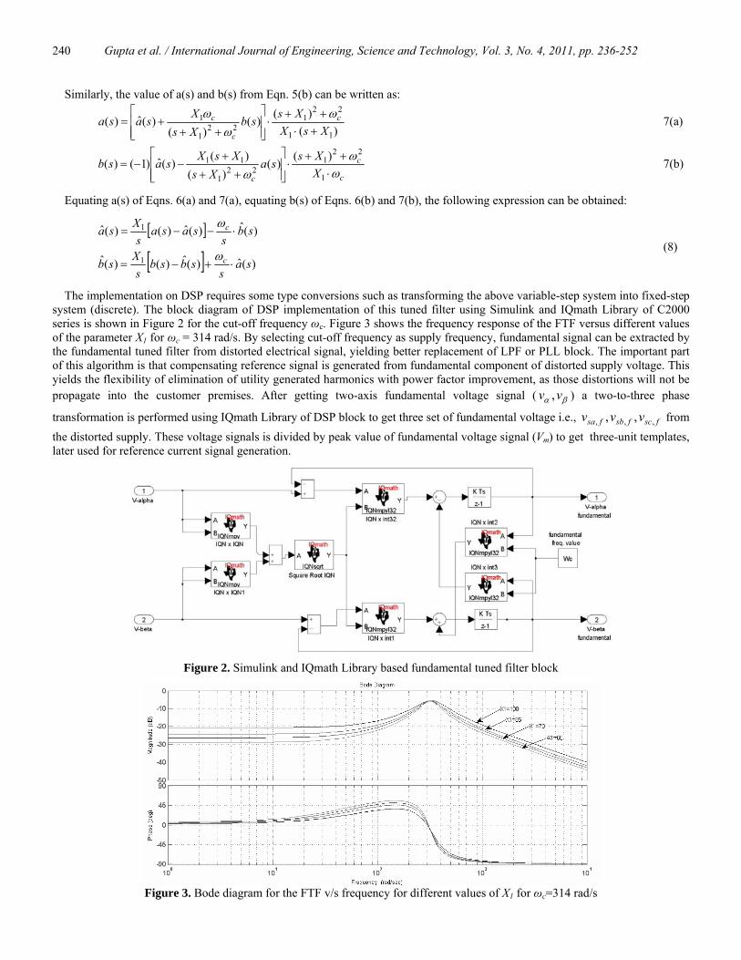
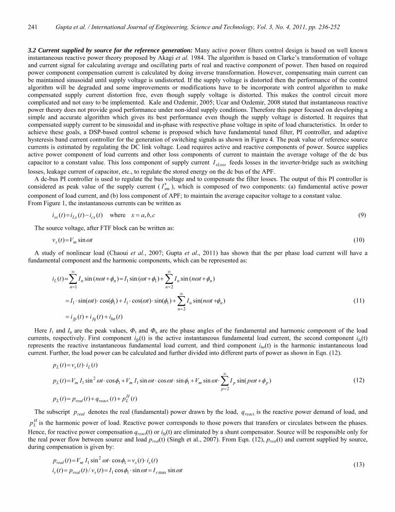
The implementation on DSP requires some type conversions such as transforming the above variable-step system into fixed-step system (discrete). The block diagram of DSP implementation of this tuned filter using Simulink and IQmath Library of C2000 series is shown in Figure 2 for the cut-off frequency ωc. Figure 3 shows the frequency response of the FTF versus different values of the parameter X1 for ωc = 314 rad/s. By selecting cut-off frequency as supply frequency, fundamental signal can be extracted by the fundamental tuned filter from distorted electrical signal, yielding better replacement of LPF or PLL block. The important part of this algorithm is that compensating reference signal is generated from fundamental component of distorted supply voltage. This yields the flexibility of elimination of utility generated harmonics with power factor improvement, as those distortions will not be propagate into the customer premises. After getting two-axis fundamental voltage signal ( βα vv , ) a two-to-three phase
transformation is performed using IQmath Library of DSP block to get three set of fundamental voltage i.e., fscfsbfsa vvv ,,, ,, from the distorted supply. These voltage signals is divided by peak value of fundamental voltage signal (Vm) to get three-unit templates, later used for reference current signal generation.
Figure 2. Simulink and IQmath Library based fundamental tuned filter block
Figure 3. Bode diagram for the FTF v/s frequency for different values of X1 for ωc=314 rad/s
Gupta et al. / International Journal of Engineering, Science and Technology, Vol. 3, No. 4, 2011, pp. 236-252
241
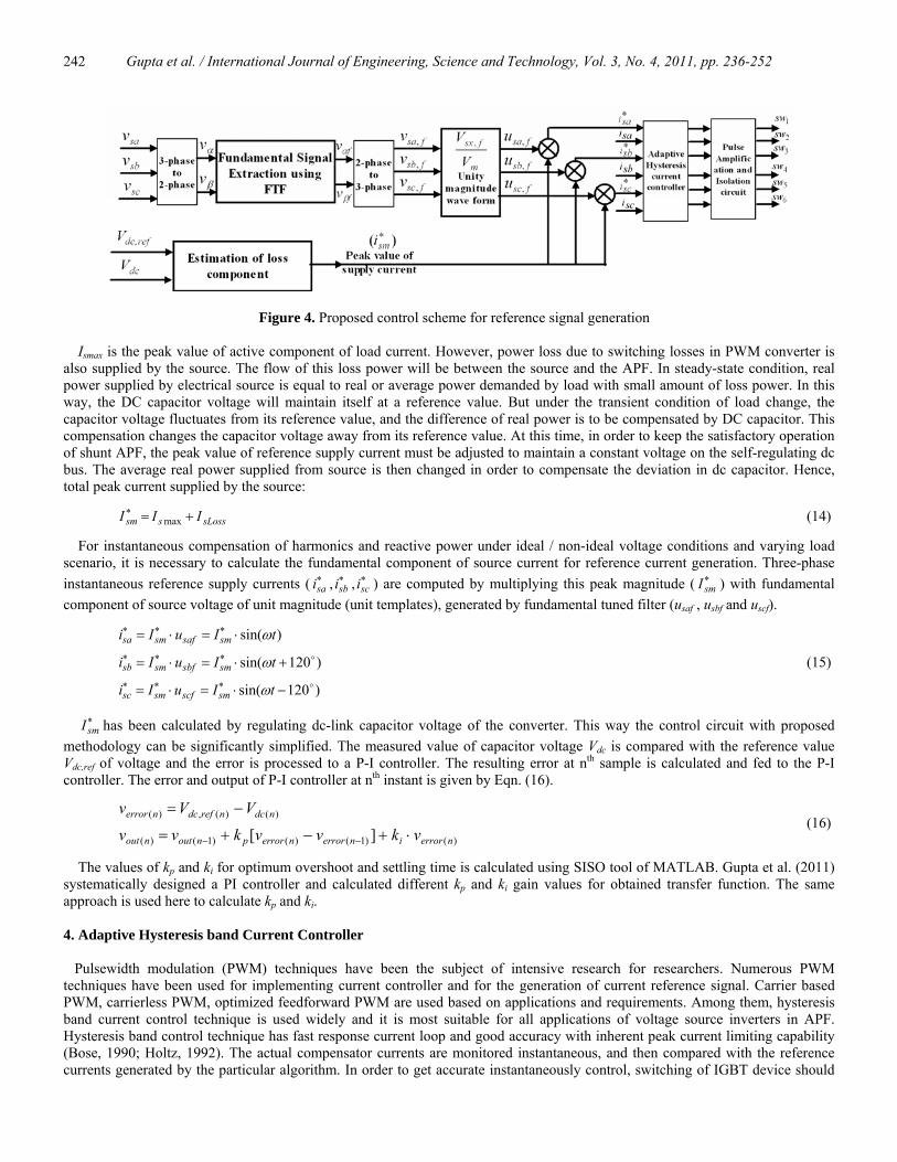
3.2 Current supplied by source for the reference generation: Many active power filters control design is based on well known instantaneous reactive power theory proposed by Akagi et al. 1984. The algorithm is based on Clarke’s transformation of voltage and current signal for calculating average and oscillating parts of real and reactive component of power. Then based on required power component compensation current is calculated by doing inverse transformation. However, compensating main current can be maintained sinusoidal until supply voltage is undistorted. If the supply voltage is distorted then the performance of the control algorithm will be degraded and some improvements or modifications have to be incorporate with control algorithm to make compensated supply current distortion free, even though supply voltage is distorted. This makes the control circuit more complicated and not easy to be implemented. Kale and Ozdemir, 2005; Ucar and Ozdemir, 2008 stated that instantaneous reactive power theory does not provide good performance under non-ideal supply conditions. Therefore this paper focused on developing a simple and accurate algorithm which gives its best performance even though the supply voltage is distorted. It requires that compensated supply current to be sinusoidal and in-phase with respective phase voltage in spite of load characteristics. In order to achieve these goals, a DSP-based control scheme is proposed which have fundamental tuned filter, PI controller, and adaptive hysteresis band current controller for the generation of switching signals as shown in Figure 4. The peak value of reference source currents is estimated by regulating the DC link voltage. Load requires active and reactive components of power. Source supplies active power component of load currents and other loss components of current to maintain the average voltage of the dc bus capacitor to a constant value. This loss component of supply current sLossI feeds losses in the inverter-bridge such as switching losses, leakage current of capacitor, etc., to regulate the stored energy on the dc bus of the APF. A dc-bus PI controller is used to regulate the bus voltage and to compensate the filter losses. The output of this PI controller is considered as peak value of the supply current ( ∗
smI ), which is composed of two components: (a) fundamental active power component of load current, and (b) loss component of APF; to maintain the average capacitor voltage to a constant value. From Figure 1, the instantaneous currents can be written as
cbaxtititi cxLxsx ,,where)()()( =−= (9)
The source voltage, after FTF block can be written as:
tVtv ms ωsin)( = (10)
A study of nonlinear load (Chaoui et al., 2007; Gupta et al., 2011) has shown that the per phase load current will have a fundamental component and the harmonic components, which can be represented as:
)()()(
)sin()sin()cos()cos()sin(
)(sin)(sin)(sin)(
21111
2111
tititi
tnItItI
tnItItnIti
hnfqfp
nn
n
nnn
nnnL
++=
++⋅⋅+⋅⋅=
+++=+=
∑
∑∑∞
=
∞
=
∞
=
φωφωφω
φωφωφω
(11)
Here I1 and In are the peak values, Φ1 and Φn are the phase angles of the fundamental and harmonic component of the load currents, respectively. First component ifp(t) is the active instantaneous fundamental load current, the second component ifq(t) represents the reactive instantaneous fundamental load current, and third component ihn(t) is the harmonic instantaneous load current. Further, the load power can be calculated and further divided into different parts of power as shown in Eqn. (12).
)()()()(
)sin(sinsincossincossin)(
)()()(
.
2111
21
tptqtptp
tpItVttIVtIVtp
titvtp
HLreactrealL
pppmmmL
LsL
++=
+⋅+⋅⋅+⋅=
⋅=
∑∞
=
φωωφωωφω (12)
The subscript realp denotes the real (fundamental) power drawn by the load, .reactq is the reactive power demand of load, and HLp is the harmonic power of load. Reactive power corresponds to those powers that transfers or circulates between the phases.
Hence, for reactive power compensation qreact(t) or ifq(t) are eliminated by a shunt compensator. Source will be responsible only for the real power flow between source and load preal(t) (Singh et al., 2007). From Eqn. (12), preal(t) and current supplied by source, during compensation is given by:
tItItvtpti
titvtIVtp
ssreals
ssmreal
ωωφφω
sinsincos)(/)()()()(cossin)(
max11
12
1
=⋅==⋅=⋅= (13)
Gupta et al. / International Journal of Engineering, Science and Technology, Vol. 3, No. 4, 2011, pp. 236-252
242
Figure 4. Proposed control scheme for reference signal generation Ismax is the peak value of active component of load current. However, power loss due to switching losses in PWM converter is also supplied by the source. The flow of this loss power will be between the source and the APF. In steady-state condition, real power supplied by electrical source is equal to real or average power demanded by load with small amount of loss power. In this way, the DC capacitor voltage will maintain itself at a reference value. But under the transient condition of load change, the capacitor voltage fluctuates from its reference value, and the difference of real power is to be compensated by DC capacitor. This compensation changes the capacitor voltage away from its reference value. At this time, in order to keep the satisfactory operation of shunt APF, the peak value of reference supply current must be adjusted to maintain a constant voltage on the self-regulating dc bus. The average real power supplied from source is then changed in order to compensate the deviation in dc capacitor. Hence, total peak current supplied by the source:
sLossssm III +=∗max (14)
For instantaneous compensation of harmonics and reactive power under ideal / non-ideal voltage conditions and varying load scenario, it is necessary to calculate the fundamental component of source current for reference current generation. Three-phase instantaneous reference supply currents ( ∗∗∗
scsbsa iii ,, ) are computed by multiplying this peak magnitude ( ∗smI ) with fundamental
component of source voltage of unit magnitude (unit templates), generated by fundamental tuned filter (usaf , usbf and uscf).
)120sin(
)120sin(
)sin(
o
o
−⋅=⋅=
+⋅=⋅=
⋅=⋅=
∗∗∗
∗∗∗
∗∗∗
tIuIi
tIuIi
tIuIi
smscfsmsc
smsbfsmsb
smsafsmsa
ω
ω
ω
(15)
∗smI has been calculated by regulating dc-link capacitor voltage of the converter. This way the control circuit with proposed
methodology can be significantly simplified. The measured value of capacitor voltage Vdc is compared with the reference value Vdc,ref of voltage and the error is processed to a P-I controller. The resulting error at nth sample is calculated and fed to the P-I controller. The error and output of P-I controller at nth instant is given by Eqn. (16).
)()1()()1()(
)()(,)(
][ nerrorinerrornerrorpnoutnout
ndcnrefdcnerror
vkvvkvv
VVv
⋅+−+=
−=
−−
(16)
The values of kp and ki for optimum overshoot and settling time is calculated using SISO tool of MATLAB. Gupta et al. (2011) systematically designed a PI controller and calculated different kp and ki gain values for obtained transfer function. The same approach is used here to calculate kp and ki. 4. Adaptive Hysteresis band Current Controller Pulsewidth modulation (PWM) techniques have been the subject of intensive research for researchers. Numerous PWM techniques have been used for implementing current controller and for the generation of current reference signal. Carrier based PWM, carrierless PWM, optimized feedforward PWM are used based on applications and requirements. Among them, hysteresis band current control technique is used widely and it is most suitable for all applications of voltage source inverters in APF. Hysteresis band control technique has fast response current loop and good accuracy with inherent peak current limiting capability (Bose, 1990; Holtz, 1992). The actual compensator currents are monitored instantaneous, and then compared with the reference currents generated by the particular algorithm. In order to get accurate instantaneously control, switching of IGBT device should
Gupta et al. / International Journal of Engineering, Science and Technology, Vol. 3, No. 4, 2011, pp. 236-252
243
be such that the error signal should approach nearly to zero, thus provides quick response. Generally, three hysteresis current controller with fixed band which derives the switching signals of three phase IGBT based VSI bridge is used. Each hysteresis controller determines the switching pattern of one leg of the inverter such that the error of the corresponding phase current is maintained within the defined band. The switching logic for ‘phase-a’ is formulated as follows: if )( bsasa hii −< ∗ , then the upper switch is OFF and the lower switch
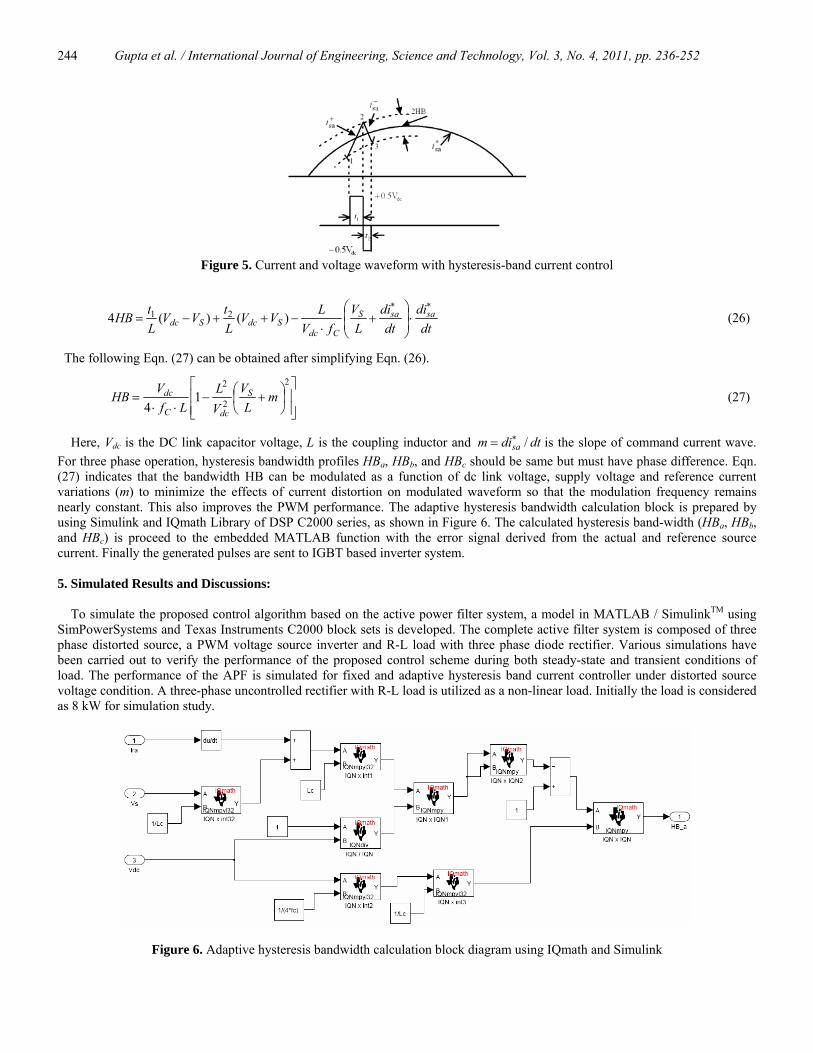
is ON in the phase “a” leg, then Sa =1 ; if )( bsasa hii +> ∗ , then the upper switch is ON and the lower switch is OFF in the phase “a” leg, then Sa=0. In same fashion, the switching of phase-b and c devices can be derived using hb as the width of hysteresis band. Current signal oscillates between upper and lower limits of the hysteresis band. The switching frequency of hysteresis band current control depends on this fast variation of current. The rate of change of actual reference current or the APF current varies the switching frequency. Hence, in this process of switching operation, the switching frequency does not remain constant due to fast rate of change. Switching frequency varies along with current waveform. Hence, the limitation of this fixed band hysteresis current controller is that its switching frequency is not constant and varies within a specified band because peak-to-peak current ripple is required to be controlled at all points of the fundamental frequency wave (Bose, 1990). The switching frequency of APF system also depends on the system parameters like, APF DC-link voltage, coupling inductors, etc. The bandwidth of the hysteresis band determines the current shaping error. Average switching frequency of active power filter can be controlled by changing the bandwidth of hysteresis band. Hence, adaptive hysteresis band current controller is used in comparison with fixed band hysteresis current controller in order to achieve nearly constant switching frequency. The adaptive hysteresis band controller proposed by Bose for machine drive system is adapted here for three-phase three-wire active power filter system based on indirect current control theory. Figure 5 shows the PWM current and voltage waves for phase a. When current crosses the lower hysteresis band at point 1, the upper switch of the inverter leg “a” will be turned-on. The inverter output voltage will rise and the current will also increase. Similarly, when the current touches the upper band limit then the inverter output voltage will start decaying, and hence, the current will start decaying by turn-on the lower switch of same leg. The following Eqns. can be written for the switching interval t1 and t2.
)(1Sdc
sa VVLdt
di−=
+
(17)
)(1Sdc
sa VVLdt
di+−=
−
(18)
Where L is the phase inductance, and dtdisa /+ and dtdisa /− are the respective rising and falling current segments. The following Eqns. can be written for switching intervals t1 to t2 from Figure 5.
HBtdt
ditdt
di sasa 211 =−∗+
(19)
HBtdt
ditdt
di sasa 222 −=−∗−
(20)
c
C fTtt 1
21 ==+ (21)
Where fc is the switching frequency. Adding (19) and (20) and substituting in (21):
01.21 =−+∗−+
C
sasasa
fdtdit
dtdit
dtdi (22)
Eqn. (23) can be obtained by substituting (17) and (18) in (22).
01)()( 21 =−+−−∗
dtdi
fVV
LtVV
Lt sa
CSdcSdc (23)
i.e. ⎟⎟⎠
⎞⎜⎜⎝
⎛+
⋅=−
∗
dtdi
LV
fVLtt saS
Cdc21 (24)
Now subtracting (20) from (19):
HBttdt
ditdt
ditdt
di sasasa 4)( 2121 =−−−∗−+
(25)
Substituting (17), (18) and (24) in (25),
Gupta et al. / International Journal of Engineering, Science and Technology, Vol. 3, No. 4, 2011, pp. 236-252
244
Figure 5. Current and voltage waveform with hysteresis-band current control
dt
didt
diL
VfV
LVVLtVV
LtHB sasaS
CdcSdcSdc
∗∗
⋅⎟⎟⎠
⎞⎜⎜⎝
⎛+
⋅−++−= )()(4 21 (26)
The following Eqn. (27) can be obtained after simplifying Eqn. (26).
⎥⎥⎦
⎤
⎢⎢⎣
⎡⎟⎠⎞
⎜⎝⎛ +−
⋅⋅=
2
2
21
4m
LV
VL
LfVHB S
dcC
dc (27)
Here, Vdc is the DC link capacitor voltage, L is the coupling inductor and dtdim sa /∗= is the slope of command current wave. For three phase operation, hysteresis bandwidth profiles HBa, HBb, and HBc should be same but must have phase difference. Eqn. (27) indicates that the bandwidth HB can be modulated as a function of dc link voltage, supply voltage and reference current variations (m) to minimize the effects of current distortion on modulated waveform so that the modulation frequency remains nearly constant. This also improves the PWM performance. The adaptive hysteresis bandwidth calculation block is prepared by using Simulink and IQmath Library of DSP C2000 series, as shown in Figure 6. The calculated hysteresis band-width (HBa, HBb, and HBc) is proceed to the embedded MATLAB function with the error signal derived from the actual and reference source current. Finally the generated pulses are sent to IGBT based inverter system. 5. Simulated Results and Discussions: To simulate the proposed control algorithm based on the active power filter system, a model in MATLAB / SimulinkTM using SimPowerSystems and Texas Instruments C2000 block sets is developed. The complete active filter system is composed of three phase distorted source, a PWM voltage source inverter and R-L load with three phase diode rectifier. Various simulations have been carried out to verify the performance of the proposed control scheme during both steady-state and transient conditions of load. The performance of the APF is simulated for fixed and adaptive hysteresis band current controller under distorted source voltage condition. A three-phase uncontrolled rectifier with R-L load is utilized as a non-linear load. Initially the load is considered as 8 kW for simulation study.
Figure 6. Adaptive hysteresis bandwidth calculation block diagram using IQmath and Simulink
Gupta et al. / International Journal of Engineering, Science and Technology, Vol. 3, No. 4, 2011, pp. 236-252
245
The APF is switched on at 0.05 sec in both the cases of hysteresis band. The APF parameters that are used for the simulation study are given in Appendix A. In simulation, the supply voltage is taken distorted with nearly 13% distortion of 5th and 6% distortion of 7th harmonic and total THD of the supply voltage is about 14%. The distorted three-phase mains voltage is expressed as:
)1207sin(15)2405sin(30)120sin(328
)2407sin(15)1205sin(30)240sin(328
)7sin(15)5sin(30)sin(328
ooo
ooo
−⋅+−⋅+−⋅=
−⋅+−⋅+−⋅=
⋅+⋅+⋅=
tttv
tttv
tttv
sc
sb
sa
ωωω
ωωω
ωωω (26)
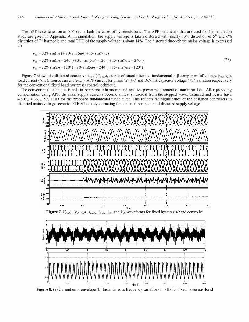
Figure 7 shows the distorted source voltage (VS-abc), output of tuned filter i.e. fundamental α-β component of voltage (vαf, vβf), load current (iL-abc), source current (iS-abc), APF current for phase ‘a’ (iCa) and DC-link capacitor voltage (Vdc) variation respectively for the conventional fixed band hysteresis control technique. The conventional technique is able to compensate harmonic and reactive power requirement of nonlinear load. After providing compensation using APF, the main supply currents become almost sinusoidal from the stepped wave, balanced and nearly have 4.80%, 4.36%, 5% THD for the proposed fundamental tuned filter. This reflects the significance of the designed controllers in distorted mains voltage scenario. FTF effectively extracting fundamental component of distorted supply voltage.
Figure 7. VS-abc, (vαf, vβf) , iL-abc, iS-abc, iCa, and Vdc waveforms for fixed hysteresis-band controller
Figure 8. (a) Current error envelope (b) Instantaneous frequency variations in kHz for fixed hysteresis-band
Gupta et al. / International Journal of Engineering, Science and Technology, Vol. 3, No. 4, 2011, pp. 236-252
246
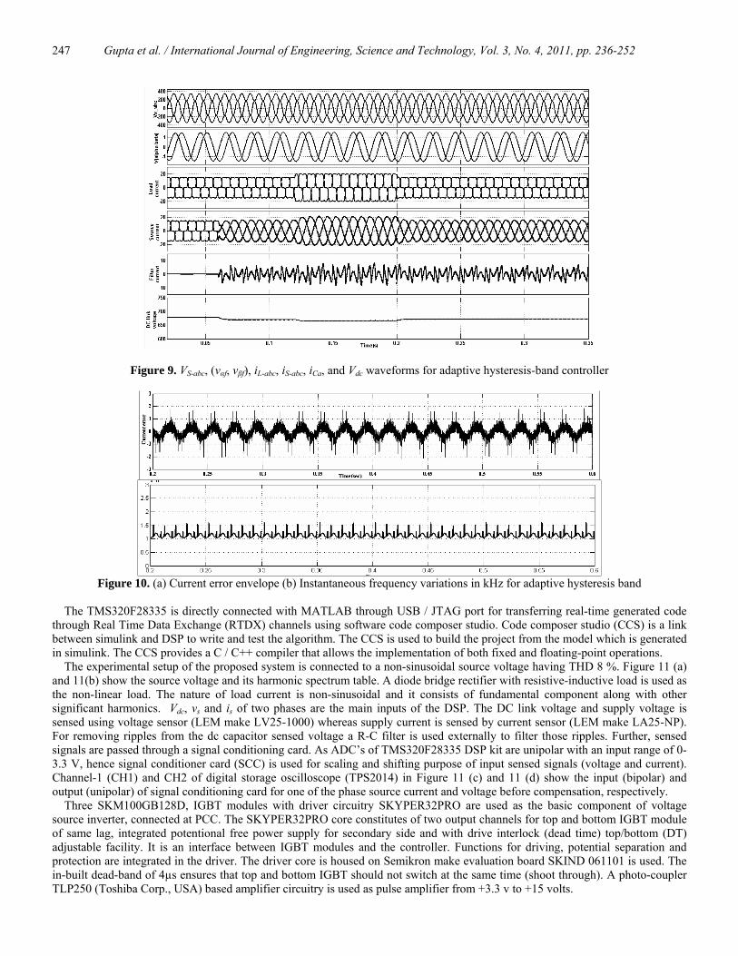
It can be seen that the performance of the APF is not affected by the supply distortion. Figure 8 (a) and 8(b) show the current error envelope due to the variation of reference (calculated) and actual source current, and the PWM APF switching frequency for conventional fixed band hysteresis control. Results depicted in Figure 8(b) shows that there is significant variation of switching frequency varied in the range of 8-14 kHz which directly effects the operation of IGBTs with their rating issue. However in practical applications, it is necessary to keep switching frequency constant to a certain limits, in order to determine switching device and its switching losses. Figure 9 shows VS-abc, (vαf, vβf), iL-abc, iS-abc, iCa and DC-link capacitor voltage variation, respectively for the proposed adaptive hysteresis band control technique. Results depicts that after providing the compensation source current is sinusoidal and having THD 2.49%, 1.94%, 2.61% , in all the three phases which is better than as obtained with conventional fixed band hysteresis current control as well as is within the limits of the harmonic standards of IEEE 519. The power factor is improved from 0.90 to 0.986 after providing the compensation by APF. To show the performance during the transient condition the load is changed at 0.16 s from 8 kW to 12 kW. Figure 9 shows the variation of DC-link capacitor voltage during the change in load. When the load current changes, capacitor voltage increases or decreases, to compensate the real or active demanded power supplied by the source. The DC-link voltage variation is controlled by using PI controller by regulating peak value of supply current. It is observed from Figure 9 that the response and performance of fundamental tuned filter including adaptive band control is found satisfactory under the steady-state and transient conditions. Figure 10(a) and 10(b) show the current error and APF switching frequency variations. It can be observed from Fig. 10(a) that current error ( ss iii −=Δ ∗ ) is much smaller as compared with fixed band hysteresis control shown in Figure 8(a). Reference source current and actual source current are close to each other which make the tracking error near to zero. In adaptive hysteresis band current control method, the switching frequency remains nearly constant with slight variation divergent to conventional fixed band hysteresis current control. A comparison has been carried out to show the effective extraction and compensation using fundamental tuned filter w.r.t low pass filter is shown in below table. 6. Implementation and Experimental Results
To validate the performance of the fundamental tuned filter and adaptive hysteresis band current control algorithm, a prototype model of shunt APF is developed and tested in the laboratory to verify the simulation results. The performance of control algorithm is investigated under steady-state and transient condition of load. The input step-down transformer (5KVA, 400/230 V) is connected to the supply. The three-phase active filter is achieved with a voltage source inverter which contains IGBT (SKM100GB128D) with specialized driver card circuit (SEMIKRON SKYPER32PRO) are used. The circuit diagram of hardware setup is shown in Figure 1. The DSP controller TMS320F28335 from Texas Instruments is used to implement the fundamental signal generation and adaptive hysteresis band control method. TMS320F28335 is a floating point digital signal processor with operating speed of 150 MIPS. The eZdspTM F28335 is a stand-alone card allowing designers to evaluate their application requirements. Further, the module is an excellent platform to develop and run software for the TMS320F28335 processor.
The choice of the DSP kit is suitable for control application, as it contains control peripherals like 16, 12-bit ADC channels, 56 general purpose digital input/output (GPIO) ports out of which 12 can also act as inbuilt ePWM channels; on board embedded USB JTAG controller; peripheral interrupt blocks. Though floating-point processor are costlier than fixed-point processor but more efforts are required to develop appropriate scaling factors to eliminate the effects of truncation or overflow in case of fixed-point processor. The control algorithm is developed using simulink and C2000 TI target support block sets.
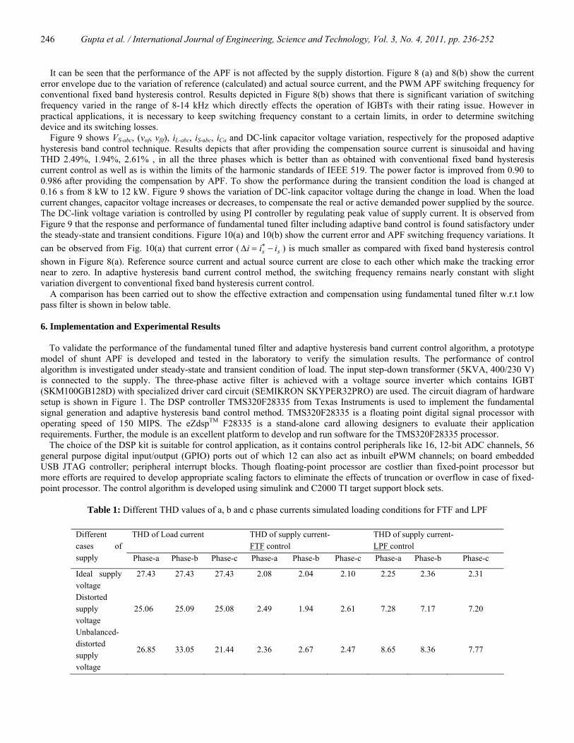
Table 1: Different THD values of a, b and c phase currents simulated loading conditions for FTF and LPF
THD of Load current THD of supply current-
FTF control THD of supply current- LPF control
Different cases of supply Phase-a Phase-b Phase-c Phase-a Phase-b Phase-c Phase-a Phase-b Phase-c
Ideal supply voltage
27.43 27.43 27.43 2.08 2.04 2.10 2.25 2.36 2.31
Distorted supply voltage
25.06 25.09 25.08 2.49 1.94 2.61 7.28 7.17 7.20
Unbalanced-distorted supply voltage
26.85 33.05 21.44 2.36 2.67 2.47 8.65 8.36 7.77
Gupta et al. / International Journal of Engineering, Science and Technology, Vol. 3, No. 4, 2011, pp. 236-252
247
Figure 9. VS-abc, (vαf, vβf), iL-abc, iS-abc, iCa, and Vdc waveforms for adaptive hysteresis-band controller
Figure 10. (a) Current error envelope (b) Instantaneous frequency variations in kHz for adaptive hysteresis band
The TMS320F28335 is directly connected with MATLAB through USB / JTAG port for transferring real-time generated code through Real Time Data Exchange (RTDX) channels using software code composer studio. Code composer studio (CCS) is a link between simulink and DSP to write and test the algorithm. The CCS is used to build the project from the model which is generated in simulink. The CCS provides a C / C++ compiler that allows the implementation of both fixed and floating-point operations. The experimental setup of the proposed system is connected to a non-sinusoidal source voltage having THD 8 %. Figure 11 (a) and 11(b) show the source voltage and its harmonic spectrum table. A diode bridge rectifier with resistive-inductive load is used as the non-linear load. The nature of load current is non-sinusoidal and it consists of fundamental component along with other significant harmonics. Vdc, vs and is of two phases are the main inputs of the DSP. The DC link voltage and supply voltage is sensed using voltage sensor (LEM make LV25-1000) whereas supply current is sensed by current sensor (LEM make LA25-NP). For removing ripples from the dc capacitor sensed voltage a R-C filter is used externally to filter those ripples. Further, sensed signals are passed through a signal conditioning card. As ADC’s of TMS320F28335 DSP kit are unipolar with an input range of 0-3.3 V, hence signal conditioner card (SCC) is used for scaling and shifting purpose of input sensed signals (voltage and current). Channel-1 (CH1) and CH2 of digital storage oscilloscope (TPS2014) in Figure 11 (c) and 11 (d) show the input (bipolar) and output (unipolar) of signal conditioning card for one of the phase source current and voltage before compensation, respectively. Three SKM100GB128D, IGBT modules with driver circuitry SKYPER32PRO are used as the basic component of voltage source inverter, connected at PCC. The SKYPER32PRO core constitutes of two output channels for top and bottom IGBT module of same lag, integrated potentional free power supply for secondary side and with drive interlock (dead time) top/bottom (DT) adjustable facility. It is an interface between IGBT modules and the controller. Functions for driving, potential separation and protection are integrated in the driver. The driver core is housed on Semikron make evaluation board SKIND 061101 is used. The in-built dead-band of 4µs ensures that top and bottom IGBT should not switch at the same time (shoot through). A photo-coupler TLP250 (Toshiba Corp., USA) based amplifier circuitry is used as pulse amplifier from +3.3 v to +15 volts.
Gupta et al. / International Journal of Engineering, Science and Technology, Vol. 3, No. 4, 2011, pp. 236-252
248
(a) (b)
(c) (d)
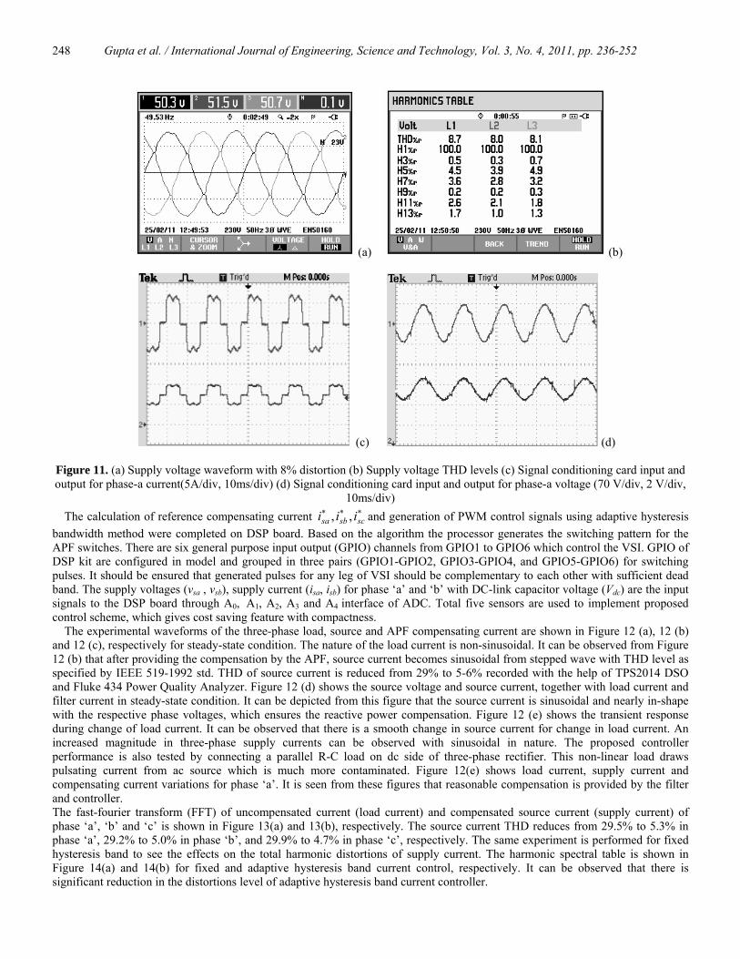
Figure 11. (a) Supply voltage waveform with 8% distortion (b) Supply voltage THD levels (c) Signal conditioning card input and output for phase-a current(5A/div, 10ms/div) (d) Signal conditioning card input and output for phase-a voltage (70 V/div, 2 V/div,
10ms/div) The calculation of reference compensating current ∗∗∗
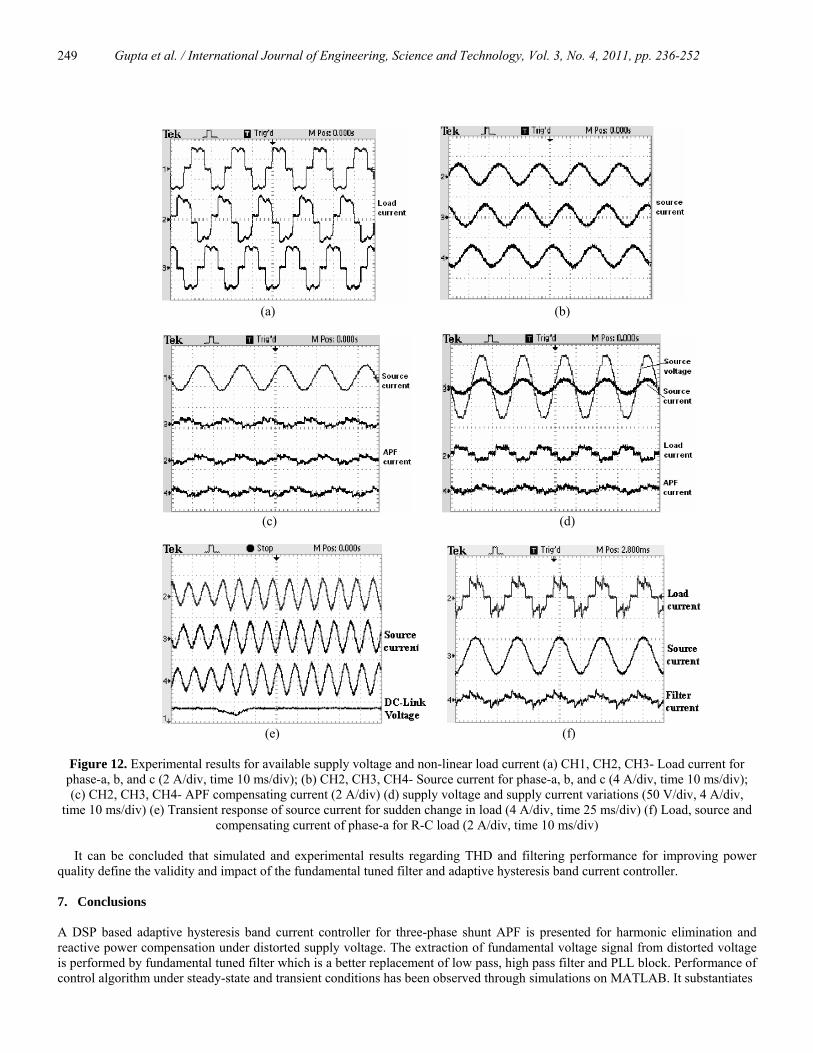
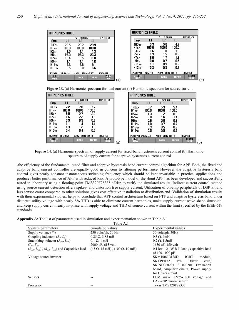
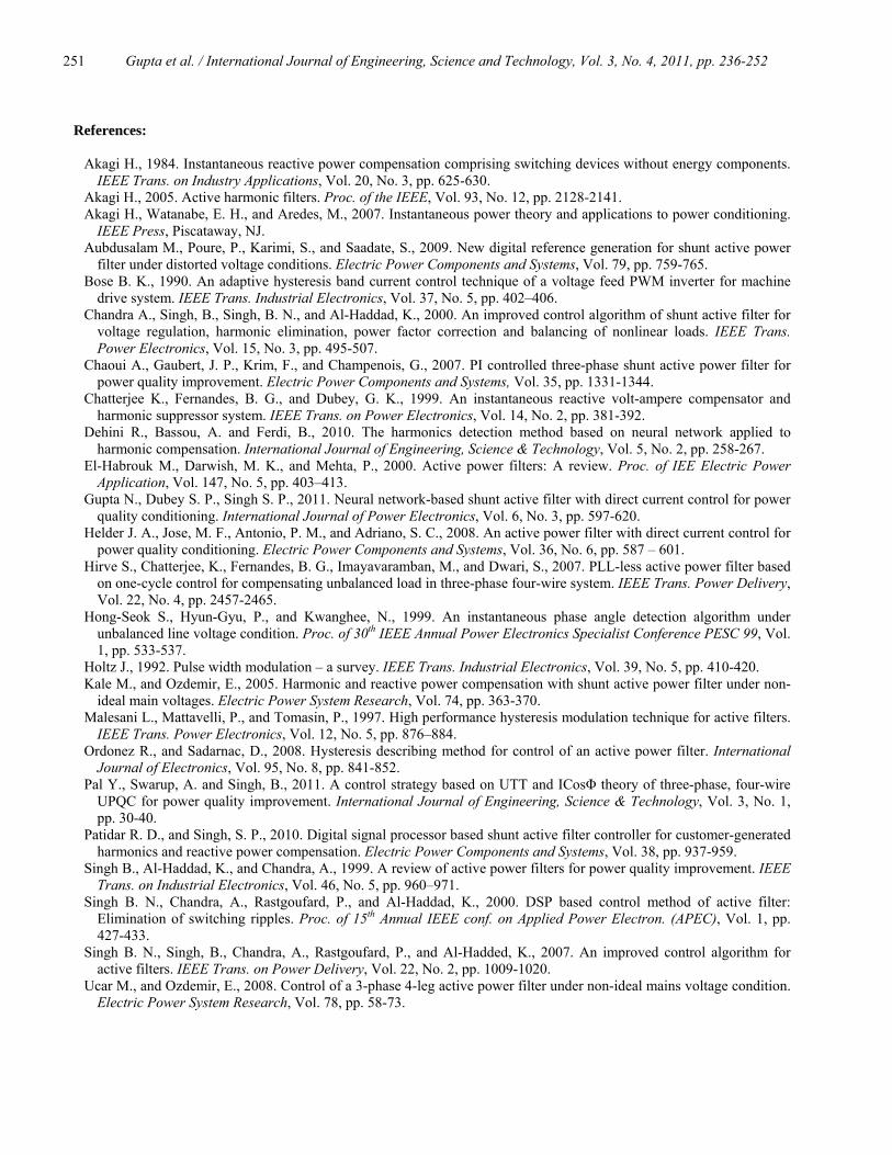
scsbsa iii ,, and generation of PWM control signals using adaptive hysteresis bandwidth method were completed on DSP board. Based on the algorithm the processor generates the switching pattern for the APF switches. There are six general purpose input output (GPIO) channels from GPIO1 to GPIO6 which control the VSI. GPIO of DSP kit are configured in model and grouped in three pairs (GPIO1-GPIO2, GPIO3-GPIO4, and GPIO5-GPIO6) for switching pulses. It should be ensured that generated pulses for any leg of VSI should be complementary to each other with sufficient dead band. The supply voltages (vsa , vsb), supply current (isa, isb) for phase ‘a’ and ‘b’ with DC-link capacitor voltage (Vdc) are the input signals to the DSP board through A0, A1, A2, A3 and A4 interface of ADC. Total five sensors are used to implement proposed control scheme, which gives cost saving feature with compactness. The experimental waveforms of the three-phase load, source and APF compensating current are shown in Figure 12 (a), 12 (b) and 12 (c), respectively for steady-state condition. The nature of the load current is non-sinusoidal. It can be observed from Figure 12 (b) that after providing the compensation by the APF, source current becomes sinusoidal from stepped wave with THD level as specified by IEEE 519-1992 std. THD of source current is reduced from 29% to 5-6% recorded with the help of TPS2014 DSO and Fluke 434 Power Quality Analyzer. Figure 12 (d) shows the source voltage and source current, together with load current and filter current in steady-state condition. It can be depicted from this figure that the source current is sinusoidal and nearly in-shape with the respective phase voltages, which ensures the reactive power compensation. Figure 12 (e) shows the transient response during change of load current. It can be observed that there is a smooth change in source current for change in load current. An increased magnitude in three-phase supply currents can be observed with sinusoidal in nature. The proposed controller performance is also tested by connecting a parallel R-C load on dc side of three-phase rectifier. This non-linear load draws pulsating current from ac source which is much more contaminated. Figure 12(e) shows load current, supply current and compensating current variations for phase ‘a’. It is seen from these figures that reasonable compensation is provided by the filter and controller. The fast-fourier transform (FFT) of uncompensated current (load current) and compensated source current (supply current) of phase ‘a’, ‘b’ and ‘c’ is shown in Figure 13(a) and 13(b), respectively. The source current THD reduces from 29.5% to 5.3% in phase ‘a’, 29.2% to 5.0% in phase ‘b’, and 29.9% to 4.7% in phase ‘c’, respectively. The same experiment is performed for fixed hysteresis band to see the effects on the total harmonic distortions of supply current. The harmonic spectral table is shown in Figure 14(a) and 14(b) for fixed and adaptive hysteresis band current control, respectively. It can be observed that there is significant reduction in the distortions level of adaptive hysteresis band current controller.
Gupta et al. / International Journal of Engineering, Science and Technology, Vol. 3, No. 4, 2011, pp. 236-252
249
(a) (b)
(c) (d)
(e) (f)
Figure 12. Experimental results for available supply voltage and non-linear load current (a) CH1, CH2, CH3- Load current for
phase-a, b, and c (2 A/div, time 10 ms/div); (b) CH2, CH3, CH4- Source current for phase-a, b, and c (4 A/div, time 10 ms/div); (c) CH2, CH3, CH4- APF compensating current (2 A/div) (d) supply voltage and supply current variations (50 V/div, 4 A/div,
time 10 ms/div) (e) Transient response of source current for sudden change in load (4 A/div, time 25 ms/div) (f) Load, source and compensating current of phase-a for R-C load (2 A/div, time 10 ms/div)
It can be concluded that simulated and experimental results regarding THD and filtering performance for improving power quality define the validity and impact of the fundamental tuned filter and adaptive hysteresis band current controller. 7. Conclusions A DSP based adaptive hysteresis band current controller for three-phase shunt APF is presented for harmonic elimination and reactive power compensation under distorted supply voltage. The extraction of fundamental voltage signal from distorted voltage is performed by fundamental tuned filter which is a better replacement of low pass, high pass filter and PLL block. Performance of control algorithm under steady-state and transient conditions has been observed through simulations on MATLAB. It substantiates
Gupta et al. / International Journal of Engineering, Science and Technology, Vol. 3, No. 4, 2011, pp. 236-252
250
(a) (b)
Figure 13. (a) Harmonic spectrum for load current (b) Harmonic spectrum for source current
(a) (b)
Figure 14. (a) Harmonic-spectrum of supply current for fixed-band hysteresis current control (b) Harmonic- spectrum of supply current for adaptive-hysteresis current control
-the efficiency of the fundamental tuned filter and adaptive hysteresis band current control algorithm for APF. Both, the fixed and adaptive band current controller are equally good in concern to filtering performance. However the adaptive hysteresis band control gives nearly constant instantaneous switching frequency which should be kept invariable in practical applications and produces better performance of APF with reduced loss. A prototype model of the shunt APF has been developed and successfully tested in laboratory using a floating-point TMS320F28335 eZdsp to verify the simulated results. Indirect current control method using source current detection offers spikes- and distortion free supply current. Utilization of on-chip peripherals of DSP kit and less sensor count compared to other solutions gives cost effective installation at distribution-end. Validation of simulation results with their experimental studies, helps to conclude that APF control architecture based on FTF and adaptive hysteresis band under distorted utility voltage with nearly 8% THD is able to eliminate current harmonics, make supply current wave shape sinusoidal and keep supply current nearly in-phase with supply voltage and THD of source current within the limit specified by the IEEE-519 standards. Appendix A: The list of parameters used in simulation and experimentation shown in Table A.1
Table A.1 System parameters Simulated values Experimental values Supply voltage (Vs) 230 volts/ph, 50 Hz 50 volts/ph, 50Hz Coupling inductors (Rc, Lc) 0.25 Ω, 3.85 mH 0.3 Ω, 4mH Smoothing inductor (Rsm, Lsm) 0.1 Ω, 1 mH 0.2 Ω, 1.5mH Cdc, Vdc 2000 uF, 615 volt 1650 uF, 150 volt (RL1, LL1) , (RL2, LL2) and Capacitive load (45 Ω, 15 mH) , (100 Ω, 10 mH) 0.1 kw – 2 kW R-L load , capacitive load
of 100-1000 μF Voltage source inverter -- SKM100GB128D IGBT module,
SKYPER32 Pro Driver card, SKIND060201 / 070201 Evaluation board, Amplifier circuit, Power supply for Driver circuit.
Sensors -- LEM make LV25-1000 voltage and LA25-NP current sensor
Processor -- Texas TMS320F28335
Gupta et al. / International Journal of Engineering, Science and Technology, Vol. 3, No. 4, 2011, pp. 236-252
251
References:
Akagi H., 1984. Instantaneous reactive power compensation comprising switching devices without energy components. IEEE Trans. on Industry Applications, Vol. 20, No. 3, pp. 625-630.
Akagi H., 2005. Active harmonic filters. Proc. of the IEEE, Vol. 93, No. 12, pp. 2128-2141. Akagi H., Watanabe, E. H., and Aredes, M., 2007. Instantaneous power theory and applications to power conditioning.
IEEE Press, Piscataway, NJ. Aubdusalam M., Poure, P., Karimi, S., and Saadate, S., 2009. New digital reference generation for shunt active power
filter under distorted voltage conditions. Electric Power Components and Systems, Vol. 79, pp. 759-765. Bose B. K., 1990. An adaptive hysteresis band current control technique of a voltage feed PWM inverter for machine
drive system. IEEE Trans. Industrial Electronics, Vol. 37, No. 5, pp. 402–406. Chandra A., Singh, B., Singh, B. N., and Al-Haddad, K., 2000. An improved control algorithm of shunt active filter for
voltage regulation, harmonic elimination, power factor correction and balancing of nonlinear loads. IEEE Trans. Power Electronics, Vol. 15, No. 3, pp. 495-507.
Chaoui A., Gaubert, J. P., Krim, F., and Champenois, G., 2007. PI controlled three-phase shunt active power filter for power quality improvement. Electric Power Components and Systems, Vol. 35, pp. 1331-1344.
Chatterjee K., Fernandes, B. G., and Dubey, G. K., 1999. An instantaneous reactive volt-ampere compensator and harmonic suppressor system. IEEE Trans. on Power Electronics, Vol. 14, No. 2, pp. 381-392.
Dehini R., Bassou, A. and Ferdi, B., 2010. The harmonics detection method based on neural network applied to harmonic compensation. International Journal of Engineering, Science & Technology, Vol. 5, No. 2, pp. 258-267.
El-Habrouk M., Darwish, M. K., and Mehta, P., 2000. Active power filters: A review. Proc. of IEE Electric Power Application, Vol. 147, No. 5, pp. 403–413.
Gupta N., Dubey S. P., Singh S. P., 2011. Neural network-based shunt active filter with direct current control for power quality conditioning. International Journal of Power Electronics, Vol. 6, No. 3, pp. 597-620.
Helder J. A., Jose, M. F., Antonio, P. M., and Adriano, S. C., 2008. An active power filter with direct current control for power quality conditioning. Electric Power Components and Systems, Vol. 36, No. 6, pp. 587 – 601.
Hirve S., Chatterjee, K., Fernandes, B. G., Imayavaramban, M., and Dwari, S., 2007. PLL-less active power filter based on one-cycle control for compensating unbalanced load in three-phase four-wire system. IEEE Trans. Power Delivery, Vol. 22, No. 4, pp. 2457-2465.
Hong-Seok S., Hyun-Gyu, P., and Kwanghee, N., 1999. An instantaneous phase angle detection algorithm under unbalanced line voltage condition. Proc. of 30th IEEE Annual Power Electronics Specialist Conference PESC 99, Vol. 1, pp. 533-537.
Holtz J., 1992. Pulse width modulation – a survey. IEEE Trans. Industrial Electronics, Vol. 39, No. 5, pp. 410-420. Kale M., and Ozdemir, E., 2005. Harmonic and reactive power compensation with shunt active power filter under non-
ideal main voltages. Electric Power System Research, Vol. 74, pp. 363-370. Malesani L., Mattavelli, P., and Tomasin, P., 1997. High performance hysteresis modulation technique for active filters.
IEEE Trans. Power Electronics, Vol. 12, No. 5, pp. 876–884. Ordonez R., and Sadarnac, D., 2008. Hysteresis describing method for control of an active power filter. International
Journal of Electronics, Vol. 95, No. 8, pp. 841-852. Pal Y., Swarup, A. and Singh, B., 2011. A control strategy based on UTT and ICosΦ theory of three-phase, four-wire
UPQC for power quality improvement. International Journal of Engineering, Science & Technology, Vol. 3, No. 1, pp. 30-40.
Patidar R. D., and Singh, S. P., 2010. Digital signal processor based shunt active filter controller for customer-generated harmonics and reactive power compensation. Electric Power Components and Systems, Vol. 38, pp. 937-959.
Singh B., Al-Haddad, K., and Chandra, A., 1999. A review of active power filters for power quality improvement. IEEE Trans. on Industrial Electronics, Vol. 46, No. 5, pp. 960–971.
Singh B. N., Chandra, A., Rastgoufard, P., and Al-Haddad, K., 2000. DSP based control method of active filter: Elimination of switching ripples. Proc. of 15th Annual IEEE conf. on Applied Power Electron. (APEC), Vol. 1, pp. 427-433.
Singh B. N., Singh, B., Chandra, A., Rastgoufard, P., and Al-Hadded, K., 2007. An improved control algorithm for active filters. IEEE Trans. on Power Delivery, Vol. 22, No. 2, pp. 1009-1020.
Ucar M., and Ozdemir, E., 2008. Control of a 3-phase 4-leg active power filter under non-ideal mains voltage condition. Electric Power System Research, Vol. 78, pp. 58-73.

Gupta et al. / International Journal of Engineering, Science and Technology, Vol. 3, No. 4, 2011, pp. 236-252
252
Biographical notes Nitin Gupta graduated in Electrical Engineering from Government Engineering College, Kota, India in 2000. He completed his Master of Engineering in Power Electronics from M.P.U.A.T, Udaipur, India in 2007. He has also around seven years of teaching experience. Currently, he is pursuing research in the field of Power Quality at the Electrical Engineering Department of Indian Institute of Technology Roorkee, India. His fields of interest include active filters, reactive power and harmonics compensation, power factor correction, and robust controllers.
S.P. Singh received his B.Sc in Electrical Engineering from Aligarh Muslim University, Aligarh, India in 1978. He received his M.E. and his Ph.D. in Electrical Engineering from University of Roorkee, now Indian Institute of Technology Roorkee, India in 1980 and 1993, respectively. He has around 20 years of teaching experience and guided many renewable energy projects. Currently, he is a Professor in the Department of Electrical Engineering, Indian Institute of Technology, Roorkee, India. He has published more than fifty papers in referred international journals with many research articles in national and international conferences. He organised many workshops and short-term courses. He has been associated with many hydro power projects sponsored by Government of India. His field of interest includes electrical machines, power apparatus and electric drives, power quality, renewable energy sources, artificial intelligence and application of DSP for the control of power converters.
S.P. Dubey received his Bachelors in Electrical Engineering from Govt. Engineering College, now National Institute of Technology Raipur, India in 1995. He completed his Masters in Engineering (Power Apparatus and Electrical Drives) from Indian Institute of Technology Roorkee, Roorkee, India in 2000. He obtained Ph.D. degree from Birla Institute of Technology and Science, Pilani, India in 2006. He worked as Lecturer for six years and as Assistant Professor for one year in the Electrical and Electronics Engineering Group at Birla Institute of Technology and Science (B.I.T.S.), Pilani, and as an Assistant professor in the Department of Electrical Engineering, Indian Institute of Technology Roorkee, India. Currently, he is Professor in the Department of Electrical Engineering, R.C.E.T., Bhilai, INDIA. His current research interests include power converters, active filtering, power conditioning, AC and DC Drives, neural network and fuzzy logic based controller design for Electrical Drives, Genetic Algorithm Optimization technique for LC Filter Design.
Received April 2011 Accepted June 2011 Final acceptance in revised form July 2011


![ADAPTIVE HYSTERESIS CURRENT CONTROL OF INVERTER · PDF fileADAPTIVE HYSTERESIS CURRENT CONTROL OF INVERTER FOR SOLAR ... (ACMC), Sliding Mode Control (SMC) [13] ... all points of the](https://static.fdocuments.in/doc/165x107/5a87d0157f8b9a9f1b8e0a96/adaptive-hysteresis-current-control-of-inverter-hysteresis-current-control-of.jpg)


